Article

Effects of the Balance Hole Diameter on the Flow Characteristics of the Rear Chamber and the Disk Friction Loss in the Centrifugal Pump

1
Institute of Water Resources and Hydropower Research, Northwest A&F University, Yangling 712100, China
2
Key Laboratory of Agricultural Soil and Water Engineering in Arid and Semiarid Areas, Ministry of Educa-tion, Northwest A&F University, Yangling 712100, China
3
State Key Laboratory of Hydropower Equipment, Harbin Institute of Large Electrical Machinery, Harbin 150040, China
*
Authors to whom correspondence should be addressed.
Processes 2022, 10(3), 613; https://doi.org/10.3390/pr10030613
Submission received: 4 February 2022 / Revised: 3 March 2022 / Accepted: 17 March 2022 / Published: 21 March 2022
(This article belongs to the Special Issue Design and Optimization Method of Pumps)

Abstract

:
This paper studies the flow characteristics and disk friction loss of the rear chamber in a centrifugal pump at a design flow condition with six values of the balance holes at diameters from 0 to 12 mm. The results show that the turbulent boundary layer in the rear chamber is greatly affected by the leakage flow. When the balance hole diameter increases, the flow characteristics of the rear chamber is mainly restricted by the mainstream flow field of the volute. However, when the balance hole diameter is larger than the design value, the disk friction loss of the rear chamber remains basically unchanged. On the contrary, when the balance hole diameter is smaller than the design value, the larger the balance hole diameter the smaller the friction loss of the disk in the rear chamber area. The results of this paper provide a reference for reducing axial force and stable operation of a centrifugal pump.

1. Introduction

Axial force is one of the most important factors affecting the service life and stable operation of centrifugal pumps [1,2,3]. There is still uncertainty concerning the precise flow mechanisms of centrifugal pumps; it is hard to calculate and balance the axial force of centrifugal pumps accurately, which has become an important subject in the research of pump industry [4,5,6]. For the method of balancing the axial force of the balancing hole opening on the back cover of centrifugal pump impeller, the diameter of the balance hole is closely related to the magnitude of the axial force [7]. Wu et al. determined that liquid rotation angular velocity in a centrifugal pump chamber is half of the impeller rotation’s angular velocity [8]. Based on the theoretical analysis of the characteristics of liquid rotating flow in pump chamber, Chao et al. and Zhang et al. present a rotating liquid flow model in a pump chamber [9,10]. The results of their research show that the larger the clearance leakage, the smaller the ratio of liquid rotation angular velocity to impeller rotation angular velocity, and vice versa. Under the conditions of different Reynolds number, flow rate, and axial space ratio of the pump chamber, the velocity and pressure of liquid flow in the chamber of a centrifugal pump were measured with Doppler anemometer and pressure sensor, and a lot of experimental data were obtained [11]. By numerical calculation with or without the balance hole, and taking three different working conditions, it was found that the balance hole has a huge effect on the flow of liquid in the rear chamber along the tangential direction [12]. By the CFD numerical simulation of a multistage centrifugal pump, Salvadori et al. points out that the flow characteristics of liquid in the pump chamber must be analyzed in detail to calculate the axial force of the centrifugal pump accurately [13]. Lefor et al. considers that there is a turbulent boundary layer near the outer wall of the impeller’s back cover plate and the fixed inner wall [14]. The flow core region is between the two boundary layers, and the velocity of the flow core region varies slightly along the axial direction.
The disk friction loss represents the main energy loss in the centrifugal pump [15,16]. At present, the flow of liquid in the front chamber of the centrifugal pump impeller has already been studied in depth [17,18,19,20]. Due to the balance hole and seal ring, the flow of the rear chamber of the centrifugal pump impeller is more complex than that of the front chamber, which has great influence on the disk friction loss, clearance leakage, and axial force of the centrifugal pump impeller.
Motivated by the above discussions, this paper has three advantages which make the approach attractive compared with prior works. First, the full flow field is calculated by changing the diameter of the balance hole of the centrifugal pump impeller. Specifically, in the design of the flow operating point, this paper analyzes in detail the influence of the balance hole diameter based on the axial distribution law of the tangential and radial velocity of the liquid in the rear chamber at different angles (0°, 90°, 180°, and 270°) and different radii (0.6 R, 0.7 R, 0.8 R, and 0.9 R), when the balance hole diameter is 0 mm, 4 mm, 6 mm, 8 mm, 10 mm, and 12 mm, respectively. Second, the disk friction loss of the rear chamber is calculated by using the mean value of tangential velocity of liquid in the core region. Finally, the effects of the diameter of the balance hole on the liquid velocity in the rear chamber are revealed, and the causes of the disk friction loss can be obtained from the mechanism.

2. Research Object and Numerical Method

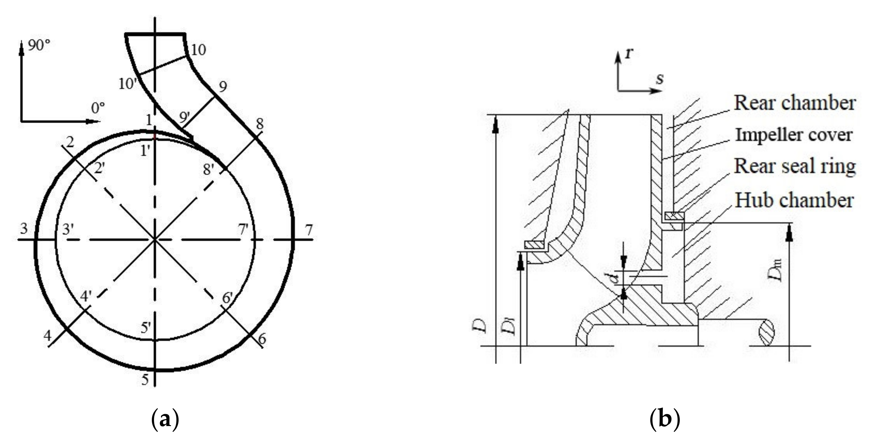
2.1. Research Object

In this paper, a single-stage single-suction centrifugal pump is studied. The impeller of the centrifugal pump is a closed impeller with double seal rings and balance holes. The main design parameters are shown in Table 1.
The three-dimensional solid models of centrifugal pump are built by Pro/E software shown in Figure 1.
The numerical calculation of the centrifugal pump is defined in the three-dimensional coordinate system. The impeller is fixed in the pump body and the axial width of the pump chamber remains unchanged. When the model is built, the impeller inlet is axially positive and rotates clockwise. The volute is seen from the back of the pump in Figure 2a. The rotation of the rotor is clockwise when looked at towards its front side. The calculation model diagram is shown in Figure 2.

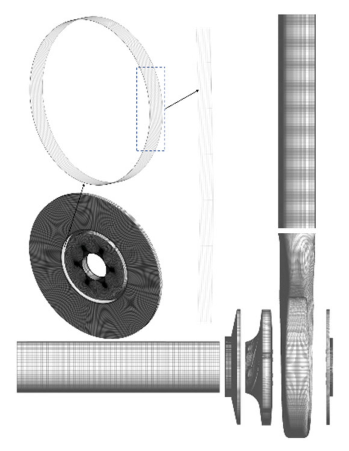
2.2. Numerical Calculation Method

In this paper, FLUENT software is used to carry out numerical calculations. The simulation methodology of the interaction of the flow is the “multiple reference model” (MRef) in the rotor and the flow in the stator. Boundary conditions are set as follows: the inlet boundary is set to the speed inlet without the swirling flow, and the outlet boundary is set to the free outflow form. The solid surface of the blade surface and the volute is set to no slip, and the turbulent flow near the wall is calculated by the standard wall function method [21]. The wall surface of the pump casing is set to be stationary, and the wall surface of the rear plate of the impeller is a rotating wall surface. The flow in the pump is set to an incompressible steady turbulent flow, and RNG k-ε is chosen as the turbulence model for the research [22]. RNG k-ε considers the rotation and swirling flow in the average flow, and can better deal with the flow with high strain rate and large degree of streamline bending. The time-averaged continuous equation and the Navier-Stokes equation in the relative coordinate system are used as the governing equations. The coupling calculation of pressure and velocity are calculated by the SIMPLEC algorithm.

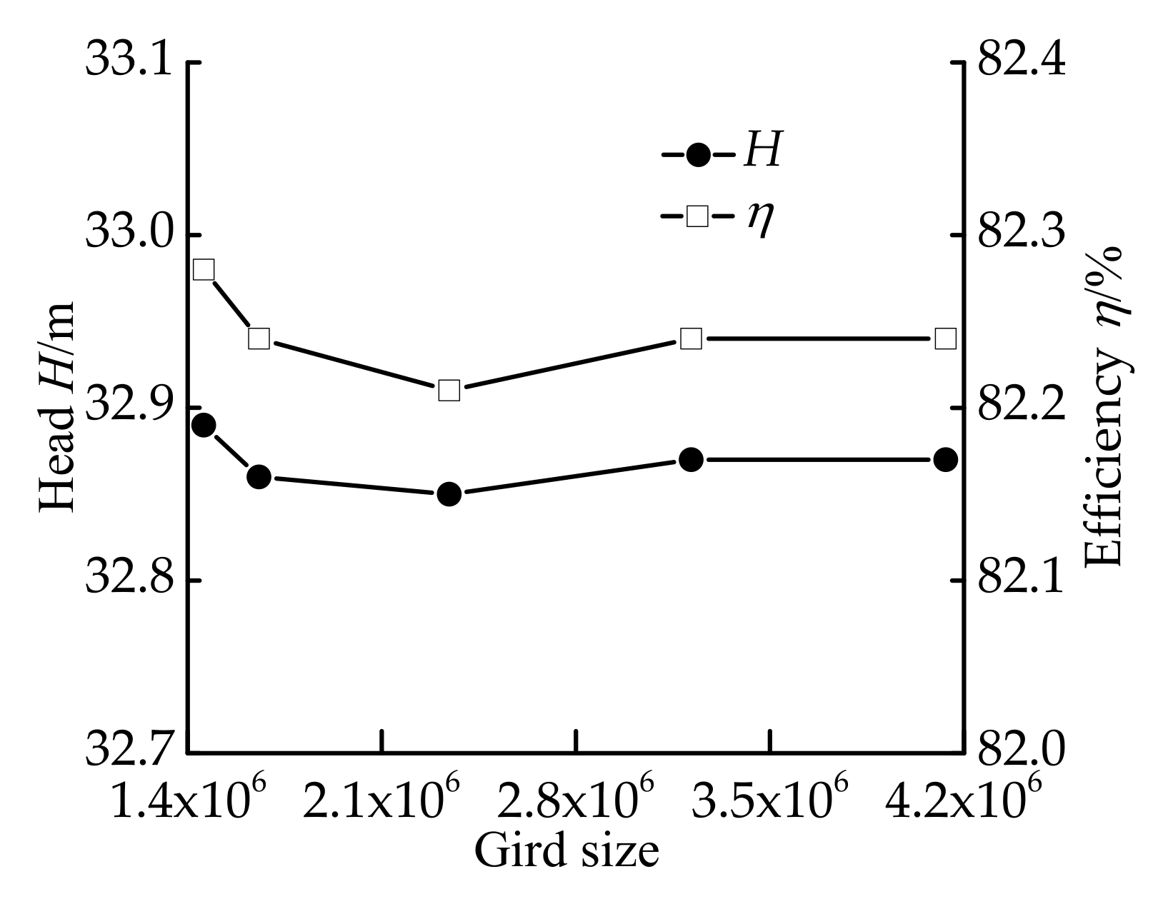
2.3. Computational Model Check

The hybrid grid has the advantages of flexible splitting and easy grid adaptive, and it is suitable for dealing with complex boundary problems [23]. The side chamber of the impeller rear cover is processed by a structural grid. The grid of the impeller is shown in Figure 3.
Generally, the grid independence of the calculation model is verified to improve the accuracy of the results in the numerical calculation [24]. Therefore, in order to eliminate the influence of the total number of grids over the liquid flow in the pump chamber of the centrifugal pump, this paper adopts the method of increasing the total number of centrifugal pump grids to verify the grid independence. As the efficiency η of the pump is jointly determined by its head, flow rate, and shaft power, Figure 4 shows the variation of efficiency and head of the centrifugal pump with the total number of grids from 1.46 million to 4.13 million at the design flow 1.0Qd working point, so as to exclude the influence of the grid number on the calculation results and reflect the grid independence verification results.
Figure 4 shows the efficiency change diagram with the total number of centrifugal pump grids from 1.46 million to 4.13 million. As shown in Figure 4, the change of the efficiency and head are always small during the increase of the total number of centrifugal pump grids. When the total number of centrifugal pump grids increased by 3.22 million to be as large as 4.13 million, the efficiency and head remained the same, and a grid-independent solution was obtained. In light of this, this paper uses 3.22 million as the overall grid number of centrifugal pumps.

3. Calculation Results and Analysis

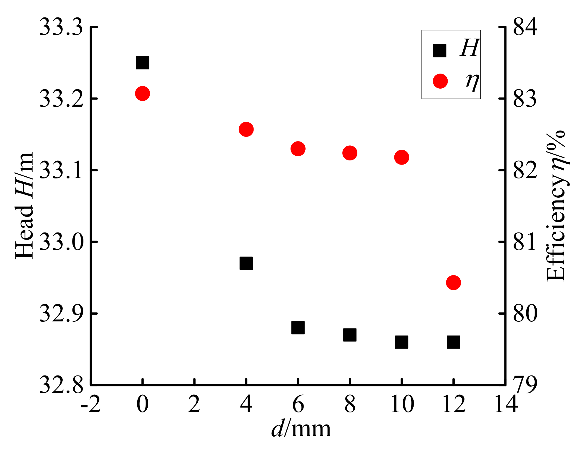
3.1. External Characteristics of Centrifugal Pump

The numerical calculation results for the external characteristic parameters of different balance hole diameter models at the design flow working point are shown in Figure 5.
In Figure 5, the numerical results of efficiency and head are showing a downward trend when the balance hole diameter is increased from 0 to 12 mm. When d = 0 mm, the centrifugal pump impeller has no balance hole, and the numerical calculation results of the head and efficiency are the largest compared with other numerical calculation results. When d = 12 mm, the head and efficiency are relatively small. When d = 8 mm, the numerical calculation results of the head are higher than the original design parameters of the pump and the relative error is 2.72%; the numerical calculation result of the efficiency is lower than the original design parameters of the pump, and the relative error is 1.53%.

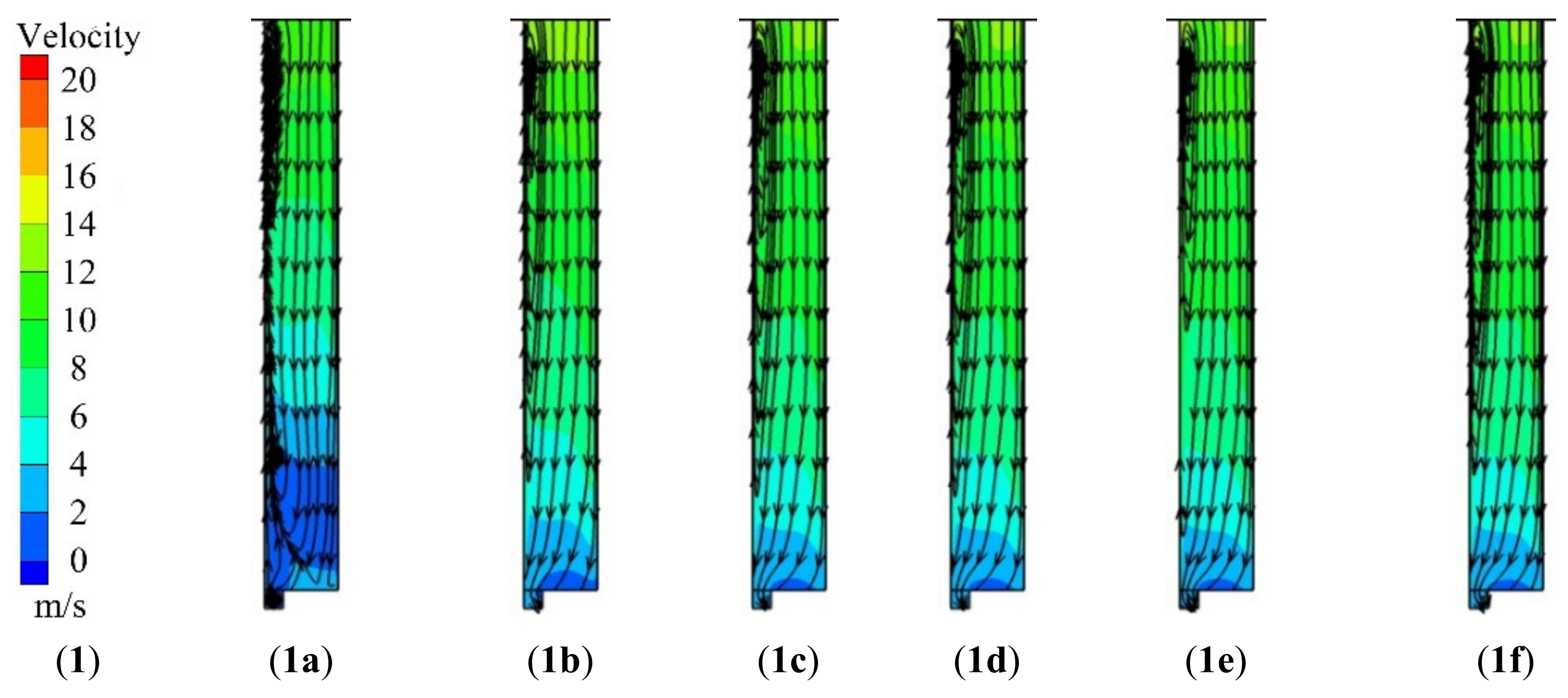
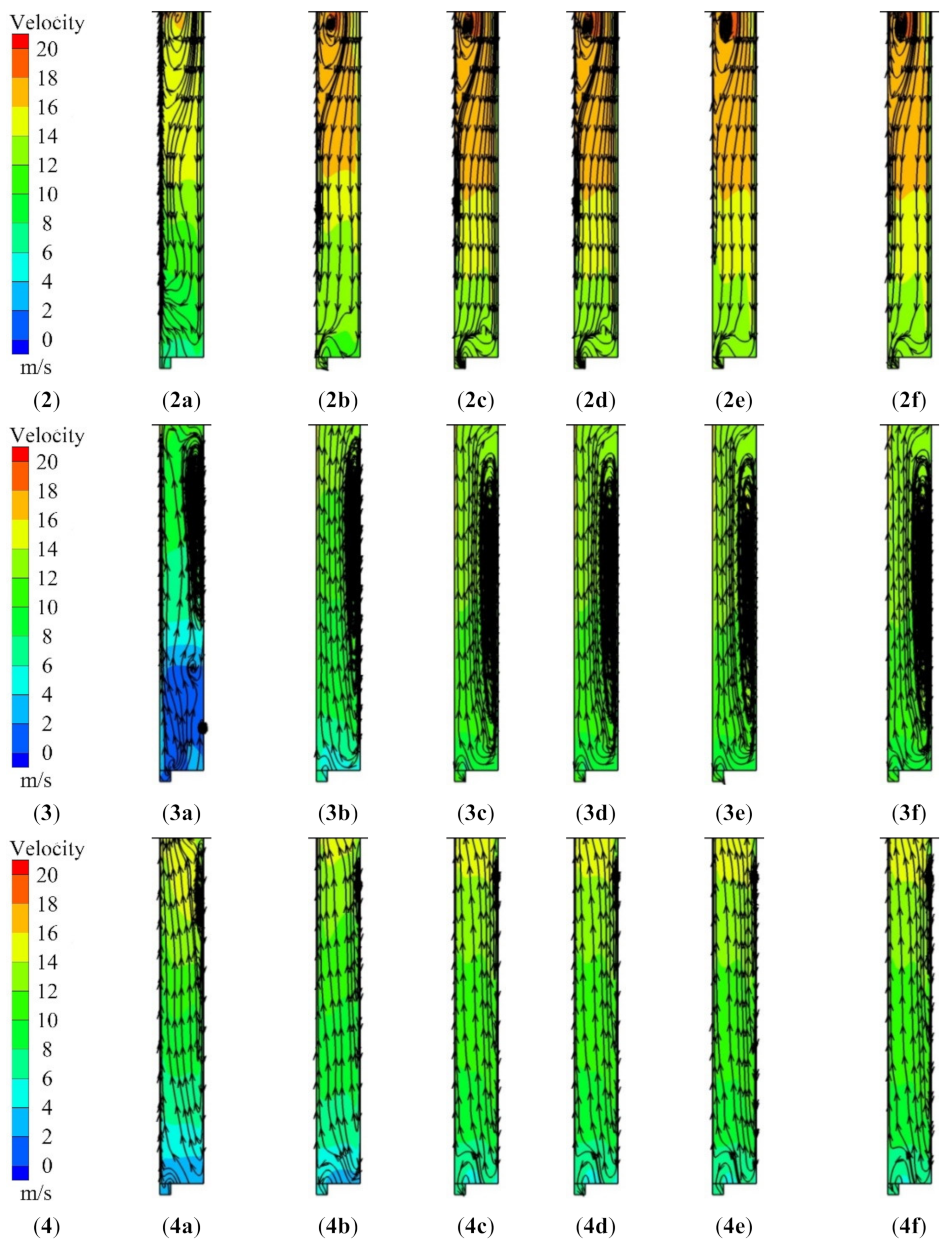
3.2. Characteristics of Flow Field in the Rear Chamber

The liquid flow velocity and streamline distribution at four angles in the rear chamber under the conditions of six different balance hole diameters are shown in Figure 6.
Figure 6 shows that at the same angle, the liquid flow velocity in the rear chamber gradually decreases along the radial direction, especially the high-speed zone near the volute (speed is greater than 18 m/s) at 90° and low velocity zone (speed less than 4 m/s) near the rear seal ring at an angle of 0°. The liquid flow speed at the same radius of the rear chamber at the same angle increases when d increases from 0 to 12 mm. Meanwhile, there is leakage of liquid flowing along the rear seal ring clearance. The structure and position of the vortex core do not change with the increase of the diameter of the balance hole, but the vortex is more obvious and the vortex strength is continuously enhanced. At an angle of 180°, the area of the vortex on the wall surface of the pump back cover gradually increases.
The liquid flow velocity of the rear chamber is significantly larger at 90°, compared with 0°, 180°, and 270°. At 0° and 90°, the rear chamber liquid is mainly sealed backward by the volute flow in the ring direction and there are vortices near the wall surface of the impeller cover and the volute. At 180° and 270°, the rear chamber liquid flows mainly from the rear seal ring toward the volute and has a vortex near the wall surface of the pump cover. The above phenomenon is caused by the angle of 90° corresponding to the first section of the volute, and that the cross-sectional area of first section is less than others (180°, 270° and 0° angles correspond to sections 3, 5, and 7 of the volute) and the fact that the first section is located at the volute tongue nearby (see Figure 2a). The flow in the volute has a large restrictive effect on the liquid flow in the chamber of the 90°, which results in a large speed and a vortex motion in the high speed region near the volute. In this paper, the non-dimensional tangential velocity v ¯ u , non-dimensional radial velocity v ¯ r and non-dimensional axial length coefficient s ¯ are introduced in Ref. [25].
v ¯ u = v u ω r
v ¯ r = v r ω r
s ¯ = s δ

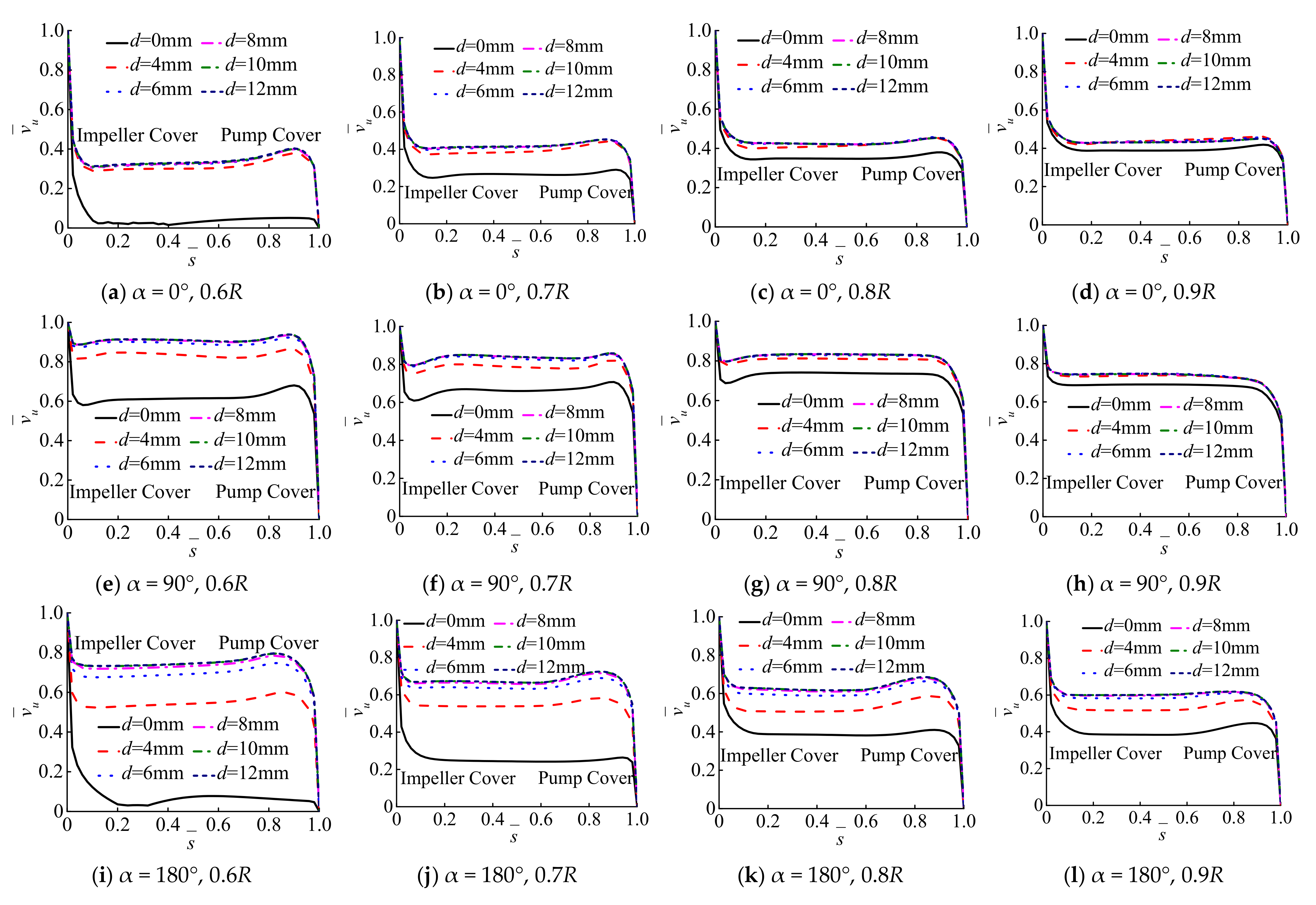
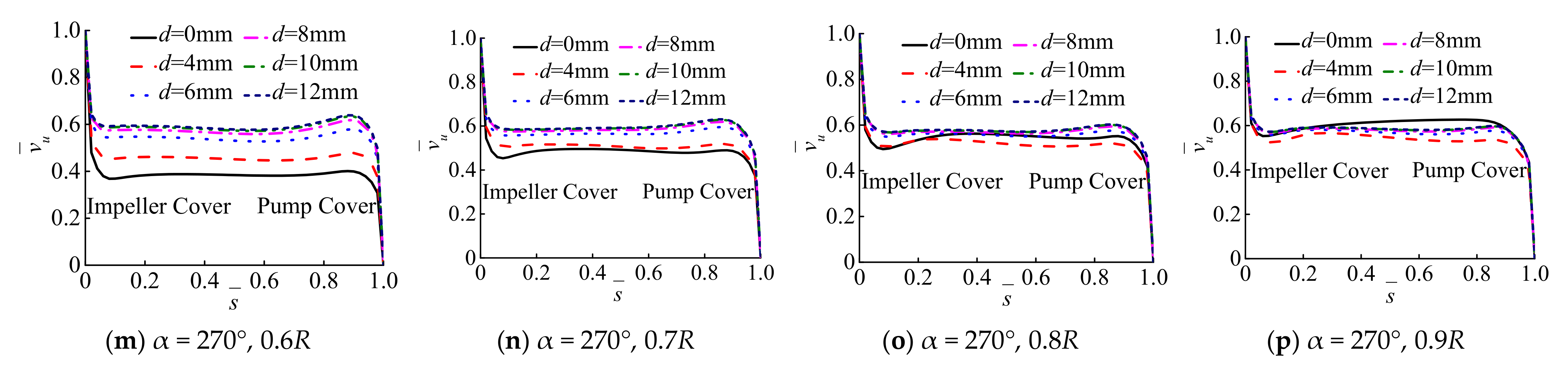
3.3. Tangential Velocity in the Rear Chamber

The rear chamber of the centrifugal pump is at the distances of 0.6R, 0.7R, 0.8R, and 0.9R (the R is radius) of angles of 0°, 90°, 180°, and 270°, respectively, when the balance hole diameter is 0–12 mm. The axial distribution curve of the non-dimensional tangential velocity is shown in Figure 7.
The tangential velocity ranges from 0.02–0.40, 0.29–0.46, 0.31–0.44, 0.32–0.45, 0.32–0.45, and 0.32–0.45 when the balance hole diameter is 0, 4, 6, 8, 10, and 12 mm. In the axial direction of 0°, 90°, 180°, and 270°, with a radius of 0.8R, the non-dimensional tangential velocity of the liquid core region ranges from 0.35–0.74, 0.40–0.81, 0.42–0.83, 0.42–0.84, 0.42–0.84, and 0.42–0.84 when the balance hole diameter is 0, 4, 6, 8, 10, and 12 mm. It shows that the non-dimensional tangential velocity of the liquid in the core area decreases along the axial direction and becomes more equal in the radial direction of the same angle. Meanwhile, it can be seen from Figure 7 that the boundary layer separation phenomenon exists. In the tangential direction of the same radius, the value of the non-dimensional tangential velocity of the liquid in the core region of the rear chamber increases first and then equals out. This is due to the fact that when the balance hole diameter is small, the rear seal ring clearance leakage amount is also small, indicating that the rear chamber pressure potential energy is small, and the kinetic energy is small as well. The pressure difference between the rear chamber and the hub chamber is large, and the pressure energy and kinetic energy of the rear chamber are large, resulting in the same radius of the tangential direction and the same angle of the radial direction of the non-dimension tangential velocity tends to be the same.
The non-dimensional tangential velocity of the liquid in the radial direction which causes the tangential direction of the same radius and the same angle approaches and is uniform, and the value is large. It is indicated that as the diameter of the balance hole increases, the pressure energy and kinetic energy of the rear chamber increase. Under the same balance hole diameter, the non-dimensional tangential velocity of the liquid in the core region of 0° with the same radius is the smallest, and the non-dimensional tangential velocity of the liquid in the core region of 90° with the same radius is the largest. When the balance hole is opened (d from 4 mm to 12 mm), in the axial directions of 0, 90, 180, and 270° of the same radius, the non-dimensional tangential velocity of the liquid in the flow core region is largely different. The non-dimensional tangential speed is the largest especially at 90°. At the 270° angle, the non-dimensional tangential velocity is the smallest, indicating that the pressure difference at the fifth section of the volute, the pressure potential energy and kinetic energy are small. Especially at 90°and 270°, when the d = 6 mm, compared with that of d = 4 mm, the circumferential velocity at the same radius increases significantly.

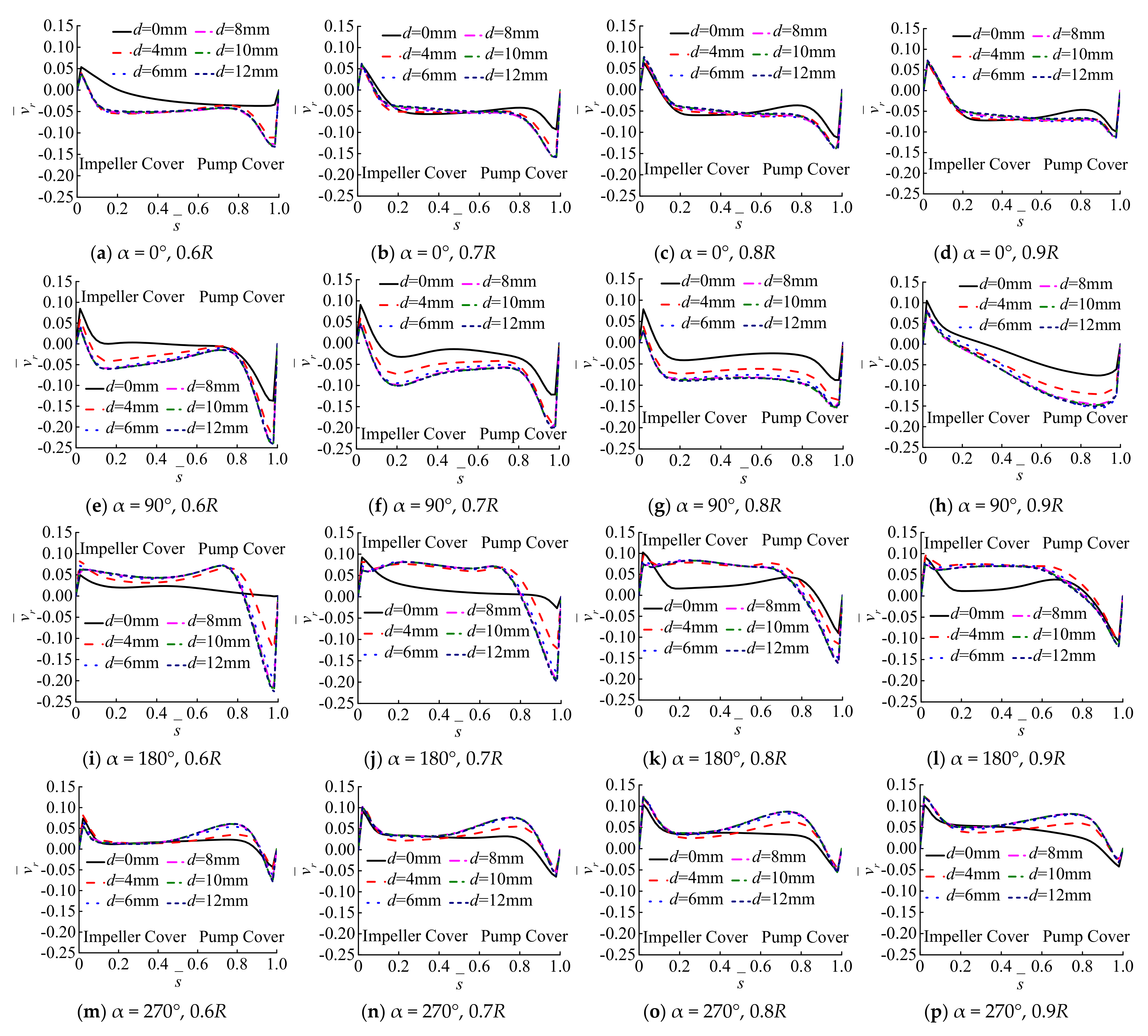
3.4. Radial Velocity in the Rear Chamber

For the six balance hole diameters (0, 4, 6, 8, 10, and 12 mm), the rear chamber of the centrifugal pump is at the 0.6R, 0.7R, 0.8R and 0.9R radii of angles 0°, 90°, 180°, and 270°. The axial distribution curve of the non-dimensional radial velocity is shown in Figure 8.
In Figure 8, when the balance hole diameter increases from 0 to 12 mm, the absolute value of the dimensionless radial velocity less than zero along the turbulent boundary layer in the axial direction near the wall surface of the pump cover gradually increases. In the axial direction of the angles of 0°, 90°, 180°, and 270° with a radius of 0.8R, the absolute value of the turbulent boundary layer near the wall surface of the pump cover increases. The leakage amount of the rear seal ring clearance and the radial leak rate of the rear chamber is larger when the diameter of the balance hole is larger. Meanwhile, the leakage mainly occurs near the boundary layer of the pump cover wall. The non-dimensional radial velocity of the 90° core region with a radius of 0.9R gradually decreases, while the liquid non-dimensional radial velocity of the 180° core region gradually increases with dimensionless axial distance, and the variation amplitude is greater than 0° and 270°. The mainstream flow effect in the volute is obvious due to the larger cross-sectional area of the volute in the 0° and 270° directions. The tongue mainly restricts the liquid flow in the areas close to the volute tongue. At the same time, the increase of the balance hole diameter has a great influence on the axial distribution of the liquid radial velocity in the rear chamber in the direction of the first and third sections of the volute, and the rear chamber in the direction of the fifth and seventh sections of the volute (see Figure 2a). The internal fluid radial velocity has less influence along the axial distribution. In the areas where the cross-sectional area of the volute is larger, the axial distribution of the liquid in the rear chamber is less affected by the balance hole diameter.

3.5. Verification of the Flow Velocity in the Rear Chamber

The PIV experiment method is compared with the hot-wire anemometer measurement data in Refs. [26,27]. It is found that the tangential and radial velocity distributions agree well at the 0.8R of the disk. In the case of there being no balance hole, the leakage flow velocity in the rear chamber region is extremely small, which can be approximated as the rotation of the rotating disk in the closed cylinder. The hot-wire anemometer measurement data of 0.8R of the rotation of the rotating disk in the closed cylinder in Refs. [26,27] is compared with the calculation data which are the mean of the four angles of 0.8R in the rear chamber. The comparison between the numerical calculation results and the experiment results is shown in Figure 9.
In Figure 9, the numerical results of the non-dimensional tangential and radial velocity distribution of the liquid flow in the rear chamber are basically consistent with the experimental results.

3.6. Disk Friction Loss of Rear Chamber

Since the balance hole diameter is changed from 0 mm to 12 mm, the liquid tangential velocity in the core region of the rear pump presents less variations along the axial direction. The axial center tangential velocity of the rear chamber can truly reflect the liquid flow due to factors such as the mainstream flow in the volute and the radical leakage flow of the clearance of seal ring. In order to calculate the disk friction loss more accurately, take the four angles in the design flow condition (0°, 90°, 180°, 270°). The average tangential velocity of the axial center of the rear chamber in the radial direction is set to be vu1, the average rotational speed uref of the impeller cover plate in the rear chamber area was 18.592 m/s, and the disk friction loss P1 was calculated as shown in Table 2.
The moment when M is generated by the outer wall surface of the impeller back shroud in the rear chamber area can be expressed and the calculation formula of disk friction loss can be written as:
M = R m R λ ρ u r e f v u 1 2 π r 2 d r
The calculation formula of disk friction loss can be written as:
P 1 = M ω
where, λ is the coefficient of friction (λ = 0.05), ρ is the density of the liquid (kg/m3), R is the rear chamber radius (m), and Rm is the radius of the rear seal ring (m).
In Table 2, when the balance hole diameter is increased from 0 mm to 8 mm under the design flow condition, the difference between the average tangential velocity of the axial center of the rear chamber is continuously increased and the mean value of the rotational speed of the impeller cover plate of the rear chamber region is reduced, and the disk friction loss is reduced. The changes of the difference between the mean value of the tangential velocity in the axial center of the rear chamber is small and the mean value of the rotational speed of the impeller cover plate in the rear chamber area is relatively small, and the disk friction loss is also small when the balance hole diameter is increased from 8 mm to 12 mm. In general, the larger the balance hole diameter, the larger the tangential speed of the rear chamber when the balance hole diameter d < 8 mm; the tangential speed of the rear chamber is basically stable, and the disk friction loss remains essentially unchanged. Among them, the disk friction loss is the smallest when the balance hole diameter is 8 mm. According to the theoretical formula, when vu = ωr/2, the friction loss power of the rear chamber area is 2.560 kW, which is smaller than the disk friction loss power of the rear chamber area of the balance hole diameter of 0 to 4 mm and larger than the balance hole diameter 8 mm. The disk friction loss powers have little change from range of balance hole diameter 6 to 12 mm in the rear chamber area. It shows that the current theoretical calculation formula or correction formula cannot calculate the influence of the balance hole diameter change on the disk friction loss at the same flow condition point, so the disk friction loss calculation formula still needs further correction.

4. Conclusions

At the same flow point, the turbulent boundary layer liquid in the rear chamber of the centrifugal pump is greatly affected by the leakage flow and has no axial symmetry. The smaller the cross-sectional area of the volute, the greater the tangential velocity of the liquid in the core area of the rear pumping chamber, and the radial leakage flows from the volute to the seal ring at 0° and 90°. When the diameter of the balance hole increases from 4 mm to 12 mm, the liquid flow in the rear chamber is restricted mainly by the mainstream flow of the volute in the larger area of the volute cross section (sections 5 and 7).
At the same radius and at the same angle, the larger the diameter of the balance hole, the larger the angular velocity of liquid rotation in the core area of the rear chamber and the greater the radial leakage velocity of the turbulent boundary layer on the wall surface of the pump cover. When the balance hole diameter is smaller than the design value, the smaller the balance hole diameter the larger the friction loss of the disk in the rear chamber area. When the balance hole diameter is larger than the design value, the disk friction loss of the rear chamber remains basically unchanged. The disk friction loss has been calculated according to the theoretical formula, and the results of the calculation was obtained under the assumption that the liquid rotates around the pump axis at half the angular velocity of the impeller don’t conform to reality. In addition, the calculation result needs to be corrected as the effect of the balance hole diameter is not considered.

Author Contributions

Conceptualization, W.D.; methodology, Z.L. and H.Z.; software, P.L.; validation, W.D. and H.Z.; formal analysis, H.Z.; investigation, W.D. and H.Z.; resources, W.D. and G.Z.; data curation, H.Z.; writing—original draft preparation, W.D. and H.J.; writing—review and editing, H.Z.; visualization, W.D.; supervision, P.L.; project administration, H.Z.; funding acquisition, W.D. All authors have read and agreed to the published version of the manuscript.

Funding

This work was supported by the scientific research foundation of National Natural Science Foundation of China (No. 52009114), China Postdoctoral Science Foundation (No. 2021M692660), Fundamental Research Funds for the Central Universities (No. 2452019015), Open Research Fund of State Key Laboratory of Hydro-power Equipment of China (No. SKLHE-ORF-202103), and Science and Technology Plan Project Funds for Shaanxi Provincial Department of Water Resources (No. 2019slkj-15).

Institutional Review Board Statement

Not applicable.

Informed Consent Statement

Not applicable.

Data Availability Statement

All data generated or analyzed during this study have been included in this article.

Conflicts of Interest

The authors declared no potential conflicts of interest with respect to the research, authorship, and/or publication of this article.

References

  1. Tan, M.G.; Lu, Y.D.; Wu, X.F.; Liu, H.L.; Tian, X. Investigation on performance of a centrifugal pump with multi-malfunction. J. Low Freq. Noise Vib. Act. Control 2020, 40, 740–752. [Google Scholar] [CrossRef]
  2. Zhu, D.; Xiao, R.F.; Yao, Z.F.; Yang, W.; Liu, W.C. Optimization design for reducing the axial force of a vaned mixed-flow pump. Eng. Appl. Comput. Fluid Mech. 2020, 14, 882–896. [Google Scholar] [CrossRef]
  3. Wang, K.; Luo, G.Z.; Li, Y.; Xia, R.C.; Liu, H.L. Multi-condition optimization and experimental verification of impeller for a marine centrifugal pump. Int. J. Nav. Archit. Ocean Eng. 2020, 12, 71–84. [Google Scholar] [CrossRef]
  4. Cheng, X.R.; Chang, Z.B.; Jiang, Y.M. Study on the influence of the specific area of balance hole on cavitation performance of high-speed centrifugal pump. J. Mech. Sci. Technol. 2020, 34, 3325–3334. [Google Scholar] [CrossRef]
  5. Nishida, M.; Nakayama, K.; Sakota, D.; Kosaka, R.; Maruyama, O.; Hyakutake, T.; Kuwana, K.; Yamane, T. Properties of a monopivot centrifugal blood pump manufactured by 3D printing. J. Artif. Organs 2016, 19, 322–329. [Google Scholar] [CrossRef] [PubMed]
  6. Dong, W.; Chen, D.Y.; Sun, J.; Dong, Y.; Yang, Z.B.; Yan, J. Influence of balance hole diameter on leakage flow of the balance chamber in a centrifugal pump. Shock Vib. 2021, 2021, 8860493. [Google Scholar] [CrossRef]
  7. Cheng, X.R.; Luo, J.H.; Xiong, B.; Jiang, Y.M. Influence of the balance hole circumferential position on the cavitation performance of the semiopen impeller centrifugal pump. Math. Probl. Eng. 2021, 2021, 4472433. [Google Scholar] [CrossRef]
  8. Wu, Y.; Chen, X.P.; Dou, H.S.; Zheng, L.L.; Zhu, Z.C.; Cui, B.L.; Khoo, B.C. Numerical simulation and analysis of flow characteristics in the front chamber of a centrifugal pump. J. Mech. Sci. Technol. 2017, 31, 5131–5140. [Google Scholar] [CrossRef]
  9. Chao, Q.; Zhang, J.H.; Zhai, J. Effects of inclined cylinder ports on gaseous cavitation of high-speed electro-hydrostatic actuator pumps: A numerical study. Eng. Appl. Comput. Fluid Mech. 2019, 13, 245–253. [Google Scholar] [CrossRef] [Green Version]
  10. Zhang, N.; Liu, X.K.; Gao, B.; Xia, B. DDES analysis of the unsteady wake flow and its evolution of a centrifugal pump. Renew. Energy 2019, 141, 570–582. [Google Scholar] [CrossRef]
  11. Olimstad, G.; Osvoll, M.; Finstad, P.H.E. Very low specific speed centrifugal pump-hydraulic design and physical limitations. J. Fluids Eng. 2018, 140, 071403. [Google Scholar] [CrossRef]
  12. Will, B.C.; Benra, F.K.; Dohmen, H.J. Investigation of the flow in the impeller side clearances of a centrifugal pump with volute casing. J. Therm. Sci. 2012, 21, 197–208. [Google Scholar] [CrossRef]
  13. Salvadori, S.; Marini, A.; Martelli, F. Methodology for the residual axial thrust evaluation in multistage centrifugal pumps. Eng. Appl. Comput. Fluid Mech. 2012, 6, 271–284. [Google Scholar] [CrossRef] [Green Version]
  14. Lefor, D.; Kowalski, J.; Kutschelis, B.; Herbers, T.; Mailach, R. Optimization of axial thrust balancing swirl breakers in a centrifugal pump using stochastic methods. In Proceedings of the ASME 2014 4th Joint US-European Fluid Engineering Division Summer Meeting, Chicago, IL, USA, 3–7 August 2014. FEDSM2014-21262. [Google Scholar]
  15. Ladouani, A.; Nemdili, A. Influence of reynolds number on net positive suction head of centrifugal pumps in relation to disc friction losses. Forsch. Ing. 2009, 73, 173–182. [Google Scholar] [CrossRef]
  16. Wang, C.; Shi, W.D.; Wang, X.K.; Jiang, X.P.; Yang, Y.; Li, W.; Zhou, L. Optimal design of multistage centrifugal pump based on the combined energy loss model and computational fluid dynamics. Appl. Energy 2017, 187, 10–26. [Google Scholar] [CrossRef]
  17. Barrio, R.; Parrondo, J.; Blanco, E. Numerical analysis of the unsteady flow in the near-tongue region in a volute-type centrifugal pump for different operating points. Comput. Fluids 2010, 39, 859–870. [Google Scholar] [CrossRef]
  18. Kim, E.; Palazzolo, A. Rotordynamic force prediction of a shrouded centrifugal pump impeller-part I: Numerical analysis. J. Vib. Acoust. 2016, 138, 031014. [Google Scholar] [CrossRef]
  19. Huang, B.; Zeng, G.T.; Qian, B.; Wu, P.; Shi, P.L.; Qian, D.Q. Pressure fluctuation reduction of a centrifugal pump by blade trailing edge modification. Processes 2021, 9, 1408. [Google Scholar] [CrossRef]
  20. Sojoudi, A.; Nourbakhsh, A.; Shokouhmand, H. Establishing a relationship between hydraulic efficiency and temperature rise in centrifugal pumps: Experimental study. J. Hydraul. Eng. 2018, 144, 04018011. [Google Scholar] [CrossRef]
  21. Li, W.; Jiang, X.P.; Pang, Q.L.; Zhou, L.; Wang, W. Numerical simulation and performance analysis of a four-stage centrifugal pump. Adv. Mech. Eng. 2016, 8, 1687814016673756. [Google Scholar] [CrossRef] [Green Version]
  22. Li, Y.B.; He, C.H.; Li, J.Z. Study on flow characteristics in volute of centrifugal pump based on dynamic mode decomposition. Math. Probl. Eng. 2019, 2019, 2567659. [Google Scholar] [CrossRef]
  23. Liu, H.L.; Liu, M.M.; Bai, Y.; Dong, L. Effects of mesh style and grid convergence on numerical simulation accuracy of centrifugal pump. J. Cent. South Univ. 2015, 22, 368–376. [Google Scholar] [CrossRef]
  24. Casimir, N.; Zhu, X.Y.; Hundshagen, M.; Ludwig, G.; Skoda, R. Numerical study of rotor-stator interaction of a centrifugal pump at part load with special emphasis on unsteady blade load. J. Fluids Eng. 2020, 142, 081203. [Google Scholar] [CrossRef]
  25. Dong, W.; Chu, W.L. Numerical investigation of fluid flow mechanism in the back shroud cavity of a centrifugal pump. J. Appl. Fluid Mech. 2018, 11, 709–719. [Google Scholar] [CrossRef]
  26. Fu, Y.X.; Yuan, J.P.; Yuan, S.Q.; Pace, G.; d’Agostino, L.; Huang, P.; Li, X.J. Numerical and experimental analysis of flow phenomena in a centrifugal pump operating under low flow rates. J. Fluids Eng. 2014, 137, 011102. [Google Scholar] [CrossRef]
  27. Seelig, T.; Harlander, U.; Gellert, M. Experimental investigation of stratorotational instability using a thermally stratified system: Instability, waves and associated momentum flux. Geophys. Astrophys. Fluid Dyn. 2018, 112, 239–264. [Google Scholar] [CrossRef]
Figure 1. The solid model of centrifugal pump.
Processes 10 00613 g001
Figure 2. The calculation model diagram. (a) Planar graph; (b) axial plane graph.
Processes 10 00613 g002
Figure 3. The grid of the centrifugal pump.
Processes 10 00613 g003
Figure 4. Grid-independence verification.
Processes 10 00613 g004
Figure 5. Simulation results of external characteristic parameters of centrifugal pump.
Processes 10 00613 g005
Figure 6. Radial cross-section liquid velocity and flow line of the rear chamber. (1) 0°; (2) 90°; (3) 180°; (4) 270°; (1a,2a,3a,4a) d = 0 mm; (1b,2b,3b,4b) d = 4 mm; (1c,2c,3c,4c) d = 6 mm; (1d,2d,3d,4d) d = 8 mm; (1e,2e,3e,4e) d = 10 mm; (1f,2f,3f,4f) d = 12 mm.
Processes 10 00613 g006aProcesses 10 00613 g006b
Figure 7. Axial distribution of non-dimensional tangential velocity.
Processes 10 00613 g007aProcesses 10 00613 g007b
Figure 8. Axial distribution of non-dimensional radial velocity.
Processes 10 00613 g008
Figure 9. Comparison of numerical results and test results.
Processes 10 00613 g009
Table 1. Design parameters of single-stage single-suction centrifugal pump.
DescriptionParameterValue
Design flow rate (m3/h)Qd200
Head (m)H32
Efficiency (%)ƞ81
Rotating speed (r/min)n1450
Specific speedns87
Shroud diameter (mm)D325
Front sealing ring diameter (mm)Dl140
Back sealing ring diameter (mm)Dm165
Sealing ring radial clearance (mm)b0.22
Balance hole diameter (mm)d8
Balance holes numberz16
Blade numberz26
Table 2. The calculation results of disk friction loss.
d/(mm)04681012
vu1/(m/s)6.3287.05010.51011.33810.83711.259
P1/(kW)4.4553.9461.9351.5591.7561.593
Publisher’s Note: MDPI stays neutral with regard to jurisdictional claims in published maps and institutional affiliations.

