Article

Study on Gas-Solid Heat Transfer and Decomposition Reaction of Calcination Process in an Annular Shaft Kiln Based on the Finite Volume Method

School of Metallurgy, Northeastern University, No. 3-11, Wenhua Road, Heping District, Shenyang 110819, China
*
Author to whom correspondence should be addressed.
Processes 2022, 10(4), 648; https://doi.org/10.3390/pr10040648
Submission received: 18 February 2022 / Revised: 19 March 2022 / Accepted: 24 March 2022 / Published: 26 March 2022

Abstract

:
As an excellent reducing agent, lime has an important role in the steel production process. Annular Shaft Kiln (ASK) has been widely used in the lime production industry for its low cost, low footprint, high chemical activity, easy construction, and easy maintenance. Due to the high temperature generated inside ASK during operation, it is hard to observe the limestone decomposition process and the field distribution in the lime kiln. The simulation analysis of temperature field, velocity field and decomposition field in the limestone calcination process by CFD provides practical guidance for future lime product quality control, ASK design and operation parameters’ control. This study is based on an ASK that was put into production. Based on the finite volume method, this paper combines the porous medium model and the shrinking core model to establish a set of mathematical models that can describe the temperature and flow field distribution inside the ASK, as well as the limestone decomposition process and the heat and mass transfer process inside the ASK. According to the feedback from the production site, the mathematical model is in good agreement with the production results.

1. Introduction

In the process of steel smelting, lime can shorten the smelting time, reduce slag production, ensure the quality of steel and reduce the role of damage to the furnace lining; lime can also be mixed with iron ore powder in the sintering process after sintering smelting, so that the smelting process heats up faster. The roasting speed of pellets in the furnace kiln is also significantly accelerated, and the sintering output is subsequently increased [1,2,3].
Lime, also known as quicklime, used in metallurgical processes, is calcined from limestone by the heat generated by burning fuel, accompanied by the generation of carbon dioxide and the final formation of white lime particles. The common classification of lime kilns is divided by kiln structure, which can be divided into horizontal and vertical kilns.
Annular Shaft Kiln (ASK) is a type of shaft kiln, and the most important feature of this kiln is the way the combustion chamber is configured. ASK is equipped with two rings of combustion chambers (inner-ring combustion chamber and outer-ring combustion chamber) inside the kiln. The calcination zone, and a schematic diagram of the combustion chamber and kiln structure are shown in Figure 1.
The ASK has a circular cross-section and the main part of the kiln is ring-shaped. The combustion chamber is divided into an inner ring and an outer ring, which ensures the uniformity of material calcination. During the calcination process, limestone enters from the top of the kiln, moves in the direction of gravity inside chamber, and passes through the preheating zone, the calcination zone and the cooling zone in turn, so that calcium carbonate is heated and decomposed, and finally pushed out from the hydraulic cylinder of the discharge platform. The combustion fuel gas enters the kiln and is removed from the top of the kiln through the chamber, before finally being drained by the action of the induced draft fan at the top of the kiln.
The ASK is suitable for calcining limestone, pellets and other materials that do not change in volume, and is an improved type of traditional shaft kiln. Similar to the traditional shaft kiln, the ASK has the advantages of a small floor space, high activity in the finished products, a simple structure, low heat consumption, and more types of supporting fuels, etc., and also has the characteristics of low cost, uniform calcination, compatibility with small-grain-size limestone, good transformation, etc.
The shrinking core model is a more widespread mathematical model, used to describe the current behavior of limestone decomposition, which was first proposed by Szekely [4]. This theory understands limestone decomposition as a gas–solid heat and mass transfer process and fits the function between the decomposition rate and the temperature at the reaction interface through experimental data. Hills [5] analyzed the variation in particle temperature and limestone mass during the decomposition of individual limestone particles using the heat balance method and concluded that the reaction rate of limestone during calcination is not only related to the reaction interface temperature and reaction area, but also to the rate of heat and mass transfer between the limestone reaction interface and the environment. Escardio et al. [6] performed calcination tests on 0.45–3.6 mm grain size limestone, placed at different calcination temperatures with different CO2 concentrations, and fitted the degree of decomposition as a function of temperature by building a particle lattice model, which is in agreement with the experimental results. Khinast et al. [7] performed decomposition rate experiments using thermogravimetry for different ambient pressures and different reactant particle sizes, obtained the equation for the reaction rate versus CO2 concentration by fitting the reaction particle model, and indicated that the reaction rate varies exponentially with CO2 concentration.
Lu Shangqing et al. [8] studied the decomposition of limestone particles by combining the shrinking core model, thermodynamic properties and reaction kinetics, evaluated the effect of reaction conditions on the reaction temperature and the reaction rate by varying the particle size, heat, structure, and decomposition pressure of limestone particles, and concluded that the decomposition rate and decomposition temperature of calcium carbonate are not fixed values, but change with the value of the microstructure of calcium carbonate. Chen Hongwei et al. [9] studied the decomposition behavior of limestone by thermogravimetric experiments, which showed that temperature is the key factor affecting the decomposition reaction rate of limestone particles, and the decomposition reaction rate will be greatly increased by increasing the temperature. The concentration of carbon dioxide in the environment has an inhibitory effect on the rate of limestone decomposition reaction, and it is also suggested that the larger the particle size of the limestone particles, the slower the reaction rate to the middle and later stages. Feng Yun et al. [10] summarized previous research on calcium carbonate decomposition kinetics and introduced the idea that the suspended state would be a better state at which to promote the uniform decomposition of limestone, and concluded that a circulation device with a high solid-to-gas ratio would provide a more suitable decomposition reaction device.
Senegačnik [11,12] applied the kinetics of limestone decomposition to an ASK and, by analyzing the calcination characteristics and temperature distribution of calcium carbonate in ASK, the decomposition temperature of limestone in the chamber was inferred to be approximately 1093–1103 K. The gas–solid heat exchange situation led to the conclusion that heat is first transferred from the fuel gas to the surface of limestone particles by convective heat exchange, and then heat is transferred to the surface of limestone particles by convective heat transfer. Then, the heat passes through the porous calcium oxide layer of the product to the decomposition interface by heat conduction and supplies the limestone needed to continue decomposition.
Based on the ASK in operation, Li Jingwang et al. [13] pointed out the problems and deficiencies that still exists in this type of kiln and gave suggestions for its modification and optimization.
Senegačnik et al. [14] proposed the use of lime kiln exhaust gas and cooling of the combustion chamber flame, which can recover the heat in the fuel gas and ensure the activity of quicklime. The technique also has the positive effect of extending the kiln life. Sagastume et al. [15,16] analyzed the thermal performance of the lime kiln using the worm-efficiency, highlighting the performance of a new direction for the analysis of lime kiln performance.
Cheng et al. [17,18] used the shrinking core model as the basis to find the gas–solid temperature profile inside the ASK using numerical simulation and analyzed the limestone decomposition rate related to the limestone type. Bluhm-Drenhaus [19] and Krause [20] combined the finite-volume method (FVM) with the finite-element method (FEM) to simulate the temperature field of the gas–solid flow inside the lime kiln and calculated the trajectory of the particles in the kiln with the flow process of the fuel gas. Ning Jingtao [21] studied the calcination of fine limestone using a shrinking core model and confirmed that 1200~1473 K is a more desirable calcination temperature for limestone.
The coupled simulation of discrete-element method (DEM) and finite-volume method (CFD) can solve the stacked bed problem in lime kilns, where the DEM model solves the limestone decomposition behavior while the CFD model simulates the gas–solid two-phase heat exchange and the pressure drop in the stacked bed. Mikulčić et al. [22] used this coupled approach to study the cement industry for CO2 emissions. Meanwhile, a two-energy equation model based on a porous media model was developed by Long Huilong et al. [23] to simulate the gas–solid chemical reaction in a non-stationary manner, which is in agreement with the experimental results.
Shanshan Bu et al. [24] studied the effect of three particle contact models on heat transfer in a stacked bed and found that the three particle contact models have a large influence on the calculation results in turbulent flow. Liu et al. [25] used a gas-burnt lime shaft kiln as a research object and solved the temperature field inside the lime kiln using a local non-thermal equilibrium model.
The proposed predictive control method can ensure that the output value of the calcination zone temperature of the lime rotary kiln is fast and stable to track the change in the reference value [26]. The aim of Reference [27] was to build a regression model for each of the three prime variables (gas consumption, SO2, and NOx emissions) in a lime kiln employed in the paper-manufacturing process using the multivariate adaptive regression splines (MARS) method in combination with the artificial bee colony (ABC) technique. The objective of Reference [28] was to evaluate the influence of electric arc furnace dust (EAFD) and lime kiln waste (LKW) in the hydration process of Portland cement pastes, and their influence on setting time and hydration heat. The outstanding work on the methodology includes the solution to the radiative heat transfer, convective mass transfer, and a method to measure the extent to which wall effects on the radial temperature distribution [29] extend to the modeling and control aspects of the lime kiln process. Thus, Reference [30] deals with issues related to the determination of the optimal specific fuel consumption for burning limestone from a particular deposit. Other influential work includes [31] an experimental validation of the thermal mass balance and porous media model on lime kilns were studied.
In the simulation research into lime kiln, most studies only solve the gas–solid two-phase temperature field inside the lime kiln, and there is a relative lack of research on the calculation of reaction heat and decomposition rate combined with the shrinking core model; in the simulation of ASK, the side-wall effect is often ignored, which affects the thermal performance of ASK; in the selection of particle size, scholars only carry out simulations of single-particle-size limestone, and there is a lack of research on the effect of mixed-particle-size calcination. In terms of particle size selection, domestic and foreign scholars have only conducted simulation studies of single-size limestone, and research on the calcination effect of mixed particle size is lacking.
The temperature distribution and limestone decomposition inside the lime kiln during high temperature operation is not yet known, due to the available observation and measurement techniques. Using Finite-Volume Method (FVM), the state inside the kiln can be restored, based on the flow field, the temperature field and the decomposition field. Afterwards, the lime kiln structure, such as the location of the fuel gas inlet and the kiln height, can be reasonably changed according to the field distribution. Production optimization can also be achieved by controlling the thickness of the material layer and the size of the raw material particles. Lime kiln is a piece of equipment with high energy consumption and high output in industrial production; the purpose of this study is to investigate the complex heat and mass transfer process in ASK and to analyze the influence of various operating conditions and structural parameters on the calcination results to provide a theoretical basis for practical production.

2. Models Introduction and Operating Conditions

2.1. Mathematical Models

Ergun equation:
| p | L = 150 μ ( 1 γ ) 2 D p 2 γ 3 v + 1.75 ρ ( 1 γ ) D p γ 3 v 2
1 α = 150 ( 1 γ ) 2 D p 2 γ 3
C 2 = 3.5 ( 1 γ ) D p γ 3
The shrinking core model assumes that the reactants are spheres, that heat is supplied uniformly from all directions, and that the chemical composition of the raw materials is uniform.
r CaCO 3 t = k M CaCO 3 ρ CaCO 3 R D
R D = k D ( p e q p co 2 )
k D = 0.0001 T p exp ( 4026 / T p ) Y T . C
p eq = 101325 exp [ 17.74 0.00108 T i + 0.332 log ( T i ) 22020 / T i ]
Y T . C = { 480 T P 958 T P > 1150 K 2.5 T P 1150 K
λ = 4 π λ 1 λ 2 λ 1 ( 1 r c 1 1 r c 2 . m ) + λ 2 ( 1 r c 1 . m 1 r c 1 ) .
Limestone decomposition rate is the volume fraction of decomposed calcium carbonate:
X S = 1 r c 2 3 r c 1 3
The temperature equations for gassolid convective heat transfer, internal and external particle heat conduction, and between solid particles:
t [ φ CaCO 3 ρ i c p i T i ] + ( v down φ CaCO 3 ρ i c p i T i ) = λ ( 1 γ ) ( T o T i ) / V s k Q D Δ H R
Q D = ( 1 γ ) 4 π r c 1 2 V p × R D
Energy equation of the external particle (calcium oxide):
t ( φ CaO ρ o c p o T o ) + ( v d o w n φ CaO ρ o c p o T o ) = ( ( k CaO + e b ) T o )   + a v h v ( T g T o ) λ ( 1 γ ) ( T o T i ) / V s
The radiation equivalent thermal conductivity treatment of porous media used for radiation between solids [32]:
e b = 16 σ T o 3 / ( 3 β )
The convective heat transfer coefficient h v is approximately calculated by flow-across tube bundle model in the heat exchanger model [33], which is calculated as follows:
h v = N u λ g l z
N u = P r 1 / 3 1.6274 R e 0.575 γ
l z = 0.0178 ρ 0.596
R e = ρ g D p u μ
P r = ν / a
a = λ g ρ g c p g
a v = ( 1 γ ) × S p V p
The gas energy equation:
t ( γ ρ g c p g T g ) + ( γ v ρ g c p g T g ) = ( k g T g ) + a v h v ( T o T g )
ε = ( 1 M CaO / ρ CaO M CaCO 3 / ρ CaCO 3 ) × X S
φ g = ( 1 γ ) ε + γ
φ CaCO 3 = ( 1 γ ) × ( 1 X S )
φ CaO = 1 φ g φ CaCO 3
The following assumptions are made in this study: ① the heat dissipation from the kiln wall of the lime kiln is ignored; ② the particles are treated as pure calcium carbonate without other impurities; ③ all combustion chambers are considered to have the same flow rates; ④ the effect of gas on solids’ movement is also not considered.

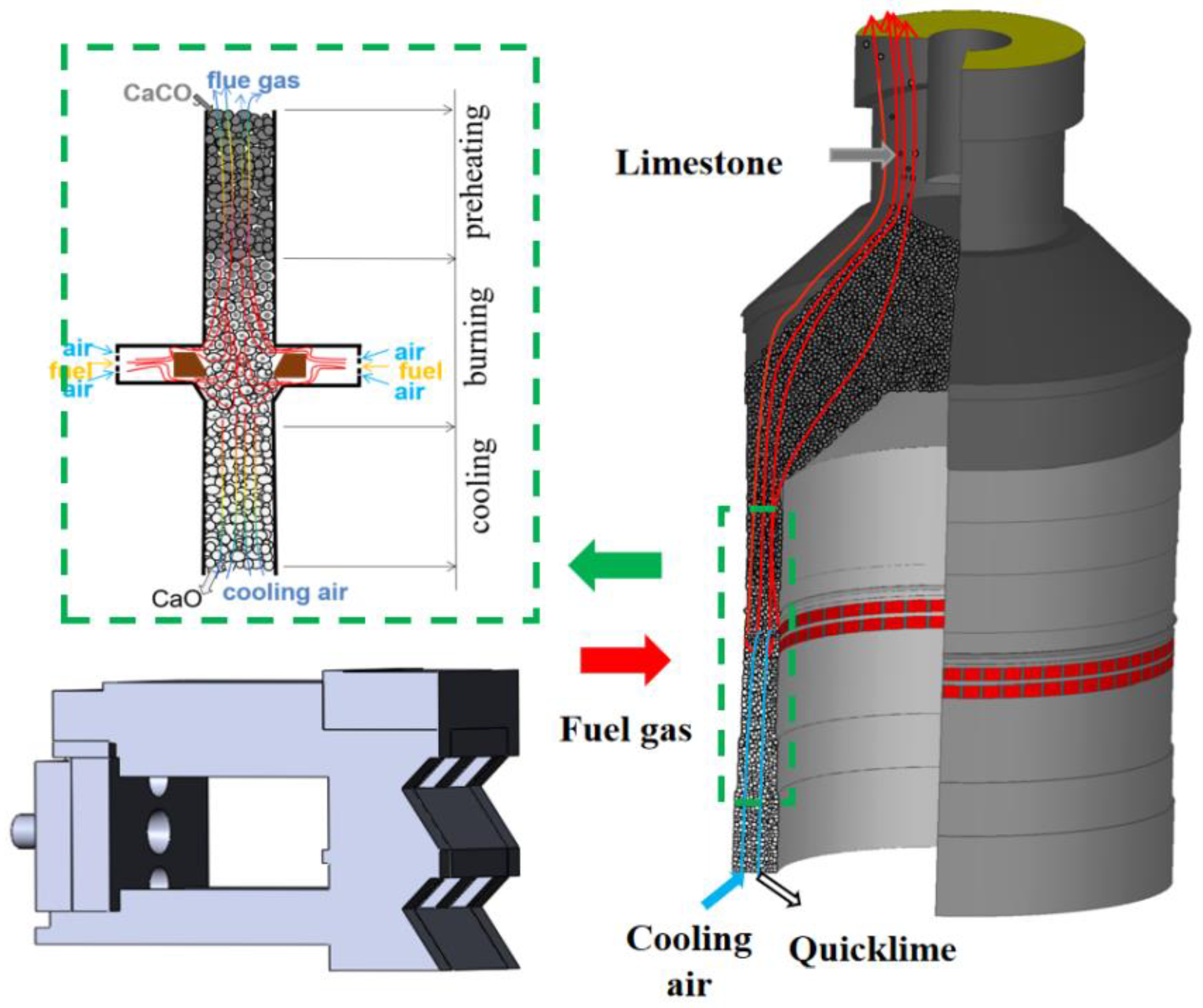
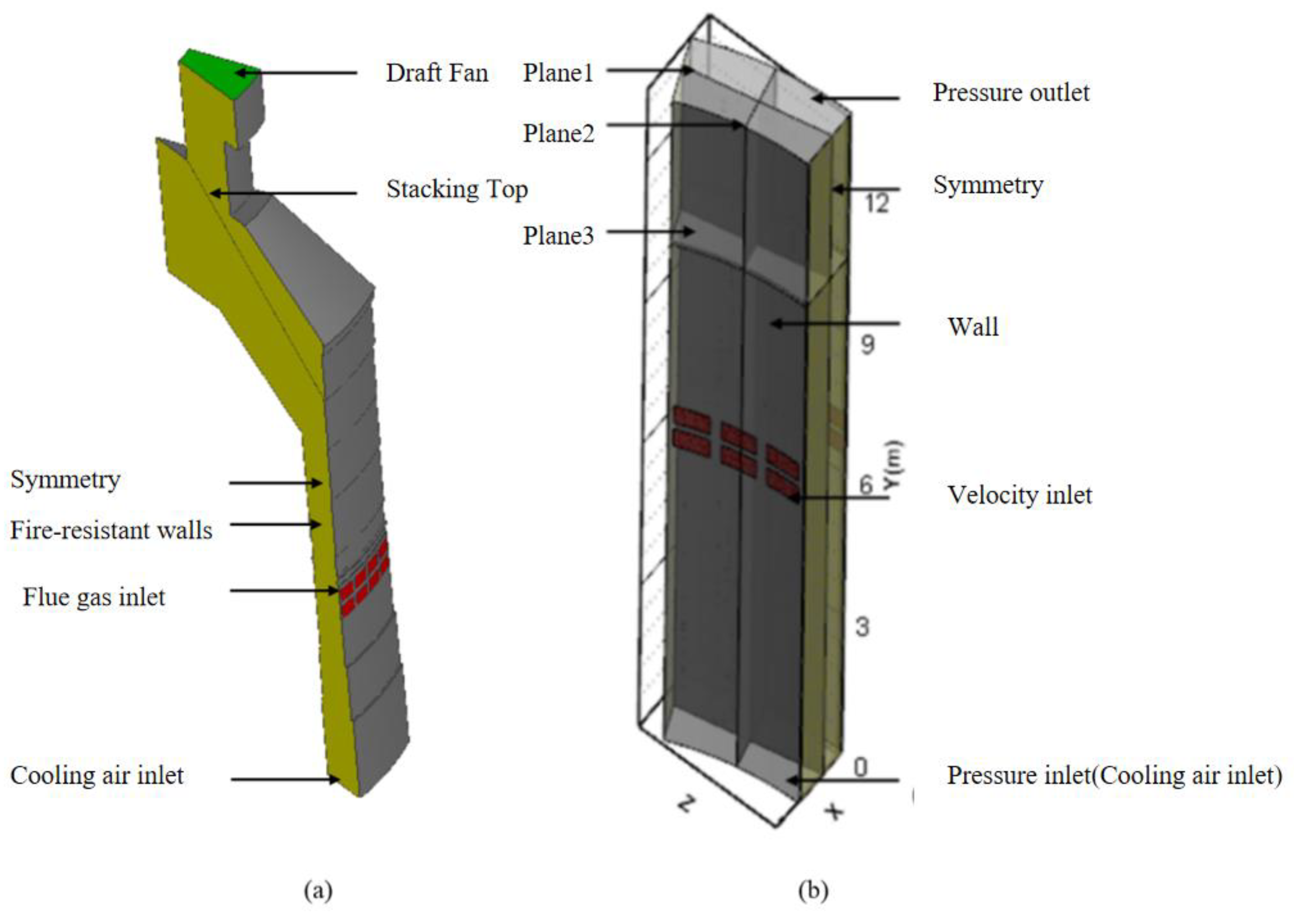
2.2. Physical Model and Boundary Conditions

The ASK adopts a symmetrical structure of inner and outer rings, with 48 combustion chambers set at equal intervals in the inner ring and 64 combustion chambers in the outer ring. To facilitate the calculation, 1/16th of the real model was taken for modeling to ensure that three combustion chamber sections were located in the inner ring and four combustion chamber sections in the outer ring. The kiln height was 22 m. The calculation domain and boundary conditions are shown in Figure 2. Since the gassolid heat exchange region occurs in the chamber and the stacking region directly above the chamber, the simplified models for calculating the temperature field and the decomposition rate are shown in Figure 2b. The kiln was equipped with an exhaust fan at the top of the kiln, which provides −5200 Pa pressure to draw out the kiln tail gas; the top of the kiln also served as an inlet for the limestone, which was formed of nearly spherical calcium carbonate particles, often entering the kiln at room temperature; the individual particles pass through the kiln in about 47.2 h. The conditions after the combustion of fuel and combustion air in the combustion chamber were used as the initial conditions for entering the lime kiln inlet.
The simulation of the calculation domain for structural grid division, after the grid-independent verification, had a flow field calculation grid number of about 580,000, and a calcination simulation calculation domain grid of about 450,000. The specific sizes of the calculation domain and part of the material properties were as shown in Table 1.
The specific heat capacity of each component of calcium oxide, calcium carbonate, and fuel gas used in the simulation varies with the temperature of each substance, and the values are shown in Table 2.
The gas density was calculated using the ideal gas equation, which is related to the atmospheric pressure, the relative molecular mass of the gas and its temperature, as follows:
ρ i = p op / ( R M i T )
The above equation indicates the ambient pressure of ASK; R indicates the gas constant 8.314 J/(molK); T indicates the gas temperature. This equation allows for the calculation of gas density for lime kilns of different altitudes.
The fuel gas inlet had a velocity inlet of 1.224 m·s−1 and the inlet temperature was about 1473 K to prevent lime becoming hard-burnt and the destruction of lime activity. The pressure inlet was set for the kiln cooling air inlet. The composition of fuel gas composition parameters is listed in Table 3. This was directly connected to the atmosphere, and the pressure value was the local atmospheric pressure. Cooling air was introduced into the kiln through a negative-pressure environment inside the kiln. Heat dissipation from the walls was not considered, so wall insulation was provided.
In the process of solving the equations, the semi-implicit method of coupled pressure equations (referred to as the SIMPLE algorithm) was used to solve the coupled velocity and pressure problem; two equations in the turbulence equations were solved in the first-order windward difference format, and the remaining equations were treated by the second-order windward difference; the convergence factor of each equation was set to 106.

3. Calcination Simulation Process

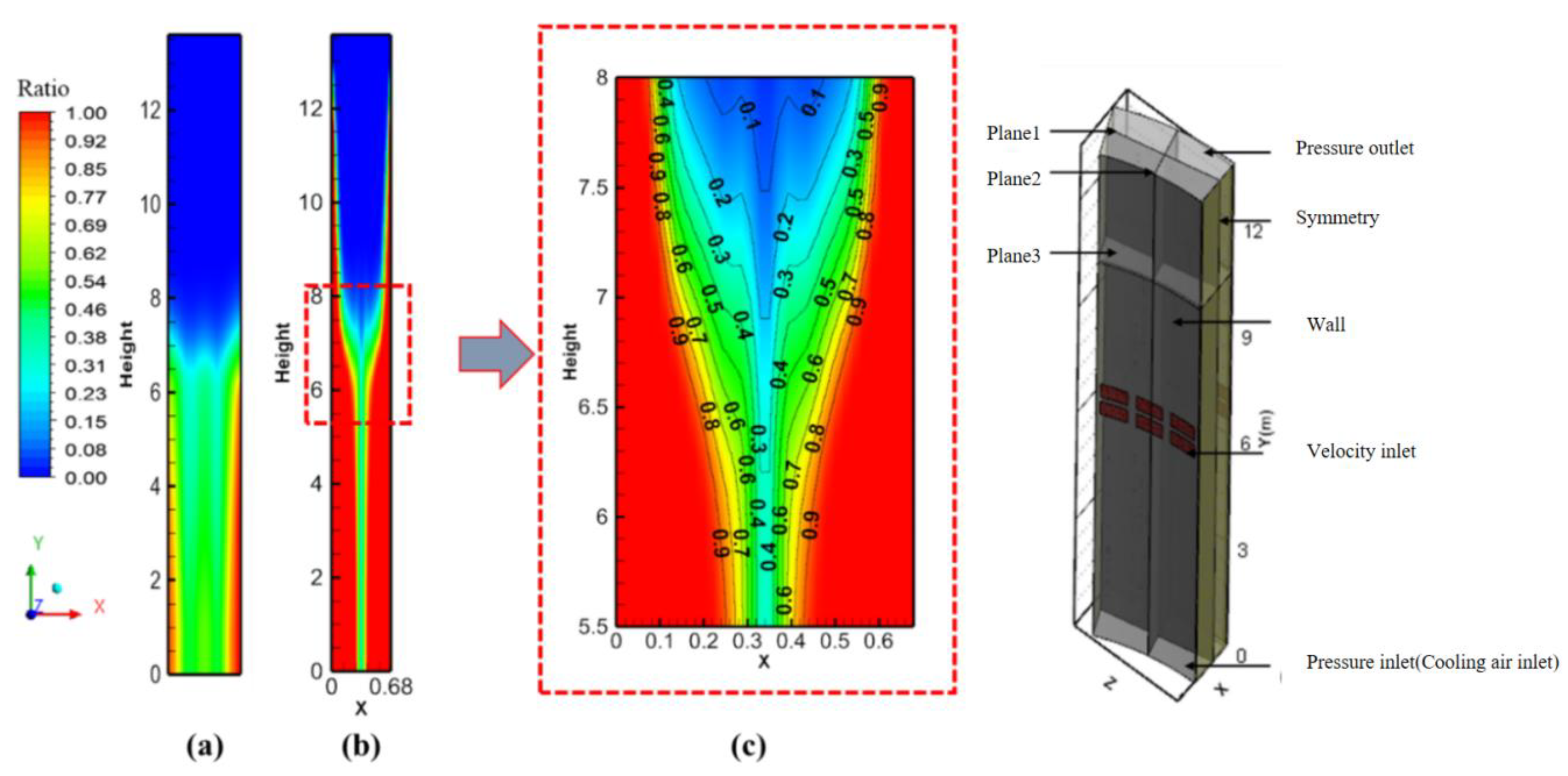
3.1. Flow Field and Temperature Field Analysis

The simulation of the flow field of the ASK with the filling material is shown in Figure 3; the gas flow velocity within the width of one particle size near the wall was very large due to the side wall effect at an inlet velocity of 1.224 m·s−1, while the flow velocity was relatively uniform in the central region of the chamber. Therefore, it can be seen that the flow rate of the heated fuel gas passing through the sidewall was larger after entering the kiln, and a large amount of heat will be located in this region. The pressure drop from the combustion chamber to the kiln roof was about 5030.7 Pa, and the measured pressure in the combustion chamber was −169.3 Pa, which matches the actual measured value in the field.
The gas and solid temperature fields, and the enlarged cross-section of the combustion chamber, are shown in Figure 4. The gas and solid temperatures were highest near the combustion chamber, reaching 1473 K. At the height of the combustion chamber, the temperature in the centre of the chamber only stayed at the decomposition temperature of 1073 K due to insufficient heat, and the gas temperature near the side walls was higher than the rest of the height due to the side wall effect, which has a higher flow rate.
Four height positions in the chamber were selected: y = 0.1 m; y = 6.5 m; y = 11 m; y = 13.3 m, for the analysis of the gas and solid temperature, as shown in Figure 5. At the the quicklime outlet position, the solid temperature was about 728 K; near the combustion chamber, the gas- and solid-phase temperature were highest and the temperature gradient was the smallest; at the top position of chamber, the gas and solid temperature gradients were the largest and this was the area where the limestone warmed up rapidly; at the top of the chamber, the fuel gas temperature near the side wall was about 1050 K and the temperature at the rest of the positions was about 590 K. A large amount of heat was located near the side wall and the overall average temperature was about 623 K, which is similar to the overall average temperature of around 623 K, in general agreement with the fuel gas temperature measured on-site at the induced-draft fan (around 573 K).

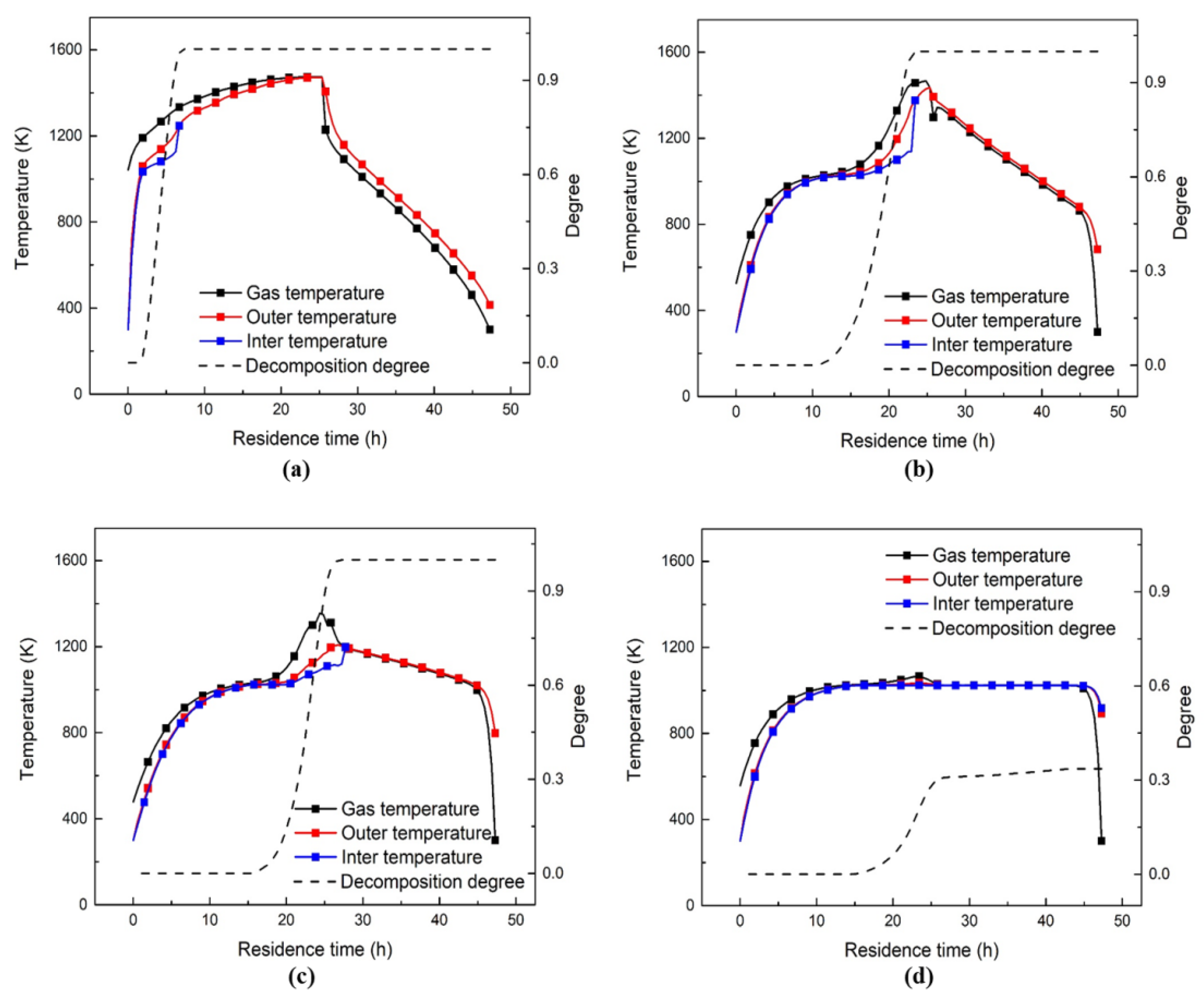
3.2. Decomposition Analysis

Two planes were selected, as shown in Figure 6 (plane1 represents the circumferential cross-section of the central area of the chamber and plane2 represents the radial cross-section). From plane2, it can be seen that the side wall effect has a clear influence on the calcination process. The limestone near walls quickly decomposes in the kiln, whereas, in the central area, the quicklime outlet, there were approximately four or five 30-mm limestones that were not completely decomposed, leaving a channel in the decomposition field. Plane1 represents the incomplete decomposition in the central area, where the decomposition rate of limestone ranged from only 30% to 50%. As the inner and outer ring combustion chambers are not perfectly symmetrical, the concentration of heat in the combustion chamber causes inconsistent decomposition in the same circumferential section, but has a negligible effect on the overall calcination results.
To clearly understand the decomposition process, four cross-sections were selected for the results analysis: y = 0.1 m; y = 6.1 m; y = 7.4 m; y = 9 m, as shown in Figure 7. In the outlet cross-section, the decomposition was not completed, and the decomposition rate of the limestone under this condition reached 92.7%, with an error of only 0.863% compared to reality (93.5%). In contrast, in the cross-section at y = 9 m, the sidewall effect is more obvious: in the range of one particle size, the limestone completely decomposed; only gas and solid heat exchange occurred, while decomposition occurred less in the centre. It can be seen that the decomposition process was relatively uniform, with a similar limestone decomposition temperature on the inner and outer sides, and had a good calcination effect on limestone of 30 mm.
At a production rate of 200 t/d, the effect of the ASK side wall effect is very obvious. To summarise the influence of the side wall effect in detail, four locations within the chamber were selected: 0.015 m off the wall (near the wall); 0.1 m off the wall; 0.2 m off the wall; and 0.34 m off the wall (chamber centre), and the variation in gas, inner and outer core temperatures and the decomposition rate with residence time during the fall of limestone at these four locations was analyzed. The results are shown in Figure 8. In Figure 8a, the decomposition of the limestone enters the chamber and is fully completed after a drop of about 5 h (a drop of about 1.4 m). After a short period of preheated decomposition, the limestone continued to absorb heat and warm up, so the fuel gas temperature needs to be controlled to prevent the lime activity from being destroyed. After passing through the combustion chamber cross-section, quicklime cools down rapidly by coming into contact with the cooling air.
Figure 8b is similar to Figure 8c: within 12–16 h of entering the chamber, the gas and solid temperature difference is relatively large, and the limestone is preheated to the decomposition temperature, while, within the next 10 h, the limestone decomposes while absorbing heat, and rapidly and completely decomposes near the cross-section of the combustion chamber before finally being cooled by air.
Figure 8d shows that the decomposition rate of the exported limestone is only 30%, while the limestone solid temperature remained at the decomposition temperature for a long time. It is worth noting that some of the decomposition continued after passing through the combustion chamber, due to the heat transfer between the lateral particles transferring high temperatures to the central region.

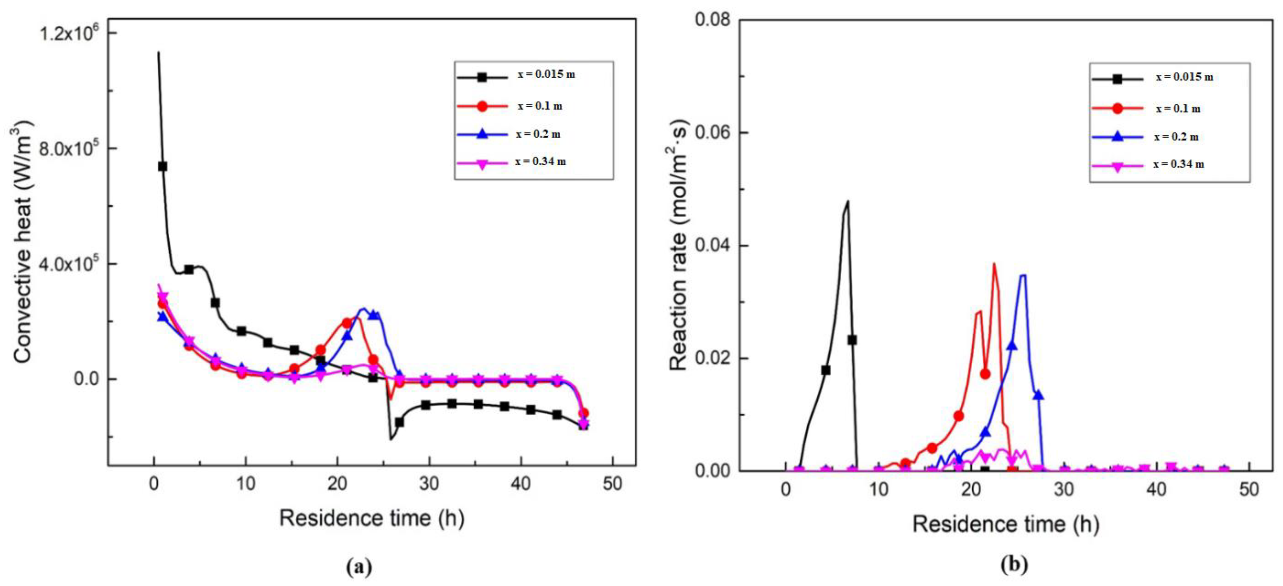
3.3. Heat and Mass Transfer Analysis inside ASK

The numerical simulation of ASK is essentially a study of the heat and mass transfer between limestone and gas, so analysing the heat and mass transfer inside the kiln allows for a better analysis of the ASK performance. Figure 9 represents the carbon dioxide mass fraction, chemical reaction rate, convective heat transfer coefficient, internal and external core thermal conductivity and the calcination zone.
The issue of carbon dioxide emissions has been the subject of energy-saving and environmental-protection concepts in lime kilns. Figure 9a represents the mass fraction variation in carbon dioxide, with local peaks in the mass fraction occurring, which are considered areas of intense limestone decomposition. The carbon dioxide inlet mass fraction of 21.78% increases to 29.12% at the outlet. The rate of limestone decomposition depends on the area of the reaction interface and the reaction rate, which is determined by the chemical reaction constant (a function of particle temperature). Figure 9b represents the rate of limestone decomposition reaction: the highest chemical reaction occurs near the side walls and can reach 1.57 mol/m2·s. High reaction rate zones occur on each limestone fall trajectory and only occur at a height of from 4 to 6 m. However, this zone does not occur in the centre, which explains the incomplete decomposition phenomenon.
Figure 9c shows the convective heat transfer coefficient in the chamber: as the convective heat transfer coefficient is a function of velocity, the convective heat transfer coefficient reaches 22 W/(m2·K); where the flow velocity is higher near the side wall, the most intense convective heat transfer occurs near the fuel gas outlet near the side wall; room-temperature limestone entering the kiln is quickly preheated by the high-temperature fuel gas. Figure 9d shows the solid thermal conductivity at the interface between the external core (calcium oxide) and the internal core (calcium carbonate). As the formula for the thermal conductivity is based on the radius, the lower the decomposition rate, the smaller the intersection, and the more heat will be conducted, so the distribution of thermal conductivity is similar to that of the decomposition rate. Figure 9e shows the area in which decomposition occurs. It can be seen that the ASK is not simply divided into the preheating zone, calcination zone and cooling zone; the preheating zone and calcination zone are shorter near the side wall, while the limestone continues to absorb heat after decomposition is completed and only cools down after passing through the combustion chamber, as shown in Figure 10. The limestone at a distance of from 0.1 to 0.2 m from the sidewall basically conforms to the three-stage distribution. However, the limestone in the centre continues to decompose after passing through the combustion chamber. The method of arranging the thermocouples on-site, therefore, cannot be solely based on the three-stage distribution, and the extremely high temperatures near the walls do not reflect the temperature trend across the entire ASK cross-section.

4. Conclusions

This study presents a three-dimensional simulation of a 200 t/d ASK. Based on the data from measured values, the gas outlet temperature, the differential pressure in the stacked bed and the quicklime outlet decomposition rate in the simulation results are within the permissible error range compared to the real situation. In addition, the flow field, the temperature field and decomposition rate field in ASK are analysed and the input parameters are adjusted to summarise the calcination characteristics of this kiln type. The following conclusions are obtained:
① In ASK at 200 t/d, the fuel gas flows from the combustion chamber through the stacked bed to the induced draft fan, with a pressure drop of approximately 5030.7 Pa. The sidewall effect is more severe, with the gas flow rate near the sidewall being approximately four times that of the central area.
② From the temperature field in ASK, it is difficult for the high-temperature area near the combustion chamber to reach the central area due to insufficient heat, and the side wall effect has a greater impact on all temperature fields in the kiln.
③ Under this condition, there will be 4–5 layers of incompletely decomposed limestone at the quicklime outlet cross-section; the area in which limestone decomposition behaviour occurs in large quantities is in the 6.1–7.4 m region.
④ Under these conditions, the highest chemical reaction in the kiln occurs near the side wall, reaching 1.57 mol/m2·s. the largest convective heat transfer coefficient also occurs near the side wall, reaching 22 W/(m2·K).
In this paper, a complete mathematical model of the coupling of gassolid heat transfer and decomposition reactions is established. Lime kilns are large pieces of equipment for industrial production, with a high energy consumption and high throughput; therefore, the aim of this paper was to investigate the complex heat and mass transfer processes in ASK and to analyse the influence of various operating conditions and structural parameters on the calcination results to provide a theoretical basis for practical production.

Author Contributions

S.D., writing—original draft, mathematical model establishing, programming; B.L., conceptualization, methodology, writing—review and editing; W.R., data curation, field measurements. All authors have read and agreed to the published version of the manuscript.

Funding

This work was supported by the National Natural Science Foundation of China (Grant No. 51934002).

Acknowledgments

I would first like to thank Chief Mu of Dalian Huarui Heavy Industry Group Co., who guided this project throughout, enabling the study to combine theoretical research and practical production, for his invaluable support. Wenjie Rong and Zhengzhe Fang provided a lot of guidance and assistance in the mathematical modelling and data analysis to enrich the study. Finally, I would like to thank my supervisor and corresponding author, Baokuan Li, who has paid great attention to this research from the beginning to end and imparted his profound insights into mathematical modelling to me, as well as meticulous guidance in the conception and writing of the paper, which ultimately led to the completion of this paper.

Conflicts of Interest

The authors declare that they have no conflict of interest.

Nomenclature

ρ g Fluid density; D p Diameter of the particles; α Permeability in porous media; C2 Inertial drag coefficient; M CaCO 3 Relative molecular mass of calcium carbonate; d CaCO 3 Diameter of the internal core calcium carbonate; ρ CaCO 3 density of the calcium carbonate; R D Limestone decomposition rate; k D Reaction constants; p eq Equilibrium partial pressure of carbon dioxide at the front of the reaction zone; p co 2 CO2 partial pressure in the environment; T p Average particle temperature; T i Temperature of internal core calcium carbonate; Y T . C Reaction rate correction factor; λ 1 Thermal conductivity of internal core calcium carbonate, λ 2 Thermal conductivity of external core calcium oxide, r c 1 Calcium carbonate radius’ r c 1 . m 1/2 calcium carbonate radius’ r c 2 . m calcium carbonate radius plus 1/2 calcium oxide layer radius; φ CaCO 3 Volume fraction of calcium carbonate, ρ i density of calcium carbonate, c i specific heat capacity of calcium carbonate; Q D Particle reaction rate; Δ H R Heat of decomposition of calcium carbonate(183,000 J/mol); V p Volume of individual particle; φ CaO Volume fraction of calcium oxide, ρ o density of calcium oxide, c o specific heat capacity of calcium oxide; a v Specific surface area of limestone; h v heat transfer coefficient of gas solid two phase flow; σ Stephen Boltzmann’s constant; 5.6697   ×   10 8   W / ( K 4 · m 2 ) ; β Radiation attenuation coefficient of porous media; N u Nussel number, l z Stacked bed feature length, P r Prandtl number, R e Reynolds number, a Thermal diffusion coefficient; ν Kinematic viscosity of gas, μ dynamic viscosity of gas, u Velocity of gas movement.

References

  1. Song, Y.; Zhang, X. The production and application of active lime in metallurgy. J. Hebei Inst. Technol. 2006, 28, 5–11. [Google Scholar]
  2. Guo, S. Application of active lime in metallurgy. Refract. Lime 2007, 5, 4–5. [Google Scholar]
  3. Oates, T. Lime and limestone. In Kirk-Othmer Encyclopedia of Chemical Technology; Wiley-VCH: Weinheim, Germany, 2010. [Google Scholar]
  4. Szekely, J.; Evans, J.W.; Sohn, H.Y. Gas-Solid-Reactions; Academic Press: New York, NY, USA, 1976. [Google Scholar]
  5. Hills, A.W.D. The mechanism of the thermal decomposition of calcium carbonate. Chem. Eng. Sci. 1986, 23, 297–320. [Google Scholar] [CrossRef]
  6. Escardino, A.; García-Ten, J.; Feliu, C. Kinetic study of the thermal decomposition process of calcite particles in air and CO2 atmosphere. J. Ind. Eng. Chem. 2013, 19, 886–897. [Google Scholar] [CrossRef] [Green Version]
  7. Khinast, J.; Krammer, G.F.; Brunner, C. Decomposition of limestone: The influence of CO2 and particle size on the reaction rate. Chem. Eng. Sci. 1995, 51, 623–634. [Google Scholar] [CrossRef]
  8. Shangqing, L.; Sufang, W.U. Advances in calcium carbonate thermal decomposition. CIESC J. 2015, 66, 2895–2902. [Google Scholar]
  9. Chen, H.; Chen, J.; Wei, R.; Suo, X. Study of the decomposition characteristics of limestone and the law governing the migration of the microscopic structure. J. Eng. Therm. Energy Power. 2013, 1, 73–77, 112. [Google Scholar]
  10. Feng, Y.; Chen, Y. Development of research on calcium carbonate for decomposed kinetics. Bull. Chin. Ceram. Soc. 2006, 3, 140–145, 154. [Google Scholar]
  11. Senegačnik, A.; Oman, J.; Širok, B. Analysis of calcination parameters and the temperature profile in an annular shaft kiln. Part 1: Theoretical survey. Appl. Therm. Eng. 2007, 27, 1467–1472. [Google Scholar] [CrossRef]
  12. Senegačnik, A.; Oman, J.; Širok, B. Analysis of calcination parameters and the temperature profile in an annular shaft kiln. Part 2: Results of tests. Appl. Therm. Eng. 2007, 27, 1473–1482. [Google Scholar] [CrossRef]
  13. Li, J.; Niu, H. Optimization design measures of the structure and performance of the lime kiln. Constr. Des. Project. 2014, 2, 37–40. [Google Scholar]
  14. Senegačnik, A.; Oman, J.; Širok, B. Annual shaft kiln for lime burning with kiln gas recirculation. Appl. Therm. Eng. 2008, 28, 785–792. [Google Scholar] [CrossRef]
  15. Sagastume, A.; Vandecasteele, C. Exergy-based indicators to evaluate the possibilities to reduce fuel consumption in lime production. Energy 2011, 36, 2820–2827. [Google Scholar]
  16. Sagastume, A.; Cogollos, J.B.; Vandecasteele, C. Energy and exergy assessments of a lime shaft kiln. Appl. Therm. Eng. 2013, 51, 273–280. [Google Scholar] [CrossRef]
  17. Cheng, C.; Specht, E. Reaction rate coefficients in decomposition of lumpy limestone of different origin. Thermochim. Acta 2006, 449, 8–15. [Google Scholar] [CrossRef]
  18. Duc, H.; Specht, E. Determination of reaction coefficient, thermal conductivity and pore diffusivity in decomposition of limestone of different origin. In Proceedings of the World Congress on Engineering and Computer Science, San Francisco, CA, USA, 19–21 October 2011; Volume 11, pp. 978–984. [Google Scholar]
  19. Bluhm-Drenhaus, T.; Simsek, E.; Wirtz, S. A couple fluid dynamic-discrete element simulation of heat and mass transfer in a lime shaft kiln. Chem. Eng. Sci. 2010, 65, 2821–2834. [Google Scholar] [CrossRef]
  20. Krause, B.; Liedmann, B.; Wiese, J. Coupled three dimensional DEM-CFD simulation of a lime shaft kiln Calcination, particle movement and gas phase flow field. Chem. Eng. Sci. 2015, 134, 834–849. [Google Scholar] [CrossRef]
  21. Ning, J.; Zhong, B.; Fu, W. Study on the calcination of fine limestone powder at high temperature. J. Combust. Sci. Technol. 2003, 3, 205–208. [Google Scholar]
  22. Mikulčić, H.; Vujanović, M.; Fidaros, D.K. The application of CFD modelling to support the reduction of CO2 emissions in cement industry. Energy 2012, 45, 464–473. [Google Scholar] [CrossRef] [Green Version]
  23. Long, H.; Xu, M.; Yu, D.; Ding, Y.; Wang, K. Two-temperature model of water gas shift reaction in porous media based on fuel NT. Comput. Appl. Chem. 2012, 8, 981–985. [Google Scholar]
  24. Bu, S.; Yang, J.; Li, S.; Wang, Q. Effects of point contact treatment methods on flow and heat transfer of structured packed beds. J. Eng. Thermophys. 2013, 3, 534–537. [Google Scholar]
  25. Liu, G.; Cui, G.; Ma, S.; Han, N. Simulation of the temperature field in a lime kiln by using a local non-heat-equilibrium model and its optimized analysis. J. Eng. Therm. Energy Power. 2018, 2, 96–105. [Google Scholar]
  26. Zhongda, T.; Shujiang, L.; Yanhong, W.; Xiangdong, W. SVM predictive control for calcination zone temperature in lime rotary kiln with improved PSO algorithm. Trans. Inst. Meas. Control. 2018, 40, 3134–3146. [Google Scholar] [CrossRef]
  27. González Suárez, V.M.; García-Gonzalo, E.; Mayo Bayón, R.; García Nieto, P.J.; Álvarez Antón, J.C. Predictive model of gas consumption and air emissions of a lime kiln in a kraft process using the ABC/MARS-based technique. Int. J. Adv. Manuf. Technol. 2018, 100, 1549–1562. [Google Scholar] [CrossRef]
  28. Metz, J.C.; Maciel, E.F.; Garbin, M.; Modolo, R.C.E.; Moraes, C.A.M.; Gomes, L.B.; Brehm, F.A. Infuelnce of electric arc furnace dust and lime kiln waste in portland cement hydration. Ambiente Construído 2020, 20, 225–241. [Google Scholar] [CrossRef]
  29. Juneja, P.K.; Sunori, S.K.; Sharma, A.; Sharma, A.; Joshi, V. Modeling, control and instrumentation of lime kiln process: A review. In Proceedings of the 2020 International Conference on Advances in Computing, Communication & Materials, Dehradun, India, 21–22 August 2020. [Google Scholar]
  30. Yur’ev, B.; Dudko, V. Determination of key parameters required to optimize calcination process in ferrous metallurgy heating plants. Solid State Phenom. 2021, 316, 282–287. [Google Scholar] [CrossRef]
  31. Yang, Y.; Wang, L.; Xia, D.; Jiang, Z.; Jiang, B.; Zhang, P. Novel lime calcination system for CO2 capture and its thermal-mass balance analysis. ACS Omega 2020, 5, 27413–27424. [Google Scholar] [CrossRef]
  32. Zhaohua, L. Calculation of effective thermal conductivity of foam porous media. J. Nanjing Univ. Sci. Technol. 2001, 3, 257–261. [Google Scholar]
  33. Lingli, Z.; Jie, B.; Bin, Q. Calculation of convective heat transfer for active limes pre-heater. Metall. Equip. 2012, 6, 6–8. [Google Scholar]
Figure 1. Structural sketch of the ASK and combustion chamber.
Processes 10 00648 g001
Figure 2. Flow field and calcination area calculation domain: (a) flow field calculation domain; (b) calcination area calculation domain.
Processes 10 00648 g002
Figure 3. Gas velocity distribution and partial enlargement.
Processes 10 00648 g003
Figure 4. Gas and solid temperature distribution and partial enlargement.
Processes 10 00648 g004
Figure 5. Distribution of gas and solid temperature at different distances: (a) distribution of gas temperature; (b) distribution of solid temperature.
Processes 10 00648 g005
Figure 6. Decomposition degree distribution and partial enlargement in the kiln: (a) plane1 (b) plane2 (c) partial enlargement.
Processes 10 00648 g006
Figure 7. Distribution of decomposition degree at different distances: (a) y = 0.1 m; (b) y = 6.1 m; (c) y = 7.4 m; (d) y = 9 m; (e) distribution of decomposition degree.
Processes 10 00648 g007
Figure 8. Temperature and decomposition at various locations in chamber during its descent: (a) x = 0.015 m; (b) x = 0.1 m; (c) x = 0.2 m; (d) x = 0.34 m.
Processes 10 00648 g008
Figure 9. Distribution of heat and mass transfer in chamber: (a) CO2 mass fraction; (b) chemical reaction rate; (c) convective heat transfer coefficient; (d) internal and external core thermal conductivity; (e) calcination zone.
Processes 10 00648 g009
Figure 10. Convective heat transfer and chemical reaction rate distribution: (a) convective heat transfer; (b) chemical reaction rate.
Processes 10 00648 g010
Table 1. Structural size and particle properties.
Structure NumericalValueParticulate MaterialityValue
Height of flow field, m22CaO density, kg·m−33310
Height of calcination zone, m13.7CaCO3 density, kg·m−32810
ASK inner ring, m7.24 CaO   thermal   conductivity ,   W / ( m · K )0.07
ASK outer ring, m9.08 CaCO 3   thermal   conductivity ,   W / ( m · K )2.26
Pairs of fuel gas inlet spacing, m0.68 CaCO 3   decomposition   temperature ,   K 1073
Lower fuel gas inlet height, m6.47
Upper fuel gas inlet height, m6.958
Table 2. Material specific heat capacity.
Material NameValue
O2 2.278   ×   10 10   T 4 + 3.414   ×   10 6   T 3     0.00015   T 2 + 0.293   T + 834.827
N2 7.256   ×   10 10   T 4 + 1.674   ×   10 6   T 3     0.0011   T 2 + 0.418   T + 979.043
CO2 4.000   ×   10 10   T 4 + 1.297   ×   10 6   T 3     0.002   T 2 + 1.874   T + 429.929
Vapor 1.157   ×   10 9   T 4 + 3.216   ×   10 6   T 3     0.0029   T 2 + 1.604   T + 1563.077
CaO 9   ×   10 7   T 3     0.0024   T 2 + 2.4372   T + 304.46
CaCO3 6   ×   10 7   T 3     0.0016   T 2 + 1.5455   T + 422.74
Table 3. Fuel gas composition.
fuel gas compositionH2ON2CO2O2
Volume fraction%1.0271.8915.1211.97
Publisher’s Note: MDPI stays neutral with regard to jurisdictional claims in published maps and institutional affiliations.

