Abstract
In conjunction with the increasing demand for material cutting, such as the decommissioning and dismantling of nuclear facilities, advanced cutting technologies need be developed to increase precision and cost-effectiveness. As compared with other cutting technologies, laser cutting offers advantages of greater cutting precision, accuracy, and customization. In this work, we investigated the constitution, classification, and current status of this technology. Pollutant emission during laser cutting, corresponding pollution control methods and apparatus were proposed as well. Laser cutting equipment mainly comprises an automated system integrating a fiber laser, industrial computer, servo motor control, electrical control, and detection technology. It mainly consists of mechanical and electrical control parts. Laser cutting equipment is distinguished by light source, power, and cutting dimensions. Known variants of laser cutting technology involve vaporization, fusion, reactive fusion, and controlled fracture cutting. During the cutting process, dust, smoke, and aerosols can be released, which is an environmental concern and poses a threat to public health. The selection of the dedusting method and design of apparatus should take into account the dust removal rate, initial capital cost, maintenance cost, etc. Multi-stage filtration such as bag filtration combined with activated carbon filtration or electrostatic filtration is accepted.
1. Introduction
Cutting is a process in which the operators move a material such as metal and the tool concurrently in order to shape the workpiece into a desired form. Along with the increasing demand for different material cutting, advanced cutting technologies are being developed to increase precision and cost-effectiveness. The most common methods include laser cutting, plasma cutting, water jet cutting, and oxy-fuel cutting [1,2,3]. Among them, plasma cutting is conducted by means of a concentrated plasma arc [4,5,6,7]. This approach was developed from plasma welding in the 1960s and emerged as a productive method of cutting sheet and plate metal in the 1980s. Its characteristics include high speed and low cost; however, it produces high UV radiation and generates excess fumes. It is also noisy and cannot offer precise cuts. Water jet cutting uses high pressure jets of water provided by pressurizing pumps to cut and shape materials [8,9,10,11,12]. It is capable of cutting almost any material relatively cheaply, without altering its properties. In addition, it does not produce any dust, fumes, or airborne particles and operates without chemicals [13]. Disadvantages include longer cutting time, higher initial cost, and water mist created. Oxy-fuel technology is a thermal cutting process using oxygen and fuel gas to cut through materials [14,15,16,17]. It is reliable, accurate, and can cut objects with metallurgically optimal surfaces (oxidized). However, it cannot cut stainless steel under normal circumstances, and the cut speed is slow as compared with that of plasma cutting [7]. The choice of cutting technologies significantly affects quality, mechanical properties, and microstructure of the metals. The question is: Which is the best cutting technique?
Laser technology appeared in the 20th Century and integrates optics, electromechanical, software, and material technologies. It has been widely applied in the heavy metals, electronic, light, military, and medical industries as well as other fields [18]. Laser cutting was introduced as an industrial technology more than two decades ago and is based on absorption of laser light in the material surface leading to partial liquification and evaporation of the material in a narrow kerf. In order to remove molten material from the interaction zone, an assist gas is used, and relative movement between laser beam and workpiece leads to cutting kerf formation. As compared with other cutting technologies, laser cutting offers advantages of greater cutting precision, accuracy, and customization [19,20,21,22,23]. It has been extensively applied in the cutting of various materials, such as steel and aluminum sheets as well as three-dimensional bodies. However, there are different laser cutting technologies, such as vaporization, melting, oxidation, and control fracture. Each one has different properties that make it ideal for different purposes. In addition, during the cutting of metals, especially radioactive metals, metal vapor and melt are generated, which is an environmental concern and poses a threat to the health of workers. As compared with other energy sources, nuclear energy offers advantages of low cost operation, low carbon emission, and reliability, and has been recognized as one of the most environmentally friendly resources [24,25,26,27,28,29,30]. The average share of nuclear power in global electricity generation has stagnated at 10.5% since 2013. There will be considerable room to grow in the context of carbon neutrality, and nuclear power is expected to account for approximately 10% of energy sources in China by 2030 and 19% by 2060. France, Finland, Poland, and other countries have planned to build new reactors or have considered extending the maximum service period of old reactors. However, in conjunction with the rapid development of nuclear energy, an upcoming wave of decommissioning and dismantling of nuclear facilities will be faced. Many radioactive components of a nuclear reactor and devices need be cut and then treated properly. To the best of our knowledge, there are sparse comprehensive studies on laser beam cutting and corresponding pollution control strategy. Therefore, in this work, the constitution, classification, and current status of laser cutting technologies are analyzed. On this basis, pollutant emission during laser cutting, corresponding pollution control methods, and apparatus are proposed.
2. Laser Cutting
2.1. Constitution
Laser cutting equipment comprises an automated system integrating industrial computer, servo motion control, electrical control, and detection technology. It mainly consists of mechanical and electrical control parts [31,32,33]. Between them, the mechanical parts mainly include a processing platform, marble platform, pneumatic structure, equipment overall frame, and fiber laser. The electrical control parts consist of an industrial computer operation interface, servo motor control, electrical control, detection sensor, CCD image processing system, etc. The equipment incorporates a fully enclosed safety design. During operation, the processing status of the equipment can be observed from the front sliding door safety window, ensuring safety for the operator. A sensor is installed at each detachable door panel of the equipment. When any sensor contact is not sensed during the laser emission process, the equipment sounds an alarm, and the laser emission is interrupted.
2.1.1. Laser
Lasers are grouped into solid-state, gas, liquid, and semiconductor lasers [34,35]. Among them, the solid-state laser has the advantages of short wavelength, light concentration, and good stability. It is suitable for precision machining, especially hole machining under pulse conditions. However, it is mainly used for punching, spot welding, and thin plate cutting due to its low energy efficiency. As a comparison, the gas lasers, especially CO2 gas lasers, can reach a power of 45 kW in continuous mode and 5 kW in pulsed mode, so they are most widely used in machinery manufacturing and processing industries. The laser sources of laser-based cutting equipment mainly include CO2, fiber, and YAG lasers [36,37,38,39].
CO2 Laser
The laser medium of a CO2 laser is CO2 mixed gas, operating primarily in the mid-infrared spectral region (3–30 µm) at a wavelength of 10.6 μm [40,41,42,43]. Its laser conversion efficiency is relatively high, and the heat generated by the laser can be quickly transferred outside the laser gain region through convection or radiation [44]. Therefore, the average laser output power can reach a very high level (above 10 kW) to meet the requirements of high-power laser processing. CO2 lasers can be divided into low-, medium-, and high-power CO2 lasers according to their output power. The CO2 laser cutting machine can cut carbon steel to within 20 mm, stainless steel to within 10 mm, and aluminum alloy to within 8 mm. It can also cut high-quality non-metallic materials such as wood, acrylic, PP, and polymethyl methacrylate (PMMA) to within 60 mm. The CO2 laser cutting machine is equipped with nozzles for blowing oxygen and compressed air or inert gas N2 as assist gas at the exit beam to improve the cutting speed and the smoothness of the cut. In order to improve the stability and lifespan of the power supply, the discharge stability of the high-power laser must be addressed for the CO2 gas laser. Traditional high-power axial fast-flow CO2 lasers are still the mainstream configuration of high-power laser cutting equipment. Although fiber lasers have developed rapidly in recent years, CO2 lasers still occupy a majority share of up to 65%. The high-power CO2 lasers used for laser processing are mainly cross-flow, axial, and swirl lasers. Fomin et al. [40] used CO2 lasers with oxygen as an assist gas to cut low-carbon steel sheets, and the minimum roughness was ensured at a certain value of energy per unit volume of the melt. Chen et al. [45] analyzed the effects of different parameters on the surface roughness of PMMA microchannels with the CO2 laser LCJG-1290 cutting process. The optimal conditions were determined as a laser power of 9 W and laser scanning speed of 600 mm/min to reach the arithmetical mean roughness of 110 nm. Parthiban et al. [46] investigated the optimal parameters of CO2 laser cutting parameters on an austenitic type stainless steel sheet. The minimum of kerf width for a straight profile and kerf width for a curved profile were obtained as 0.3281 and 0.3120 mm with laser power, cutting speed, and gas pressure of 2807.45 W, 5500 mm/min, and 0.9 MPa. Russo Spena [47] investigated the effects of CO2 laser cutting on surface quality of 22MnB5 hot stamping boron steel sheets. A laser power of 173 W, cutting speed of 2040 mm/min, and assist gas pressure of 0.4 MPa were the optimal combination with a desirability of over 90%.
Fiber Laser
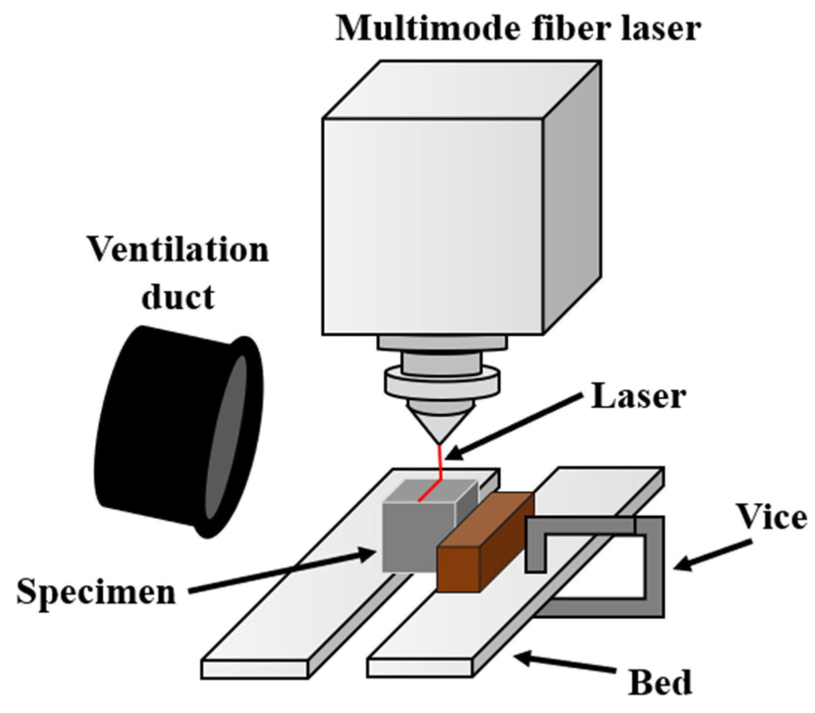
The advantages of fiber lasers mainly include their: (1) waveguide structure, which has the characteristics of high gain, high conversion efficiency, low threshold, good output beam quality, narrow line width, simple structure, and high reliability; (2) easily achieved coupling with optical fibers, and output peak power can be as high as hundreds of kilowatts; (3) high absorption efficiency for most materials, small size, light weight, and transportability; (4) very precise cutting due to the small diameter of the focused spot (10–100 μm), which can eliminate some post-processing steps; (5) easy cooperation with the manipulator through the optical fiber output to achieve laser long-distance processing. The overall photoelectric conversion efficiency is as high as 25–30%; (6) long-term stability, easy maintenance, and low operating cost [48,49,50]. A fiber laser cutting machine is shown in Figure 1. Although fiber laser cutting capable of cutting most materials, it is not suitable for cutting acrylic or polycarbonate materials. Tamura et al. [51] revealed that laser cutting of steel components up to 300 mm in thickness using a 30 kW fiber laser was successful. Laser cutting is a promising technology in nuclear decommissioning.

Figure 1.
Scheme of fiber laser cutting machine [52].
YAG Laser
The output wavelength of Nd/YAG is 1.06 μm, which is exactly an order of magnitude smaller than that of the CO2 laser [53,54]. Traditional solid-state lasers are usually pumped by high-power gas discharge lamps with a pumping efficiency of 1–3%. The large amount of energy emitted from the pump lamp is converted into heat energy, which not only causes the laser to adopt a bulky cooling system but also produce the inevitable thermal lens effect of the working material to deteriorate the beam quality [55]. In addition, the life span of the pump lamp is about 300 h. Thus, operators must frequently change the lamp and interrupt the system work, which is a time-consuming process that reduces the cutting efficiency.
The YAG solid-state laser cutting machine is low-cost and high-stability, but its energy efficiency is generally less than 3%, and the output power of current products is mostly below 600 W. Due to the low output energy, it is mostly used for cutting below 8 mm. The YAG solid-state laser cutting machine is used in medium-sized enterprises and is most often used in sheet metal manufacturing, home appliance manufacturing, kitchenware manufacturing, decoration and decoration, advertising, and other industries. It has gradually replaced traditional processing equipment such as wire cutting, CNC punching, water cutting, and low-power plasma. In addition, its green laser beam can be applied under pulse or continuous wave conditions, which has the advantages of short wavelength and good light concentration. Therefore, the YAG solid-state laser cutting machine is not only suitable for precision machining, especially hole machining under pulse conditions, but is also for cutting, welding, lithography, etc. Its wavelength is not easily absorbed by non-metal, so it is not suitable for cutting non-metal materials. In addition, the YAG solid-state laser cutting machine requires improved stability and lifespan of the power supply to develop a large-capacity, long-life optical pump excitation light source that can greatly improve the energy efficiency [56]. Sharma and Yadava [53] conducted experimental analysis of Nd/YAG laser cutting of sheet materials. The surface roughness is significantly affected by cutting speed, and the use of inert gases shows better surface quality though it has relatively high cost. Tamilarasan and Rajamani [57] proposed a multi-response optimization approach for the Nd/YAG laser cutting parameters of a titanium superalloy sheet. The optimal parameter settings were determined as a pulse width of 1.89 ms, pulse energy of 4.40 J, cutting speed of 10.16 mm/min, and gas pressure of 0.798 MPa. Leone et al. [58] studied the Nd/YAG laser cutting of Al alloy 6061-T6 sheets. The laser could be used to cut 1 mm-thick AA6061-T6 sheets with a cutting speed up to 700 mm/min, obtaining narrow kerfs (<200 μm), a fine taper angle (<4°), and a low dross height (about 40 μm). Mishra et al. [59] investigated the various parameters of laser cutting on a hybrid composite laminate of carbon–basalt–Kevlar. The optimal parameters were a lamp current of 200 A, pulse width of 2.5 ms, stand-off distance of 2 mm, gas pressure of 1.2 MPa, and cutting speed of 200 mm/min.
2.1.2. Focusing System
In laser cutting processes, the function of the focusing system is the lossless delivery of a laser beam to the machining point without affecting beam quality and the focusing of the laser beam onto the workpiece achieving the required power density [60,61,62]. The focusing system consists of a feeding fiber, fiber outcoupling optics, collimator, focusing optic, and protection window. Among them, the feed fiber routes the laser radiation from the laser source to the focusing system. In fiber outcoupling optics, the end of the fiber is connected to a cylindrical extraction block made of fused silica. The collimation devices are used to collimate a laser beam generated by the emission apparatus, focusing devices to focus the collimated laser beam, leaving the collimation devices and a casing to house and contain the focusing unit. A doublet lens is typically used here, as well as singlets or aspheric lenses. The protection window is designed to protect the focusing optic against contamination from the cutting process and seclude the process gas volume [63].
2.1.3. Electrical System
The electrical system includes the laser power supply and control system. Its function is to supply laser energy and control the output mode [64,65]. In addition, the movement of the workpiece or the laser beam is related to factors such as pressure and flow. Its degree of influence is roughly similar to that on the diameter of the hole [66].
2.2. Classification of Cutting Mechanisms
Laser cutting equipment is distinguished by light source, power, and cutting dimensions. The technical indicators can be specifically divided into cutting speed, cutting accuracy, driving mode of the motion mechanism, manual or auto focus function, and table size. Known variants of laser cutting technology involve vaporization, fusion, and reactive melting cutting (Figure 2). In general, during the laser beam cutting process, the material is ejected in the molten stage, and a small fraction is removed as vapor. However, there are different mechanisms of laser cutting of sheet material for these methods.
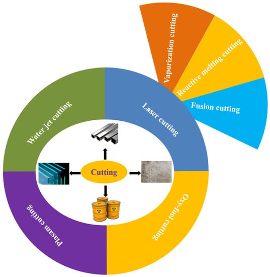
Figure 2.
Laser cutting technologies.
2.2.1. Vaporization Cutting
Vaporization cutting is the most widely used form of cutting due to its high laser power density, which allows the surface of the workpiece to quickly reach the boiling point (Table 1). Once the laser is irradiated on the mechanical workpiece, it is effectively absorbed and converted into heat energy. Then, the heat energy allows the workpiece surface to quickly reach the boiling temperature and form a key chain on its surface. In addition, under the action of surface oxidation, the absorption rate is greatly improved, and the ejected steam effectively blows away a large amount of molten material, promoting the material to vaporize into a notch [67,68,69]. Aden et al. [70] investigated the vaporization process for steel and aluminum using theoretical methods. To avoid the occurrence of laser beam–vapor interaction via bremsstrahlung, a Nd/YAG technique was chosen for the experimental investigation. The laser vaporization cutting is often used to cut very thin metal and non-metallic materials. In addition, it may disrupt melt flow and cause discontinuous streak formation [71].

Table 1.
Advantages and disadvantages of different cutting methods.
2.2.2. Fusion Cutting
Fusion cutting requires a laser power that it is able to cut and process on the surface of the workpiece to form a key chain. In contrast to vaporization cutting, the melt under fusion cutting conditions needs to be effectively purged with assist gas instead of being removed by the gasification process [72,73,74]. Fusion cutting avoids the problem of emission and absorption of laser beam by steam. When the laser beam moves in the notch gap, it only interacts with the front material. In addition, the shooting angle is too large when the laser beam is projected onto the material surface of the workpiece, and as a result the actual absorbed laser energy cannot continue to melt. Therefore, the fusion process needs to be carried out step by step. The laser power used in fusion cutting is far less than that of vaporization cutting. It is mainly used in materials that can react exothermically with oxygen, such as common aluminum and copper. The assist gases used include various inert gases and inactive gases. Laser fusion cutting has the advantages of producing a virtually oxide-free cutting edge (Table 1). It is used when workpieces must fulfill high visual requirements without further processing. However, when the melt is ejected from the cut kerf by an assist gas, a fraction may adhere to the lower cut edge and form a burr. Adjusting the process parameters to minimize burr formation is a challenging task that becomes more and more difficult as sheet thickness increases. Stoyanov et al. [75] studied the dynamics of the melt during its ejection from the kerf. A melt ejection forming a compact and stable threefold outflow is a characteristic property of a burr-free cut.
2.2.3. Reactive Melting Cutting
The essence of reactive melting cutting is to effectively heat the workpiece to the ignition point by using a laser beam then produce an exothermic reaction based on industrial pure oxygen [76,77,78]. A considerable amount of heat is released during this process. The material at the notch is oxidized and burnt to form molten oxide, which is blown away to form the notch. At the same time, the heat released can also be supplied to adjacent materials to reach the ignition point. It can thus ensure continuous reaction melting and cutting. The laser power required for reactive melting cutting is less than 1/20 of that of vaporization cutting. It is widely used in cutting steel and titanium materials by machinery manufacturing enterprises. However, the large amount of exothermic energy released by the oxidation of the material destabilizes the melt front, and the highly oxidized cut edge produces a relatively large kerf width [79].
3. Pollution Control Strategy
3.1. Pollution Generation
In recent years, laser cutting has been widely used in the field of sheet metal processing. Laser cutting locally heats the material to thousands to tens of thousands of degrees Celsius in a very short time, which is achieved by scanning the workpiece surface with a high-power density laser beam. In addition, laser cutting makes the irradiated material quickly melt, vaporize, ablate, or reach the ignition point and at the same time blows away the molten material with the help of high-speed airflow to achieve the purpose of cutting. During the cutting process, a large amount of dust, smoke, and aerosols are generated, which causes an environmental concern and poses a threat to the health of workers [80,81,82]. The amount of smoke and dust emitted by laser cutting is related to the cutting speed and the setting parameters of the cutting air pressure. If the practitioner uses reasonable settings, the laser cutting fume emission is greatly reduced. In addition, the workpiece material has a significant effect on emissions. Taking the cutting of 6 mm-thick low carbon steel as an example, the amount of smoke and dust emitted per 1 m cut is 440 mg. When cutting 6 mm-thick chromium-nickel material or galvanized steel plate, the smoke and dust emission per 1 m cut is 2000 mg. For the cutting of 6 mm-thick low carbon steel, 39.6 g of smoke and dust can be released per hour with a cutting speed of 1500 mm/min. Generally speaking, the laser cutting machine releases a large amount of smoke and dust. It mainly contains metal oxide particles of metals such as iron oxide and aluminum oxide.
3.1.1. Particle Matter
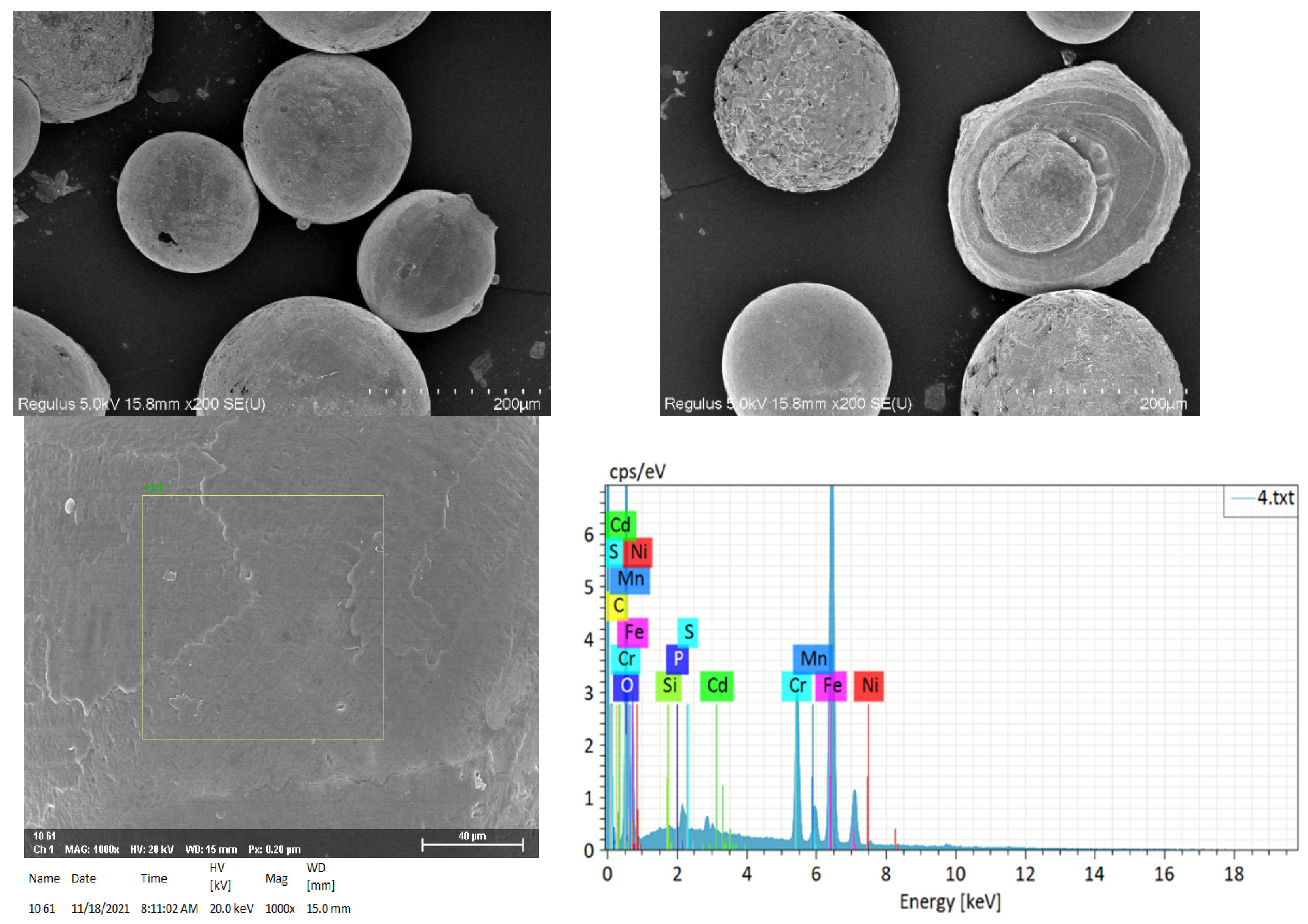
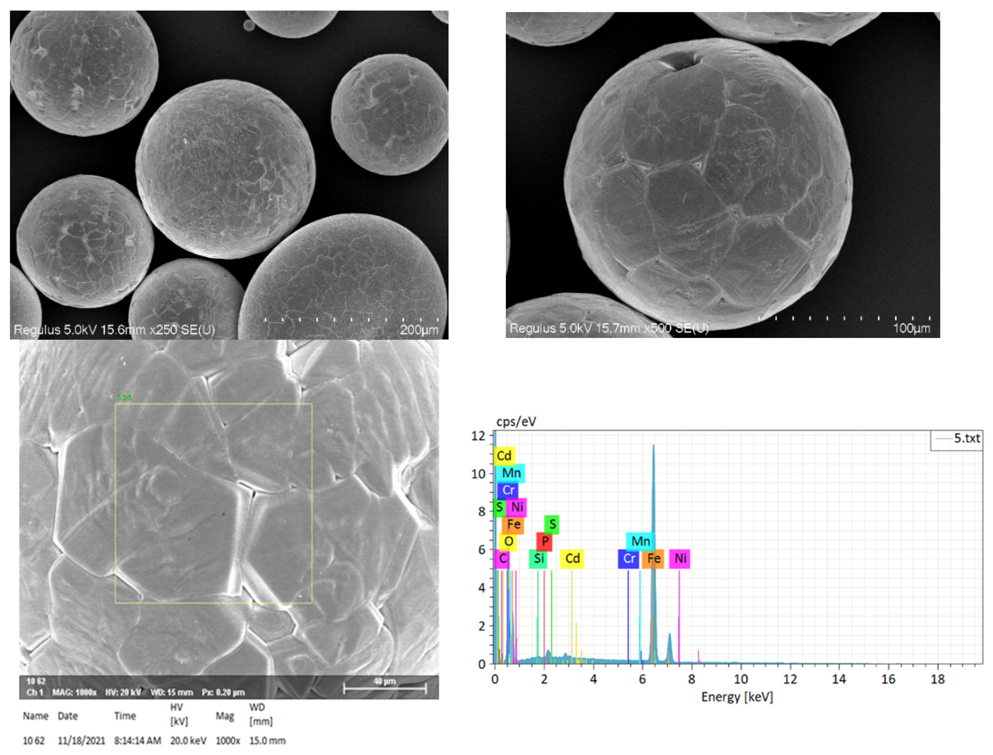
In the process of laser cutting metal materials, the smoke and dust released are divided into two types according to the size of smoke and dust particles, namely dust and aerosols [83,84,85]. The particle size of dust generally exceeds 10 μm and the size of that of an aerosol is less than 10 μm. During deactivation and decommissioning activities, laser cutting is usually used to cut metals, such as spent fuel storage racks and nuclear waste containers. The generated airborne species of matter, called aerosols, may be inhaled if suitable respiratory protection is not used. Inhalation of the airborne metallic aerosols has been reported to cause ill health effects, such as acute respiratory syndrome and chromosome damage in lymphocytes [86]. In the nuclear industry, metals may be contaminated with radioactive materials. Cutting these metals, as in the size reduction of gloveboxes and tanks, produces high concentrations of airborne transuranic particles. Particles of the respirable size range (size < 10 µm) deposit in various compartments of the respiratory tract, the fraction and the site in the respiratory tract depending on the size of the particles. Measuring aerosol size distribution is important for the design of appropriate filtration systems. Size distribution of the aerosols generated during cutting of different metals using a plasma torch has been studied [87]. Particles with mass median aerodynamic diameters of close to 0.2 µm were observed, arising from condensation of vaporized material and subsequent rapid formation of aggregates. Dazon et al. [88] probed the characteristics, chemical composition, and particle size distributions of aerosols released during laser cutting of fuel debris simulants in air and underwater conditions in the context of the dismantling of Fukushima Daiichi. The aerosols systematically have an aerodynamic mass median diameter below 1 μm, with particle sizes generally between 60 and 160 nm for air cutting conditions, and 300 and 400 nm for underwater experiments. Iron, chromium, and nickel were found in more than 50% in the samples. Peillon et al. [89] studied the aerosol particle emissions of a Nd/YAG laser cutting technique used for the decommissioning of nuclear facilities. It was found that the mass of aerosol per unit area of laser cutting decreased when the laser power and cutting speed increased. When cuts were carried out underwater, the production of aerosol particles mass per unit area of cut was reduced by a factor of 10 and was below 70 g·m−2. Dodds and Rawcliffe [90] investigated the radionuclide distribution during ytterbium doped fiber laser cutting of contaminated stainless steel. Cs-133 has been measured in samples and swabs taken from throughout the laser cutting facility at decreasing concentrations correlating with the distance from the cut test pieces. We studied the particle matter released during the laser cutting of stainless and carbon steel (Figure 3 and Figure 4). The particulates were collected at the end of a laser cutting machine. From the SEM images, we can observe that these particulates showed a solid sub-spheroidal shape with a rough surface. This was due to the rapid cooling which resulted in the shrinkage. The particle size was approximately 100–200 µm. From the EDX analysis, we can find that the chemical components were in the form of metal oxides. They were iron, chromium, and manganese oxides for particle matter from stainless steel cutting and iron and manganese oxides for matter from carbon steel cutting.

Figure 3.
Particle matter released during the laser cutting of stainless steel.
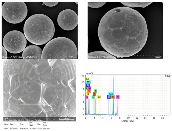
Figure 4.
Particle matter released during the laser cutting of carbon steel.
3.1.2. Volatile Organic Compounds
A laser cutting machine sometimes requires lubricating oil to be sprayed on the working table before cutting to improve its smoothness. The smoke and dust released contain chemical components, such as toluene, acetate, and butanol in this case. In addition, when the work surface of the laser cutting machine is covered with a polyethylene protective film, the smoke and dust contain aliphatic and olefin compounds. The main pollutants created during laser cutting of a laminar composite steel/PUR foam/PS are dust and volatile organic compounds. Qualitative analysis showed acetone and styrene present in exhaust gases. These compounds were probably products of oxidation of polystyrene. Qualitative analysis of gases emitted during cutting showed presence of benzene, butanol, cyclohexane, and vinyl acetate but in trace quantities impossible to be determined [67].
3.2. Pollution Control
There is no filter system or medium that can absorb all the smoke, dust, fumes, gas, or debris generated during the use of lasers. On some occasions with strict limits of pollution emission, multiple treatment systems or hybrid systems with different filtration methods are required to control pollution. Modern dedusting technologies include screen filtration, bag filtration, electrostatic filtration, and activated carbon filtration [91,92,93,94]. Among them, the electrostatic systems have some obvious advantages. First, the filter can be cleaned and does not need be replaced, eliminating the cost of repeated filter replacement. Second, a well-designed system can provide high removal rates of soot and smoke particles at a submicron scale. Another advantage is the very small loss of air flow when dirt builds up on the filter. During laser operating, the air laden with pollutants is first extracted through a pre-filter. Then, it enters a high-density ionization zone filled with smoke and soot particles. The charged particles pass through a collection chamber which is composed of alternating voltage and a grounded plate. They are adsorbed and stay on the oppositely charged collection plate in this process. A cylindrical filter is used to trap particles deposited from the collection plate. As a comparison, the mechanical filtration systems are continuously fed into the air stream during the build-up of contaminants. Therefore, regular maintenance is required in order to maintain a high removal rate. Because these systems use a high-voltage DC photovoltaic system, they are not suitable for highly conductive or flammable pollutants. Such systems are primarily designed to absorb fine particles but cannot remove gases or vapors. Some systems use disposable high-efficiency particle air or high-purity filters to achieve a filtration efficiency of 99.97% for 0.3 μm particles [95]. In some circumstance, the pollutants may contain a small quantity of aerosols and VOCs. Multi-stage filtration can be adopted to remove pollutants and achieve safe and qualified discharge. The particulates are first removed by physical methods, and then other pollutants are removed by activated carbon.
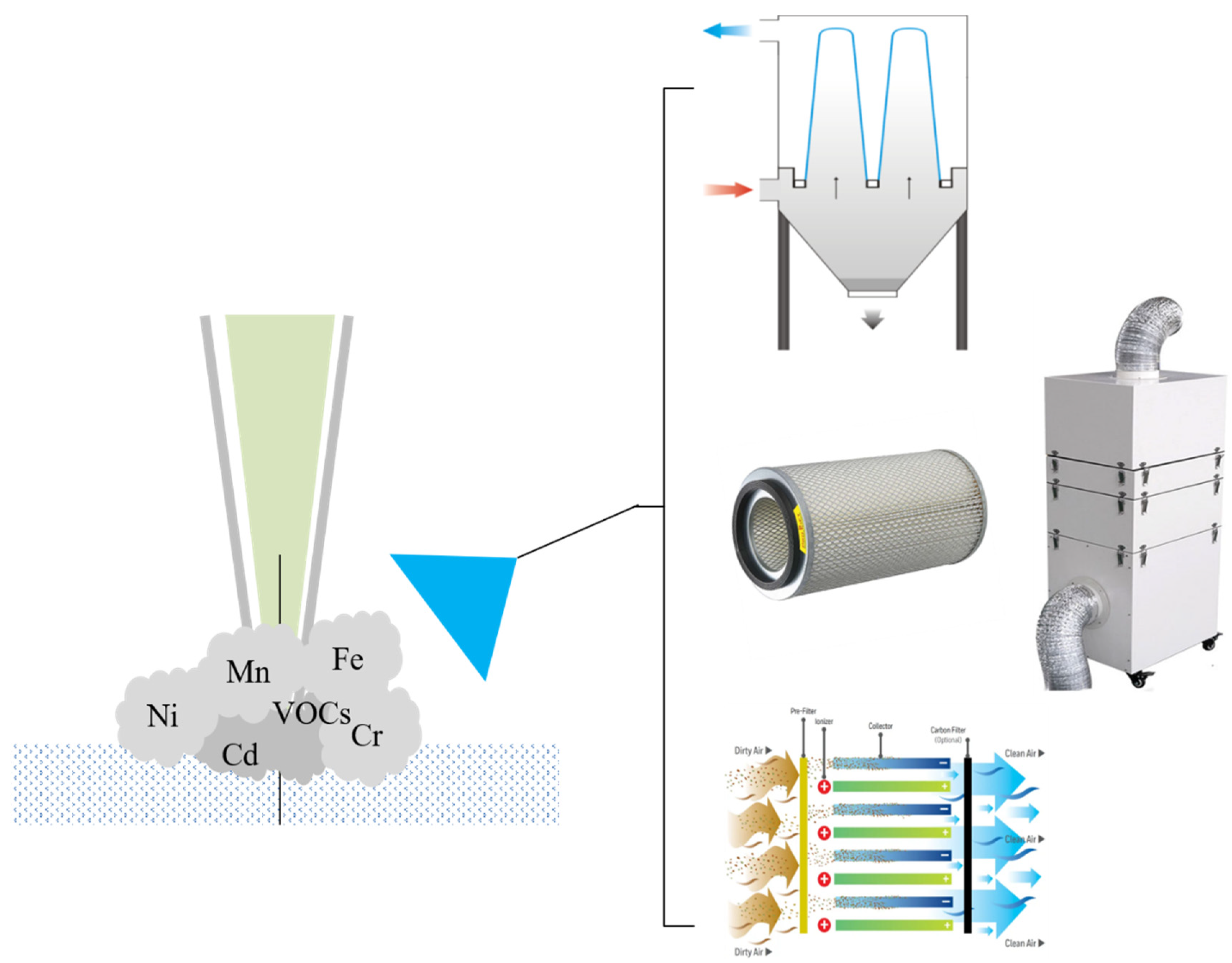
In general, the selection of dedusting method and equipment depends on the characteristics of cutting materials [96]. According to the composition of waste, several steps of dust collection, filtration, detection, and discharge should be performed. The equipment includes draught fans, dust hoods and boxes (including filters and activated carbon), and online gas detectors (Figure 5). The design of each unit may affect the overall removal effect. Zhang [97] designed a set of dust-removing laser cutting machines. The dust box is arranged at the upper end of the second moving frame, while the dust hood is arranged at its lower end. Through such a design, a good vacuuming effect can be maintained according to the movement of the laser cutting mechanism. The dust is sucked into the dust box through the dust hood and the suction pipe under the action of the fan. A filter screen and activated carbon filtration are used, which avoids the accumulation of smoke and dust and pollution in the environment. Powell et al. [98] reviewed the fume filtration in the context of industrial laser cutting. Self-cleaning or surface filtration can be used to good effect when cutting metals.
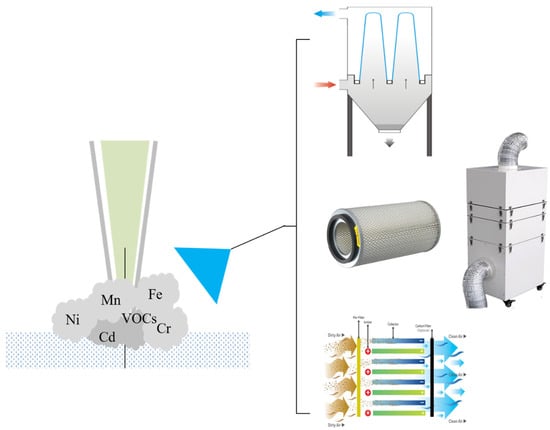
Figure 5.
The pollution control strategy for laser cutting.
4. Conclusions
In conjunction with the rapidly increasing demand for metal cutting, advanced cutting technologies need be developed to increase precision and cost-effectiveness. The most common methods include laser cutting, plasma cutting, water jet cutting, and oxy-fuel cutting. As compared with other technologies, the laser cutting technique has the advantages of greater cutting precision, accuracy, and customization, giving it great potential in the dismantling of nuclear facilities. A laser cutting machine is an automated system comprising an industrial control computer, servo motor control, computer numerical control, and optical sensor. It mainly consists of mechanical and electrical control parts. Laser cutting equipment is distinguished by light source, power, and dimensions. Known variants of the laser cutting technologies involve vaporization, fusion, and reactive melting cutting. During the cutting process, dust, smoke, and aerosols are generated, which is an environmental concern and poses a threat to the health of operators. Modern dedusting technologies include screen filtration, bag filtration, electrostatic filtration, and activated carbon filtration. On some occasions with strict limits of pollution emission, multiple treatment systems or hybrid systems with different filtration methods are required to control pollution. Laser cutting technology is promising, although there are still some challenges in the dedusting process. The design of the dedusting method should take into account the dust removal rate, initial capital cost, maintenance cost, etc. Multi-stage filtration such as bag filtration combined with activated carbon filtration or electrostatic filtration is accepted. It is expected to provide a significant reference for material cutting (especially metal cutting) and its pollution control in practice.
Author Contributions
H.X., Conceptualization, Z.Y., methodology, Y.H.; formal analysis, Y.G.; investigation, Y.L.; resources, Y.H. and B.W.; data curation, X.C. and Y.S.; writing—original draft preparation, Y.H., Z.Y. and B.W.; writing—review and editing, M.J. and J.L.; project administration; Z.Y. and H.X.; funding acquisition. All authors have read and agreed to the published version of the manuscript.
Funding
This work was supported by the Zhejiang Provincial Natural Science Foundation of China (Grant no. LTY21B070002).
Institutional Review Board Statement
Not applicable.
Informed Consent Statement
Not applicable.
Data Availability Statement
Not applicable.
Conflicts of Interest
The authors declare no conflict of interest.
References
- Ardelean, F.A. Study regarding modern cutting technologies. Rev. Tehnol. Neconv. 2011, 15, 11. [Google Scholar]
- Perel, V.; Hloch, S.; Tozan, H.; Yagimli, M.; Hreha, P. Comparative analysis of abrasive waterjet (AWJ) technology with selected unconventional manufacturing processes. Int. J. Phys. Sci. 2011, 6, 587–593. [Google Scholar]
- Lee, G.-R.; Lim, B.-J.; Cho, D.-W.; Park, C.-D. Selection methodology of the optimal cutting technology for dismantling of components in nuclear power plants. Ann. Nucl. Energy 2022, 166, 108808. [Google Scholar] [CrossRef]
- Lazarević, A.; Ćojbašić, Ž.; Lazarević, D. Computationally intelligent modelling of the plasma cutting process. Int. J. Comput. Integ. Manuf. 2020, 33, 252–264. [Google Scholar] [CrossRef]
- Lillemäe-Avi, I.; Liinalampi, S.; Lehtimäki, E.; Remes, H.; Lehto, P.; Romanoff, J.; Ehlers, S.; Niemelä, A. Fatigue strength of high-strength steel after shipyard production process of plasma cutting, grinding, and sandblasting. Weld. World 2018, 62, 1273–1284. [Google Scholar] [CrossRef] [Green Version]
- Gani, A.; Ion, W.; Yang, E. Experimental Investigation of Plasma Cutting Two Separate Thin Steel Sheets Simultaneously and Parameters Optimisation Using Taguchi Approach. J. Manuf. Process. 2021, 64, 1013–1023. [Google Scholar] [CrossRef]
- Devaraj, R.; Nasr, E.A.; Esakki, B.; Kasi, A.; Mohamed, H. Prediction and Analysis of Multi-Response Characteristics on Plasma Arc Cutting of Monel 400™ Alloy Using Mamdani-Fuzzy Logic System and Sensitivity Analysis. Materials 2020, 13, 3558. [Google Scholar] [CrossRef]
- Perec, A. Experimental research into alternative abrasive material for the abrasive water-jet cutting of titanium. Int. J. Adv. Manuf. Technol. 2018, 97, 1529–1540. [Google Scholar] [CrossRef]
- Hlaváč, L. Revised Model of Abrasive Water Jet Cutting for Industrial Use. Materials 2021, 14, 4032. [Google Scholar] [CrossRef]
- Karthik, K.; Sundarsingh, D.S.; Harivignesh, M.; Karthick, R.G.; Praveen, M. Optimization of machining parameters in abrasive water jet cutting of stainless steel 304. Mater. Today Proc. 2021, 46, 1384–1389. [Google Scholar] [CrossRef]
- Tyč, M.; Hlaváčová, I.M.; Barták, P. Analyses of Vibration Signals Generated in W. Nr. 1.0038 Steel during Abrasive Water Jet Cutting Aimed to Process Control. Materials 2022, 15, 345. [Google Scholar] [CrossRef] [PubMed]
- Kechagias, J.; Petropoulos, G.; Vaxevanidis, N. Application of Taguchi design for quality characterization of abrasive water jet machining of TRIP sheet steels. Int. J. Adv. Manuf. Technol. 2012, 62, 635–643. [Google Scholar] [CrossRef]
- Krenicky, T.; Servatka, M.; Gaspar, S.; Mascenik, J. Abrasive Water Jet Cutting of Hardox Steels—Quality Investigation. Processes 2020, 8, 1652. [Google Scholar] [CrossRef]
- Ramakrishna, C.S.; Raghuram, K.S.; Ben, B.A. Process Modelling and Simulation Analysis of CNC Oxy-Fuel Cutting Process on SA516 Grade 70 Carbon Steel. Mater. Today Proc. 2018, 5, 7818–7827. [Google Scholar] [CrossRef]
- Kudrna, L.; Merta, M. The Technology of the Oxy-Fuel Cutting on a CNC Machine. In Proceedings of the International Multidisciplinary Scientific GeoConference: SGEM 2018, Albena, Bulgaria, 2–8 July 2018; pp. 1045–1052. [Google Scholar]
- Zainudin, Z.I.; Ibrahim, M.R.; Razak, T.A.A.; Krishnan, P. Oxy Cutting for Mild Steel Response to Cutting Gap Using the Taguchi Method—An Experimental Study; Springer: Berlin/Heidelberg, Germany, 2021; pp. 251–261. [Google Scholar]
- Tauvana, A.I.; Widodo, W.; Subekti, M.I.; Syafrizal, S.; Nulhakim, L. Analysis of ST-37 metal cutting with machine-cut tools using Oxy-LPG. In Proceedings of the IOP Conference Series: Materials Science and Engineering, Sanya, China, 2–14 November 2021; IOP Publishing: Bristol, UK, 2021; Volume 1098, p. 62099. [Google Scholar]
- Yun, S.H.; Adelman, R.A. Recent Developments in Laser Treatment of Diabetic Retinopathy. Middle East Afr. J. Ophthalmol. 2015, 22, 157–163. [Google Scholar] [CrossRef]
- Elsheikh, A.H.; Deng, W.; Showaib, E.A. Improving laser cutting quality of polymethylmethacrylate sheet: Experimental investigation and optimization. J. Mater. Res. Technol. 2020, 9, 1325–1339. [Google Scholar] [CrossRef]
- Sharifi, M.; Akbari, M. Experimental investigation of the effect of process parameters on cutting region temperature and cutting edge quality in laser cutting of AL6061T6 alloy. Optik 2019, 184, 457–463. [Google Scholar] [CrossRef]
- Elsheikh, A.H.; Shehabeldeen, T.A.; Zhou, J.; Showaib, E.; Elaziz, M.A. Prediction of laser cutting parameters for polymethylmethacrylate sheets using random vector functional link network integrated with equilibrium optimizer. J. Intell. Manuf. 2021, 32, 1377–1388. [Google Scholar] [CrossRef]
- Wang, H.-J.; Yang, T. A review on laser drilling and cutting of silicon. J. Eur. Ceram. Soc. 2021, 41, 4997–5015. [Google Scholar] [CrossRef]
- Oh, S.Y.; Shin, J.S.; Park, S.; Kim, T.S.; Park, H.; Lee, L.; Lee, J. Underwater laser cutting of thick stainless steel blocks using single and dual nozzles. Opt. Laser Technol. 2021, 136, 106757. [Google Scholar] [CrossRef]
- Vo, D.H.; Vo, A.T.; Ho, C.M.; Nguyen, H.M. The role of renewable energy, alternative and nuclear energy in mitigating carbon emissions in the CPTPP countries. Renew. Energy 2020, 161, 278–292. [Google Scholar] [CrossRef]
- Zhan, L.; Bo, Y.; Lin, T.; Fan, Z. Development and outlook of advanced nuclear energy technology. Energy Strat. Rev. 2021, 34, 100630. [Google Scholar] [CrossRef]
- Azam, A.; Rafiq, M.; Shafique, M.; Zhang, H.; Yuan, J. Analyzing the effect of natural gas, nuclear energy and renewable energy on GDP and carbon emissions: A multi-variate panel data analysis. Energy 2021, 219, 119592. [Google Scholar] [CrossRef]
- Liu, S.; He, Y.; Xie, H.; Ge, Y.; Lin, Y.; Yao, Z.; Jin, M.; Liu, J.; Chen, X.; Sun, Y.; et al. A State-of-the-Art Review of Radioactive Decontamination Technologies: Facing the Upcoming Wave of Decommissioning and Dismantling of Nuclear Facilities. Sustainibility 2022, 14, 4021. [Google Scholar] [CrossRef]
- Nathaniel, S.P.; Alam, S.; Murshed, M.; Mahmood, H.; Ahmad, P. The roles of nuclear energy, renewable energy, and economic growth in the abatement of carbon dioxide emissions in the G7 countries. Environ. Sci. Pollut. Res. 2021, 28, 47957–47972. [Google Scholar] [CrossRef]
- Anser, M.K.; Ahmad, M.; Khan, M.A.; Nassani, A.A.; Askar, S.E.; Zaman, K.; Abro, M.M.Q.; Kabbani, A. Progress in nuclear energy with carbon pricing to achieve environmental sustainability agenda: On the edge of one’s seat. Environ. Sci. Pollut. Res. 2021, 28, 34328–34343. [Google Scholar] [CrossRef]
- Bandyopadhyay, A.; Rej, S. Can nuclear energy fuel an environmentally sustainable economic growth? Revisiting the EKC hypothesis for India. Environ. Sci. Pollut. Res. 2021, 28, 63065–63086. [Google Scholar] [CrossRef]
- Hrubiak, R.; Sinogeikin, S.V.; Rod, E.; Shen, G. The laser micro-machining system for diamond anvil cell experiments and general precision machining applications at the High Pressure Collaborative Access Team. Rev. Sci. Instruments 2015, 86, 072202. [Google Scholar] [CrossRef] [PubMed]
- Feller, J.; Mac Cawley, A.F.; Ramos-Grez, J.A.; La Fé-Perdomo, I. Determining optimal laser-beam cutting equipment investment through a robust optimization modeling approach. PLoS ONE 2021, 16, e0254893. [Google Scholar] [CrossRef]
- Wang, S.; Hu, Z.; Gu, F.; Peng, B.; Chen, Y.; Wu, F.; Wang, Y. A Rapid Manufacturing Method for Rectangular Splines Based on Laser Cutting and Welding. Trans. ASABE 2021, 64, 117–126. [Google Scholar] [CrossRef]
- Luke, A.M.; Mathew, S.; Altawash, M.M.; Madan, B.M. Lasers: A Review with Their Applications in Oral Medicine. J. Lasers Med Sci. 2019, 10, 324–329. [Google Scholar] [CrossRef] [PubMed] [Green Version]
- Singh, T.; Pandey, A.K. Parametric Optimization in the Laser Cutting of Titanium Alloy Sheet (Grade-II); Springer: Berlin/Heidelberg, Germany, 2020; pp. 343–351. [Google Scholar]
- Staehr, R.; Bluemel, S.; Jaeschke, P.; Suttmann, O.; Overmeyer, L. Laser cutting of composites—Two approaches toward an industrial establishment. J. Laser Appl. 2016, 28, 022203. [Google Scholar] [CrossRef]
- Fornaini, C.; Poli, F.; Merigo, E.; Lutey, A.; Cucinotta, A.; Chevalier, M.; Mckee, S.; Brulat, N.; Rocca, J.-P.; Trevisi, G. Nanosecond pulsed fiber laser irradiation for enhanced zirconia crown adhesion: Morphological, chemical, thermal and mechanical analysis. J. Photochem. Photobiol. B Biol. 2021, 219, 112189. [Google Scholar] [CrossRef] [PubMed]
- Vora, J.; Patel, C.; Abhishek, K.; Chaudhari, R. Influence of Machining Parameters of Fiber Laser Cutting on Al6061-T6; Springer: Berlin/Heidelberg, Germany, 2022; pp. 437–447. [Google Scholar]
- Pramanik, D.; Kuar, A.; Sarkar, S.; Mitra, S. Optimisation of edge quality on stainless steel 316L using low power fibre laser beam machining. Adv. Mater. Process. Technol. 2021, 7, 42–53. [Google Scholar] [CrossRef]
- Fomin, V.M.; Golyshev, A.; Orishich, A.; Shulyat’ev, V.B. Energy balance in high-quality cutting of steel by fiber and CO2 lasers. J. Appl. Mech. Tech. Phys. 2017, 58, 371–378. [Google Scholar] [CrossRef]
- Mushtaq, R.T.; Wang, Y.; Rehman, M.; Khan, A.M.; Mia, M. State-Of-The-Art and Trends in CO2 Laser Cutting of Polymeric Materials—A Review. Materials 2020, 13, 3839. [Google Scholar] [CrossRef] [PubMed]
- Moradi, M.; Moghadam, M.K.; Shamsborhan, M.; Beiranvand, Z.M.; Rasouli, A.; Vahdati, M.; Bakhtiari, A.; Bodaghi, M. Simulation, statistical modeling, and optimization of CO2 laser cutting process of polycarbonate sheets. Optik 2021, 225, 164932. [Google Scholar] [CrossRef]
- Kechagias, J.; Fountas, N.; Ninikas, K.; Petousis, M.; Vidakis, N.; Vaxevanidis, N. Surface characteristics investigation of 3D-printed PET-G plates during CO2 laser cutting. Mater. Manuf. Process. 2021, 1–11. [Google Scholar] [CrossRef]
- Ninikas, K.; Kechagias, J.; Salonitis, K. The Impact of Process Parameters on Surface Roughness and Dimensional Accuracy during CO2 Laser Cutting of PMMA Thin Sheets. J. Manuf. Mater. Process. 2021, 5, 74. [Google Scholar] [CrossRef]
- Chen, X.; Li, T.; Zhai, K.; Hu, Z.; Zhou, M. Using orthogonal experimental method optimizing surface quality of CO2 laser cutting process for PMMA microchannels. Int. J. Adv. Manuf. Technol. 2017, 88, 2727–2733. [Google Scholar] [CrossRef]
- Parthiban, A.; Sathish, S.; Chandrasekaran, M.; Ravikumar, R. Optimization of CO2 laser cutting parameters on Austenitic type Stainless steel sheet. In Proceedings of the International Conference on Emerging Trends in Engineering Research, Chennai, India, 20–21 October 2016; IOP Publishing Ltd: Bristol, UK, 2017; Volume 183, p. 012022. [Google Scholar] [CrossRef]
- Spena, P.R. CO2 Laser Cutting of Hot Stamping Boron Steel Sheets. Metals 2017, 7, 456. [Google Scholar] [CrossRef] [Green Version]
- Vora, J.; Chaudhari, R.; Patel, C.; Pimenov, D.Y.; Patel, V.K.; Giasin, K.; Sharma, S. Experimental Investigations and Pareto Optimization of Fiber Laser Cutting Process of Ti6Al4V. Metals 2021, 11, 1461. [Google Scholar] [CrossRef]
- Levichev, N.; Rodrigues, G.C.; Vorkov, V.; Duflou, J.R. Coaxial camera-based monitoring of fiber laser cutting of thick plates. Opt. Laser Technol. 2021, 136, 106743. [Google Scholar] [CrossRef]
- Li, M.; Chen, L.; Yang, X. A feasibility study on high-power fiber laser cutting of thick CFRP laminates using single-pass strategy. Opt. Laser Technol. 2021, 138, 106889. [Google Scholar] [CrossRef]
- Tamura, K.; Ishigami, R.; Yamagishi, R. Laser cutting of thick steel plates and simulated steel components using a 30 kW fiber laser. J. Nucl. Sci. Technol. 2016, 53, 916–920. [Google Scholar] [CrossRef]
- Seo, Y.; Lee, D.; Pyo, S. High-Power Fiber Laser Cutting for 50-mm-Thick Cement-Based Materials. Materials 2020, 13, 1113. [Google Scholar] [CrossRef] [PubMed] [Green Version]
- Sharma, A.; Yadava, V. Experimental analysis of Nd-YAG laser cutting of sheet materials–A review. Opt. Laser Technol. 2018, 98, 264–280. [Google Scholar] [CrossRef]
- Rajamani, D.; Kumar, M.S.; Balasubramanian, E.; Tamilarasan, A. Nd: YAG laser cutting of Hastelloy C276: ANFIS modeling and optimization through WOA. Mater. Manuf. Process. 2021, 36, 1746–1760. [Google Scholar] [CrossRef]
- Li, Y.; Ding, J.; Bai, Z.; Yang, X.; Li, Y.; Tang, J.; Zhang, Y.; Qi, Y.; Wang, Y.; Lu, Z. Diamond Raman laser: A promising high-beam-quality and low-thermal-effect laser. High Power Laser Sci. Eng. 2021, 9, e35. [Google Scholar] [CrossRef]
- Esper, I.D.M.; From, P.J.; Mason, A. Robotisation and intelligent systems in abattoirs. Trends Food Sci. Technol. 2021, 108, 214–222. [Google Scholar] [CrossRef]
- Tamilarasan, A.; Rajamani, D. Multi-response optimization of Nd:YAG laser cutting parameters of Ti-6Al-4V superalloy sheet. J. Mech. Sci. Technol. 2017, 31, 813–821. [Google Scholar] [CrossRef]
- Leone, C.; Genna, S.; Caggiano, A.; Tagliaferri, V.; Molitierno, R. Influence of process parameters on kerf geometry and surface roughness in Nd:YAG laser cutting of Al 6061T6 alloy sheet. Int. J. Adv. Manuf. Technol. 2016, 87, 2745–2762. [Google Scholar] [CrossRef]
- Mishra, D.R.; Bajaj, A.; Bisht, R. Optimization of multiple kerf quality characteristics for cutting operation on carbon–basalt–Kevlar29 hybrid composite material using pulsed Nd:YAG laser using GRA. CIRP J. Manuf. Sci. Technol. 2020, 30, 174–183. [Google Scholar] [CrossRef]
- Smeesters, L.; Donner, S.; Thienpont, H.; Vervaeke, M. Beam-shaping lens for high-power laser cutting applications. In Optical Design and Engineering VIII; International Society for Optics and Photonics: Bellingham, WA, USA, 2021; pp. 18–25. [Google Scholar] [CrossRef]
- Endale, G.; Mohan, D.; Yadav, S. Focusing of radially polarized bessel gaussian and hollow gaussian beam of high NA to achieve super resolution. Optik 2022, 253, 168586. [Google Scholar] [CrossRef]
- Rong, Y.; Huang, Y.; Li, M.; Zhang, G.; Wu, C. High-quality cutting polarizing film (POL) by 355 nm nanosecond laser ablation. Opt. Laser Technol. 2021, 135, 106690. [Google Scholar] [CrossRef]
- Trierweiler, M.; Peterseim, T.; Neumann, C. Automotive LiDAR pollution detection system based on total internal reflection techniques. In Light-Emitting Devices, Materials, and Applications XXIV; International Society for Optics and Photonics: Bellingham, WA, USA, 2020; p. 1130216. [Google Scholar] [CrossRef]
- Sivarao, S.; Ali, A.; Ahmad, K.Z.K.; Pujari, S. RSM Modelling for Laser Cutting of Shore Wood to Replace Traditional Manufacturing Method. Key Eng. Mater. 2022, 908, 526–534. [Google Scholar] [CrossRef]
- Goffin, N.; Jones, L.C.R.; Tyrer, J.R.; Woolley, E. Just how (in)efficient is my laser system? Identifying opportunities for theoretical and auxiliary energy optimization. J. Laser Appl. 2021, 33, 012030. [Google Scholar] [CrossRef]
- Vasile, A.; Ionescu, C.; Bacis, I.B. Impact Protection of Vehicles by Automatic Cutting of General Power Supply with GTO. In Proceedings of the 2020 IEEE 26th International Symposium for Design and Technology in Electronic Packaging (SIITME), Pitesti, Romania, 21–24 October 2020; IEEE: Piscataway, NJ, USA, 2020; pp. 404–407. [Google Scholar]
- Krot, K.; Chlebus, E.; Kuźnicka, B. Laser cutting of composite sandwich structures. Arch. Civ. Mech. Eng. 2017, 17, 545–554. [Google Scholar] [CrossRef]
- Sobih, M. Laser-Based Machining–An Advanced Manufacturing Technique for Precision Cutting; Elsevier: Amsterdam, The Netherlands, 2021; pp. 417–450. [Google Scholar]
- Fukazawa, T.; Ito, H.; Takanashi, M.; Shinoki, R.; Tabei, T.; Kawahara, T.; Keeley, F.X., Jr.; Drake, M.J.; Kobayashi, K. Short-term efficacy and safety of second generation bipolar transurethral vaporization of the prostate (B-TUVP) for large benign prostate enlargement: Results from a retrospective feasibility study. PLoS ONE 2021, 16, e0261586. [Google Scholar] [CrossRef]
- Aden, M.; Beyer, E.; Herziger, G.; Kunze, H. Laser-induced vaporization of a metal surface. J. Phys. D Appl. Phys. 1992, 25, 57–65. [Google Scholar] [CrossRef]
- Schroepfer, D.; Treutler, K.; Boerner, A.; Gustus, R.; Kannengiesser, T.; Wesling, V.; Maus-Friedrichs, W. Surface finishing of hard-to-machine cladding alloys for highly stressed components. Int. J. Adv. Manuf. Technol. 2021, 114, 1427–1442. [Google Scholar] [CrossRef]
- Borkmann, M.; Mahrle, A.; Beyer, E.; Leyens, C. Laser fusion cutting: Evaluation of gas boundary layer flow state, momentum and heat transfer. Mater. Res. Express 2021, 8, 036513. [Google Scholar] [CrossRef]
- Halm, U.; Nießen, M.; Schulz, W. Simulation of melt film dynamics in laser fusion cutting using a boundary layer approximation. Int. J. Heat Mass Transf. 2021, 168, 120837. [Google Scholar] [CrossRef]
- Pinder, T.; Goppold, C. Understanding the Changed Mechanisms of Laser Beam Fusion Cutting by Applying Beam Oscillation, Based on Thermographic Analysis. Appl. Sci. 2021, 11, 921. [Google Scholar] [CrossRef]
- Stoyanov, S.; Petring, D.; Arntz-Schroeder, D.; Günder, M.; Gillner, A.; Poprawe, R. Investigation on the melt ejection and burr formation during laser fusion cutting of stainless steel. J. Laser Appl. 2020, 32, 022068. [Google Scholar] [CrossRef]
- Qin, T.; Zhong, Z.; Jiao, H.; Zhou, L.; Huang, Y.; Long, Y. Experimental study on gas-assisted laser cutting carbon fiber reinforced plastics. Int. J. Adv. Manuf. Technol. 2022, 119, 6361–6370. [Google Scholar] [CrossRef]
- Zhou, T.; Huang, H.; Zou, M.; Geng, X.; Peng, F.; Xiao, H.; Tong, J. Picosecond Laser Cutting-Assisted Rapid Laser Reactive Sintering for the Fabrication of Crack-Free Protonic Ceramic Electrochemical Cells. ECS Meet. Abstr. 2021, 45, 1384. [Google Scholar] [CrossRef]
- Marimuthu, S.; Dunleavey, J.; Liu, Y.; Antar, M.; Smith, B. Laser cutting of aluminium-alumina metal matrix composite. Opt. Laser Technol. 2019, 117, 251–259. [Google Scholar] [CrossRef]
- Heiderscheit, T.; Shen, N.; Wang, Q.; Samanta, A.; Wu, B.; Ding, H. Keyhole cutting of carbon fiber reinforced polymer using a long-duration nanosecond pulse laser. Opt. Lasers Eng. 2019, 120, 101–109. [Google Scholar] [CrossRef]
- Park, C.; Jung, H.; Lee, H.; Hong, S.; Kim, H.; Cho, S.J. One-Step Laser Encapsulation of Nano-Cracking Strain Sensors. Sensors 2018, 18, 2673. [Google Scholar] [CrossRef] [Green Version]
- Wu, X.; Li, C.; Zhou, Z.; Nie, X.; Chen, Y.; Zhang, Y.; Cao, H.; Liu, B.; Zhang, N.; Said, Z.; et al. Circulating purification of cutting fluid: An overview. Int. J. Adv. Manuf. Technol. 2021, 117, 2565–2600. [Google Scholar] [CrossRef] [PubMed]
- Gedik, T.; Özmen, F.K.; Karel, F.B.; Koparal, A.S. Treatment of Metal Cutting Wastewaters in Bipolar Trickle Tower Reactor by Electrocoagulation and Electrochemical-Fenton methods: Reduction of Organic Matter, Boron, Heavy Metals, and Toxicity with Sludge Characterization. Water Air Soil Pollut. 2021, 232, 1–17. [Google Scholar] [CrossRef]
- Vinnikov, D.; Tulekov, Z. Plasma cutting and exposure to PM2.5 metal aerosol in metalworking, Almaty, Kazakhstan, 2020. Occup. Environ. Med. 2021, 78, 218–220. [Google Scholar] [CrossRef] [PubMed]
- Porcheron, E.; Dazon, C.; Gelain, T.; Chagnot, C.; Doyen, I.; Journeau, C.; Excoffier, E.; Roulet, D. Fukushima Daiichi fuel debris retrieval: Results of aerosol characterization during laser cutting of non-radioactive corium simulants. J. Nucl. Sci. Technol. 2021, 58, 87–99. [Google Scholar] [CrossRef]
- Şirin, Ş. Investigation of the performance of cermet tools in the turning of Haynes 25 superalloy under gaseous N2 and hybrid nanofluid cutting environments. J. Manuf. Process. 2022, 76, 428–443. [Google Scholar] [CrossRef]
- Das, K.K.; Reddy, R.C.; Bagoji, I.B.; Das, S.; Bagali, S.; Mullur, L.; Khodnapur, J.P.; Biradar, M.S. Primary concept of nickel toxicity–an overview. J. Basic Clin. Physiol. Pharmacol. 2019, 30, 141–152. [Google Scholar] [CrossRef] [Green Version]
- Lee, M.-H.; Yang, W.; Chae, N.; Choi, S. Aerodynamic diameter distribution of aerosols from plasma arc cutting for steels at different cutting power levels. J. Radioanal. Nucl. Chem. Artic. 2020, 323, 613–624. [Google Scholar] [CrossRef]
- Dazon, C.; Porcheron, E.; Journeau, C.; Suteau, C.; Chagnot, C.; Doyen, I.; Excoffier, E.; Roulet, D. Characterization of chemical composition and particle size distribution of aerosols released during laser cutting of fuel debris simulants. J. Environ. Chem. Eng. 2020, 8, 103872. [Google Scholar] [CrossRef]
- Peillon, S.; Fauvel, S.; Chagnot, C.; Gensdarmes, F. Aerosol Characterization and Particle Scrubbing Efficiency of Underwater Operations during Laser Cutting of Steel Components for Dismantling of Nuclear Facilities. Aerosol Air Qual. Res. 2017, 17, 1463–1473. [Google Scholar] [CrossRef] [Green Version]
- Dodds, J.M.; Rawcliffe, J. Radionuclide distribution during ytterbium doped fibre laser cutting for nuclear decommissioning. Prog. Nucl. Energy 2020, 118, 103122. [Google Scholar] [CrossRef]
- Sikka, M.P.; Mondal, M. A critical review on cleanroom filtration. Res. J. Text. Appar. 2021. [Google Scholar] [CrossRef]
- Gonzalez-Martin, J.; Kraakman, N.J.R.; Perez, C.; Lebrero, R.; Munoz, R. A state–of–the-art review on indoor air pollution and strategies for indoor air pollution control. Chemosphere 2021, 262, 128376. [Google Scholar] [CrossRef] [PubMed]
- Jaworek, A.; Sobczyk, A.T.; Krupa, A.; Marchewicz, A.; Czech, T.; Łukasz, Ś.; Boryczko, G. Hybrid electrostatic filtration system for fly ash particles emission control. J. Electrost. 2021, 114, 103628. [Google Scholar] [CrossRef]
- Joo, T.; Takeuchi, M.; Liu, F.; Rivera, M.P.; Barr, J.; Blum, E.S.; Parker, E.; Tipton, J.H.; Varnedoe, J.; Dutta, B.; et al. Evaluation of particle filtration efficiency of commercially available materials for homemade face mask usage. Aerosol Sci. Technol. 2021, 55, 1–15. [Google Scholar] [CrossRef]
- Sutherland, K.; Chase, G. Filters and Filtration Handbook; Elsevier: Amsterdam, The Netherlands, 2011. [Google Scholar]
- Madić, M.; Petrović, G.; Petković, D.; Antucheviciene, J.; Marinković, D. Application of a Robust Decision-Making Rule for Comprehensive Assessment of Laser Cutting Conditions and Performance. Machines 2022, 10, 153. [Google Scholar] [CrossRef]
- Zhang, W. Dust Absorbing Apparatus of Laser Cutting Machine Tool. Chin. Patent ZL201076971Y, 25 June 2008. [Google Scholar]
- Powell, J.; Haferkamp, H.; Bach, F.W.; Seebaum, D.; Hampe, A. Filtration of the fumes generated by industrial CO2 laser cutting. J. Laser Appl. 1996, 8, 241–246. [Google Scholar] [CrossRef]

Publisher’s Note: MDPI stays neutral with regard to jurisdictional claims in published maps and institutional affiliations. |
© 2022 by the authors. Licensee MDPI, Basel, Switzerland. This article is an open access article distributed under the terms and conditions of the Creative Commons Attribution (CC BY) license (https://creativecommons.org/licenses/by/4.0/).