Article

Investigation of the Mechanical Properties of Inertia-Friction-Welded Joints of TC21 Titanium Alloy

1
School of Mechanical and Electrical Engineering, Shenzhen Polytechnic, Shenzhen 518055, China
2
School of Materials and Metallurgy, Liaoning University of Science and Technology, Anshan 114051, China
3
Harbin Welding Institute Limited Company, Harbin 150028, China
*
Authors to whom correspondence should be addressed.
Processes 2022, 10(4), 752; https://doi.org/10.3390/pr10040752
Submission received: 12 March 2022 / Revised: 1 April 2022 / Accepted: 5 April 2022 / Published: 13 April 2022

Abstract

:
TC21 titanium alloy is a new high damage-tolerant structural material for aerospace applications; its welding performance is very critical for the manufacturing of structural parts. In this research, the inertia friction welding (IFW) process of TC21 alloy was conducted, and the microstructure and mechanical properties of IFW joints were investigated. In tensile tests, specially designed tensile samples with grooves were utilized to achieve the tensile properties of IFW joints. The results show that the microhardness and tensile strength of IFW joints are higher than that of the base metal, but the plasticity of joints is worse compared with the base metal. The SEM results reveal that the weld zone has a dynamic recrystallization microstructure with uniform fine-needle α phases. The microstructure evolution in the weld is the key factor that results in the change of the mechanical properties of TC21 IFW joints.

1. Introduction

Titanium alloys, as a significant structural metal material, are widely used in aerospace, military, petrochemical, automotive, and other fields due to their low density, high specific strength, low elastic modulus, excellent corrosion resistance, high heat resistance, and good weldability [1,2,3,4]. For aerospace applications, structural parts are required to meet the damage tolerance design rules, so the damage tolerance of aerospace structural material is very important. High damage tolerance means that a material has a lower crack growth rate and higher crack growth threshold to ensure that cracks in the structural parts do not become critical and do not result in fatigue failure during the service lifetime. TC21 is a new high damage-tolerant type of titanium alloy developed specially and independently by China, which consists of α + β two-phases. Besides high damage tolerance, TC21 also has other excellent properties, such as high strength (1100 MPa) and high toughness (70 MPa·m1/2) [5,6,7]. Due to its outstanding performance, TC21 titanium alloy is suitable for application in the key parts of aircraft, such as fuselages, engine shafts, and frames [8].
Welding technology and performance are very important for titanium alloy to realize the manufacturing of large-sized structure parts. Inertia friction welding (IFW) has been proven to be a suitable welding method for titanium alloy and has widely been used in aerospace and other high-tech fields due to its advantages, such as high quality, high efficiency, environmental friendliness, low heat input, small deformation, and narrow welding seam [4,9]. During the IFW process, one part fixed on a flywheel is rotating at high speed and makes contact with another stationary part. Heat is generated due to friction. After the metal fully undergoes plastic deformation, an upset force is applied to complete the welding of the two parts. During the welding process, the interface materials experience a state of high-temperature thermoplastics without melting. Therefore, IFW can effectively avoid defects such as oxidation slag inclusion, poor fusion, lack of penetration, and solidification cracks that often occur in fusion welding methods [10,11,12]. Moreover, the IFW joint is relatively uniform, and there is no obvious performance difference between the center and the edge area of the joint. This advantage of IFW is particularly important for the welding of aircraft engine shafts and rotors. Previous research on the welding of TC21 titanium alloy includes electron beam welding, diffusion bonding, tungsten inert gas welding (TIG), and so on [13,14,15]. However, there are few reports on the study of IFW technology with TC21 alloy. In this work, the IFW process of TC21 alloy is carried out, and the microstructure evolution and mechanical properties of IFW joints are investigated. The results of this research will provide guidance on inertia friction welding of TC21 alloy in aerospace applications.

2. Materials and Methods

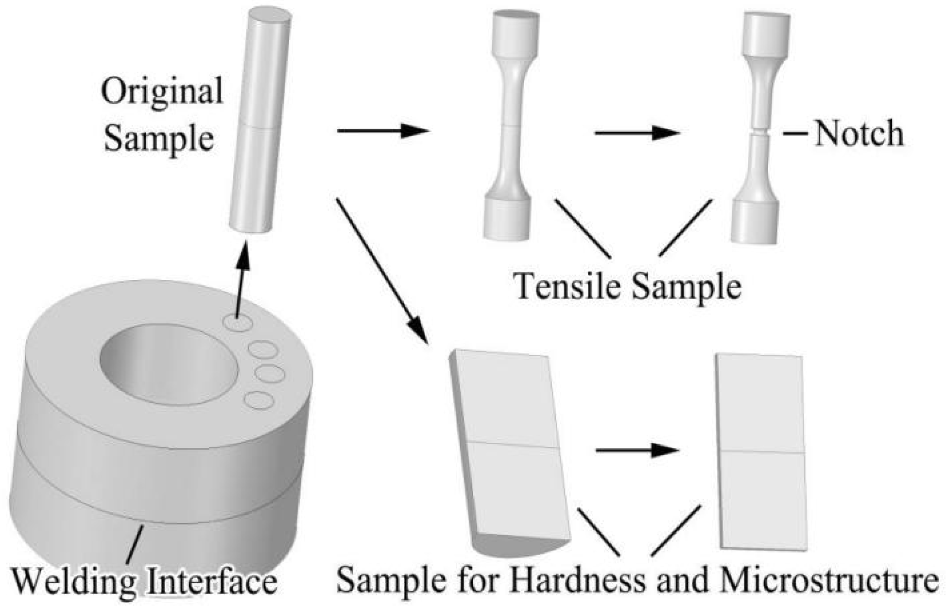
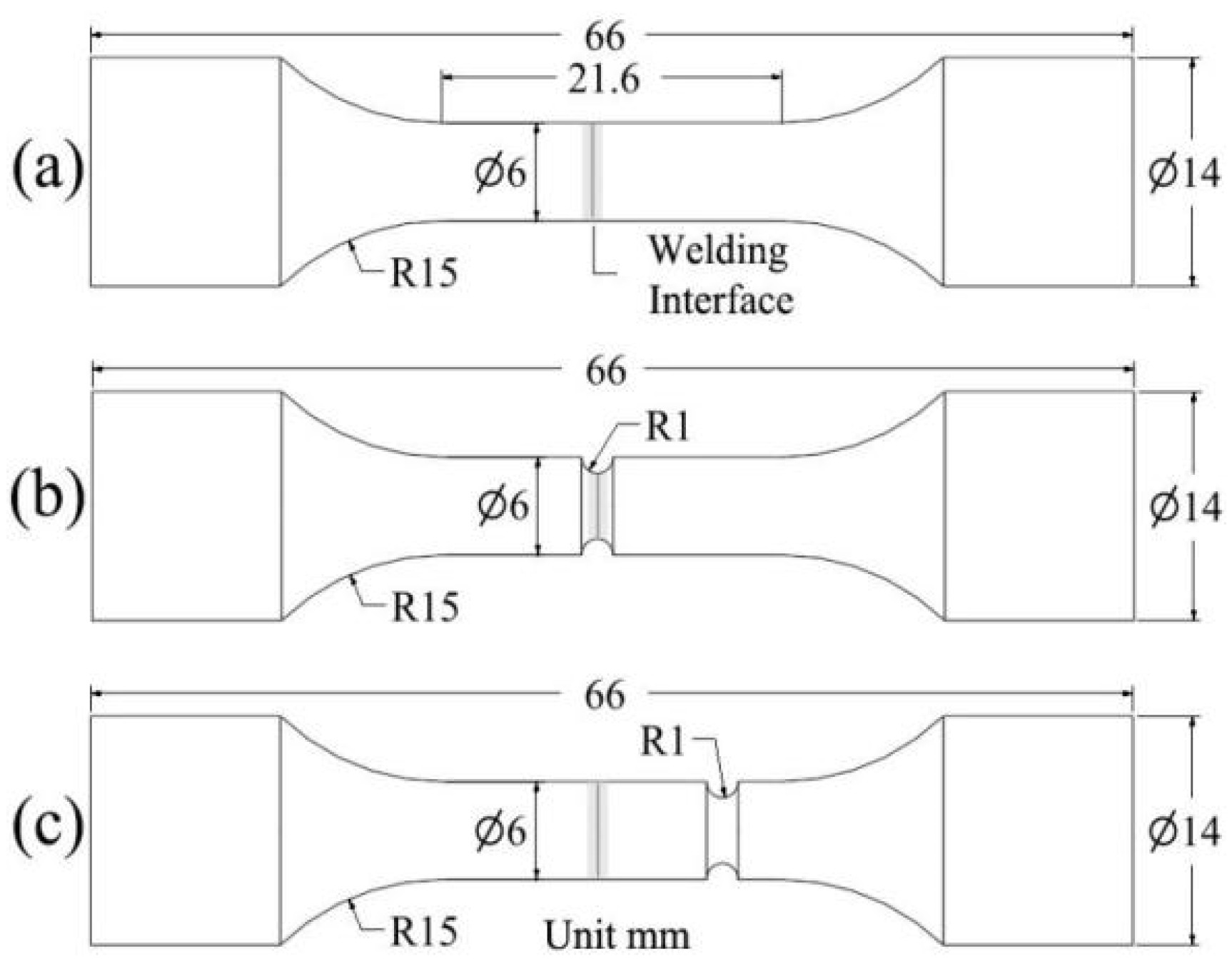
2.1. Material and Sample Preparation

The ring samples of TC21 alloy with inner diameter of 65 mm, outer diameter of 135 mm, and length of 300 mm were prepared, followed by β forging and air cooling process. The β transformation temperature of the TC21 samples was 970 ± 20 °C. Table 1 presents the chemical composition of the material of TC21 alloy. Before welding, the samples were treated by homogenizing and annealing at 850 °C for 2 h. It was confirmed that TC21 alloy material before welding consisted of α + β phase with a basket weave microstructure. The welding process was carried out using HSMZ-130 axial and radial inertia friction welding machine designed by Harbin Welding Institute Limited Company (Harbin, China). The welding parameters are listed in Table 2. The welded samples were followed by post-welding heat treatment at 730 °C for 2 h and then air cooling to room temperature.
Figure 1 shows the acquisition procedure of experimental samples for microstructure and mechanical performance tests. Original bar specimens with dimensions of ϕ15 mm and length of 70 mm were extracted from welded rings by wire electrical discharge machining (WEDM). The original specimens included four zones: weld zone (WZ), thermo-mechanically affected zone (TMAZ), heat-affected zone (HAZ), and base metals (BM), and the weld zone was located in the middle of specimens. Microscopic samples were acquired from original specimens by cutting longitudinally along the axial center, followed by grinding, polishing, and corrosion using the solution of 3% HF+ 3% HNO3+ 94% water. Further, sheet samples with 1 mm thickness were prepared for microhardness measurements. Some original round bar specimens were machined into dumbbell-shaped tensile samples, as shown in Figure 2a. However, during tensile test using samples of Figure 2a, it was found that IFW joints had much higher tensile strength than the base materials. In order to obtain the fracture morphology of joints, the dumbbell-shaped tensile samples were further machined into the samples with groove in the weld zone (WZ:G sample), as shown in Figure 2b. For comparison with WZ:G samples, the samples with groove in the base metal (BM:G sample) were prepared, as shown in Figure 2c.

2.2. Test Methods

Microstructure analysis of TC21 base material and IFW joint was carried out using SU8100 scanning electron microscope (SEM) (Hitachi High-Tech Corporation, Tokyo, Japan). Microhardness measurements were conducted using 401MVD Vickers microhardness tester (Wolpert Wilson Instruments, Aachen, Germany) under 100 g load exposed for 5 s. The test points with adjacent distance 0.5 mm were taken from one side of the base material and across the entire joint zone. The tensile tests for three kinds of samples shown in Figure 3 were performed at room temperature using MTS-793 tensile test machine (MTS, Berlin, Germany) at a crosshead speed of 1 mm/min. After tensile fracture failure, the fracture surface was observed under SU8100 SEM.

3. Results and Discussion
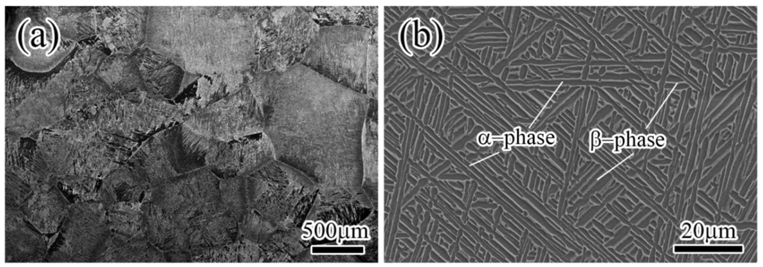
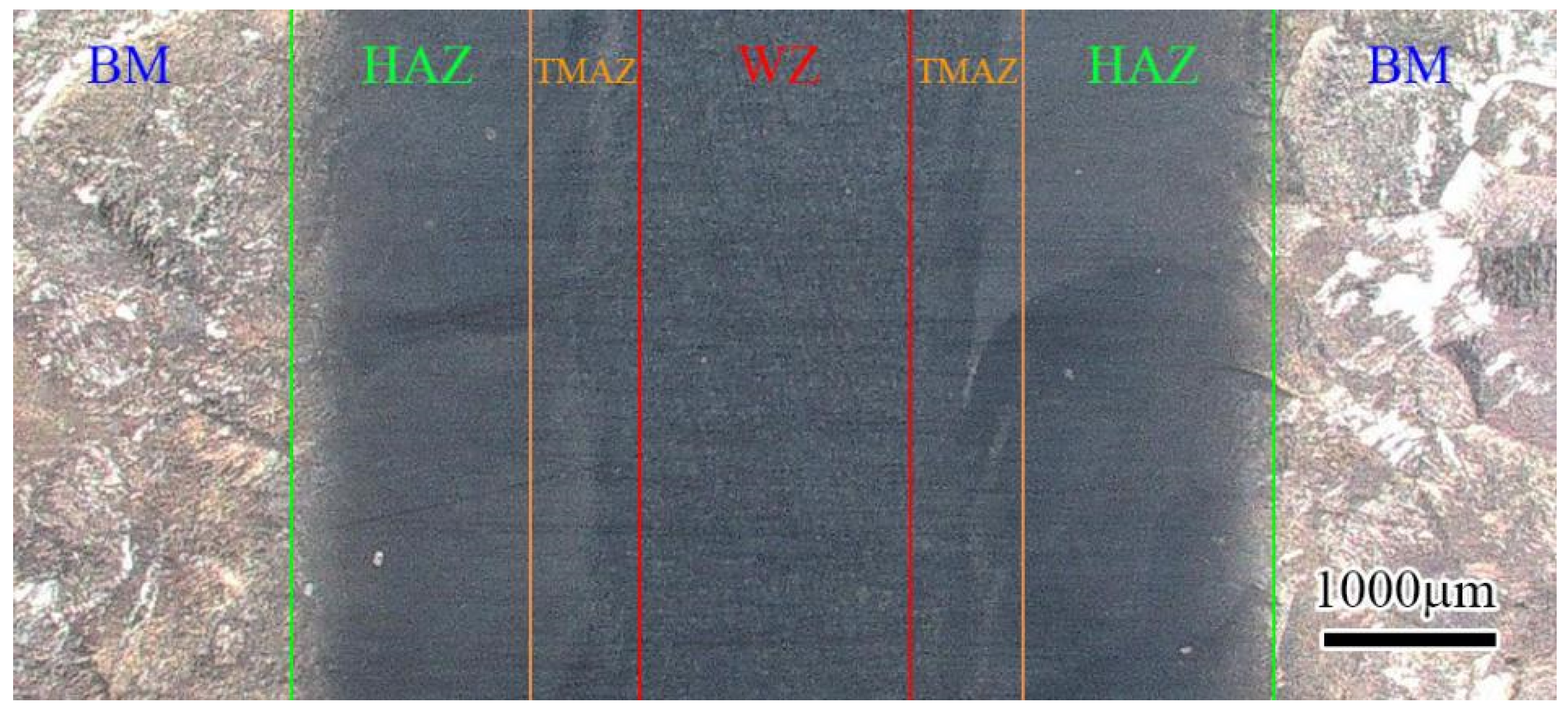
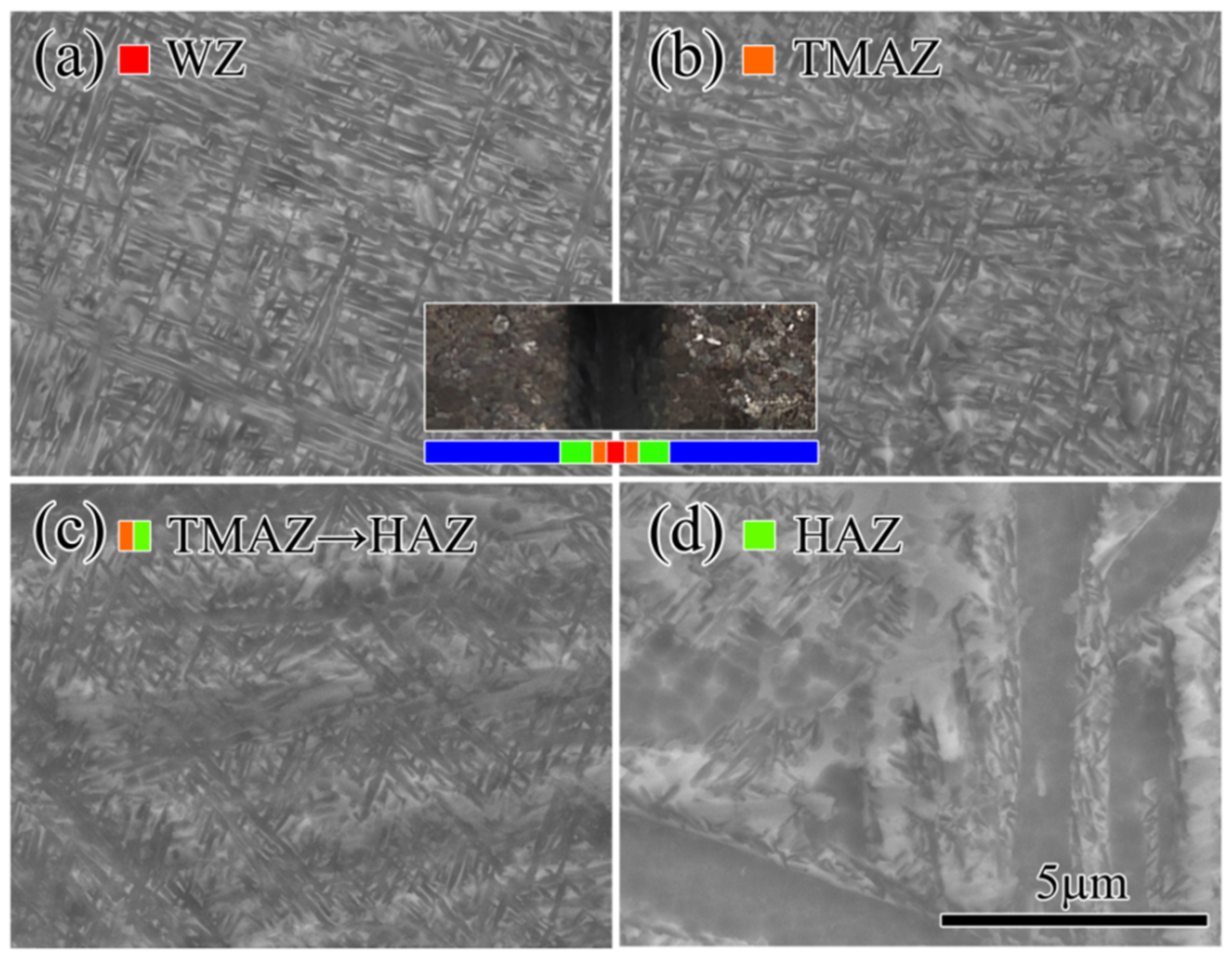
3.1. Microstructure

Figure 3 presents the microstructure of the TC21 base material, which is a typical basket-weave structure consisting of the α + β phase. The main characteristic of the basket-weave structure is that primitive β grains are destroyed in forging deformation, and the acicular α phases inside the β grain boundary are cross-distributed with each other and woven into a basket shape. As shown in Figure 3a, the β phase is a large-size equiaxed grain ranging from 400 to 1500 μm. With a further increase in the magnification of SEM, Figure 3b shows a network of coarse acicular α phase within the grain boundary of the equiaxed β phase, and the size of the coarse acicular α phase is a width of 2 to 4 um and length of 20 to 100 um. The TC21 titanium alloy with this kind of basket-weave microstructure has excellent mechanical properties and high damage tolerance compared to the TC21 alloy with other microstructures.
Figure 4 shows a metallographic photo of the TC21 IFW joint under a low microscope magnification. The total width of the IFW joint is about 5.1 mm. It can be assumed that the microstructure of the joint is symmetrical along the welding interface due to the similar thermal conditions applied to the two parts during the welding process. Different zones of the IFW joint are marked in Figure 4. WZ, with a width of about 1.5 mm, is located in the center of the joint, which became relatively darker than BM after corrosion using a chemical solution. The microstructure of WZ is uniform and obviously different from that of BM. TMAZ, with a width of about 0.5 mm, is located on both sides of WZ. It can be observed that the shape of the β phase in TMAZ is deformed due to friction force. HAZ, with a width of about 1.3 mm, is formed next to TMAZ. The β grains in HAZ are not deformed and almost remain in the β-phase shape of BM, which means HAZ is not affected by rotational friction and is only affected by heat.
Figure 5 displays the microstructures of the different zones of TC21 IFW joints under a high microscope magnification. As shown in Figure 5a, a typical dynamic recrystallization microstructure is formed in the weld zone. Because the temperature of the weld zone is very high during the IFW process, which exceeds the β-transformation temperature of titanium alloy [16], the microstructure of WZ transitions to the uniform fine-needle α phase, and the original basket-weave microstructure with the coarse acicular α phase disappears completely. Figure 5b shows the microstructure of TMAZ, where the basket-weave microstructure almost disappears, but there is a lot of fine-needle α phase precipitated within the β phase base due to high-temperature influence. Figure 5c indicates the microstructure of TMAZ but located far away from the WZ, where the coarse acicular α phase does not disappear completely, but the grain boundaries become indistinct, and there is a lot of precipitated fine-needle α phase. Figure 5d displays the microstructure of HAZ, where the basket-weave microstructure is almost maintained, and there are some precipitated fine-needle α phases.

3.2. Microhardness

The variation of microhardness from WZ to the base metal is shown in Figure 6. The average microhardness of WZ is 430 HV, which is much higher than that of the base metal (330 HV). According to the classical morphology theory, grain refinement is believed to be responsible for the increase in the hardness of WZ. In Figure 6, the microhardness experiences a sudden drop from HAZ to the base metal, not a gradual trend, which means HAZ also has a high microhardness level. We believe the rapid cooling after welding results in heat treatment and a strengthening effect.

3.3. Tensile Properties

In the beginning, tensile tests of dumbbell-shaped samples without grooves shown in Figure 2a were conducted. Figure 7 gives the stress–strain curves of test samples without grooves. The fracture positions for all samples are in the base metal far away from the joint, as shown in Figure 8, so the weakest point is the base metal area when the IFW joints are subjected to axial tensile force, which means the IFW joint has a higher tensile strength than the base metal.
In order to obtain the properties of IFW joints, tensile tests of samples with grooves shown in Figure 2b (WZ:G sample) and Figure 2c (BM:G sample) were conducted. The tensile stress–strain curves of two WZ:G samples and two BM:G samples are shown in Figure 9. For WZ:G and BM:G samples, only the groove positions are different, so the stress statuses are the same during the tensile test. The tensile results show that fracture failure for all groove samples occurs at the bottom of the groove position. Comparing the curves of WZ:G and BM:G samples shown in Figure 9, we can find that the tensile strength of WZ:G samples (about 1850 MPa) is higher than that of BM:G samples (about 1550 MPa), which means IFW joint has about 20% higher tensile strength than the base metal. Moreover, for BM:G samples, fracture failure occurs when the strain is about 2%, lower than the samples without grooves (5–8%), as shown in Figure 7. This can be explained by the stress concentration at the bottom of the groove. However, from the curve trend of BM:G samples, we can still observe the yielding phenomenon. However, for WZ:G samples, there is almost no yielding, and fracture failure happens when the overall strain reaches around 1%. As a result, we can see that the IFW joints have a higher tensile strength than the base metal but have worse plastic performance.
Figure 10 displays the diagrams of tensile fracture morphology for samples with grooves. Figure 10a,b shows SEM diagrams under a low microscope magnification corresponding to BM:G and WZ:G samples, respectively. In Figure 10a, the fracture surface of the BM:G sample is not a cup–cone shape, and there are many “Peaks and Valleys” and a lot of tearing ridges. Thus, the fracture morphology of the base metal can be characterized as a ductile–brittle mixed fracture. However, in Figure 10b, the fracture surface of the WZ:G sample looks relatively flat, and the fracture morphology of the IFW joint is close to brittle fracture. As shown in Figure 10c, further observation of the fracture surface of the WZ:G sample reveals both dissociation planes and dimples. Figure 10d,e shows SEM diagrams under a high microscope magnification corresponding to BM:G and WZ:G samples, respectively. At the same magnification, it can be found that the dimples of the base metal are deeper and larger, while the dimples of the IFW joint are smaller, and some of them are little steps of dissociation.
As shown in Figure 5, a recrystallization microstructure with a uniform fine-needle α phase is formed in the weld zone, which is believed to play an important role in increasing the microhardness and tensile strength of IFW joints. However, the plastic performance of the IFW joint is worse than that of the base material. Figure 5 shows that the α phases in the IFW weld zone increase substantially compared with the base material. As we know, the α phase is a close-packed hexagonal structure, the β phase is a body-centered cubic structure, and normally, the plasticity of a body-centered cubic structure is better than that of a close-packed hexagonal structure. Therefore, the formation of a lot of α phases in the IFW weld zone may result in a decrease in plastic performance. Moreover, a basket-weave structure with coarse acicular α phases maintaining a certain length–width ratio has the best plasticity for TC21 alloy. Therefore, the plasticity decreases when the α phases are too fine and small in the IFW weld zone.

4. Conclusions

(1)
Inertia friction welding (IFW) of TC21 titanium alloy was successfully completed.
IFW joints with a total width of about 5.1 mm, including WZ, TMAZ, and HAZ, were formed. The width of central WZ was about 1.5 mm, and the widths of TMAZ and HAZ were about 0.5 mm and 1.3 mm, respectively. The results show that a very narrow joint was formed using the IFW method.
(2)
The weld zone has a dynamic recrystallization microstructure, which is composed of a uniform fine-needle α phase. The microstructure of TMAZ consists of a β phase base and fine-needle α phase. HAZ almost maintains the basket-weave microstructure of the base metal, but there are many fine-needle α phases precipitated within β phases.
(3)
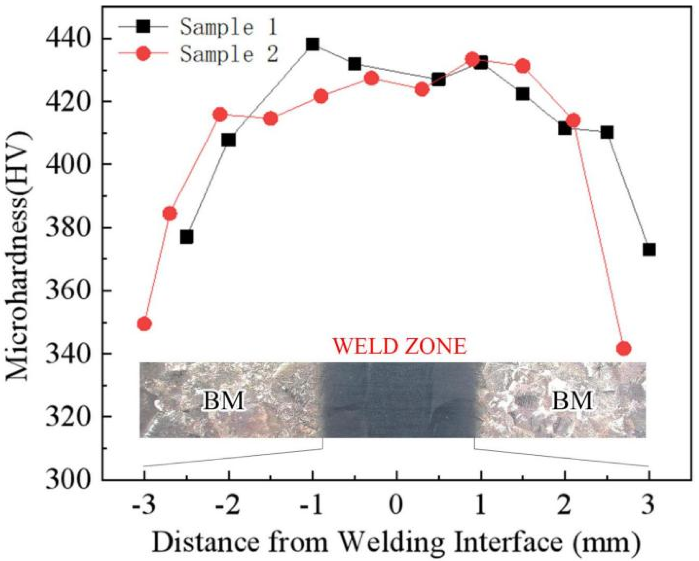
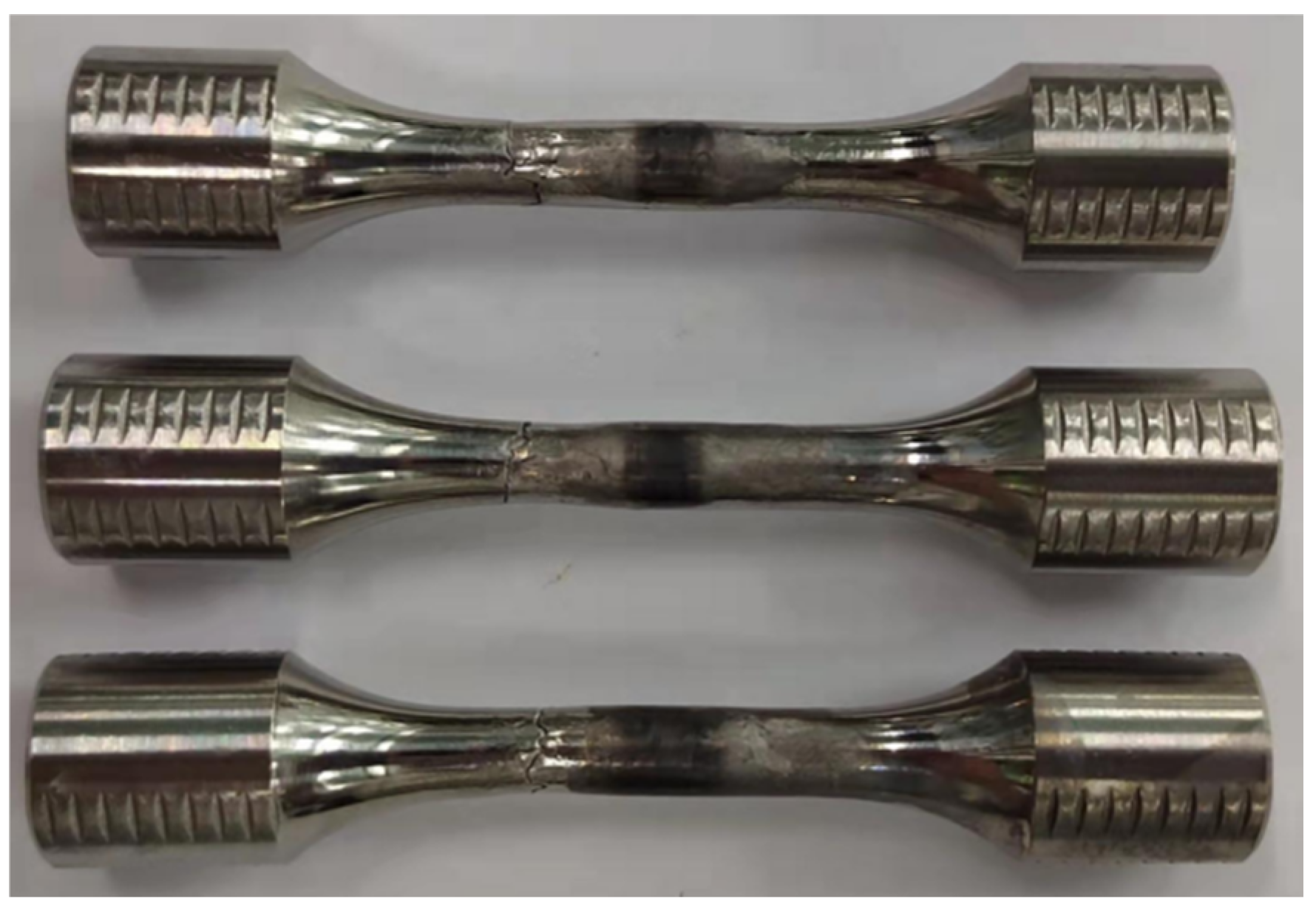
The microhardness of the IFW joint zone is higher than that of the base metal. Tensile tests using normal tensile samples without grooves indicate that the fracture positions in the base metal are all far away from the weld zone. A joint with excellent mechanical properties was formed using the IFW method under suitable parameters.
(4)
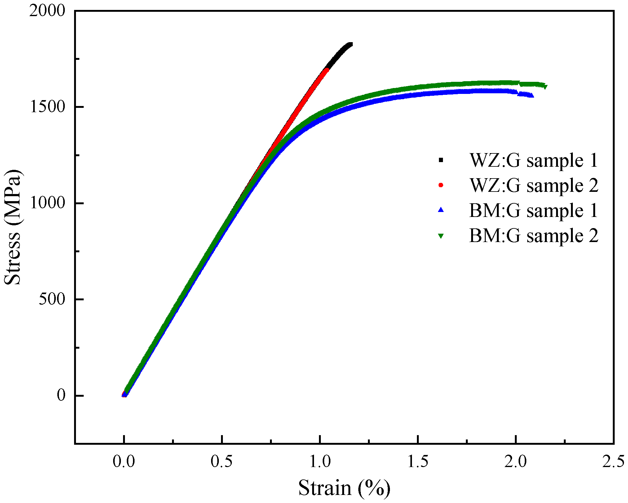
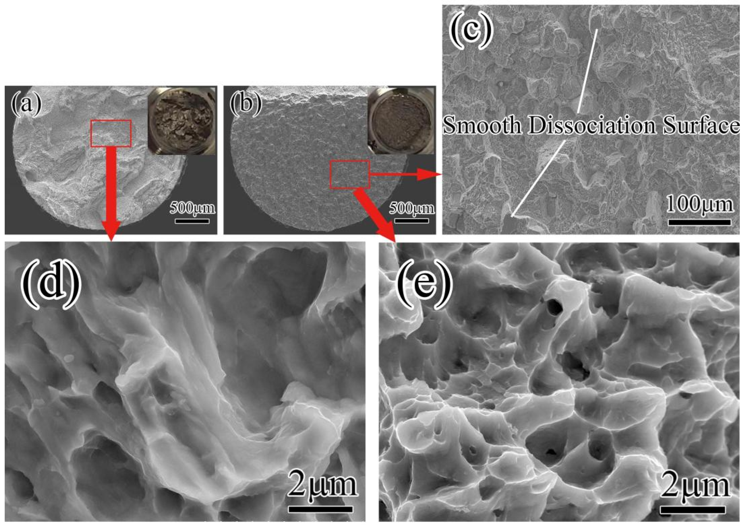
Tensile tests using the samples with grooves were conducted, and the results show that the IFW joint has about a 20% higher tensile strength and lower plasticity than the base metal. Fracture morphology analysis indicates that the fracture of the base metal is a ductile–brittle mixed fracture, and the fracture of the IFW joint is closer to a brittle fracture.
(5)
The microstructure of the uniform fine-needle α phase formed in the weld zone is believed to be responsible for increasing the microhardness and tensile strength of IFW joints. However, too many fine-needle α phases also result in the decreased plasticity of IFW joints compared with the base metal.

Author Contributions

H.W. and F.W. designed and supervised the experiments; Z.L. (Zihao Li) and M.W. performed the experiments; J.Z. was in charge of the welding experiments; S.Z. and Z.L. (Zhijun Li) assisted with sampling and data analyses. H.W. and Z.L. (Zihao Li) contributed to writing and editing the manuscript. All authors have read and agreed to the published version of the manuscript.

Funding

This research was funded by the Shenzhen Science and Technology R & D Fund: JCYJ20190809150001747; Science and Technology Co-operation Projects in Heilongjiang: YS20A19; Post-doctoral Later-stage Foundation Project of Shenzhen Polytechnic: 6020271008K.

Institutional Review Board Statement

Not applicable.

Informed Consent Statement

Not applicable.

Data Availability Statement

All data used to support the findings of this study are included within this article.

Conflicts of Interest

The authors declare no conflict of interest.

References

  1. Li, G.; Chandra, S.; Rashid, R.A.R.; Palanisamy, S.; Ding, S. Machinability of additively manufactured titanium alloys: A comprehensive review. J. Manuf. Process. 2022, 75, 72–99. [Google Scholar] [CrossRef]
  2. Khanna, N.; Zadafiya, K.; Patel, T.; Kaynak, Y.; Rashid, R.A.R.; Vafadar, A. Review on machining of additively manufactured nickel and titanium alloys. J. Mater. Res. Technol. 2021, 15, 3192–3221. [Google Scholar] [CrossRef]
  3. Emiralioğlu, A.; Ünal, R. Additive manufacturing of gamma titanium aluminide alloys: A review. J. Mater. Sci. 2022, 57, 4441–4466. [Google Scholar] [CrossRef]
  4. Wu, Y.Q.; Zhang, C.B.; Zhou, J.; Liangm, W.; Li, Y.L. Analysis of the Microstructure and Mechanical Properties During Inertia Friction Welding of the near-Alpha Ta19 Titanium Alloy. Chin. J. Mech. Eng. 2020, 33, 88. [Google Scholar] [CrossRef]
  5. Hui, L.; Zhao, Y.S.; Zhou, S.; An, J.L.; Wang, L. Analysis of Corrosion Fatigue Properties of Notched Tc21 Titanium Alloy. Rare Met. Mater. Eng. 2020, 49, 2706–2711. [Google Scholar]
  6. Tan, C.S.; Fan, Y.D.; Li, X.J.; Huang, C.W.; He, J.H.; Zhang, G.J. Effect of the Multiscale Lamellar on Mechanical Properties of Tc21 Titanium Alloy. Rare Met. Mater. Eng. 2021, 50, 4410–4417. [Google Scholar]
  7. Song, J.W.; Tan, C.S.; Sun, Q.Y.; Xiao, L.; Zhao, Y.Q.; Sun, J. Effect of Step-Quenching on Microstructure and Mechanical Properties of Tc21 Titanium Alloy. Rare Met. Mater. Eng. 2019, 48, 1260–1266. [Google Scholar]
  8. Wen, X.; Wan, M.; Huang, C.; Tan, Y.; Lei, M.; Liang, Y.; Cai, X. Effect of microstructure on tensile properties, impact toughness and fracture toughness of TC21 alloy. Mater. Des. 2019, 180, 107898. [Google Scholar] [CrossRef]
  9. Li, W.; Vairis, A.; Preuss, M.; Ma, T. Linear and rotary friction welding review. Int. Mater. Rev. 2016, 61, 71–100. [Google Scholar] [CrossRef]
  10. Liu, Y.; Zhao, H.; Peng, Y.; Ma, X. Microstructure and tensile strength of aluminum/stainless steel joint welded by inertia friction and continuous drive friction. Weld. World 2020, 64, 1799–1809. [Google Scholar] [CrossRef]
  11. Yang, J.; Li, J.; Jin, F. Effect of welding parameters on high-temperature tensile and fatigue properties of FGH96 inertia friction welded joints. Weld. World 2019, 63, 1033–1053. [Google Scholar] [CrossRef]
  12. Wen, H.Y.; You, G.Q.; Ding, Y.H.; Li, P.Q.; Tong, X.; Guo, W. Effect of Friction Pressure on Zk60/Ti Joints Formed by Inertia Friction Welding. J. Mater. Eng. Perform. 2019, 28, 7702–7709. [Google Scholar] [CrossRef]
  13. Liu, H.-J.; Feng, X.-L. Microstructures and interfacial quality of diffusion bonded TC21 titanium alloy joints. Trans. Nonferrous Met. Soc. China 2011, 21, 58–64. [Google Scholar] [CrossRef]
  14. Wang, K.; Wu, M.; Yan, Z.; Li, D.; Xin, R.; Liu, Q. Dynamic restoration and deformation heterogeneity during hot deformation of a duplex-structure TC21 titanium alloy. Mater. Sci. Eng. A 2018, 712, 440–452. [Google Scholar] [CrossRef]
  15. Zhou, S.L.; Tao, J.; Gou, D.J. Studying on Appearance of Weld of Fine Grain TC21 Alloy in TIG. J. Mater. Eng. 2009, S1, 69–72. [Google Scholar]
  16. Palanivel, R.; Dinaharan, I.; Laubscher, R.F. Assessment of Microstructure and Tensile Behavior of Continuous Drive Friction Welded Titanium Tubes. Mater. Sci. Eng. A 2017, 687, 249–258. [Google Scholar] [CrossRef]
Figure 1. Acquisition procedure of experimental samples.
Processes 10 00752 g001
Figure 2. Diagram of tensile samples. (a) tensile samples; (b) WZ:G sample; (c) WZ:G sample.
Processes 10 00752 g002
Figure 3. Microstructure of TC21 base materials. (a) SEM images of low magnification; (b) SEM images of high magnification.
Processes 10 00752 g003
Figure 4. Microstructure of the different zones of TC21 IFW joint.
Processes 10 00752 g004
Figure 5. Microstructure of the different zones of TC21 IFW joint.
Processes 10 00752 g005
Figure 6. Variation of microhardness from WZ to base metal of IFW joints.
Processes 10 00752 g006
Figure 7. Stress–strain curves of primary IFW samples.
Processes 10 00752 g007
Figure 8. Diagram of tensile test samples after fracture.
Processes 10 00752 g008
Figure 9. Stress–strain curves of IFW samples with grooves.
Processes 10 00752 g009
Figure 10. Diagrams of tensile fracture morphology for samples with grooves. (a) OM images of the samples BM:G at low multiples; (b) OM images of the samples WZ:G at low multiples; (c) SEM images of the samples WZ:G at low multiples; (d) SEM images of the samples BM:G at high multiples; (e) SEM images of the samples WZ:G at high multiples.
Processes 10 00752 g010
Table 1. Chemical composition of TC21 alloy, wt.%.
AlMoNbSnZrCrFeOCNHSiTi
6.352.752.092.032.061.480.0980.0990.0200.0170.002≤0.13Bal.
Table 2. Inertia friction welding parameters of TC21 alloy.
Initial Rotating Speed (RPM)Moment of Inertia (kg·m2)Friction Pressure (MPa)Upsetting Pressure
(MPa)
70038876102
Publisher’s Note: MDPI stays neutral with regard to jurisdictional claims in published maps and institutional affiliations.

