Abstract
Plate heat exchangers (PHEs) have significant potential to improve energy efficiency in the process industries. However, realizing their full potential to achieve such energy savings requires a systematic approach to screen the many options available. Thus, this work presents a generalized novel approach for the optimal design of both gasket and welded plate heat exchangers, with different plate geometries and flow configurations. A new design method coupled with an optimization framework is proposed to obtain the optimal solution with minimum total transfer area by setting up a series of relations between temperatures among each single-pass block with known inlet and outlet temperatures of process streams. An MINLP mathematical model is developed to select the best combination of the flow pass configuration and available commercial plate geometries within practical design constraints. The differences between the design methodology of gasket and welded PHEs are highlighted. Two case studies are used to demonstrate the proposed method for both gasket and welded PHEs. Results show that better design with reduced heat transfer area by 10.71% and design time by 83.3% is obtained compared with previously proposed approaches.
1. Introduction
Increasing energy consumption and CO2 emissions make it urgent to improve heat transfer efficiency in industries [1,2,3]. This can be achieved by using high-performance heat transfer equipment [4]. Conventional shell-and-tube heat exchange is one of the most commonly used types of heat transfer equipment nowadays among different type of heat exchangers [5,6]. Although the methodologies of design in conventional heat exchangers are relatively mature, it remains challenging to decrease their relatively large approach temperature and big thermal size [6]. Additionally, shell-and-tube heat exchangers can be easily affected by fouling deposition, especially in high-temperature applications, such as crude oil pre-heating [7,8]. Both plate heat exchangers and shell-and-tube heat exchangers offer specific advantages depending on the type of application and industry. However, in terms of energy saving, plate heat exchangers (PHEs) can significantly increase heat recovery through exploitation of small temperature differences, improve thermal-hydraulic behavior, and reduce energy consumption and greenhouse emissions [6,9].
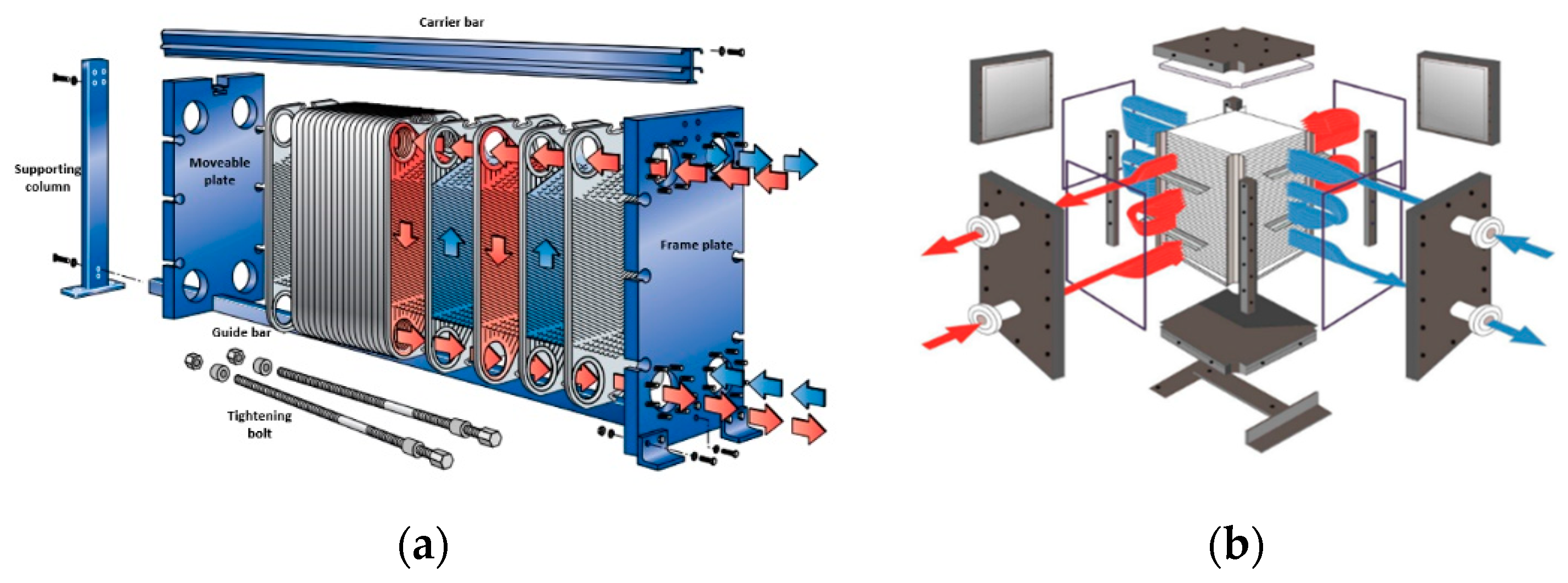
There are many forms of corrugated plate and channel arrangements for PHEs [10]. Fluids stay longer in PHEs when compared with shell-and-tube heat exchangers, since hot and cold streams flow over the entire plates [11]. For a given duty, the total volume and weight of PHEs are three times smaller than those of shell-and-tube heat exchangers [2]. High heat transfer coefficient allows for a minimum approach temperature in PHEs to be as low as 2 °C [6]. Higher heat recovery efficiency, smaller footprint, easier-to-deal-with fouling mitigation and lower capital cost are the main advantages of PHEs over shell-and-tube heat exchangers [6,12]. Gasket plate heat exchangers (GPHEs) and welded plate heat exchangers (WPHEs) are the two main types of PHEs [6], and they have different structures as shown in Figure 1. For GPHEs, the number of plates can be adjusted by adding or removing plates, which gives a flexible thermal design to meet the process requirement [6]. The temperature and pressure allowance of GPHEs are 200 °C and 25 bar respectively [4]. Compared with GPHEs, the integrity of WPHEs is significantly enhanced since plates are welded together. Consequently, WPHEs can tolerate higher temperatures (up to 350 °C) and higher pressures (up to 40 bar), exceeding the gasket limitations [4]. Owing to the unique structure of WPHEs, they are less likely to suffer from leakage issues and are more suitable for rapid-change conditions [13]. Based on these distinct features, PHEs are commonly applied in food, petrochemical plants, and other energy-intensive process industries [14]. With their increasing application in industries, studies of PHEs on their heat transfer behavior are increasing as well. It is important to enhance the thermal-hydraulic behavior of PHEs to reduce the capital cost further and increase energy conversion.

Figure 1.
The structure of PHEs: (a) the structure of a gasket plate heat exchanger; (b) the structure of a welded plate heat exchanger.
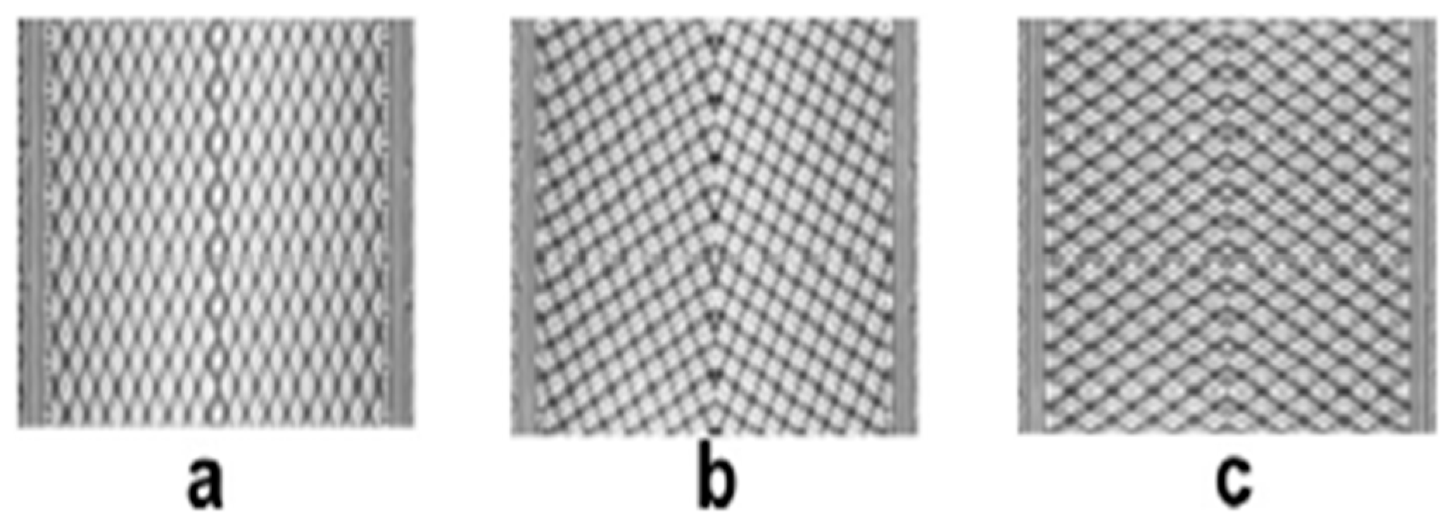
The heat transfer behavior of PHEs is significantly affected by plate geometry, plate type and flow arrangement, which needs to be systematically optimized. In the past few decades, it has been proved that chevron-plates are the most energy-efficient plate type over 60 different types of plates, and commonly used by manufacturers of PHEs [15,16]. Researchers have conducted numerous experimental and numerical studies [17,18,19,20,21,22,23] on how the chevron angle affects heat transfer behavior. Different chevron angles have different Reynolds numbers and friction factors. However, in the process industries, only a small number of fixed chevron angles have been applied as shown in Figure 2. In this work, the three most commonly used channels are used. The H type channel, where the chevron angle is 60°, has the best heat transfer behavior and the largest resistance to flow because of high turbulence intensities and large velocities [21]. The L type channel has a chevron angle of 30°. The small chevron angle leads to lower heat transfer coefficient and pressure drop. M type channels, where the hydraulic resistance and heat transfer performance are between the other two, combines the L and H type channels. Thus, the optimization process should account for the trade-off between heat transfer coefficient and hydraulic resistance.

Figure 2.
Commonly used chevron angles: (a) H type channel (b) M type channel (c) L type channel [3].
The flow arrangement with the best heat transfer behavior needs to be selected depending on the required design criteria. Although piping and maintenance expenses are relatively low for a single-pass flow arrangement, higher heat transfer coefficients are achieved in multi-pass flow arrangements since fluids stay for a longer time in PHEs [24].
One of the most dramatic advantages of PHEs is their flexibility to satisfy the required process conditions by choosing different plate types, plate geometries, and flow arrangements [25]. However, these numerous choices increase the design complexity and the difficulty of searching for the optimal design arrangement. Determination of flow arrangement (pass arrangement for cold and hot streams), plate type and geometry selection, and design constraint considerations (for example pressure drop) are the three key points for the optimum design of PHEs. Most design optimization methods of PHEs are industrially owned, and few are in the open literature.
To develop the thermal design of PHEs, the logarithmic mean temperature difference (LMTD) and ϵ-NTU methodologies are the most commonly used approaches [6]. Cooper [26] and Shah [27] used a trial-and-error method to test different geometries and find the best design solution by employing ϵ-NTU and LMTD approaches. However, these methodologies take a large amount of time, and they fail to include flow arrangement selection. Wang and Sunder [28] presented an optimization design method for PHEs, which adjusted all the possible plate patterns on the plate surface to maximize the utilization of pressure drop. Again, the optimization process failed to consider different flow arrangements, which might obtain a better result for the design with certain constraints. A screening method was proposed by Gut and Pinto [29]. The objective of this method is to get rid of inferior results to overcome the limitation of mixed nonlinear programming (MINLP) problem. The objective of this approach was to minimize the total area with consideration of number of passes, feed location, and number of plates as variables. However, plate pattern selection was not considered. Najafi and Najafi [30] developed an optimization design method of PHEs with multiple objectives by minimizing hydraulic resistance and maximizing total area of PHE simultaneously. This presented challenges to obtain a globally optimal design solution and needs a considerable computation time. Picon-Nunez [31] applied an optimal plate heat exchanger model to heat recovery. The ϵ-NTU method was employed to select flow arrangements and evaluate the temperature correction factor. However, this method failed to consider the plate pattern selection.
Among all factors that affect heat transfer behavior, flow arrangement is the most complex factor to be integrated into the optimization process since the unsymmetrical passes of hot and cold streams may diminish effective temperature differences. Initially, most of the studies [32,33,34] used the LMTD correction factor to solve this problem. A closed-form formula for two-fluid heat recovery was proposed by Pignotti and Shah [35] for the analysis of complex flow arrangements. This method was further improved by Pignotti and Tamborenea [36] by introducing the computer-aided method for calculating the thermal effectiveness of arbitrary flow arrangements by employing a matrix algorithm. The formulas for up to four passes for different flow arrangements relating to the thermal design of PHEs were proposed by Kandlikar and Shah [37]. The details of traditional thermal design methods, including these formulas, are available in plate heat exchanger design handbooks [5].
With the development of computation technologies, Tovazshnyansky et al. [38] proposed a computational method to address different heat transfer arrangements based on blocks of algebraic equations. Arsenyeva et al. [39] further improved this approach. However, for practical application, the geometry of plates cannot be an arbitrary value and plates should be selected from available commercial plates, as assumed. A method of design for multi-pass PHE was proposed by Arsenyeva et al. [3], which includes the selection of plate type by using the ϵ-NTU method in the thermal design. The plate geometry data collected from manufacturers can be used to build a mathematical model to evaluate heat transfer behavior. However, this method requires a large amount of computation time and is better to be applied as a rating problem. Traditionally, since the entering flow rates and stream temperature data are given in a sizing problem, the LMTD method is possibly a better option compared to the ϵ-NTU method to simplify the design process [40]. The ϵ-NTU method might be a favorable option to solve the rating problem, where details of geometries and the size of heat exchangers are fully specified [2,5,6].
Therefore, a comprehensive optimization framework of PHEs should consider plate geometry, plate type, and flow arrangement in the overall design with less computation time. To decrease computation effort, the LMTD approach is firstly applied in this work in the thermal-hydraulic design process by setting up a series of relations between temperatures among each single-pass block with known inlet and outlet temperatures of process streams, which integrated multi-pass flow arrangement, flow geometry, plate type, and chevron angle into automated optimization work. Besides, most of the design methods for PHEs are focused on GPHEs, and only a very few design approaches of WPHE are available. This is because the thermal design of WPHEs is more complex than that of GPHEs [41]. However, in some severe situations, only WPHE can be applied. To overcome the shortcomings of previous work, this paper also presents a generalized automated methodology for the design and optimization of single multi-pass plate heat exchangers, including both GPHEs and WPHEs. The differences of the design of two different types of PHEs are firstly highlighted in this work, so that users can choose the type of PHE according to their needs. The objective is to automatically derive the optimal solution (assumed to be minimum heat transfer area) from various flow arrangements and available sets of commercial plates within the required duty and pressure drop allowance. Two case studies are presented to apply the new design approach for GPHEs and WPHEs.
2. Methods
The objective of this methodology is to optimize a plate heat exchanger by identifying an optimal global solution from different types of flow arrangement, various plate types, and chevron angle for a specified process requirement. The main assumption is that there is no maldistribution between channels and no phase transition. Steady state operation, no longitudinal heat conduction in the plates (only transverse heat conduction), uniform inlet fluid velocity and temperature, constant heat transfer coefficient across the plate, uniformly distributed fouling across the heat transfer area, and constant fluid properties are assumed.
2.1. Detailed Design Methodology of PHEs
The step-by-step methodology of PHEs design is detailed as follows, including how to select the number of passes for the hot and cold streams, plate geometries, and develop the model for thermal-hydraulic performance.
2.1.1. Flow Arrangement Selection
The differences of flow arrangements between gasket plate heat exchangers and welded plate heat exchangers must be distinguished due to their specialized structures. In general, the types of overall flow arrangement for gasket plate heat exchangers include counter-current flow and co-current flow. For a single-pass flow arrangement, pure counter-current flow has higher thermal effectiveness compared with the co-current flow. For a multi-pass flow arrangement, although increasing the number of passes enhances the heat transfer coefficient, it increases the complexity of the thermal design. For welded plate heat exchangers, crossflow and counter-current flow arrangements are achieved locally and globally. Compablocs are one of the most commonly used WPHEs, and the heat transfer coefficient of Compabloc can be as high as five times of conventional shell-and-tube heat exchangers. The number of passes in each stream is optimized by installing baffles into the plate pack.
For a specified pressure drop, the required heat load can be achieved by modifying the flow pass arrangement. The flexible number of plates gives more freedom to the flow arrangement to reach the process requirement [42]. Multi-pass arrangements dramatically increase the heat transfer coefficient, since a large number of passes allows for a greater contact area between the fluids. The pressure drop is increased by increasing the number of passes of streams. Thus, the proposed methodology aims to select the best flow arrangement with the highest heat transfer coefficient within the allowed pressure drop.
As mentioned above, the thermal design of PHEs is more complex when multi-pass flow arrangements are considered. An approach to this problem will now be developed. To obtain a minimum heat transfer area, the optimization process is not straightforward. The key point for calculating overall heat transfer coefficient is to separate multi-pass PHE into parallel blocks, which are assumed to be single-pass PHEs. Pure co-current or counter-current flow arrangement is achieved in each block, and the traditional thermal design method can be further applied to each block.
Consider an Xh-Xc multi-pass plate heat exchanger, in which Xh and Xc represent the number of passes for the hot side and cold side respectively. The total number of blocks N is calculated as Xh × Xc. Figure 3 illustrates an example of a multi-pass PHE, which is separated into six single-pass blocks with three passes on the hot side and two passes on the cold side. Among the six parallel blocks, it can be seen from Figure 3 that Block 1,2,4 are counter-current flow, and Block 3,5,6 are co-current flow. The logarithmic mean temperature difference (LMTD) method is then applied to each single block to obtain thermal-hydraulic performance of the entire heat exchanger. Setting up linear expressions of inlet and outlet temperatures of process fluids among blocks is one of the most important steps in the thermal design.
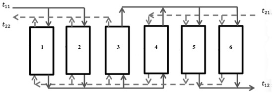
Figure 3.
The six parallel blocks in a multi-pass plate heat exchanger.
For practical applications, the number of passes for each stream cannot exceed four to avoid the extremely high pressure drop. In combination, the total number of different types of flow arrangement is 16. To reduce the number of integer variables and further decrease computation time, each of these 16 different flow arrangements is treated as an independent optimization process. To compare different flow arrangements, enumeration technology is applied to select the best flow arrangement with the minimum total area of PHE.
2.1.2. Plate Pattern Selection
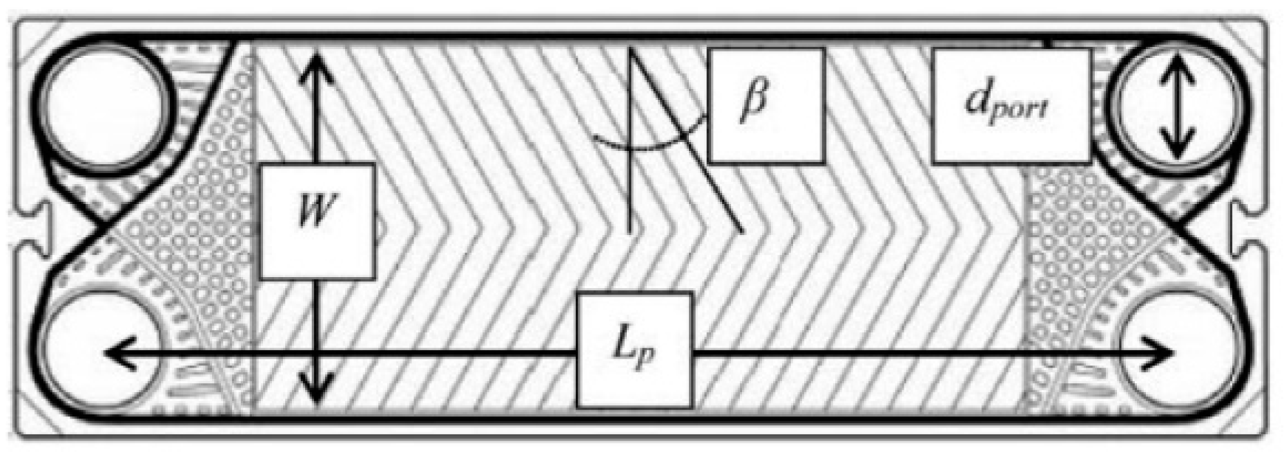
As the most efficient type of plate [43], the chevron plate is employed for the further optimization process. And if another plate type and plate geometry are chosen instead, the optimization process is also applicable since the algorithm itself will not change. The structure of a chevron plate is shown in Figure 4. The plate effective length Lp, plate width W, port diameter dport, chevron angle β are the most important parameters that influence energy efficiency in a chevron-plate design.
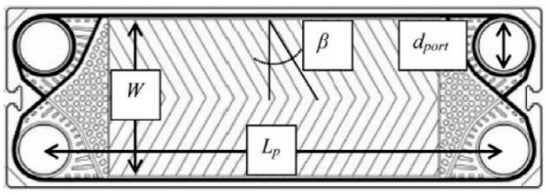
Figure 4.
Structure of chevron plate.
Although key geometries of the plate can be set as continuous variables when designing a chevron plate, the number of available sets of plates are limited in practical application. Only the available plate geometries from industrial manufactures are considered for the further optimization process. The proposed method will automatically choose the best-standardized plate size with the highest heat transfer coefficient from Alfa Laval options. Table 1 summarizes the six widely used plate types for PHEs with detailed geometries, including plate width, plate length, equivalent diameter, and other important plate parameters. As shown in Table 1, the plate geometries are fixed once the plate type is chosen. To account for the effect of plate type on heat transfer behavior, an MINLP model is formulated to select the optimal plate type as the plate geometries are not constant and the correlations for thermal-hydraulic model are non-linear. This increases the difficulty of searching for the global optimum plate pattern and the optimization workload. The details of the MINLP model will be further discussed in the optimization process.

Table 1.
The detailed geometries of five different plate types (20,000 > Re > 250, 12 > Pr > 1) [3].
As mentioned above, heat transfer behavior is sensitive to chevron angles. Thus, the detailed design methodology includes three types of channels with different chevron angle and directly links them with the Nusselt number, as shown in empirical Equation (1) [3].
The parameters m and s, which were obtained by numerical analysis, are not constant but depend on the chevron plate type, on the flow regime, and fluid type (Reynolds and Prandtl numbers). Table 2 lists the values of the two parameters under different situations, which are from literature [3]. Pr is the Prandtl number, µ is viscosity the bulk fluid and µw is the viscosity at the wall.
Table 2.
Parameter of different plate type and channel type for Alfa Laval PHEs [3].
Counting chevron angles and plate types presents 15 different combinations in total. To derive an optimal solution from those combinations automatically, we introduce binary variable sec (PT, CA) to select plate type and chevron angle, where PT and CA are the abbreviations of plate type and chevron angle. To select the optimal combination with maximum heat transfer coefficient and minimum surface area of PHE, the following equation is obtained:
In this equation, the value was 1 if selected and 0 otherwise.
For the welded plate heat exchanger, the plate pattern selection is slightly different. According to Alfa Laval, the chevron angle used in Compobloc is a 45° angle with a 5 mm pressing depth. Thus, only the M type channel can be used in WPHE design.
2.1.3. Thermal-Hydraulic Model
As mentioned previously, this proposed approach applies the LMTD method in term of the thermal design. The general equations to calculate surface area A of PHEs is [5]:
For multi-pass PHEs, A is also related to the number of plates in each block which can be expressed as:
where Q is the total heat transfer load, U is the overall heat transfer coefficient, ∆TLM is logarithmic mean temperature difference, n is number of plates in each block.
Considering the fouling issues, U is expressed as:
in which is the heat transfer coefficient of stream i; is the thickness of the wall; is thermal conductivity of the wall material; is the total fouling resistance.
The empirical correlation in terms of Nusselt number is stated in Equation (1), where the Nusselt number is defined as:
represents the thermal conductivity of the fluid and represents the equivalent diameter of the inter-plate channel, where the channel is defined as the space between the two plates.
in which is the gap between plates, t is the width of the channel. The equivalent diameter should account for the chevron plate corrugation.
The Reynolds number is calculated as:
where is the velocity of the fluid and ρ is the density of fluid:
where is the cross-section area between channels and is the flowrate of the process fluid.
The Prandtl number is:
where is the specific heat capacity of the fluid.
For counter-current flow, Kotjabasakis and Linnhoff [44] described how to simulate a heat exchanger for certain process data, as shown in the following equations.
Combining Equations (11)–(13), the correlations between temperatures of fluids can be derived and stated in Equations (14) and (15). The derivation is detailed in the literature [45].
where is the heat capacity flowrate for the hot stream, is the heat capacity flow rate of the cold stream, and are the inlet and outlet temperatures of the hot stream, and are the inlet and outlet temperatures of cold stream respectively. R represents the ratio of flow heat capacity of cold and hot streams. Equations (18) and (19) list correlations among inlet and outlet temperatures of the hot and cold side. These equations are derived by following the same procedure as mentioned before.
By combining Equations (1)–(20), the heat transfer area A for single-pass PHEs co-current or counter-current flow can be derived for different plate geometries.
For multi-pass PHEs, the key point of the design is to find the relationships among temperatures in the adjacent blocks by applying the LMTD method. In each single block, by employing the above equations the temperatures of streams in any block is linked with the temperatures of streams in its neighboring blocks. In the case of several streams with different temperatures entering the same block, the temperature can be regarded as the average temperature of these streams. Therefore, systematic linear relations of temperatures in the different blocks can be set up. Since the entire PHE is separated into N blocks, the total area of PHE Atotal is equal to N·A.
Pressure drop performance is significantly affected by the plate geometries and the number of passes of each stream. Thus, the hydraulic and thermal performance of plate heat exchangers needs to be included in the optimal design simultaneously. To achieve better heat transfer performance, the utilisation of pressure drop is preferred to be minimised. The pressure drop is expressed as:
In which f represents the Fanning friction factor, and the expression for f is shown in the Equations (22) [46], LP is plate length for pressure drop. The chevron angle and intermediate variable , affect the Fanning friction factor. The intermediate variable is determined by the Reynolds number.
For laminar flow ((Re < 2000),
For turbulent flow (Re > 2000)
To account for the different expressions of and , a binary variable is introduced to define the different range of Reynolds number.
The other part of the pressure drop comes from the height change, which is defined as:
where is the density of the fluid, g is the acceleration due to gravity, H is the equivalent height of fluid passing through. However, since the height of a PHE is comparably small, can be regarded as the total pressure drop of PHEs.
Because it has been assumed that there is no maldistribution of flow in different channels, the pressure drop in the channels is equal. Thus, the total pressure drop is expressed as:
2.2. Optimization Model of Plate Heat Exchangers
For the optimization process, the optimal solution should not only meet the process requirements but also consider the economic cost [47]. As shown in Equation (25) [48], there is a direct relation between capital cost and total area of PHE. The objective of this proposed method is to minimize the heat transfer area in a multi-pass plate heat exchanger.
To obtain the optimal solution for a single multi-pass PHE, a mixed-integer non-linear programming (MINLP) problem is formulated and solved with the ANTIGONE solver in GAMS. ANTIGONE is one of the most widely used global solvers for MINLP optimization [49]. To minimize the total area of a PHE, the general problem is shown in Equation (26). Among all the variables, the integer variables include the total number of plates in each block, the number of passes for the cold and hot side, plate geometries, and chevron angle. There are two constraints. One constraint is that the total heat transfer should be not less than the required heat transfer since the area of the plate is an integer. Pressure drop should be maintained in the allowable range is the other constraint.
where is the total area of the PHE, is the chevron angle, n is the number of plates in each block, is the gap between plates, is the equivalent diameter, Ab is the area of each single plate, is process heat transfer requirement, and is the maximum pressure drop allowance.
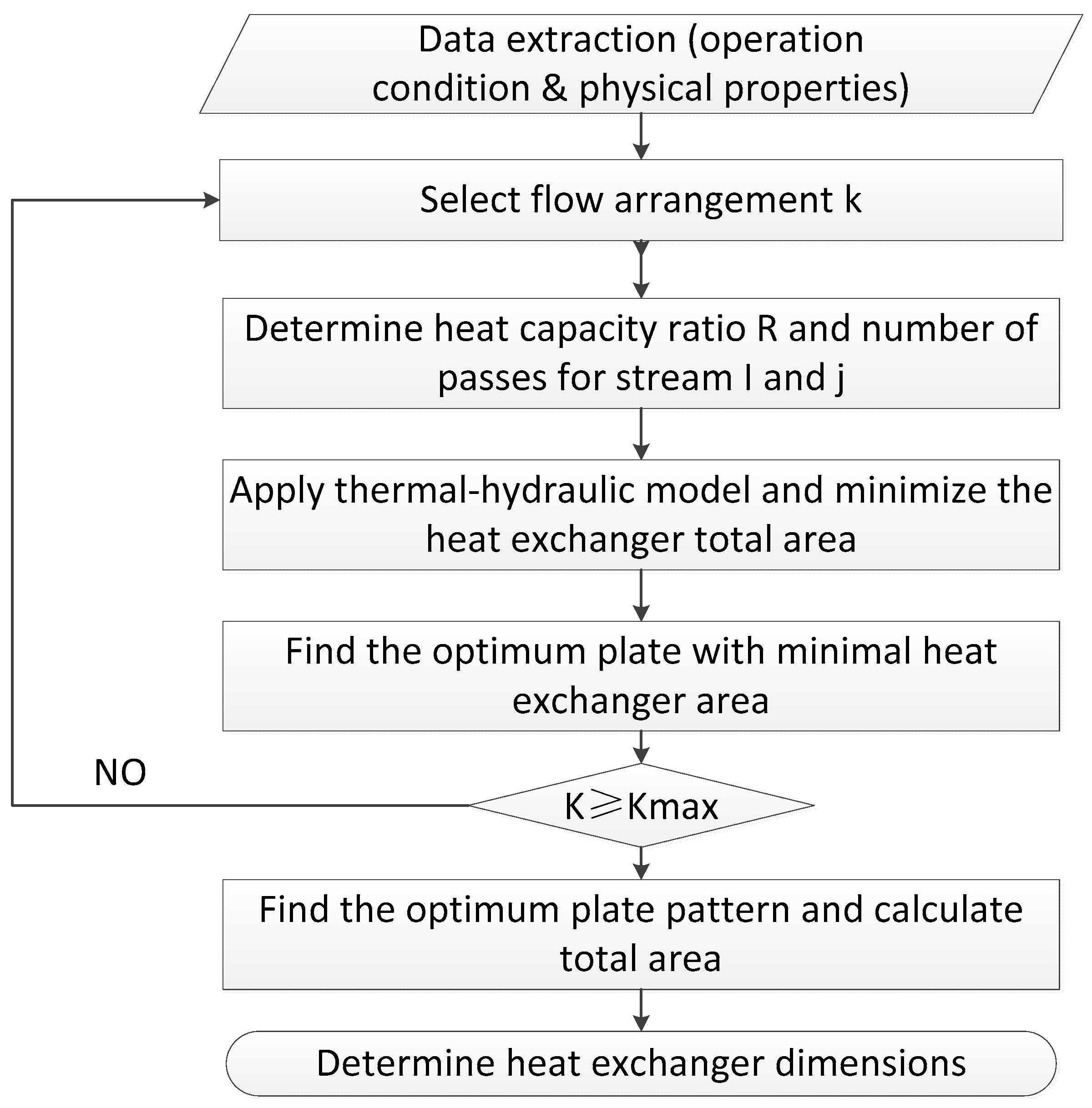
The overall algorithm of the new optimization method for the design of single multi-pass plate heat exchangers is shown in Figure 5. After extracting the specific operating conditions and physical properties from the required design process, the first step is to select a certain flow arrangement. Also, the local minimum heat exchanger area can be derived from automatically selecting the best configurations from all available plate geometries for a specific pressure drop allowance. Kmax is the maximum types for flow arrangement, which is 16. Thus, when the number of iteration K < Kmax, repeat this process. This process is then repeated for the other 15 different types of flow arrangement and the global optimum result with minimum heat transfer area of the PHE is obtained by comparing all local optimum results.
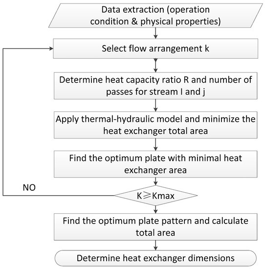
Figure 5.
Overall design algorithm of plate heat exchangers.
3. Case Study
3.1. Case Study 1: Optimization Design of Gasket Plate Heat Exchanger
3.1.1. Verification of the New Design Methodology
A case from Arsenyeva [3] is used to verify and test the accuracy of the new optimization-based design method for gasket plate heat exchangers. The stream properties data are summarized in Table 3. The cold side distillery wash fluid needs to be heated from 28 °C to 90.5 °C by hot water with the inlet temperature of 95 °C. The for both sides is 1.0 bar.
Table 3.
The stream properties of cold side and hot side.
The key point of verification is to fix plate patterns in different flow arrangements as M6M and keep the numbers of chevron angle the same as the literature [3]. The comparison of results between the basic design method [3] and new proposed method with fixed plate pattern are given in Table 4. When applying the proposed design methodology, the results imply the minimum heat transfer area of PHE is 5.04 m2 with 36 plates in M channel and the number of passes for the hot stream and cold streams is 2 and 4 respectively. It is concluded that the results are consistent with the literature [3] for a fixed plate pattern. Having validated the new proposed design model, it will be further applied in the optimization process of a single multi-pass PHE design.
Table 4.
The comparison of fixed pattern design between literature [3] and proposed method.
3.1.2. The Computer-Aided Optimization Process of a Multi-Pass GPHE Design
The same case study as Section 3.1.1 is used to apply the new optimization design method of a single multi-pass GPHE. The optimization process is executed in GAMS with the ANTIGONE solver. The computation time is only 1–2 min for the optimization process for a particular flow arrangement. However, it takes several hours to derive the best solution with minimum area in the published literature [3].
Table 5 shows the optimization results for design of a GPHE under different flow arrangements. The results imply that the flow arrangement 2–3 gives the minimum heat transfer area of 4.5 m2 within the required heat load and pressure drop allowance. The optimal solution is achieved by using 30 M6 type of plates. By comparison, Arsenyeva et al. [3] obtained the minimum area of 5.04 m2 with 38 plates to satisfy the same process requirement. The results indicate that the M6 plate have better thermal-hydraulic performance than the M6M plate and hence the reduction of heat transfer surface from 5.04 m2 to 4.50 m2. Another reason why there is a difference between the proposed method and literature is due to the round-up process to find the minimum number of plates in each block. Differences between the heat transfer equations, between the LMTD and -NTU methods for thermal design for a multi-pass gasket PHE and the effect of locations of the inlet fluids on process behavior are other possible reasons that cause the differences in the results. Therefore the optimization solutions obtained within the required process constraints illustrate the capability of the proposed method to give a feasible global result with higher energy efficiency. The proposed method significantly decreases the computation time from several hours to 20 min for the entire optimization work of plate heat exchanger design.
Table 5.
The optimization results of a multi-pass GPHE design.
3.2. Case Study 2: Optimization Design of Welded Plate Heat Exchanger
This case study from the literature [50] was studied to provide insights into the application of the proposed method into a welded plate heat exchanger design. A pump around stream and crude oil from the hot end of the pre-heat train are the two process streams in this case. The physical properties data of crude side and hot side are listed in Table 6.
Table 6.
A case study from the pre-heat train.
The optimized areas of a multi-pass welded plate heat exchanger under different flow arrangements with optimal plate type are listed in Table 7. The optimization results show that the minimum area is 25.92 m2, which is achieved by a X1 = 2 and X2 = 3 flow arrangement. The total number of plates is 108, and the corresponding plate type is M10B with the spacing of plates δ = 2.5 mm.
Table 7.
The optimization results of a multi-pass welded plate heat exchanger design.
The second-best solution is achieved at X1 = 3, X2 = 2 with 210 number of M6 type plates. The spacing of plates is δ = 2 mm, which is smaller than the spacing of M10B type of plate. For practical considerations, the optimal solution depends on the size of the area, piping arrangement, the volume of the instalment. Thus, design engineers can choose among the best solutions based on the different requirements.
The flow rate of process fluids are two important indicators that can test whether the design is robust or not [45]. In the current design methodology, the flow rates of the cold side and hot side are fixed. To investigate the influence of flow rate on model output, sensitivity analysis is an effective method [10]. Thus, a sensitivity analysis is carried out by adjusting the flow rates for both hot side and cold side. In the meantime, keeping the flow arrangement as X1 = 1 and X2 = 1 reduces the complexity of the model and saves computation time. The results of a sensitivity analysis by varying the flow rate of the hot and cold side in the range of ±50% are listed in Table 8 and Table 9. The results show that when the flow rate of the hot stream decreases from 51.6 kg/s to 45.15 kg/s, the plate type changes from M15B to M6. According to the analysis results, the parameter has a significant impact on the result. Thus, it can be concluded that the optimal design is robust to ±20% flow of the hot stream but much more robust for the flow of the cold stream.
Table 8.
Sensitivity analysis of the flow rate of hot stream.
Table 9.
Sensitivity analysis of the flow rate of cold stream.
4. Conclusions
A new generalized optimization methodology is proposed to design multi-pass plate heat exchangers, including gasket plate heat exchangers and welded plate heat exchangers. The main features that determine plate heat exchanger thermal and hydraulic performance are considered simultaneously by employing discontinuous expression of Nusselt number and friction factor. The basic plate geometries and the number of plates are set as integer variables for minimization of total heat transfer area. The flow arrangement selection is integrated to the thermal-hydraulic model by using the enumeration method, which simplified the optimization workload and saved computation time. Thus, an MINLP model has been created in GAMS using the ANTIGONE solver by considering standardized plate size and the unique heat transfer and pressure drop performance for different plate patterns.
The differences between the designs of two different type PHEs are highlighted. The design engineers can choose the type of PHEs based on the different requirements. Two case studies from literature show the possibility of applying proposed design methodology into the gasket and welded plate heat exchangers. The minimum heat exchanger area can be achieved under a given heat load. Better design with reduced heat transfer area by 10.71% and design time by 83.3% is obtained compared with literature. It can be concluded that the proposed method gives a feasible solution with higher energy efficiency. This is mainly because the proposed method is able to select the plate type with better thermal-hydraulic performance. Due to the LMTD being more suitable for a sizing problem, the proposed method is able to reduce the iteration time. Sensitivity analysis is applied to test the design methodology of welded plate heat exchangers. The results show that within the ± 20% flow of the hot stream the design is robust, but much more robust for the flow of the cold stream. The limitation of this proposed method is that no phase changed is assumed. Thus, for further research work, the methodology can be extended to multi-pass plate heat exchanger design with phase change.
Author Contributions
Conceptualization, R.S.; methodology, K.X.; software, K.X.; validation, K.X.; formal analysis, K.Q.; investigation, K.X.; resources, K.Q.; writing—original draft preparation, K.X.; writing—review and editing, R.S. and H.W.; supervision, R.S. All authors have read and agreed to the published version of the manuscript.
Funding
This paper received no external funding.
Institutional Review Board Statement
Not applicable.
Informed Consent Statement
Not applicable.
Data Availability Statement
Not applicable.
Conflicts of Interest
The authors declare no conflict of interest.
Nomenclature/Abbreviation
| PHE | plate heat exchanger |
| GPHE | gasket plate heat exchanger |
| WPHE | welded plate heat exchanger |
| LMTD | logarithmic mean temperature difference |
| NTU | number of transfer units |
| MINLP | mixed integer nonlinear programming |
| Re | Reynold number |
| Nu | Nusselt number |
| Pr | Prandtl number |
| Symbols | |
| Lp | plate length |
| W | plate width |
| Dport | port diameter |
| de | equivalent diameter |
| Ab | plate area |
| fch | cross-section area |
| μ | dynamic viscosity |
| λ | heat conductivity |
| A | heat transfer area |
| N | total number of blocks |
| X | number of passes for stream |
| h | heat transfer coefficient |
| Q | heat load |
| ∆TLMTD | logarithmic mean temperature difference |
| ⍴ | stream density |
| v | stream velocity in each channel |
| t | width of channel |
| Rf | fouling resistance of streams |
| g | flow rate of the stream |
| a | cross-section area between channels |
| T | temperature |
| CP | heat capacity |
| R | the ratio of flow heat capacities of streams |
| Atotal | total heat transfer area |
| f | friction factor |
| ∆Pheight | pressure drop of height change |
| ∆Pfriction | pressure drop due to friction |
| H | height |
| U | heat transfer coefficient |
| Q0 | required heat load |
| Greek symbol | |
| δ | inter-plate gap |
| 𝛽 | chevron angle |
| Subscript | |
| b | block |
| h | hot stream |
| c | cold stream |
| w | wall |
| 1 | inlet |
| 2 | outlet |
| max | maximum |
References
- Cui, Z.; Lin, H.; Wu, Y.; Wang, Y.; Feng, X. Optimization of Pipeline Network Layout for Multiple Heat Sources Distributed Energy Systems Considering Reliability Evaluation. Processes 2021, 9, 1308. [Google Scholar] [CrossRef]
- Sundén, B.; Manglik, R.M. Plate Heat Exchangers: Design, Applications and Performance; Wit Press: Southampton, MA, USA, 2007. [Google Scholar]
- Arsenyeva, O.P.; Tovazhnyansky, L.L.; Kapustenko, P.O.; Khavin, G.L. Optimal design of plate-and-frame heat exchangers for efficient heat recovery in process industries. Energy 2011, 36, 4588–4598. [Google Scholar] [CrossRef] [Green Version]
- Kakac, S.; Liu, H.; Pramuanjaroenkij, A. Heat Exchangers: Selection, Rating, and Thermal Design; CRC Press: Boca Raton, FL, USA, 2012. [Google Scholar]
- Shah, R.K.; Sekulic, D.P. Fundamentals of Heat Exchanger Design; John Wiley & Sons: Hoboken, NJ, USA, 2003. [Google Scholar]
- Ali, S.S.; Arsad, A.; Hossain, S.K.; Basu, A.; Asif, M. Energy Optimization and Effective Control of Reactive Distillation Process for the Production of High Purity Biodiesel. Processes 2021, 9, 1340. [Google Scholar] [CrossRef]
- Coletti, F.; Macchietto, S. A dynamic, distributed model of shell-and-tube heat exchangers undergoing crude oil fouling. Ind. Eng. Chem. Res. 2011, 50, 4515–4533. [Google Scholar] [CrossRef]
- Berce, J.; Zupančič, M.; Može, M.; Golobič, I. A Review of Crystallization Fouling in Heat Exchangers. Processes 2021, 9, 1356. [Google Scholar] [CrossRef]
- Wang, T.; Luan, W.; Wang, W.; Tu, S.-T. Waste heat recovery through plate heat exchanger based thermoelectric generator system. Appl. Energy 2014, 136, 860–865. [Google Scholar] [CrossRef]
- Guo, Y.; Wang, F.; Jia, M.; Zhang, S. Modeling of plate heat exchanger based on sensitivity analysis and model updating. Chem. Eng. Res. Des. 2018, 138, 418–432. [Google Scholar] [CrossRef]
- Mehrabian, M. Construction, performance, and thermal design of plate heat exchangers. Proc. Inst. Mech. Eng. Part E J. Process Mech. Eng. 2009, 223, 123–131. [Google Scholar] [CrossRef]
- Elmaaty, T.M.A.; Kabeel, A.; Mahgoub, M. Corrugated plate heat exchanger review. Renew. Sustain. Energy Rev. 2017, 70, 852–860. [Google Scholar] [CrossRef]
- Yoon, W.; Jeong, J.H. Development of a numerical analysis model using a flow network for a plate heat exchanger with consideration of the flow distribution. Int. J. Heat Mass Transf. 2017, 112, 1–17. [Google Scholar] [CrossRef]
- Mota, F.A.; Ravagnani, M.A.; Carvalho, E. Optimal design of plate heat exchangers. Appl. Therm. Eng. 2014, 63, 33–39. [Google Scholar] [CrossRef]
- Abu-Khader, M.M. Plate heat exchangers: Recent advances. Renew. Sustain. Energy Rev. 2012, 16, 1883–1891. [Google Scholar] [CrossRef]
- Amalfi, R.L.; Vakili-Farahani, F.; Thome, J.R. Flow boiling and frictional pressure gradients in plate heat exchangers. Part 1: Review and experimental database. Int. J. Refrig. 2016, 61, 166–184. [Google Scholar] [CrossRef]
- Zhong, Y.; Deng, K.; Zhao, S.; Hu, J.; Zhong, Y.; Li, Q.; Wu, Z.; Lu, Z.; Wen, Q. Experimental and numerical study on hydraulic performance of chevron brazed plate heat exchanger at low Reynolds number. Processes 2020, 8, 1076. [Google Scholar] [CrossRef]
- Khan, T.; Khan, M.; Chyu, M.-C.; Ayub, Z. Experimental investigation of single phase convective heat transfer coefficient in a corrugated plate heat exchanger for multiple plate configurations. Appl. Therm. Eng. 2010, 30, 1058–1065. [Google Scholar] [CrossRef]
- Neagu, A.A.; Koncsag, C.I. Model Validation for the Heat Transfer in Gasket Plate Heat Exchangers Working with Vegetable Oils. Processes 2022, 10, 102. [Google Scholar] [CrossRef]
- Shaji, K.; Das, S.K. Effect of plate characteristics on axial dispersion and heat transfer in plate heat exchangers. J. Heat Transf. 2013, 135, 041801. [Google Scholar] [CrossRef]
- Vafajoo, L.; Moradifar, K.; Hosseini, S.M.; Salman, B. Mathematical modelling of turbulent flow for flue gas–air Chevron type plate heat exchangers. Int. J. Heat Mass Transf. 2016, 97, 596–602. [Google Scholar] [CrossRef]
- Kılıç, B.; İpek, O. Experimental investigation of heat transfer and effectiveness in corrugated plate heat exchangers having different chevron angles. Heat Mass Transf. 2017, 53, 725–731. [Google Scholar] [CrossRef]
- Kumar, B.; Soni, A.; Singh, S. Effect of geometrical parameters on the performance of chevron type plate heat exchanger. Exp. Therm. Fluid Sci. 2018, 91, 126–133. [Google Scholar] [CrossRef]
- Hesselgreaves, J.E. Compact Heat Exchangers: Selection, Design and Operation; Gulf Professional Publishing: Houston, TX, USA, 2001. [Google Scholar]
- Promvonge, P.; Tongyote, P.; Skullong, S. Thermal behaviors in heat exchanger channel with V-shaped ribs and grooves. Chem. Eng. Res. Des. 2019, 150, 263–273. [Google Scholar] [CrossRef]
- Cooper, A.; Usher, J.D. Plate heat exchangers. In Heat Exchanger Design Handbook; Hemisphere Publishing Corporation: London, UK, 1983. [Google Scholar]
- Shah, R.; Focke, W. Plate heat exchangers and their design theory. In Heat Transfer Equipment Design; Shah, R.K., Subbarao, E.C., Mashelkar, R.A., Eds.; Hemisphere Publishing: Washington, DC, USA, 1988; pp. 227–254. [Google Scholar]
- Wang, L.; Sunden, B. Optimal design of plate heat exchangers with and without pressure drop specifications. Appl. Therm. Eng. 2003, 23, 295–311. [Google Scholar] [CrossRef]
- Gut, J.A.; Pinto, J.M. Optimal configuration design for plate heat exchangers. Int. J. Heat Mass Transf. 2004, 47, 4833–4848. [Google Scholar] [CrossRef]
- Najafi, H.; Najafi, B. Multi-objective optimization of a plate and frame heat exchanger via genetic algorithm. Heat Mass Transf. 2010, 46, 639–647. [Google Scholar] [CrossRef]
- Picón-Núñez, M.; Martínez-Rodríguez, G.; Lopez-Robles, J. Alternative design approach for multipass and multi-stream plate heat exchangers for use in heat recovery systems. Heat Transf. Eng. 2006, 27, 12–21. [Google Scholar] [CrossRef]
- Cocks, A. Plate heat exchanger design by computer. Trans. Inst. Chem. Eng. Chem. Eng. 1969, 47, C193. [Google Scholar]
- Kumar, H. The plate heat exchanger: Construction and design. In Proceedings of the First UK National Conference on Heat transfer, Leeds, UK, 3–5 July 1984; Volume 86, pp. 1275–1288. [Google Scholar]
- Zinger, N.; Barmina, L.; Taradai, A. Design of plate heat exchangers for heat supply systems. Therm. Eng. 1988, 35, 141e5. [Google Scholar]
- Pignotti, A.; Shah, R. Effectiveness-number of transfer units relationships for heat exchanger complex flow arrangements. Int. J. Heat Mass Transf. 1992, 35, 1275–1291. [Google Scholar] [CrossRef]
- Pignotti, A.; Tamborenea, P.I. Thermal effectiveness of multipass plate exchangers. Int. J. Heat Mass Transf. 1988, 31, 1983–1991. [Google Scholar] [CrossRef]
- Kandlikar, S.G.; Shah, R.K. Asymptotic effectiveness-NTU formulas for multipass plate heat exchangers. J. Heat Transf. 1989, 111, 314–321. [Google Scholar] [CrossRef]
- Tovazhnyanskii, L.; Kapustenko, P.; Pavlenko, V.; Derevyanchenko, I.; Babak, T. The optimum design of multi-pass dismountable plate heat exchangers. Chem. Pet. Eng. 1992, 28, 354–359. [Google Scholar] [CrossRef]
- Arsenyeva, O.; Tovazhnyanskyy, L.; Kapustenko, P.; Khavin, G. Mathematical modelling and optimal design of plate-and-frame heat exchangers. Chem. Eng. Trans. 2009, 18, 791–796. [Google Scholar]
- Wright, A.; Heggs, P. Rating calculation for plate heat exchanger effectiveness and pressure drop using existing performance data. Chem. Eng. Res. Des. 2002, 80, 309–312. [Google Scholar] [CrossRef]
- Arsenyeva, O.P.; Tovazhnyanskyy, L.L.; Kapustenko, P.O.; Khavin, G.L.; Yuzbashyan, A.P.; Arsenyev, P.Y. Two types of welded plate heat exchangers for efficient heat recovery in industry. Appl. Therm. Eng. 2016, 105, 763–773. [Google Scholar] [CrossRef]
- Fodor, Z.; Varbanov, P.S.; Klemeš, J.J. Total site targeting accounting for individual process heat transfer characteristics. Chem. Eng. Trans. 2010, 21, 49–54. [Google Scholar]
- Kumar, V.; Tiwari, A.K.; Ghosh, S.K. Effect of chevron angle on heat transfer performance in plate heat exchanger using ZnO/water nanofluid. Energy Convers. Manag. 2016, 118, 142–154. [Google Scholar] [CrossRef]
- Kotjabasakis, E.; Linnhoff, B. Sensitivity tables for the design of flexible processes. Pt. 1: How much contingency in heat exchanger networks is cost-effective? Chem. Eng. Res. Des. 1986, 64, 197–211. [Google Scholar]
- Smith, R. Chemical Process: Design and Integration; John Wiley & Sons: Hoboken, NJ, USA, 2005. [Google Scholar]
- Martin, H. A theoretical approach to predict the performance of chevron-type plate heat exchangers. Chem. Eng. Process. Process Intensif. 1996, 35, 301–310. [Google Scholar] [CrossRef]
- Taal, M.; Bulatov, I.; Klemeš, J.; Stehlík, P. Cost estimation and energy price forecasts for economic evaluation of retrofit projects. Appl. Therm. Eng. 2003, 23, 1819–1835. [Google Scholar] [CrossRef]
- Guo, K. Optimisation of Plate/Plate-Fin Heat Exchanger Design. Ph.D. Thesis, University of Manchester, Manchester, UK, 2015. [Google Scholar]
- Misener, R.; Floudas, C.A. ANTIGONE: Algorithms for continuous/integer global optimization of nonlinear equations. J. Glob. Optim. 2014, 59, 503–526. [Google Scholar] [CrossRef]
- Tamakloe, E.K.; Polley, G.T.; Picón-Núñez, M. Design of Compabloc exchangers to mitigate refinery fouling. Appl. Therm. Eng. 2013, 60, 441–448. [Google Scholar] [CrossRef]

Publisher’s Note: MDPI stays neutral with regard to jurisdictional claims in published maps and institutional affiliations. |
© 2022 by the authors. Licensee MDPI, Basel, Switzerland. This article is an open access article distributed under the terms and conditions of the Creative Commons Attribution (CC BY) license (https://creativecommons.org/licenses/by/4.0/).