1. Introduction
This paper emphasizes the usefulness of accurate regression rate formulae in developing the hybrid combustion system of a rocket.
In developing performing hybrid combustion-based rockets, the fuel regression rate plays the most important role in the preliminary design of the combustion system, i.e., to predict the geometrical dimensions of the solid fuel, the initial mass of oxygen and fuel, the thrust at sea level and the combustion time and, more important, the time-dependent parameter values of the combustion system. The most accurate regression rate formula must include the relationship between the position of the surface (interface of solid fuel–flowing flue gases) where combustion happens (usually defined by the inner diameter of a cylindrical fuel port), the related average regression rate along the combustion interface and the time for a given fuel/oxidizer couple. Actually, there are no theoretical models and/or refined experiments that can give accurate, predictable time-dependent values for the regression rate. The difficulties are related to the real-time accurate measurements depending on the scale of the experiments, on the ratio O/F (oxygen mass flow rate per fuel mass flow rate) and on the fuel nature and its spatial structure, especially the size and the geometry of the combustion interface. The research in this domain follows mainly two directions, one to find/develop new fuels, pure or compounds, with higher regression rates; and the second one to refine/develop the experimental measurement techniques for the regression rates with better accuracy in space and time. For instance, ref. [
1] presents a regression rate model which is valid for vaporizing fuels in a cylindrical grain configuration without char or melt strata, the comparison with existing published data is reasonable; ref. [
2] HTPB polymer has been characterized through its ballistic properties, mechanical tests, and thermochemical evaluations. The authors of ref. [
3] used a pressurized combustion chamber to determine the regression rate of a hybrid fuel using two flow measuring methods, the throttling to measure the flue gas flow and the weight loss method to determine the O/F ratio; the authors of ref. [
4] wrote a review regarding the experimental measuring methods to evaluate the regression rates, based on 104 references, with special attention given to measurements of very fast processes, i.e., direct high speed photography, ultrasound techniques and X-ray radiography, and microwave and laser methods with high spatial and temporal resolution of the transient regression rate. The authors of ref. [
5] analyze the progress made regarding hybrid rocket engines for outer space and include propellant types, different oxidizer propellants; and emphasize the potential future trends and technical prospects following the main goal of comparison between different available hybrid propulsion technologies and those under development.
The data, including the regression rate formulae, are relatively poor, bearing in mind the special applications such as for space exploration.
Table 1 include some averaged regression rate formulae available in the open access literature. Specific information regarding experimental obtained regression rate equations could be found for instance in [
6] for paraffin, in [
7] for HTPB (Thiokol), in [
8] for HTPB and HTPB+19.7%Al, in [
9] for HTPB+20%GAT, in [
10] for PMMA, in [
11] for HDPE and PE Wax, in [
12] for HTPB+13%nanoAl and paraffin without or with 13%nanoAl.
The hybrid rocket propulsion system concept: the combustion system includes two vessels connected by a mechanically controlled valve; one pressurized containing the liquid oxidizer and the other one holds the solid fuel, designed to have inside it a suitable combustion chamber; during combustion, the oxidizer enters the combustion chamber where it vaporizes and then reacts very powerfully with the fuel; the combustion process is very complex because is not one of volume, it develops at the interface between the solid fuel and the gaseous phase (oxidizer/flue gases), depending on real-time interface chemistry (fuel heating, vaporizing/pyrolysis, burning) and on the flue gases local flow temperature and local composition and on the time-dependent geometrical interface position. The experimentally developed equation for hybrid combustion shows that the regression rate (the “speed” of the burning interface in mm/s) is dependent on the oxidizer mass flux rate (the ratio of the oxidizer mass flow rate to the inlet cross-sectional flow area of combustion volume) in kg/m2s. These experimental observations say that the combustion process is very sensitive to the ratio of oxidizer mass flow rate to the burning fuel mass flow rate. In contrast, for instance, the regression rate in a solid rocket motor is proportional to the combustion chamber pressure. The hybrid rocket engines are safer by comparison to solid ones because the combustion process can be safely stopped by closing the valve of the oxidizer. These rockets are less complex than liquid rocket engines.
This paper presents a preliminary engineering design of a hybrid rocket’s combustion system, based on the regression rate. The design is applied for the hybrid combustion system using pure HTPB and gaseous oxygen. The design involved three main constraints, constant regression rate during combustion, constant oxygen mass flow rate and constant O/F ratio. They were predicted by the initial inner and outer fuel port diameters, the initial mass of the fuel and oxygen, the combustion time, the thrust at sea level, and, the time-related functions of the regression rate, fuel and oxygen mass flow rates, the thrust and the mass of the combustion system. All these evaluations used the formula of the regression rate and shaped the correlation during combustion between this regression rate, the variable inner fuel port diameter giving the position of combustion interface and the time. It was assumed that the regression rate formula applies at any time of combustion. This extra imposed hypothesis has not been valid until now because the experiments were organized to evaluate the average regression rate. These evaluations can also be applied to other fuel/oxygen couples, knowing the adequate equation of the regression rate.
2. Preliminary Design Mathematical Setting
Consider the geometry of a cylindrical fuel port, see
Figure 1.
The initial geometry is given through inner and outer diameters, di and do, and length L.
The main basic mathematical relationship between the real-time regression rate, the real-time inner diameter (position of the combustion interface between flue gases and solid fuel) and the time is:
where, d is the inner diameter during combustion,
[m/s] is the real-time regression rate and t is time.
It was assumed that the regression rate at any given time during combustion is identical to the averaged regression rate, as in
Table 1:
where, Gox (gaseous oxygen) is the real-time oxygen mass flux [kg/m
2s],
[kg/s] is the real-time oxygen mass rate,
[kg/s] is the real-time mass rate of the fuel, d is the real-time inner diameter [m], L [m] is the length of the fuel port, ρ is the fuel density [kg/m
3], O/F is the real-time ratio of mass rates of oxygen and fuel, a and n have values experimentally obtained and supposed constant at any time of combustion.
The Equations (1) and (2) should be correlated by imposing initial design constraints and adopting input values of initial combustion system parameters.
2.1. Preliminary Engineering Initial Compulsory Design Constraints
The above compulsory design constraints allow the evaluation of the initial combustion system parameters, i.e., the initial inner diameter of the fuel, di, the initial mass flow rates of fuel and oxygen, and , and the initial thrust (at sea level) Ti for all three preliminary design cases.
The initial inner diameter, d
i.
The initial mass flow rate of the fuel,
.
The initial mass flow rate of the oxygen,
.
The initial thrust (at sea level) T
i.
2.2. Preliminary Engineering Design for a Constant Regression Rate,
The real-time variable parameters are assessed using integrated Equation (1) and the imposed constant regression rate. Thus, the real-time inner diameter d, the real-time mass flow rates of fuel and oxygen, the real-time thrust T and, the real-time (O/F) ratio are computed.
The real-time inner diameter during combustion, d.
The real-time fuel mass flow rate during combustion,
.
The real-time oxygen mass flow rate during combustion,
.
The real-time thrust during combustion, T (it is supposed c = ct.).
The real-time O/F ratio during combustion.
The Equation (6) allows the evaluation of the combustion time, t
c.
where:
The outer diameter, d
o, of the fuel port, can be evaluated through either Equation (12) or Equation (18).
The design constraint of the constant regression rate during combustion asks for a very specific control device for the mass flow rate of the oxygen according to Equation (14). The design gives the largest possible initial mass of the oxygen, i.e., largest Mo,i/Mf,i ratio. Thus we get a heavy rocket, because the real-time needed O/F ratio is increasing during combustion from 3.2 to values 2 to 4 times larger. In any case, the combustion time has the smallest possible values.
2.3. Preliminary Engineering Design for a Constant Oxygen Mass Flow Rate,
Equation (1) is integrated through Equation (2) to obtain the time function of the inner diameter of the fuel port during combustion, d.
The time-varying parameters are evaluated using integrated Equation (20) and the imposed constant oxygen mass flow rate, and the real-time regression rate, the real-time mass flow rate of fuel, the real-time thrust T and the real-time (O/F) ratio are obtained.
The real-time regression rate during combustion,
.
The real-time fuel mass flow rate during combustion,
.
The real-time thrust during combustion, T (it is supposed c = ct.).
The same Equation (6) also allows the evaluation of the combustion time, t
c.
where:
The outer diameter, d
o, of the fuel port, can be found through Equations (20) or (27) for t = t
c.
The design constraint of the oxygen constant mass flow rate during combustion asks for the simplest specific control device for the mass flow rate of the oxygen according to the compulsory design constraint The design, however, gives a large initial mass of the oxygen, i.e., large Mo,i/Mf,i ratio, but the combustion time has larger values than in the case of a constant regression rate.
2.4. Preliminary Engineering Design for a Constant (O/F) Ratio, (O/F) = (O/F)i = 3.2 = ct
The Equation (1) is integrated through the Equation (2), to obtain the real-time inner diameter of the fuel port during combustion, d.
The variable parameters in this case are the real-time regression rate, the real-time mass flow rates of the fuel and of the oxygen and the real-time thrust T. They are subtracted using integrated Equation (29) of the real-time inner fuel diameter during combustion and the imposed constant (O/F)i ratio.
The real-time regression rate during combustion,
.
The real-time regression rate during combustion,
.
The real-time oxygen mass flow rate during combustion,
.
The real-time oxygen mass flow rate during combustion,
The same Equation (6) also allows the evaluation of the combustion time, t
c.
where:
The outer diameter, d
o, of the fuel port, can be known directly either through Equation (29) or involving Equation (35) for t = t
c.
The design constraint of constant O/F ratio during combustion needs a very specific control device of the mass flow rate of oxygen accordingly to the compulsory design constraint (O/F) = (O/F)i = 3.2 = ct. The design gives the smallest initial mass of oxygen, i.e., smallest Moi/Mfi ratio, and the combustion time has the largest values, compared to the case of a constant regression rate and a constant mass flow rate of oxygen.
3. Preliminary Rocket Design Assumptions
The design of the hybrid combustion system was presented as an example in
Section 2. The real preliminary design of the combustion system must evaluate primarily the extra thrust demand during rocket flight. The extra thrust has to assure the acceleration of the rocket during the combustion time to the required final velocity. This extra thrust has to balance the variable weight and inertia force of the rocket and the variable friction force between the air and the outer surface of the rocket. The inertia force of the rocket during the flight might be imposed. The remaining extra thrust to balance the opposite friction force depends on the rocket’s aerodynamics, on the variable air parameters and on the variable rocket velocity. The extra thrust balancing only the variable friction force between the air and the outer surface of the rocket can be assessed step by step, by adopting the cumulative mass of the dead rocket mass (e.g., the constant mechanical structure transporting all masses) and the constant useful mass and the variable cumulative mass of fuel and oxygen. The equation of this extra thrust is particularized below for a vertical flight.
where
is the cumulative mass of the dead rocket mass and the useful mass (supposed 25% of initial cumulative mass of fuel and oxygen) and
is the variable cumulative mass of fuel and oxygen during flight and, 1.5 g is the cumulative acceleration (due to gravitation, 1 g, and inertia, 0.5 g).
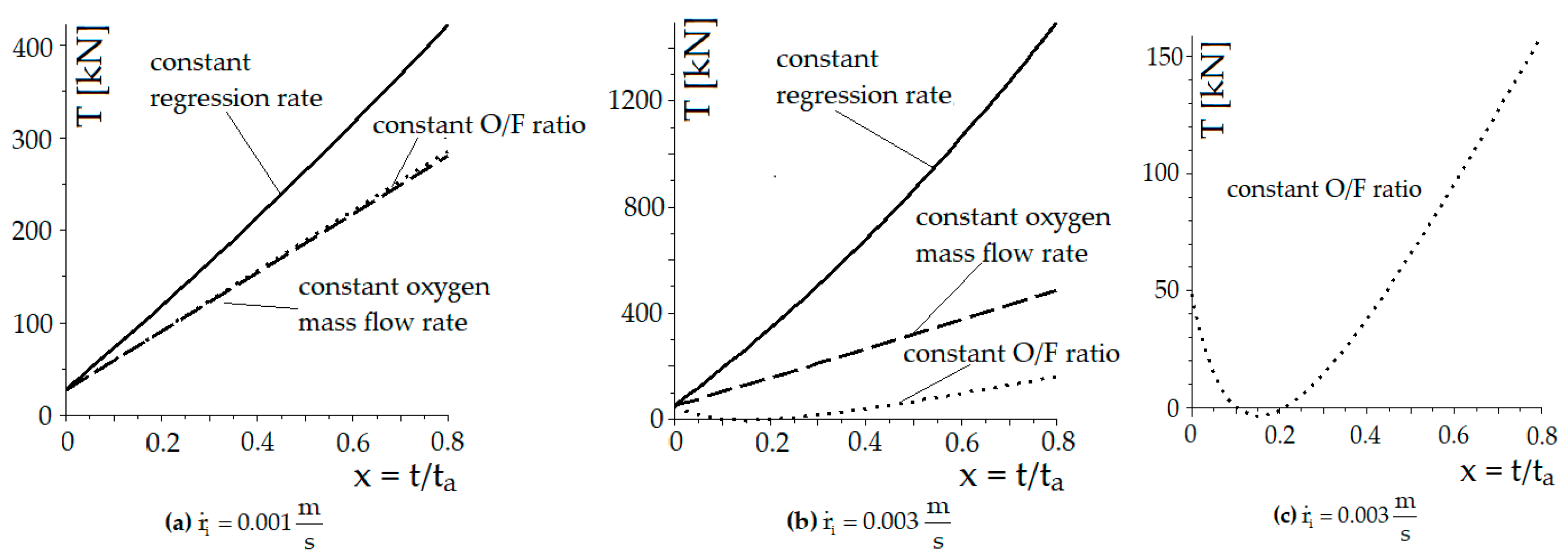
The numerical results are included in
Figure 2.
The numerical results show how sensitive the extra thrust is in balancing the friction force to the imposed constraints and adopted values of cumulative whole rocket mass. Surprisingly, the smaller regression rates might be better than larger ones, especially for a preliminary design with a O/F constant ratio where a minimum below 0 kN was found, see
Figure 2c. However, it is obvious that larger regression rates assure larger thrust.
4. Discussions
The experimentally developed equation for hybrid combustion shows that the regression rate (the “speed” of the burning interface in mm/s) is dependent on the oxidizer mass flux rate (the ratio of the oxidizer mass flow rate to the inlet cross-sectional flow area of combustion volume) in kg/m
2s. These experimental observations suggest that the combustion process is very sensitive to the ratio of oxidizer mass flow rate to the burning fuel mass flow rate. Therefore, the preliminary design of hybrid rocket engines (a hybrid combustion system with liquid oxidizer and solid fuel) must be performed through the regression rate. At this moment, there are no available accurate regression rate formulae. The actual main research includes experimental measurement techniques for the very fast oxidation processes of fuels used in hybrid combustion systems [
4].
The paper develops an engineering approach for hybrid combustion systems designed for rockets. The mathematical settings must have very accurate formulae for the fuel regression rate depending on the combustion interface position and time, and suitable for the chosen fuel/oxidant couple.
By imposing the regression rate (experimentally or theoretically evaluated), the preliminary engineering design of a hybrid combustion system might be performed through engineering constraints controlling the combustion process, either the constant regression rate, or the constant of oxygen mass flow rate or the constant O/F ratio. The constant regression rate gives the largest thrust, the constant O/F ratio gives the smallest. However, the constant regression rate gives the largest Mo,i/Mf,i ratio, i.e., heavy rockets, while the constant O/F ratio gives the smallest one.
The chosen design constraints must be verified through the intermediary of the needed extra thrust, considering all the initial cumulative mass of the rocket, the variable mass of the oxygen and fuel during flight, and the variable friction force during the flight, depending on the air parameters, on the rocket velocity and on the aerodynamics. The needed extra thrust must be evaluated considering the real-time trajectory of the rocket in the gravitational field. A true preliminary engineering design has to include the mathematical settings revealed in this paper as a step in a two-step design; the design of the hybrid combustion including a verification of the flue gas velocity and thus, the extra available thrust and then a refined/adapted preliminary design of the hybrid combustion system for the rocket’s application.
Comparing the obtained numerical results, they show that:
All cases are feasible for hybrid rocket engines;
The initial parameters, di, mf,i, mo,i, Ti, are identical for all similar cases (identical regression rate and length);
As the regression rate grows larger, the combustion time becomes smaller;
Rockets with constant regression rates can carry the largest weights and the smallest ones for a constant O/F ratio;
Constant regression rate and constant O/F ratio need mechanical devices in order to assure the oxygen mass flow rate demands, see
Figure 3.
This engineering model needs refined experiments with real-time improved measurements in order to find out whether the regression rate Equation (2) might be applied with admissible accuracy or if the regression rate must have time-dependent predictable values for a and n.
5. Conclusions
This paper presents an engineering preliminary design for a hybrid rocket combustion system, based on the regression rate. The design evaluates the initial inner and outer fuel port diameters, the initial mass of the fuel and oxygen, the combustion time, the thrust at sea level and the time-dependent functions of the regression rate, fuel and oxygen mass flow rates, the thrust and the mass of the combustion system. It was assumed that the regression rate formula applied at any time of combustion. These evaluations can also be applied for other fuel/oxygen couples, knowing the adequate equation of the regression rate.


