Article

Numerical Investigation of the Cleaning Flame Jet and Formation of the Molten Pool in the Corner Scarfing Process of the Casting Slab

1
State Key Laboratory of Advanced Special Steel, Shanghai Key Laboratory of Advanced Ferrometallurgy, School of Materials Science and Engineering, Shanghai University, Shanghai 200444, China
2
Shanghai Donsern Metallurgy & Technology Co., Ltd., Shanghai 201900, China
*
Author to whom correspondence should be addressed.
Processes 2022, 10(4), 798; https://doi.org/10.3390/pr10040798
Submission received: 16 March 2022 / Revised: 8 April 2022 / Accepted: 14 April 2022 / Published: 18 April 2022

Abstract

:
The corner defects in the casting slab greatly influence the product quality. These defects may extend during the heating and rolling process and even result in the discarding of the rolled plate as scrap. A corner cleaning equipment based on the scarfing machine is proposed to eliminate the defects in slab corners for producing high-quality steel. Unlike the flat surface scarfing process, the flame jet and the shape of the molten pool have an essential impact on the effectiveness of the flame cleaning in the corner of the casting slab. A three-dimensional fully coupled model for the flame cleaning nozzle is developed to simulate the flow pattern of the flame jet, Oxygen concentration distribution, and temperature field in the corner of the slab. The simulated flame jet flow field and temperature results agreed well with the factory trial results. Additionally, a three-dimensional thermal model for simulation of the molten pool formed by flame cleaning in the corner of the casting slab has also been developed. For the sake of simplicity, the 2D elliptic and 3D Gauss heat source models are used to simulate the flame heating on the upper and right surfaces of the slab corner and the reaction heating between oxygen and heated iron along the corner, respectively. The simulation results show that the length is 58.1 mm and 57.9 mm on both sides and the corner melting depth is 29.9 mm. The error is 7.04%. The numerical simulation results showed good agreement with the factory trial results, indicating that the proposed models of the flame jet and the heat sources analysis are feasible to study the flame cleaning process of the slab corner, it provides the scientific theoretical basis for the design and practical application of corner scarfing machine.

1. Introduction

As the surface quality of slab and hot-rolled strips can be considered one of the critical quality parameters, special attention should be paid to producing advanced steel satisfying the most striking quality demands. One main factor affecting the surface quality is the corner defects commonly resulting from slab corners formed during continuous casting. A quick solution to surface defects is auto surface cleaning or corner cleaning, namely the scarfing process. It can improve cleaning quality and working efficiency and create conditions for the slab’s hot delivery and hot charging process.
Scarfing is a complex thermochemical process in which the surface defects can be burned out and removed from the casting slab. The principle of scarfing is based on a chemical reaction of oxygen with the base metal at elevated temperatures. The steel in the corner of the slab is heated locally via a high-temperature flame obtained from natural gas and oxygen combustion. When reaching the ignition point, the steel is melted by a jet creating a continuous chemical reaction between the iron and the oxygen. The slag (iron oxide) is blown away by the oxygen jet using a special cleaning nozzle.
In recent years, with the application of the scarfing machine, more and more scholars have begun to study the scarfing process. Surface scarfing is a highly complex process in which the multi-phase turbulent flow, flame jet, chemical reaction, heat transfer, melt, and solidification can be completed in this process. Li et al. [1,2,3,4,5] conducted many studies on optimizing the surface jet flame and the design of the scarfing machine. They simulated and studied the distribution of pressure field and velocity field for the flame jet on the slab surface, which was used to predict how the surface metal was removed and the formation reason of surface grooves. Qi et al. [2] studied the phenomenon of jet flow from packed holes. They found that the streams mixed under the Coanda effect, which made the multi-jet flow gradually merge into a single jet, which provided a basis for optimizing the nozzle. Chen et al. [3] found that the jet direction, the deflector angle, and the nozzle height all affect the impinge grooves, and it is unrealistic to eliminate them completely. There are also many scholars who study the basic theory of flame cleaning. Egon et al. [6] developed a nozzle to reduce energy consumption during the slab flame cleaning. Tomohide et al. [7] revealed the main factors causing the uneven surfaces of flame cleaning and the method of obtaining reasonable preheating conditions for the slab. Showalter et al. [8] described the basic concepts of the flame cleaning process, including flow, heat transfer, and thermochemical processes. However, these studies were focused on the industrial application and numerical simulation of the surface scarfing of the casting slab. There are few reports on the numerical simulation of the transport phenomena about the corner cleaning of the casting slab. The cleaning combustion of the natural gas and oxygen from different pipes into the corner cleaning nozzle is a typical non-premixed combustion process. Frank [9] studied the combustion characteristics of the non-premixed turbulent jet. Paul [10] studied the flow and temperature field characteristics of non-premixed combustion by using a large eddy simulation. Some scholars used the eddy-dissipation model as a non-premixed combustion model [11,12], because in the case that natural gas and oxygen are not pre-mixed, the mixing speed of natural gas and oxygen in the jet region is much slower than the combustion reaction, and their rapid reaction is complete. Therefore, the combustion process is considered to be controlled by the gas mixing rate, and the chemical reaction rate is ignored. Some scholars have researched the entrainment characteristics of jets, considering the interactions between jets [13,14,15]. In recent years, the scarfing machine has been widely used in factories [6,16,17,18,19]. Several steel companies in China have introduced scarfing machines and obtained great economic benefits [20,21,22]. Baosteel added a corner scarfing machine to solve the corner problems of casting slabs in 2020 [23].
The flame cutting process is very similar to the flame cleaning process. Some scholars study the basic theory of flame cutting. Jokiaho et al. [24,25] introduced the principle of flame cutting and revealed the main reasons for the cracking of plates in flame cutting. The study shows that flame cutting is most suitable for low carbon steel and low carbon alloy steel use. In the flame cutting process of steel plates, 70% of the heat comes from the reaction heat, and only 30% of the heat is provided by the preheating flame [26]. The flame cutting mechanism is complex and it is impractical to consider all aspects. Therefore, it should be simplified for the key point of the study. Many scholars use the heat source method in numerical simulation to study the flame cutting process [27,28,29,30,31,32,33]. Thiébaud et al. [27] established a 3D steady-state heat flow model to simulate the flame cutting process. Considering two parameters of flame heat flow density and heat transfer coefficient of air gap after cutting, this model can reasonably reproduce temperature field, heat-affected zone, and expansion of fusion zone. Arenas et al. [28] used Thiébaud’s 3D model and considered the formation of austenite and melting of materials on this basis. It is worth noting that the thermal conductivity of the liquid phase region is reduced to simulate the region that was cut during flame cutting, which is beneficial to obtain more accurate values in the subsequent calculation. Zhang et al. [29] used a Gauss heat source model to simulate preheating flame, and a 3D heat source to simulate metal combustion. Meanwhile, a 3D mathematical model of steel plate flame cutting was established to simulate the temperature field distribution and change the rule of steel plates in gas cutting. Therefore, Yu et al. [30] used a user-defined function (UDF) to define the heat source function of the hydrogen absorption reaction and used DEFINE_SOURCE macro and C language to program the energy source term, calculating the chemical reaction heat during the hydrogen absorption process.
Although significant work has been done to model the flame cutting process, no equivalent research on the effect of the flame cleaning jet and the formation of the molten pool in the surface or corner scarfing process is investigated. In the present work, we aim to study the complicated transport phenomena in the corner flame cleaning process using numerical simulation based on the experiment results from the practical cleaning process. For the sake of simplicity, we propose that the corner cleaning process can be divided into two parts to simulate separately: (1) the zone of the cleaning flame jet effect and (2) the zone of the formation of the molten pool. The first objective is to study the flow, flame jet, Oxygen concentration distribution, and heat transfer characteristics near the corner of the casting slab, which provides a reference for optimization and design of the cleaning combustion nozzle and cleaning parameters in the factory production. The second objective is to construct the corner molten pool and determine the accuracy of the heat source model.

2. Model Establishment and Results Analysis of Corner Flame Cleaning

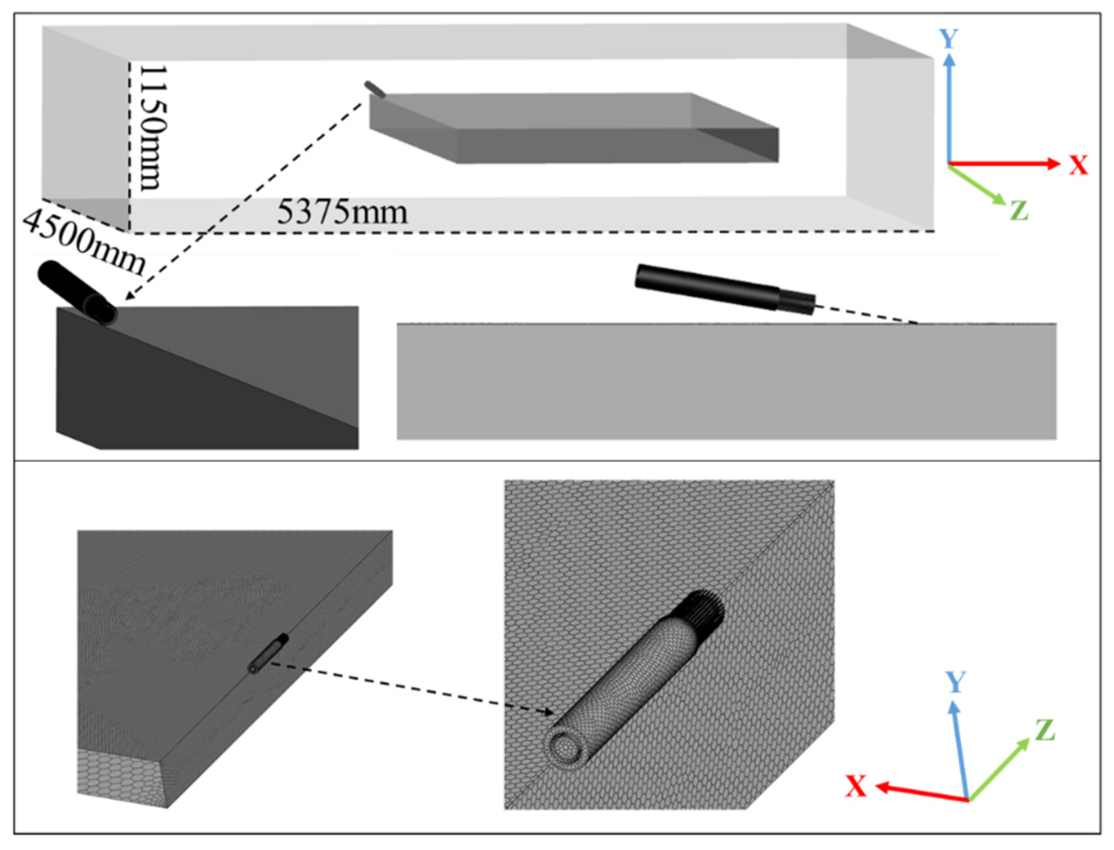
2.1. Geometric Description and Meshing

The computation domain of corner cleaning consists of the cleaning nozzle, free jet zone, and slab. Figure 1 shows the three-dimensional geometrical model and three-dimensional grid model. The free jet region has a volume of 4500 mm × 5375 mm × 1150 mm (i.e., length × width × height), and the casting slab has a volume of 4500 mm × 2150 mm × 230 mm. The corner cleaning nozzle is at an angle of 13.5° from the casting slab. The diameter of the natural gas nozzle is 1.5 mm, and the diameter of the oxygen nozzle is 30 mm. Natural gas and oxygen entered the free jet region for combustion separately. Fluent Meshing was used to carry out polyhedral mesh division for the whole computational domain. The grid encryption was carried out for the upper and right surfaces of the casting slab and the corner cleaning nozzle to improve the calculation accuracy.

2.2. Mathematical Model

In this chapter, the flow and heat transfer characteristics near the corner of the casting slab are studied. The flow is mainly affected by gas dynamics rather than combustion dynamics [31,32,33]. Therefore, the influence of the slab melting process on the flow is not considered, and the complex chemical reaction during the combustion process is simplified into a single-step reaction. The corner cleaning process can be approximated as steady-state, turbulent, and incompressible flow, which requires solving continuity equation and momentum equation.

2.2.1. Governing Equations

Continuity equation:
ρ t + x j ( ρ u j ) = 0
Momentum conservation equation:
t ( ρ u i ) + x j ( ρ u i u j ) = x j ( μ u i x j ρ u i u j ¯ ) P x i + x j [ μ ( μ j x i 2 3 μ i x j δ i j ) ]
where i = 1, 2, 3; ρ u i u j ¯ is the Reynolds stress,
ρ u i u j ¯ = μ ( u i x j + μ j x i ) 2 3 ρ κ δ i j
where u i is the turbulent viscosity, kg⋅s⋅m−2; κ is turbulent kinetic energy, m2/s2.
Energy equation:
t ( ρ E ) + x i [ μ i ( ρ E + P ) ] = x j [ ( k + C μ t P r l ) T x j + μ i ( τ i j ) e f f ]
where E is the total energy and ( τ i j ) e f f is the deviatoric stress tensor defined as:
( τ i j ) e f f = μ e f f ( u j x i + u i x j ) 2 3 μ e f f u i x j δ i j

2.2.2. Turbulence Model

The Realizable k-ε turbulence model is suitable for simulating jet flow problems. The modeled transport equations for k and ε in the realizable k-ε model are:
t ( ρ k ) + x j ( ρ k u j ) = x j [ ( μ + μ t σ k ) k x j ] + G k + G b ρ ε
t ( ρ ε ) + x j ( ρ ε u j ) = x j [ ( μ + μ t σ ε ) ε x j ] + ρ C 1 S ε ρ C 2 ε 2 k + v ε + C 1 ε ε k C 3 ε G b
G k is the generation of turbulence kinetic energy due to the mean velocity gradients. G b is the generation of turbulence kinetic energy due to buoyancy. For the Realizable k-ε model, the default energy turbulent Prandtl number P r t   = 0.85. σ k and σ ε are the turbulent Prandtl numbers for k and ε, respectively. C 1 ε = 1.44 ,   C 2 = 1.9 ,   σ k = 1.0 ,   σ ε = 1.2 .

2.2.3. Combustion Model

For mixed-is-burned approximation, Fluent provides a turbulence–chemistry interaction model, based on the work of Magnussen and Hjertager [11], called the eddy-dissipation model. With this model, the net rate of production of species i due to reaction r , R i , r , is given by the smaller (that is, limiting value) of the two expressions below:
R i , r = v i , r M w , i A ρ ε k min ( Y v , r M w , )
R i , r = v i , r M w , i A B ρ ε k P Y P j N v j , r M w , j
where: Y P is the mass fraction of any product species, P ; Y is the mass fraction of a particular reactant, ; A = 4.0, B = 0.5.

2.3. Boundary Conditions and Numerical Solution

The velocity inlet boundary conditions are adopted for natural gas and oxygen. The pressure outlet boundary conditions are adopted for the air domain exits, the backflow gas is air, the rest are the stationary walls, and the standard wall function is adopted for the near-wall area. Four surfaces of the casting slab were selected for convection boundary conditions, the upper and right surfaces’ heat transfer coefficient is 100 (W/m2∙K), and the under and left surfaces’ heat transfer coefficient is 10 (W/m2∙K). A pressure-based solver is adopted, and the SIMPLE algorithm is employed for pressure–velocity coupling. Under-relaxation factors of density and momentum are appropriately adjusted. The convergence criteria for energy and p-1 are 10−6, while the other convergence criteria are 10−4.

2.4. Flame Corner Cleaning Results and Discussion

Some sections are made in each direction of the computation domain to intuitively display the flame jet, as shown in Figure 2. Along the Z-axis (the slab casting direction), Section 1 (Z = 1.2 m) is the first plane, Section 11 (Z = 3.2 m) is the last plane, and the space of each section is 0.2 m. There are nine sections between Section 1 and Section 11. The blue sections are the upper and right surfaces of the casting slab, the black section is the 45° section of the nozzle center, the red part is the cleaning nozzle, and the orange dotted border is the computational domain. It is convenient to analyze the primary flame jet distribution at the corner of the casting slab from these sections.

2.4.1. Grid Independence Validation

In order to estimate the independence of the grid, three polyhedral grid schemes of 992441, 1202513, and 1333694 are selected for simulation. As shown in the three black dotted lines in Figure 2, the velocity of three lines at Z = 1.2 m, 1.8 m, and 2.4 m on the casting slab’s upper surface of three grids was extracted for comparison. As shown in Figure 3, the calculation results show that the maximum speeds of the three grids are 91.78 m/s, 93.21 m/s, and 92.78 m/s, respectively. The velocity difference between the three grids is very small and can be ignored, and the simulation results are independent of the grid size. Thus, the scheme of 1202513 is applied in the present study. The calculation process stability and results accuracy reached the requirements.

2.4.2. Validation of Numerical Simulation

The predictions of the flame jet distribution are validated by comparing with the practical factory tests, as shown in Figure 4. The red part is the cleaning nozzle, the zone between Line 1 and Line 2 is the gas jet area, and the zone behind Line 2 is the gas dispersion area. It can be clearly seen that the flame is divided into two streams after reaching the corner of the casting slab and gradually spreads out.
The key to corner flame cleaning is the nozzle. The flame shape and temperature distribution at the nozzle outlet are important indexes to measure the simulation results. It can be seen from Figure 5a that the flame color at the nozzle outlet is white-blue, and the temperature of the white-blue flame is generally above 1500 °C. The oxygen concentration is 99.6%, and the fuel is natural gas, in which the methane concentration is 95%. Under this condition, the highest combustion temperature of natural gas can reach 3400 °C, which fully satisfies the cutting standard of industrial gas. Numerical simulation results show that the temperature at the nozzle outlet is above 1500 °C, and the highest temperature is 2924 °C. As shown in Figure 5b, the flame jet is all concentrated together and converges at the corner part of the casting slab. The corner cleaning is realized, and the cleaning quality is stable. The factory results agreed well with the simulation results.
During the actual production process, oxygen concentration, pressure, and velocity distribution are most noteworthy. As shown in Figure 6a, when the oxygen jet impinges on the casting slab corner, uniformly separates into two jet streams, and along the surface of the casting slab spreading, concentration gradually reduces. The oxygen concentration at the impinge region is above 90%, higher than in other areas, which is helpful for the iron oxide reaction. As shown in Figure 6b, at the impinge region of the gas stream, the velocity exceeded 90 m/s. When the gas reached the free flow space, the velocity decreased to 10 m/s around, and the flow entered a full development state. High-speed gas flow can continuously push the molten pool forward to ensure the reaction stability and blow away the slag to avoid the slag accumulation in the corner and affect the cleaning effect. Figure 6c shows the contour map of pressure on the casting slab’s upper and right surfaces. It can be seen that the main action range of the gas jet is conical. After the gas reached the corner impinge region, the gas gradually diffused, and the action range gradually increased, conducive to the corner cleaning of the casting slab. The pressure is large in the main jet area of the high-speed gas, and the flow rate is fast, which conforms to production expectations in Figure 6d. Due to the special design of the nozzle, oxygen is restricted without divergence. High-concentration oxygen impinges on the casting slab corner are presented in Figure 6e, which is conducive to iron oxidation reaction. As shown in Figure 6f, the velocity at the oxygen outlet exceeds 120 m/s, and the highest speed is 148 m/s. The constraint of the gas flow is good, and oxygen is not extensive diffusion to ensure the molten pool push force.

2.4.3. Effect of Different Oxygen Flow Rates on Velocity and Oxygen Concentration Distribution

In the actual working process of the factory, the oxygen flow rate range is 400–800 m3/h. The range is determined according to the combustion reaction rate and the amount of metal removal. Too low a flow rate leads to insufficient oxygen involved in the chemical reaction, and too high a flow rate leads to waste of oxygen. Figure 7 shows the velocity distribution at the edge of the slab under five oxygen flow rates, and the edge is the red line segment shown in Figure 2. With the oxygen flow rate decreasing from 800 m3/h to 400 m3/h, the velocity at the edge decreases. At the same time, the force pushing the molten pool forward also decreases. It can be seen from the X-coordinate direction that the range of the main action of the gas is roughly from 1.08 m to 1.80 m. The maximum velocity corresponding to the five flow rates has been marked in the figure, and the impact point is at 1.19 m.
During the process of corner flame cleaning, a large amount of high-purity oxygen is needed. The higher the oxygen concentration, the more conducive to iron oxide reaction, removing corner defects. As shown in Figure 8, when the oxygen flow rate is 400 m3/h, oxygen concentration over 90% of areas is roughly distributed in a rectangle with a length of 219.0 mm and width of 31.4 mm. With the increase in oxygen flow rate, the area of high oxygen concentration gradually decreases. If iron is not completely oxidized and slag is formed to stick to the corner of the casting slab, the cleaning effect will be affected. Therefore, it is of great significance to find the appropriate oxygen flow rate according to the actual production.

2.4.4. Effect of Different Nozzle Angles

Figure 9 shows the relative position of the nozzle and the corner edge. With the angle between the nozzle and the slab corner changing, the gas’s action range and impact velocity also changed. The greater the angle between the nozzle and the corner edge, the smaller the action range of the gas, and the greater the impact velocity. As shown in Figure 10, when the angle is 12°, 13.5°, and 15°, respectively, the maximum speeds are 88.03 m/s, 93.54 m/s, and 94.20 m/s, respectively. With the increase in angle, the action areas of velocity greater than 10 m/s become smaller, which are 0.86 m, 0.72 m, and 0.64 m, respectively. The angle range is considered the actual equipment production, and installation process, facilitating the mutual cooperation between the various components.
The nozzle angle will affect the corner cleaning depth. Figure 9 shows the distribution of oxygen concentration in the corner. It can be seen that the change of angle has a significant influence on the distribution of oxygen concentration. At 15°, oxygen concentration over 90% of areas is roughly distributed in a rectangle with a length of 86.9 mm and width of 9.2 mm, when at 13.5°, they are 64.9 mm and 6.4 mm, no more than 90% of the region at 12°. Therefore, when the scarfing machine works, it is necessary to consider the flow rate and angle to cooperate with each other and save resources under the premise of ensuring the production quality.

3. Model Establishment and Results Analysis of Corner Molten Pool

The steel in the corner of the slab is heated locally via a high-temperature flame obtained from natural gas and oxygen combustion. When reaching the ignition point, the steel is melted by a jet creating a continuous chemical reaction between the iron and the oxygen. The slag is blown away by the gas jet. The flame cleaning process reaction is complex, and it is difficult to simulate the formation and blown away of slag. The suitable method is to set a total heat source, which can effectively simulate the temperature field of the slab, although it cannot simulate the actual slag situation [27,34,35]. When simulating the formation of the molten pool in flame cleaning, the fluid flow is generally ignored and only considers the effect of flame and iron oxidation reaction heat on the molten pool. It is important to point out that to simulate the phenomenon of slag blown away after cleaning the corner, the thermal conductivity of the part blown away changed to air and removed the heat amount of slag blown away. Another advantage of this method is that the liquid zone can avoid acting as an additional heat source to heat the casting slab.

3.1. Mathematical Model and Numerical Solution

Based on the above research and assumptions, as shown in Figure 11, the 2D elliptic heat source model is used to simulate the jet flame heating of the casting slab. The 3D Gauss heat source model of revolution is used to simulate the exothermic heat of the iron oxide reaction.
The 2D elliptic heat source model distribution function is:
q ( x , y ) = 3 Q π a b exp ( 3 x 2 a 2 3 y 2 b 2 )
where: x and y are the center of the heat source horizontal and vertical coordinates, respectively; Q is heat input rate, w; a is the elliptical short axis, m; b is the elliptical long axis, m.
The 3D Gauss heat source model of the revolution distribution function is:
q ( x , y , z ) = 3 C s Q π H ( 1 1 e 3 ) exp [ 3 C s log ( H z ) ( x 2 + y 2 ) ]
C s = 3 R 0 2
where: H is heat source height, m; Q is heat input rate, w; R 0 is heat source radius, m; C s is coefficient of heat concentration, 1/m2.
For solidification/melting problems, the energy equation is written as
t ( ρ H ) + ( ρ v H ) = ( k T ) + S
where: H is enthalpy, J/kg; ρ is density, kg/m3; v is the fluid velocity, m/s; S is the source term, W/m3.
The calculation domain is 4500 mm × 2150 mm × 230 mm. The grid encryption area is the main UDF function area. The size of encryption is 3 mm to improve the calculation accuracy. The number of mesh is about 1.73 million. In the cleaning process of the slab corner, as shown in Figure 12, the flame cleaning process can be divided into three parts: the yellow part has been cleaned, the green part is being cleaned, and the blue part will be cleaned. During the cleaning process, the heat sources consist of flame heating on the upper and right surfaces of the slab and iron oxidation reaction heating on the molten pool.
The material used in this paper is low carbon steel, and thermal physical properties are shown in Table 1.
In the 3D model of the casting slab, the radiative and convective boundary conditions were selected for the upper and right surfaces, and the 2D elliptic heat source model was loaded on both sides, a combined heat transfer coefficient was calculated from the relationship [38]: H = 24.1 × 10⁻⁴ × ε × T1.61. Where ε is the emissivity or degree of blackness of the surface of the body. ε is assumed to be equal to 0.9. The other four surfaces of the casting slab were selected for convection boundary conditions, and the heat transfer coefficient is 10 (W/m2∙K). The 3D gauss heat source model of revolution is added to the energy source term in the computational domain. A pressure-based solver and the SIMPLE algorithm are employed for pressure-velocity coupling. The constant time step size is 0.01 s. The convergence criteria for energy and p-1 are 10−6, while the other convergence criteria are 10−3.

3.2. Results of Molten Pool Formation and Discussion

As shown in Figure 13, the red part exceeding 1797 K is mainly due to the iron oxidation reaction simulated by the 3D gauss heat source model. The front two elliptic parts are due to the effect of the flame heating on the upper and right surfaces of the slab simulated by the 2D elliptic heat source model. The cleaned slab moves forward at the speed of 0.05 m/s, and the corner molten pool forms and becomes larger and larger. At 10 s and 20 s, it can be seen that the temperature of the molten pool is higher than the tail part because the corner slag formed by the iron oxidation reaction is blown away by the high rate flame jet, and a large amount of heat is taken away.
The shape of the corner molten pool can be better understood by observing the front of the flame jet impinging zone. Figure 14 presents the three-dimensional views of the molten pool front part at the 20 s, that is, the area where the iron oxide reaction occurs. In the front view, the red area is the part that exceeds the melting point of low carbon steel, the length of the black lines are 58.1 mm and 57.9 mm on both sides, and the corner melting depth is 29.9 mm. Figure 15 is the corner depth diagram after corner cleaning in the factory. The factory results are 58.0 mm and 56.9 mm on both sides, and the corner melting depth is 21.4 mm, the error is 7.04%. The molten pool shape is observed from four perspectives for easy understanding, as shown in Figure 16. From the global view, it can be seen that the overall shape of the molten pool, the head is relatively sharp, and then it transitions smoothly and gradually widens. From the front view, it can be seen that the casting slab corner molten pool is smooth and circular. The shape of the top view is the same as the right view. The simulation results agreed well with the factory results. Thus, it is demonstrated that these two heat source models are suitable for simulating and studying the formation of the molten pool during the corner flame cleaning process. It is helpful for reducing the number of trial-and-error experiments.

4. Conclusions

  • The complicated transport characteristics in the corner flame cleaning process are investigated using a numerical simulation method based on the experiment from the practical process. For simplicity, the cleaning process can be divided into two parts (cleaning flame jet zone and molten pool zone) to simulate separately. These results are helpful for clearly understanding the actual cleaning process and improving the process parameters;
  • A three-dimensional fully coupled model for the flame cleaning nozzle is developed to simulate the flow pattern of the flame jet, Oxygen concentration distribution, and temperature field in the corner of the slab. The simulated flame jet flow field and temperature results agreed well with the factory trial results;
  • With the increase in oxygen flow rate, the velocity at the corner also increases, and the area of high oxygen concentration gradually decreases. The corner cleaning depth can be controlled by the oxygen flow rate to improve the slab quality and improve the metal recovery rate. The greater the angle of nozzle and slab, the smaller the action range of the gas, and the greater the impact velocity. With the increase in the angle, the area of high oxygen concentration gradually increases. Therefore, choosing the suitable flow rate and the angle parameters is necessary to save resources and ensure product quality;
  • A three-dimensional thermal model for simulation of the molten pool formed by flame cleaning in the corner of the casting slab has also been developed. The predicted results of the molten pool shape agreed well with the results from the industry trials. The present study has demonstrated that these two heat source models are suitable for simulating and studying the formation of the molten pool during the corner flame cleaning process.

Author Contributions

Conceptualization, C.W., Y.Z. and J.Z.; Data curation, C.W.; Formal analysis, C.W.; Funding acquisition, B.W.; Investigation, C.W., J.Z. and B.W.; Methodology, C.W. and B.W.; Project administration, B.W.; Resources, C.W., J.Z. and B.W.; Supervision, B.W.; Validation, C.W. and A.G.; Writing—original draft, C.W.; Writing—review and editing, C.W. and B.W. All authors have read and agreed to the published version of the manuscript.

Funding

The authors gratefully express their appreciation to the Innovation Program of the Shanghai Municipal Education Commission (NO. 2019-01-07-00-09-E00024). This work was supported by Independent Research and Development Project of State Key Laboratory of Advanced Special Steel, Shanghai Key Laboratory of Advanced Ferrometallurgy, Shanghai University (SKLASS 2021-Z02) and the Science and Technology Commission of Shanghai Municipality (No. 19DZ2270200, 20511107700).

Institutional Review Board Statement

Not applicable.

Informed Consent Statement

Not applicable.

Data Availability Statement

Not applicable.

Conflicts of Interest

The authors declare no conflict of interest.

References

  1. Li, Y.M.; Li, B.K.; Qi, F.S. Non-premixed Combustion of Parallel Multiple Jets in Scarfing Process. J. Northeast. Univ. (Nat. Sci.) 2019, 40, 505–509. [Google Scholar]
  2. Qi, F.S.; Chen, J.J.; Li, Y.M.; Li, B.K. Numerical Study on Mixing Characteristic of Jet Flow from Packed Holes Based on Automatic Scarfing Machine. China Metall. 2014, 24, 158–162. [Google Scholar]
  3. Chen, J.; Li, B.K.; Qi, F.S. Effect of multi-jet merging on the slab surface quality in the scarfing process Compressible fluidity of gas. Heavy Mach. 2018, 4, 52–57. [Google Scholar]
  4. Li, Y.M.; Li, B.K.; Qi, F.S.; Sherman, C.P. Flow and heat transfer of parallel multiple jets obliquely impinging on a flat surface. Appl. Therm. Eng. 2018, 133, 588–603. [Google Scholar] [CrossRef]
  5. Li, Y.M.; Li, B.K.; Qi, F.S.; Wang, X.C. Numerical investigation of the interaction of the turbulent dual-jet and acoustic propagation. Chin. Phys. B 2017, 26, 024701. [Google Scholar] [CrossRef]
  6. Egon, E. Impulse torch for energy-saving slab scarfing. Metall. Plant Technol. Int. 2007, 30, 50–53. [Google Scholar]
  7. Tomohide, T.; Masanori, K.; Katsuya, T. Improvement of bloom surface quality in the hot scarfing process. Res. Dev. Kobe Steel Eng. Rep. 2011, 61, 24–28. [Google Scholar]
  8. Showalter, M.S.; Nemchinsky, V.A.; Khan, J.A. Fundamental study of oxygen scarfing process. Am. Soc. Mech. Eng. 1996, 323, 233–238. [Google Scholar]
  9. Frank, J.H.; Barlow, R.S.; Lundquist, C. Radiation and nitric oxide formation in turbulent non-premixed jet flames. Proc. Combust. Inst. 2000, 28, 447–454. [Google Scholar] [CrossRef]
  10. Paul, S.C.; Paul, M.C.; Jones, W.P. Large eddy simulation of a turbulent non-premixed propane-air reacting flame in a cylindrical combustor. Comput. Fluids 2010, 39, 1832–1847. [Google Scholar] [CrossRef] [Green Version]
  11. Yan, Y.Y.; Zhang, Y.; Yang, F. Combustion heat transfer numerical simulation for reactor based on ANSYS CFX. J. Shaanxi Univ. Sci. Technol. 2013, 31, 134–138. [Google Scholar]
  12. Chen, Z.Y.; Wang, J.B.; Tian, Y. Numerical simulation of scarfing machine burners flame characteristics. Iron Steel 2016, 51, 87–92. [Google Scholar]
  13. Choi, D.C.; Jeon, Y.J.; Kim, S.W. Faulty scarfing slab detection using machine vision. Adv. Mater. Res. 2012, 462, 185–190. [Google Scholar] [CrossRef]
  14. Faghani, E.; Rogak, S.N. A phenomenological model of two circular turbulent jets. Int. J. Eng. Res. 2013, 14, 293–304. [Google Scholar] [CrossRef]
  15. Wang, J.Y.; Priestman, G.H.; Wu, D.D. An analytical solution for incompressible flow through parallel multiple jets. J. Fluids Eng. 2001, 123, 407–410. [Google Scholar] [CrossRef]
  16. Kuepper, H.; Schaub, E. Oxygen Cutting and Flame Scarfing in an Open Die Forge. Stahl Eisen 1972, 92, 1098–1105. [Google Scholar]
  17. Daiker, A.L. Continuous and sampled scarfing of stainless steel. Metallurgist 1974, 18, 451–453. [Google Scholar] [CrossRef]
  18. Pfeuffer, A. Development of scarfing equipment. Iron Steel Int. 1975, 48, 147–151. [Google Scholar]
  19. Sancho, L.F.; Samoano, J.R.; Alvarez, I. Automated on-line inspection of surface scarfing in slabs and quality assessment based on novel image technologies. Rev. Metall. 2008, 105, 383–389. [Google Scholar] [CrossRef]
  20. Han, J.; Chen, T. Application of Scarfing Machine in Slab Continue Casting Production. Contin. Cast. 2012, 2, 38–41. [Google Scholar]
  21. Zhang, C.Y.; Song, H.; Wang, Y.S.; Li, Q. Application and reformation of continuous casting slab scarfing gun. Sci. Technol. Baotou Steel (Group) Corp. 2001, 27, 72–74. [Google Scholar]
  22. Zhang, J.; Wang, G.; Fan, H.N.; Zhang, L.X.; Zhou, Y.H.; Wang, Q. Production Practice of Ma Steel Slab Scarfing Machine. Contin. Cast. 2018, 43, 38–41. [Google Scholar]
  23. Qin, Z.M. Practical analysis of scarfing machine in slab continuous casting production at Baosteel. Baosteel Technol. 2020, 1, 64–68. [Google Scholar]
  24. Jokiaho, T.; Santa-aho, S.; Peura, P.; Vippola, M. Role of Steel Plate Thickness on the Residual Stress Formation and Cracking Behavior during Flame Cutting. Metall. Mater. Trans. A 2019, 50, 4178–4192. [Google Scholar] [CrossRef] [Green Version]
  25. Jokiaho, T.; Santa-aho, S.; Peura, P.; Vippola, M. Cracking and Failure Characteristics of Flame Cut Thick Steel Plates. Metall. Mater. Trans. A 2020, 51, 1744–1754. [Google Scholar] [CrossRef] [Green Version]
  26. Liang, G.F. Cutting Technical Manual; China Machine Press: Beijing, China, 2017. [Google Scholar]
  27. Thiébaud, R.; Drezet, J.M.; Lebet, J.P. Experimental and numerical characterisation of heat flow during flame cutting of thick steel plates. J. Mater. Process. Technol. 2014, 214, 304–310. [Google Scholar] [CrossRef] [Green Version]
  28. Arenas, M.J.; Hömberg, D.; Lasarzik, R.; Mikkonen, P.; Petzold, T. Modelling and simulation of flame cutting for steel plates with solid phases and melting. J. Math. Ind. 2020, 10, 304–310. [Google Scholar] [CrossRef]
  29. Zhang, S.Y.; Tang, X.H.; Lai, M.J.; He, J. Numerical Simulation Analysis of Gas Flame Cutting Steel Plate Temperature Field. Weld. Technol. 2013, 42, 10–13. [Google Scholar]
  30. Yu, J.; Wang, S.H.; Wang, G.C.; Huang, X.; Song, K.; Lu, S.Q.; Ding, J. Analysis on Heat and Mass Transfer During Hydrogen Absorption in ZrCo Hydride Beds Based on UDF Heat Source Model. J. Chongqing Univ. Technol. (Nat. Sci.) 2021, 35, 234–242. [Google Scholar]
  31. Martinez, D.M.; Jiang, X. Numerical investigations of a hydrogen impinging flame with different finite-rate chemical kinetic mechanisms. Fuel 2013, 109, 285–296. [Google Scholar] [CrossRef]
  32. Hindasageri, V.; Vedula, R.P.; Prabhu, S.V. Heat transfer distribution for impinging methane-air premixed flame jets. Appl. Therm. Eng. 2014, 73, 461–473. [Google Scholar] [CrossRef]
  33. Tajik, A.R.; Kuntikana, P.; Prabhu, S.V.; Hindasageri, V. Effect of preheated mixture on heat transfer characteristics of impinging methane-air premixed flame jet. Int. J. Heat Mass Transf. 2015, 86, 550–562. [Google Scholar] [CrossRef]
  34. Liu, P.X.; Zhang, Y.S.; Liu, H.Q.; Gui, Z.X. Modeling for periodic striation and microstructure evolution in active gas melt laser cutting for phase hardened parts. Int. J. Adv. Manuf. Technol. 2014, 70, 1421–1426. [Google Scholar] [CrossRef]
  35. Nyon, K.Y.; Nyeoh, C.Y.; Mokhtar, M.; Razi, A.R. Finite element analysis of laser inert gas cutting on Inconel 718. Int. J. Adv. Manuf. Technol. 2012, 60, 995–1007. [Google Scholar] [CrossRef]
  36. Li, H.; Wang, Y.F.; Shi, Z.Q.; Sun, X.; Xiao, Y.M.; Wang, T. Simulation of Laser Cladding Temperature Field and Flow Field Based on Ellipse Heat Source Model. Appl. Laser 2017, 37, 218–222. [Google Scholar]
  37. Liu, X.Z.; Liu, L.J. Influence of Different Body Heat Source Models on Welding Temperature Field of T-joint. Agric. Equip. Veh. Eng. 2021, 59, 55–59. [Google Scholar]
  38. Goldak, J.; Chakravarti, A.; Bibby, M. A New Finite Element Model for Welding Heat Sources. Metall. Trans. B 1984, 15, 299–305. [Google Scholar] [CrossRef]
Figure 1. Three-dimensional geometrical model and three-dimensional grid model.
Processes 10 00798 g001
Figure 2. Schematic diagram of different sections.
Processes 10 00798 g002
Figure 3. Effect of grid number on the impinged surface velocity.
Processes 10 00798 g003
Figure 4. Working condition of corner cleaning of casting slab in factory and velocity vector on the upper and right surfaces of casting slab.
Processes 10 00798 g004
Figure 5. (a) Corner cleaning flame shape in factory; (b) The flame shape and temperature at the nozzle outlet.
Processes 10 00798 g005
Figure 6. (a) O2 concentration distribution on the upper and right surfaces of casting slab; (b) velocity on the upper and right surfaces of casting slab; (c) pressure on the upper and right surfaces of casting slab; (d) pressure at 45° section of nozzle center; (e) O2 concentration distribution at 45° section of nozzle center; (f) velocity at 45° section of nozzle center.
Processes 10 00798 g006
Figure 7. Velocity of the casting slab surface under different oxygen flow rates.
Processes 10 00798 g007
Figure 8. Oxygen concentration distribution of the casting slab surface.
Processes 10 00798 g008
Figure 9. Oxygen concentration distribution of the casting slab surface.
Processes 10 00798 g009
Figure 10. Velocity of the casting slab surface under different angles.
Processes 10 00798 g010
Figure 11. The 2D elliptic heat source model [36] and 3D Gauss heat source model of revolution [37].
Processes 10 00798 g011
Figure 12. Schematic diagram of oxygen-natural gas flame cutting process.
Processes 10 00798 g012
Figure 13. Temperature diagram of the upper and right surfaces of casting slab at different times.
Processes 10 00798 g013
Figure 14. Three views of the front of the molten pool at 20 s.
Processes 10 00798 g014
Figure 15. Corner depth diagram after corner cleaning in the factory.
Processes 10 00798 g015
Figure 16. ISO-surface of 1797 K temperature at 20 s.
Processes 10 00798 g016
Table 1. Thermal physical properties of low carbon steel.
Type of SteelLow Carbon Steel
Liquidus temperature/(K)1797
Solidus temperature/(K)1768
Latent heat/(J/kg)270,000
Specific heat/(J/(kg·K)680
Solidus density/(kg/m3)7200
Solidus viscosity/(Pa·s)6.2
Solidus thermal conductivity/(W/(m·K))28.4
Publisher’s Note: MDPI stays neutral with regard to jurisdictional claims in published maps and institutional affiliations.

