
Coal Pillar Stress Weakening Technology and Application by Gob-Side Entry Driving and Hydraulic Roof Cutting in Deep Shafts Mines

 ,
,
Abstract
:1. Introduction
2. Project Overview
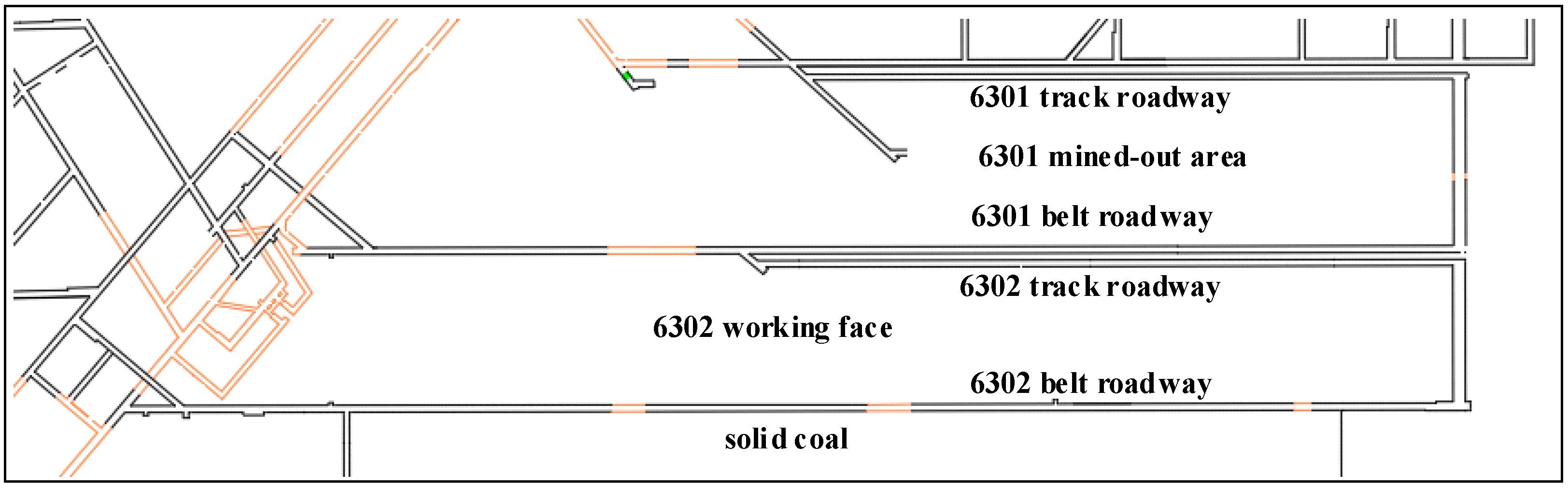
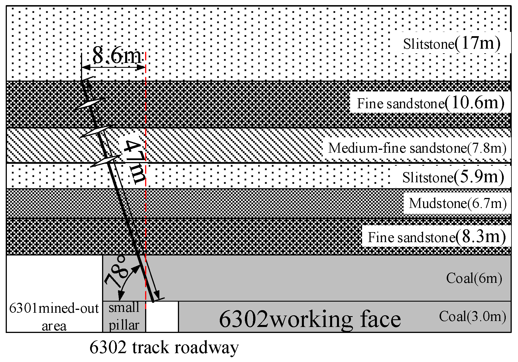
2.1. Project Geological Conditions
2.2. Field Measurements of the Entry Deformation Failure of 6302 Track
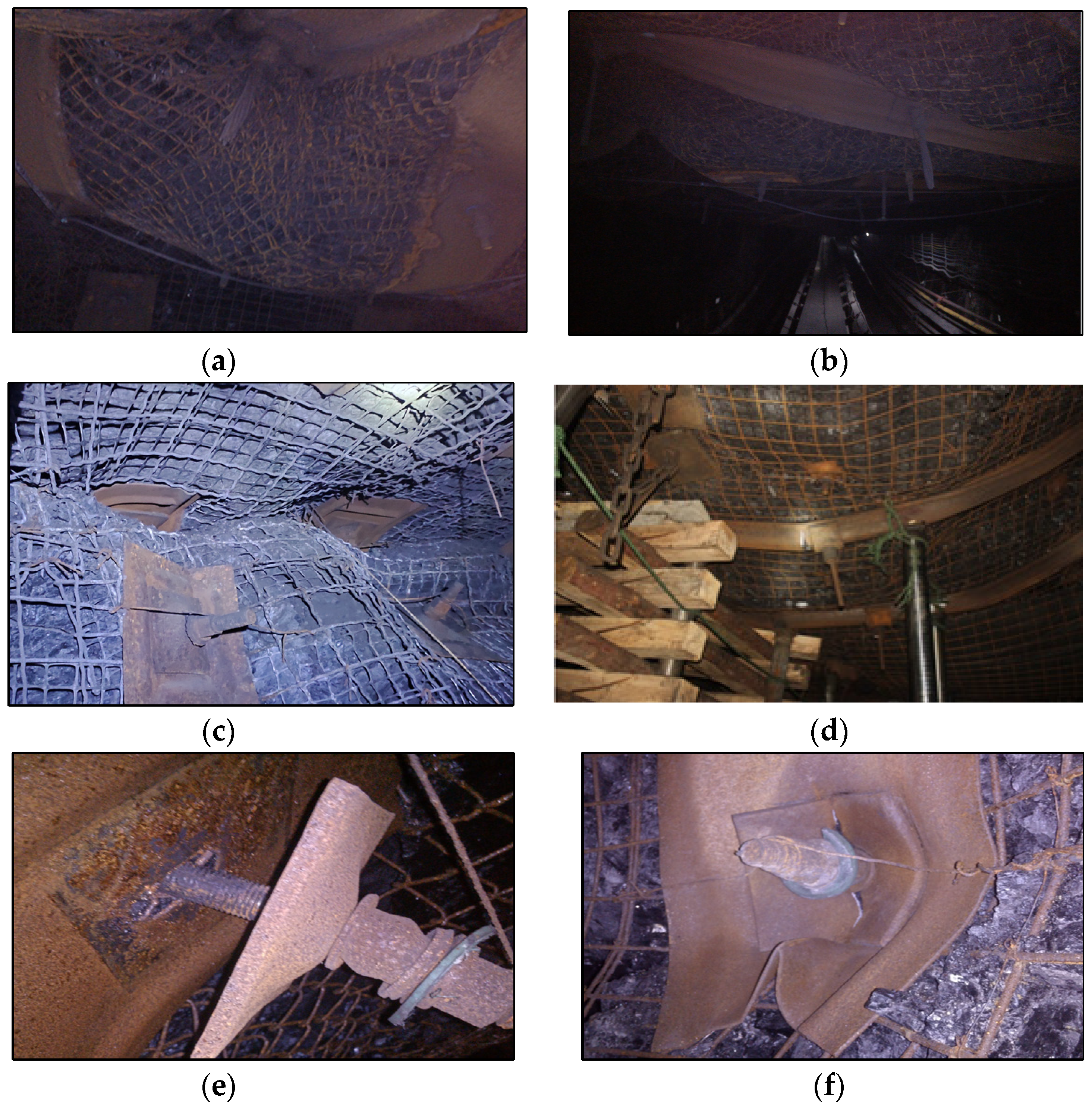
- (1)
- Roof bulging. The surrounding rock of the roof and shoulder are broken, and “net pockets” appear, accompanied by sinking of the roof (Figure 2a,b).
- (2)
- Buttock shear slip. It mainly occurs at the coal pillar–coal–rock junction, where the buttock is squeezed inward and the shoulder experiences shear slip (Figure 2c).
- (3)
- Sinking roof. The roof sinks significantly, the anchor bolt (rope) load increases, and the anchor net tears (Figure 2d).
- (4)
- Anchor bolt (rope) breakage. The anchor bolt (rope) in the shoulder of the coal pillar is subjected to compound stress of tension, bending, and shear, and it breaks beyond the strength limit, which is accompanied by pallet out–turning deformation (Figure 2e,f).
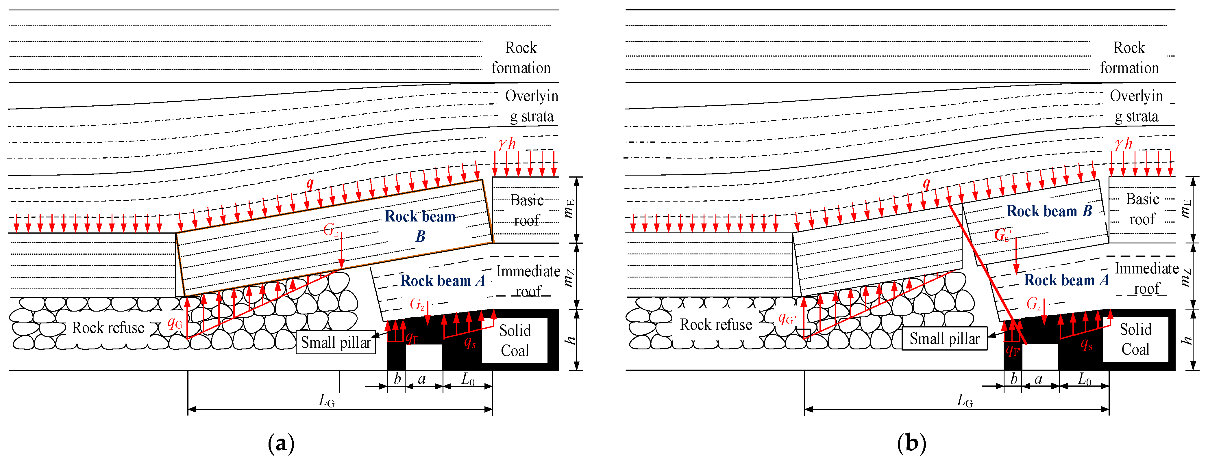
3. Analysis of the Principle of Hydraulic Fracturing Roof Cutting and Pressure Relief of Gob-Side Entry Driving
4. Analysis of the Impact of Hydraulic Fracturing Roof Cutting Pressure Relief on the Stress of the Surrounding Rocks of Gob-Side Entry Driving
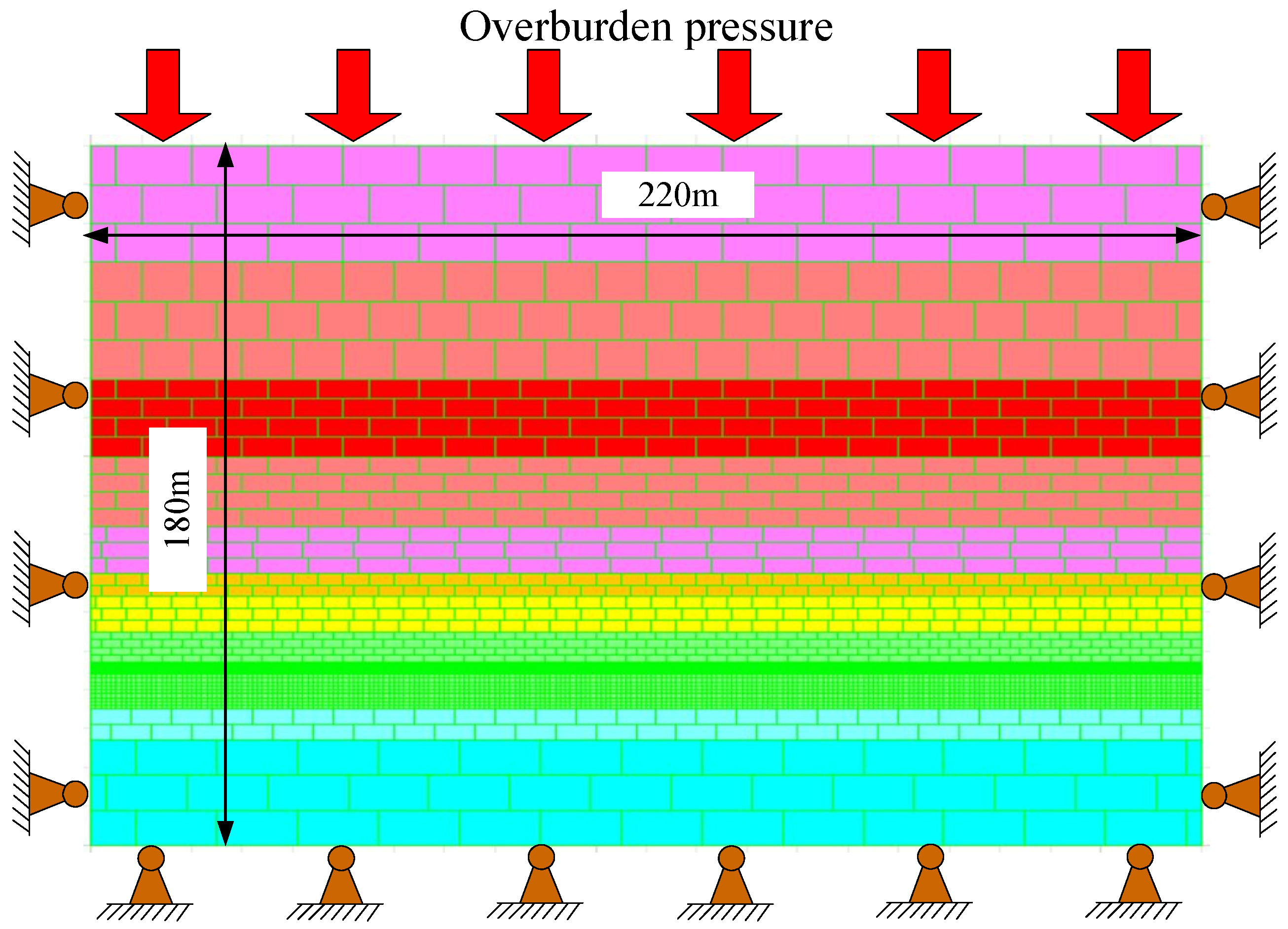
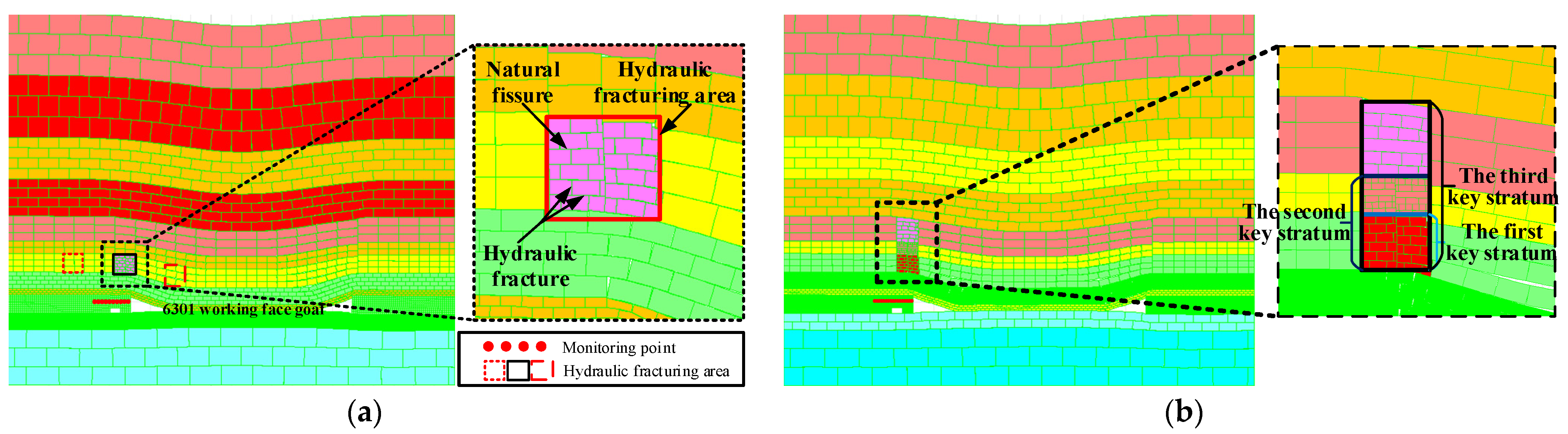
4.1. Modeling
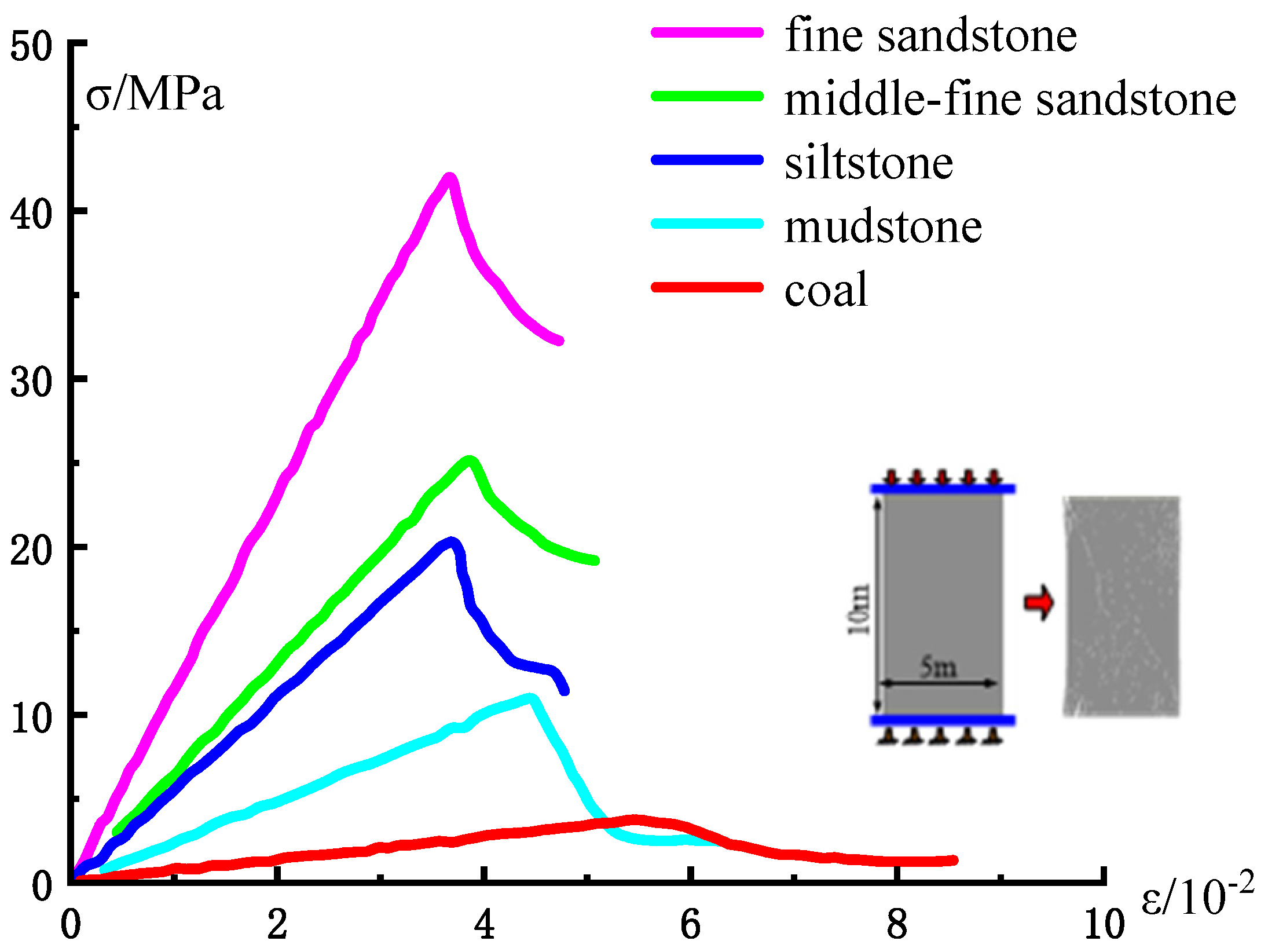
4.2. Mechanical Parameter Calibration
4.3. Numerical Simulation Scheme
4.4. Analysis of the Effect of Roof Cutting Angle on Surrounding Rock Stress
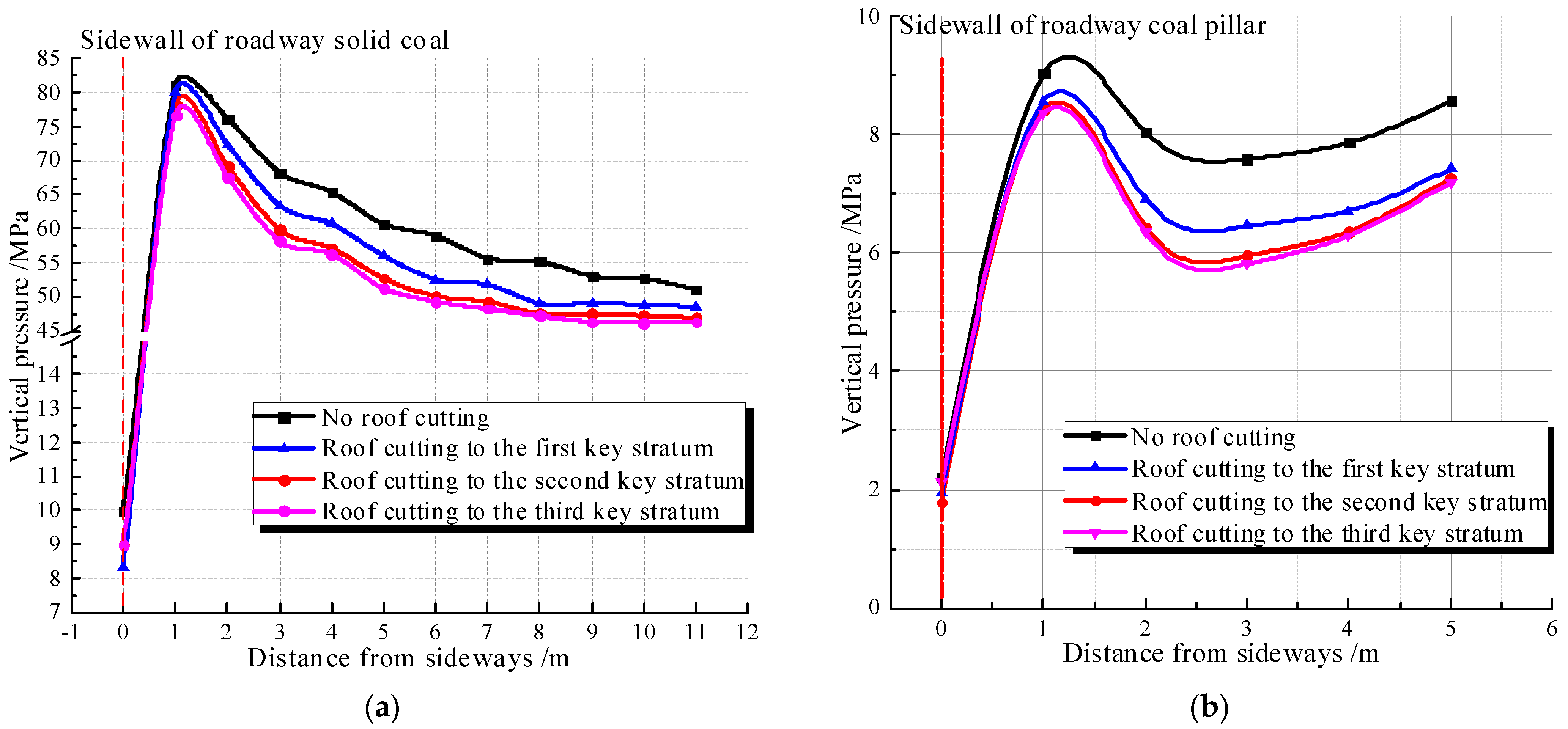
4.5. Analysis of the Effect of Roof Cutting Height (Stratahorizon) on Surrounding Rock Stress
5. Field Application and Effect test of Hydraulic Fracturing Roof Cutting of Gob-Side Entry Driving
5.1. Composition of Hydraulic Roof Cutting Equipment
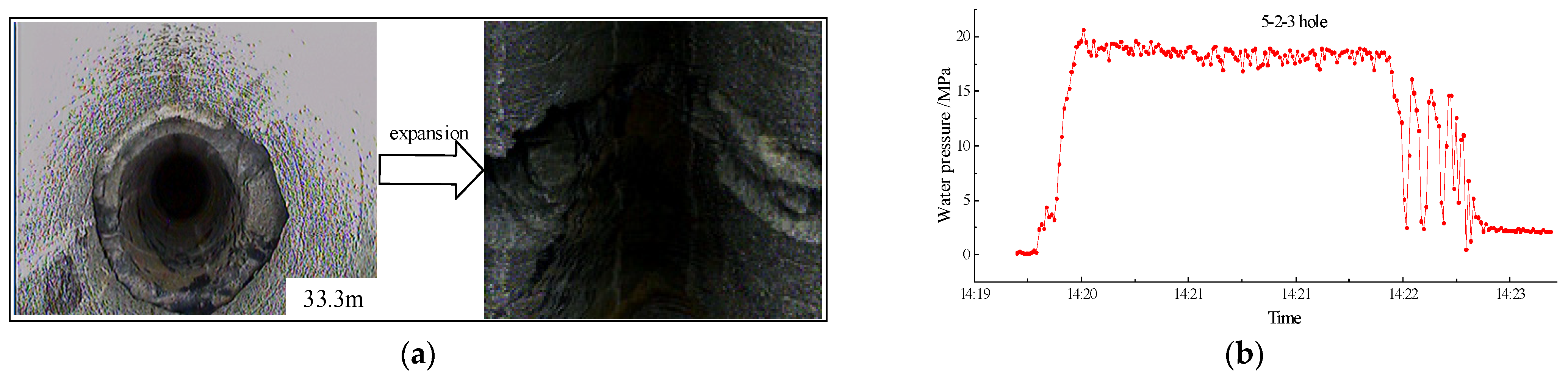
5.2. Hydraulic Cut Top Pressure Removal Site Implementation
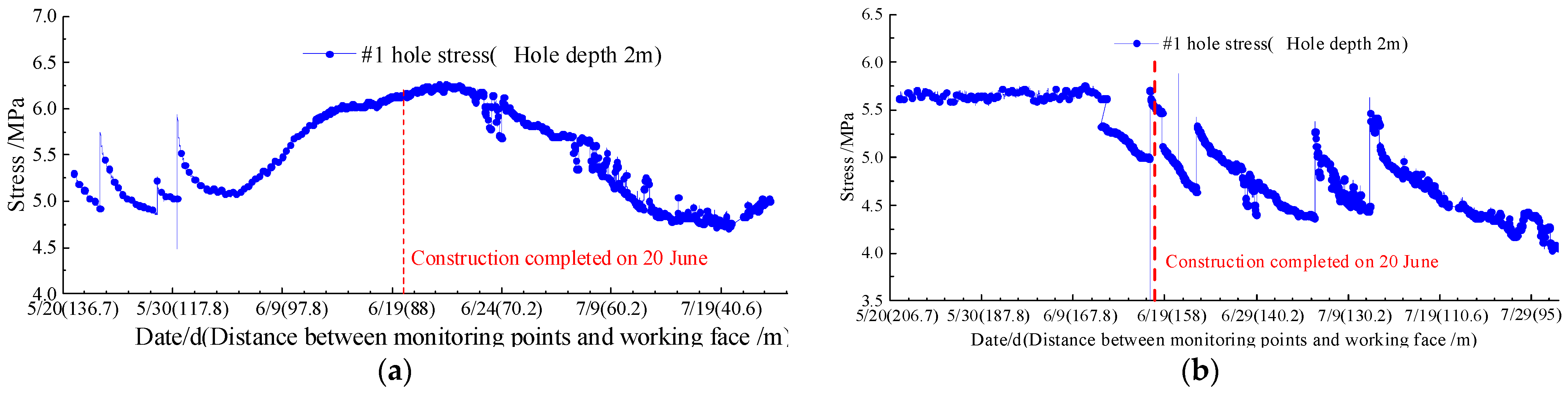
5.3. Effectiveness Test
6. Conclusions
Author Contributions
Funding
Institutional Review Board Statement
Informed Consent Statement
Data Availability Statement
Acknowledgments
Conflicts of Interest
References
- Li, X.; Zhang, N.; Xie, Z.; Liang, D.; Zhao, Y. Study on efficient utilization technology of coal pillar based on gob-side entry driving in a coal mine with great depth and high production. Sustainability 2019, 11, 1706. [Google Scholar] [CrossRef] [Green Version]
- Zhang, H.; Wan, Z.; Ma, Z.; Zhang, Y. Stability control of narrow coal pillars in gob-side entry driving for the LTCC with unstable overlying strata: A case study. Arab. J. Geosci. 2018, 11, 665. [Google Scholar] [CrossRef]
- Wang, K.; Huang, Y.; Gao, H.; Zhai, W.; Qiao, Y.; Li, J.; Ouyang, S.; Li, W. Recovery Technology of Bottom Coal in the Gob-side Entry of Thick Coal Seam Based on Floor Heave Induced by Narrow Coal Pillar. Energies 2020, 13, 3368. [Google Scholar] [CrossRef]
- Zhang, Y.; Wan, Z.; Li, F.; Zhou, C.; Zhang, B.; Guo, F.; Zhu, C. Stability of coal pillar in gob-side entry driving under unstable overlying strata and its coupling support control technique. Int. J. Min. Sci. Technol. 2013, 23, 193–199. [Google Scholar] [CrossRef]
- Chen, A. Width Design of Small Coal Pillar of Gob-side Entry Driving in Soft Rock Working Face and Its Application of Zaoquan Coal Mine. Adv. Civ. Eng. 2021, 2021, 9999957. [Google Scholar] [CrossRef]
- Feng, G.; Wang, P. Stress environment of entry driven along gob-side through numerical simulation incorporating the angle of break. Int. J. Min. Sci. Technol. 2020, 30, 189–196. [Google Scholar] [CrossRef]
- Qiu, P.; Wang, J.; Ning, J.; Shi, X.; Hu, S. Experimental investigation on bolted rock mass under static–dynamic coupled loading. Geomech. Eng. 2022, 29, 99–111. [Google Scholar]
- Cui, J. Study on deformation and failure mechanism and control technology of deeply gob-side entry driving. Coal Sci. Technol. 2017, 45, 12–17. [Google Scholar]
- Shi, X.; Jing, H.; Zhao, Z.; Gao, Y.; Zhang, Y.; Bu, R. Physical Experiment and Numerical Modeling on the Failure Mechanism of Gob-side Entry Driven in Thick Coal Seam. Energies 2020, 13, 5425. [Google Scholar] [CrossRef]
- Xiang, Z.; Zhang, N.; Xie, Z.; Guo, F.; Zhang, C. Cooperative control mechanism of long flexible bolts and blasting pressure relief in hard roof roadways of extra–thick coal seams: A case study. Appl. Sci. 2021, 11, 4125. [Google Scholar] [CrossRef]
- Yan, P.; Zhao, Z.; Lu, W.; Fan, Y.; Chen, X.; Shan, Z. Mitigation of rock burst events by blasting techniques during deep−tunnel excavation. Eng. Geol. 2015, 188, 126–136. [Google Scholar] [CrossRef]
- Xiao, Z.; Hongpu, K. Pressure relief mechanism of directional hydraulic fracturing for gob-side entry retaining and its application. Shock Vib. 2021, 2021, 6690654. [Google Scholar] [CrossRef]
- Sun, Y.; Fu, Y.; Wang, T. Field application of directional hydraulic fracturing technology for controlling thick hard roof: A case study. Arab. J. Geosci. 2021, 14, 438. [Google Scholar] [CrossRef]
- Liu, C. Application of hydraulic fracturing technology in the hard and hard roof of coal mine. China High−Tech 2021, 8, 108–109. [Google Scholar]
- Li, Y.; Sun, L. Study on mine pressure behavior and hydraulic fracturing roof cutting and unloading technology in fully mechanized mining face with large mining height. Coal Chem. Ind. 2018, 41, 9675137. [Google Scholar]
- Guo, C.; Shen, D.; Zhang, C.; Guo, C.; Wang, S. Key technology and application of controlled hydraulic fracturing and seams permeability improvement in underground coal mine. Coal Sci. Technol. 2015, 43, 114–122. [Google Scholar]
- Liu, L.; Li, L.; Elsworth, D.; Zhi, S.; Yu, Y. The impact of oriented perforations on fracture propagation and complexity in hydraulic fracturing. Processes 2018, 6, 213. [Google Scholar] [CrossRef] [Green Version]
- Wang, S.; Li, H.; Li, D. Numerical simulation of hydraulic fracture propagation in coal seams with discontinuous natural fracture networks. Processes 2018, 6, 113. [Google Scholar] [CrossRef] [Green Version]
- Li, J.; Dong, S.; Hua, W.; Li, X.; Pan, X. Numerical investigation of hydraulic fracture propagation based on cohesive zone model in naturally fractured formations. Processes 2019, 7, 28. [Google Scholar] [CrossRef] [Green Version]
- Kang, H.P.; Feng, Y.J. Monitoring of stress change in coal seam caused by directional hydraulic fracturing in working face with strong roof and its evolution. J. China Coal Soc. 2012, 37, 1953–1959. [Google Scholar]
- Li, S.; Ma, R.; Xu, M.; Xu, G. Influence of ground stress deviation on coal seam hydraulic fracturing. Saf. Coal Mines 2015, 46, 140–144. [Google Scholar]
- Ma, G.; Zhang, F.; Liu, X.; Feng, D.; Zhang, P. Experimental study of impact of crustal stress on fracture pressure and hydraulic fracture. Rock Soil Mech. 2016, 37, 216–222. [Google Scholar]
- Li, W. Study on Water−Cooling Cracking Modes and Hydraulic Fracture Propagation Law of High−Temperature Granite. Master’s Thesis, Shandong University, Jinan, China, 2020. [Google Scholar]
- Zheng, T. Adaptability analysis of technique to improve gas permeability of coal seam by hydraulic fracturing. J. Henan Polytech. Univ. (Nat. Sci.) 2013, 32, 536–539. [Google Scholar]
- Cleto, P.R.; Manzoli, O.L.; Sánchez, M.; Maedo, M.A.; Beserra, L.B.; Guimarães, L.J. Hydro−mechanical coupled modeling of hydraulic fracturing using the mesh fragmentation technique. Comput. Geotech. 2020, 124, 103591. [Google Scholar] [CrossRef]
- Tomac, I.; Gutierrez, M. Micromechanics of hydraulic fracturing and damage in rock based on DEM modeling. Granul. Matter 2020, 22, 56. [Google Scholar] [CrossRef]
- Lin, J.; Guo, K.; Sun, Z.; Wang, T. Study on fracturing timing of hydraulic fracturing top−cutting and pressure relief in roadway with strong dynamic pressure. J. China Coal Soc. 2021, 46, 140–148. [Google Scholar]
- Zhou, Z.; Zhu, C.Q.; Li, Q.F.; Zhou, Z.; Zhu, C.Q.; Li, Q.F.; Zhou, Z.; Zhu, C.Q.; Li, Q.F. Failure mechanism and stability control of roof roadway in fractured zone. J. China Coal Soc. 2017, 42, 1400–1407. [Google Scholar]
- Qin, Y.; Zhunan, G.; Li, J. Method for Fluid Carriage in Deep−Seam Coal Hydraulic Mining. Google Patents US20150337600A1, 26 December 2015. [Google Scholar]
- Zhang, J.; Ren, W.; He, Z.; Yang, X. Research on pressure relief technology of coal mine hydraulic fracturing and roof cutting. China Energy Environ. Prot. 2021, 43, 282–286. [Google Scholar]
- Wang, G.; Fan, J.; Wang, W.; Xu, H. Slot spacing model of directional fracturing coal assisted by hydraulic slotting. J. Min. Saf. Eng. 2020, 37, 622–631. [Google Scholar]
- Lu, G.; Tang, J.; Song, Z. Difference between cyclic fracturing and cyclic weighting interval of transferring rock beams. Chin. J. Geotech. Eng. 2010, 32, 538–541. [Google Scholar]
- Universal Distinct Element Code. Users Manual; Itasca Consulting Group, Inc.: Minneapolis, MI, USA, 2004. [Google Scholar]
- Ning, J.; Wang, J.; Tan, Y.; Xu, Q. Mechanical mechanism of overlying strata breaking and development of fractured zone during close−distance coal seam group mining. Int. J. Min. Sci. Technol. 2020, 30, 207–215. [Google Scholar] [CrossRef]
- Singh, M.; Rao, K.S. Empirical methods to estimate the strength of jointed rock masses. Eng. Geol. 2005, 77, 127–137. [Google Scholar] [CrossRef]
- Zhang, L.; Einstein, H. Using RQD to estimate the deformation modulus of rock masses. Int. J. Rock Mech. Min. Sci. 2004, 41, 337–341. [Google Scholar] [CrossRef]
- Haimson, B.; Cornet, F. ISRM suggested methods for rock stress estimation—Part 3: Hydraulic fracturing (HF) and/or hydraulic testing of pre−existing fractures (HTPF). Int. J. Rock Mech. Min. Sci. 2003, 40, 1011–1020. [Google Scholar] [CrossRef]
- Zhang, Y. Simulation of Crack Propagation in Directional Hydraulic Fracture. Master’s Thesis, China University of Mining and Technology, Xuzhou, China, 2019. [Google Scholar]
- Zheng, C.; Lin, B.; Kizil, M.S.; Aminossadati, S.M.; Li, H.; Chen, Z. Analysis on the multi−phase flow characterization in cross−measure borehole during coal hydraulic slotting. Int. J. Min. Sci. Technol. 2018, 28, 701–705. [Google Scholar] [CrossRef]


| Rock Strata | Thickness/m | Strata Characteristics | ||
|---|---|---|---|---|
| Basic roof | Siltstone (third key stratum) | 17.0 |  | Dark gray, soft, with fossilized plants and charcoal chips |
| Fine sandstone (second key stratum) | 10.6 |  | Gray to dark gray, laminar, hard, and dense | |
| Medium–fine sandstone (first key stratum) | 7.8 |  | Off–white to off–white, siliceous cementation, hard | |
| Immediate roof | siltstone | 5.9 |  | Dark gray, soft, with fossilized plants and charcoal chips |
| mudstone | 6.7 |  | Grey, clay cementation, flimsy | |
| fine sandstone | 8.3 |  | Gray to dark gray, laminar, hard, and dense | |
| Coal seam | No. 3 coal | 9.0 |  | Black, shiny, with internal fissure development |
| Floor | mudstone | 4.9 |  | Grey, clay cementation, flimsy |
| siltstone | 12.4 |  | Dark gray, soft, with fossilized plants and charcoal chips |
| Strata | Complete Rock Samples | RQD | Rock Mass | ||
|---|---|---|---|---|---|
| Er/(GPa) | Σr/(MPa) | Em/(GPa) | Σm/(MPa) | ||
| Fine sandstone | 17.3 | 53.8 | 94 | 12.44 | 43.72 |
| Medium–fine sandstone | 10.8 | 34.6 | 91 | 6.83 | 25.93 |
| Siltstone | 9.6 | 28.9 | 90 | 5.81 | 21.08 |
| Mudstone | 5.2 | 17.6 | 87 | 2.54 | 11.21 |
| Coal | 2.8 | 8.6 | 70 | 0.75 | 3.75 |
| Lithology | Block Mechanical Parameters | Contact Mechanical Parameters | ||||||
|---|---|---|---|---|---|---|---|---|
| Density/ (kg·m−3) | K/ (GPa) | G/ (GPa) | kn/ (GPa·m−1) | ks/ (GPa·m−1) | Cohesion/ (MPa) | Friction/ (°) | Tensile Strength/ (MPa) | |
| Fine sandstone | 2030 | 7.26 | 4.91 | 33.60 | 13.44 | 4.18 | 34/30 | 2.35 |
| Medium−fine sandstone | 2560 | 4.72 | 2.69 | 26.25 | 10.50 | 2.64 | 36/33 | 1.76 |
| Siltstone | 2720 | 4.02 | 2.30 | 21.48 | 8.59 | 1.75 | 31/26 | 1.94 |
| Mudstone | 2400 | 2.10 | 1.87 | 9.33 | 3.73 | 0.62 | 35/30 | 1.14 |
| Coal | 1800 | 0.51 | 0.33 | 21.18 | 8.47 | 1.08 | 30/25 | 0.57 |
| Fracturing area | —— | —— | —— | 26.00 | 10.40 | 0 | 20 | 0 |
| Name | Technical Parameters | |
|---|---|---|
| High pressure water tail | Working pressure 0–100 MPa, flow rate 0–420 L/min, rotational speed 0–600 r/min. | 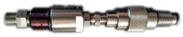 |
| Diamond hydrodynamic slitting drill bits | Φ113 mm | 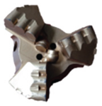 |
| Super high–pressure hose | Inner diameter 18.8 mm, working pressure 0–150 MPa |  |
| Shallow threaded drill pipe for hydrodynamic slit | Φ73 mm, pressure–bearing over 100 MPa | 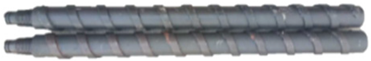 |
| High pressure jet | Φ75 mm, high– and low– pressure conversion threshold: 15 MPa | 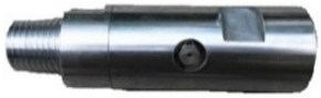 |
| Super high pressure clarified water pump | Rated flow rate 132 L/min, rated pressure 105 MPa |  |
| Hole sealer | Pressure–bearing 1–20 MPa; hose contraction coefficient: 60% |  |
| Fractured Area | Unfractured Areas | ||||
|---|---|---|---|---|---|
| Measurement Point Serial Number | Convergence of the Roof and Floor/m | Convergence of the Two Buttocks/m | Measurement Point Serial Number | Convergence of the Roof and Floor/m | Convergence of the Two Buttocks/m |
| 1 | 1.032 | 0.592 | 6 | 1.069 | 0.637 |
| 2 | 0.869 | 0.577 | 7 | 0.966 | 0.643 |
| 3 | 0.774 | 0.515 | 8 | 1.187 | 0.657 |
| 4 | 0.825 | 0.560 | 9 | 1.142 | 0.671 |
| 5 | 0.806 | 0.571 | 10 | 1.251 | 0.658 |
Publisher’s Note: MDPI stays neutral with regard to jurisdictional claims in published maps and institutional affiliations. |
© 2022 by the authors. Licensee MDPI, Basel, Switzerland. This article is an open access article distributed under the terms and conditions of the Creative Commons Attribution (CC BY) license (https://creativecommons.org/licenses/by/4.0/).
Share and Cite
Zhang, Z.; Ning, J.; Wang, J.; Wang, K.; Yang, S.; Yan, R.; Sun, G.; Du, M. Coal Pillar Stress Weakening Technology and Application by Gob-Side Entry Driving and Hydraulic Roof Cutting in Deep Shafts Mines. Processes 2022, 10, 827. https://doi.org/10.3390/pr10050827
Zhang Z, Ning J, Wang J, Wang K, Yang S, Yan R, Sun G, Du M. Coal Pillar Stress Weakening Technology and Application by Gob-Side Entry Driving and Hydraulic Roof Cutting in Deep Shafts Mines. Processes. 2022; 10(5):827. https://doi.org/10.3390/pr10050827
Chicago/Turabian StyleZhang, Zhi, Jianguo Ning, Jun Wang, Kun Wang, Shang Yang, Ruyu Yan, Guoqing Sun, and Minghao Du. 2022. "Coal Pillar Stress Weakening Technology and Application by Gob-Side Entry Driving and Hydraulic Roof Cutting in Deep Shafts Mines" Processes 10, no. 5: 827. https://doi.org/10.3390/pr10050827
APA StyleZhang, Z., Ning, J., Wang, J., Wang, K., Yang, S., Yan, R., Sun, G., & Du, M. (2022). Coal Pillar Stress Weakening Technology and Application by Gob-Side Entry Driving and Hydraulic Roof Cutting in Deep Shafts Mines. Processes, 10(5), 827. https://doi.org/10.3390/pr10050827