Article

Mechanical Behavior and Optimization of Tubing String with Expansion Joint during Fracturing in HTUHP Wells

1
State Key Laboratory for Performance and Structure Safety of Petroleum Tubular Goods and Equipment Materials, CNPC Tubular Goods Research Institute, Xi’an 710077, China
2
State Key Laboratory of Oil and Gas Reservoir Geology and Exploitation, Southwest Petroleum University, Chengdu 610500, China
*
Authors to whom correspondence should be addressed.
Processes 2022, 10(6), 1063; https://doi.org/10.3390/pr10061063
Submission received: 29 April 2022 / Revised: 16 May 2022 / Accepted: 20 May 2022 / Published: 26 May 2022
(This article belongs to the Section Energy Systems)

Abstract

:
During the formation testing in high-temperature (HT) and ultra-high-pressure (UHP) wells, one of the major challenges is packer failure in the downhole caused by high-rate fracturing. In such a case, the axial shrinkage trend of the tubing string could be caused by the sudden drop in temperature, but the actual axial length of the tubing string would not change because of the constraints at wellhead and packer. Therefore, this could lead to the upward pull-out of the packer that is due to excessive load from the tubing string. This out-of-control downhole pressure often leads to irreversible consequences, even well abandonment. An expansion joint, as a movable splicer, has the characteristic of mitigating packer load, which can theoretically enhance packer safety. To study the protective effect of an expansion joint on the packer quantitatively, the microscopic characteristics and macroscopic properties of the tubing material (13Cr110) are obtained through experimental tests. Moreover, the mechanical properties of the material at different temperatures are also tested. Then, the testing results are extended to modeling the finite element model (FEM) of the whole section of tubing string with the expansion joint—casing and simulating its internal force changes under fracturing conditions with different injection rates. Our simulation results indicated that an expansion joint can significantly change the distribution of the internal forces in the tubing string, and this change can effectively reduce the load on the packer. Eventually, a tubing string buckling identification plate that considers the injection rate and expansion joint–packer length is obtained to optimize the placement of an expansion joint in the tubing string. Our work can provide a detailed theoretical reference and basis for an expansion joint in field application.

1. Introduction

Currently, the provision of conventional oil and gas resources cannot meet the rapid growth of energy consumption [1]. Hence, the developed activities of unconventional reservoirs have drawn growing attention from energy companies [2]. It is well known that more than half of unconventional resources generally exist in deeper formations, which also means a high-temperature and high-pressure (HTHP) environment [3,4]; the downhole temperature could be up to 150~240 °C, and the original formation pressure could be up to 140~240 MPa [5]. Under such a harsh environment, the high fracture pressure is necessary to ensure the smooth development of a fracturing job. Meanwhile, the high fracture pressure usually accompanies a large injection rate of fracture fluid, which leads to a drop in temperature. These factors would cause the tubing to have a tendency to shrink, and excessive force would act on the packer, thereby causing it to fail. Consequently, to avoid the occurrence of packer failure, installing an expansion joint is a feasible mitigation to compensate for and absorb the axial deformation of the tubing during fracturing.
Actually, the importance of an expansion joint had been highlighted in some previous research and its application covers numerous fields, e.g., chemical industry, petroleum, electricity, etc. Some scholars researched the mechanical properties of expansion joints by creating simplified formula and FEM. Rao et al. [6] studied the dynamic stability and natural frequency of an expansion joint, and the correctness of the simplified formula (defined in EJMA, expansion joint manufacturers association) is verified by a dynamic model. Kiryukhin et al. [7] carried out influence-factor analysis of expansion joint vibration using the theory of vibration mechanics, and the high-pressure pipeline expansion joint is designed to avoid fatigue damage caused by pipeline vibration. Kiryukhin et al. [8] analyzed the vibration deformation of expansion joints in a pipeline with the physical model of fluid–solid coupling, and found that the effect of vibration frequency was a change in pressure in the pipeline.
The above research results present that the expansion joint can alleviate the vibration of ground pipelines based on dynamic calculation. However, more features of the expansion joint are put forward to meet the increasingly demanding working environment. Belilovets et al. [9] studied the compensation effect of underground heating pipelines with expansion joints, and developed a joint design to deal with a large-temperature-difference environment. Guo et al. [10] analyzed the flexibility of UHV (ultra-high vacuum) transmission pipelines based on the stress distribution by Caesar II software. Novikov et al. [11] developed a physico-mathematical model to measure the reliability performance of bellows expansion joints, and found that fatigue and wear are the two most significant factors that reduce the strength of the joint. Liu et al. [12] calculated the load change of the hydrostatic pressure at the flange connection after the expansion joint was installed and found that the bolt load and the flange moment were significantly reduced because of the expansion joint. Sun et al. [13] carried out the calculation of the change in a Mises stress distribution in an expansion joint under high-temperature and high-flow-rate media by fluent software; meanwhile, the temperature distribution of the joint is obtained. Yang et al. [14] studied the protective effect of an expansion joint in the string at high temperature, and declared that an expansion joint could alleviate the elongation of the pipe string when the temperature reaches 360 °C.
Most of the expansion joints mentioned in the above studies were attachments on surface pipelines; the downhole service environment is even harsher (e.g., higher temperature and pressure, more corrosive media, more varied conditions, etc.) compared to the ground environment. Research on the application of expansion joints in wellbores has only begun in recent years. Yang et al. [15] used a three-dimension finite element method to perform the deformation of the tubing string, and developed a process for calculating the mechanical behavior of the completion and testing the tubing string with the expansion joint. Song et al. [16] reported the case involving the application of expansion joints during zonal fracturing in HTHP gas wells, and the results presented that the existing problems, such as the high axial stress of the packer, poor sealing performance of the packer, and the high tubing stress, were improved through the addition of expansion joints in the tubing string.
Previous work thus clearly demonstrated the mechanical characteristics of expansion joints and their specific applications in some fields; however, the whole well section string model with expansion joints has not been reported in previous research. Furthermore, such technical guidance and support are urgently needed in the oil field. Therefore, the FEM of the tubing string with expansion joints in the whole well section is established in this work for calculation and analysis to guide the field about using expansion joints to reduce the occurrence of packer failure and tubing damage during fracturing.

2. Physical Model during Fracturing

The temperature of the fracturing fluid inside the tubing string could drop significantly in a short period (≤30 min generally according to the field data) during fracturing, and this change is the main reason for the accumulation of internal force in a tubing string. 
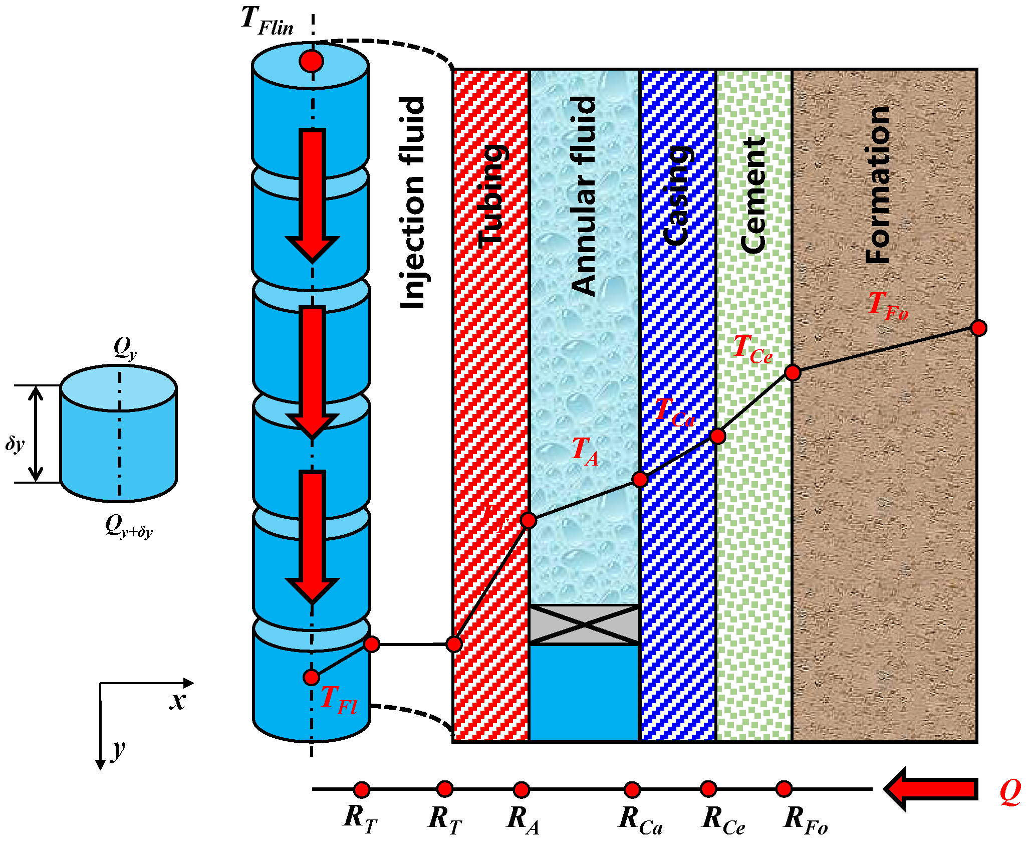
Figure 1 shows the physical model of the injection fluid and heat transfer in the borehole. It can be found that the injection fluid enters the tubing string at the wellhead with a temperature (TFlin) and flows down into the reservoir [17]. The rate of heat convection between the injection fluid and the inner wall of the tubing could affect fluid temperature (TFl) significantly. The heat generated is continuously carried out of the inside of the tubing, and a decrease of the temperature surrounding the borehole is caused. In general, heat generated in the far distance of the borehole diffuses to the wellbore by heat conduction because of the effect of temperature difference [17,18].
Fracturing fluid flowing in tubing can be divided into several units (the Y-axis is the axial direction of the wellbore), and the heat of a unit consists of four parts: (i) heat generated by convection heat transfer between fracturing fluid and tubing, (ii) the change of internal energy of the fracturing fluid, (iii) the heat carried by the down-flowing fracturing fluid, and (iv) thermal friction between fracturing fluid and tubing.
The heat generated by convection heat transfer Q1 between fracturing fluid and tubing per unit time dt can be presented as [17]:
d Q 1 = 2 π R T h T ( T T T F l ) δ y d t
where TT is the tubing temperature, TFl is the temperature of the fracture fluid in the tubing, RT is the inside radius of the tubing, and hT is the convection coefficient of the inner wall of the tubing.
The change in internal energy E of the fracturing fluid per unit time dt can be expressed as [17]:
d E = π R T δ y ρ f r c f r T F l t d t
where ρfr is the density of fracture fluid and cfr is the specific heat capacity of fracture fluid.
The heat Q2 carried by the down-flowing fracturing fluid per unit time dt can be illustrated as [17]:
d Q 2 = Q y Q y + δ y = q ρ f r c f r | T F l y T F l ( y + δ y ) | d t
where q is the injection rate.
The work from thermal friction W between fracturing fluid and tubing per unit time dt can be presented as [17]:
d W = Q F l δ y d t
where QFl is the energy source of fracture fluid unit. In addition, the equilibrium equations can be obtained as follows [17]:
q ρ f r c f r | T F l y T F l ( y + δ y ) | d t + 2 π R T h T ( T T T F l ) δ y d t + Q F l δ y d t = π R T δ y ρ f r c f r T F l t d t
Tubing string can be divided into several units; the heat of a unit consists of four parts [18]: (i) the change of internal energy, (ii) heat conduction between the outer wall and annular fluid, (iii) convection heat transfer between the inner wall and fracturing fluid, and (iv) axial heat conduction.
The change in internal energy E of a tubing unit per unit time dt can be illustrated as [18]:
d E = ρ t c t T T t π ( R A 2 R T 2 ) δ y d t
where ρt is the density of the tubing material, ct is the specific heat capacity of the tubing material, and RA is the inside radius of the annular fluid.
The equilibrium equations including the heat conduction Qra of the outer wall of the tubing—the annular fluid and the convection heat transfer of the inner wall—and the fracturing fluid per unit time dt can be presented as [18]:
d Q r a = 2 π μ T ( T A T T ) δ y d t 2 π R A h T ( T T T F l ) δ y d t
where μT is the thermal conductivity of the tubing material and TA is the temperature of annular fluid.
The axial heat conduction Qax of a tubing unit per unit time dt can be expressed as [18]:
d Q a x = μ T ( T T ( y + δ y ) y T T y y ) π ( R A 2 R T 2 ) δ y d t = μ T 2 T T y 2 π ( R A 2 R T 2 ) δ y d t
The equilibrium equations can be obtained as follows [18]:
μ T 2 T T y 2 + 2 R T h T ( T T T F l ) ( R A 2 R T 2 ) 2 μ T ( T A T T ) ( R A 2 R T 2 ) = ρ t c t T T t
The heat transfer relation of annular fluid–casing wall (inside radius of casing RCa, temperature TCa)–cement (RCe, TCe)- formation (RFo, TFo) could all be regarded as the heat conduction between multi-layer cylinder walls [19].
From the mechanical perspective, if there is no constraint on the tubing string, the structural stress could not occur as the temperature changes. However, when the string is fixed at wellhead and packer, the accumulation of the total internal forces ΔFall in the structure could be mainly caused by the effect of thermal expansion and contraction. Meanwhile, the internal force of the tubing string is also affected by buckling effect ΔF2, a friction effect caused by fluid flow ΔF3, ballooning effect ΔF4, and piston effect ΔF5 in ultra-deep HTUHP wells [20]. The total internal forces ΔFall of the tubing string could be calculated by different effects, as shown in Eq. (10). In our work, these effects are taken into account to calculate the mechanical behavior of the whole section of the tubing string.
Δ F a l l = Δ F 1 + Δ F 2 + Δ F 3 + Δ F 4 + Δ F 5  

3. Experimental

3.1. Materials and Specimen Preparation

The studied works on the micro-structure and mechanical properties of the tubing material have a positive effect on the accuracy of the mechanical calculation results. Therefore, a series of tests of metallographic observations and the macro-mechanical properties of 13Cr110 are carried out, manufactured according to 110 ksi (758 MPa) nominal yield strength [4].
The samples for the metallographic tests are cut from 13Cr110 tubing, and different grits of sandpaper (80, 200, 400, and 800) are used to grind the surface gradually [1].
In addition, in to obtain the mechanical property of 13Cr110, samples of base material are cut from a tubing section (Figure 2), and Figure 2 presents the schematic diagrams of the sample used for tensile test.

3.2. Metallographic Tests

A HCS 140 high-frequency infrared-ray carbon–sulfur analyzer (Shanghai Dekai Instruments Co., Shanghai, China) is employed to measure their chemical composition.
Moreover, an Axio Scope A1 (Carl Zeiss, Oberkochen, Germany) optical microscope is used for the metallographic observation of 13Cr110. Meanwhile, a ZEISS Gemini 500 (Carl Zeiss, Oberkochen, Germany) field-emission scanning electron microscope is employed to obtain the mapping maps.

3.3. Tensile Tests Method

To obtain the static mechanical properties of the 13Cr110, tensile tests are carried out at a temperature of 25 ± 1 °C. An MTS-180 tensile machine (MTS System Corp., Eden Prairie, MN, USA) is employed to run stress-strain tests with a velocity of 1 mm/min.
It is worth noting that the fluid temperature in the tubing varies dramatically during fracturing. Therefore, to further consider the change of material strength with the ambient temperature, the tensile tests of the tubing material are carried out at different temperatures. The testing process can be divided into three steps: ⅰ) the samples are placed in a heating furnace with air as the medium, ⅱ) the air is heated to a specified temperature by an electric heater and held for 10 min, with the testing temperatures determined to be 50 °C, 75 °C, 100 °C, 125 °C, and 150 °C, respectively, and ⅲ) the heated samples are stretched by the MTS-180 in time.
The metallographic observation of 13Cr110 is acquired, as shown in Figure 3a,b. It can be found that the inclusion in the study material is cyclic oxide, and the metallographic structure includes martensitic grains and a small amount of ferrite (Fe3C). Subsequently, a field-emission scanning electron microscope coupled with an EBSD probe is employed. Diffractograms are acquired at a tube voltage and current of 40 kV and 40 mA, respectively, a scan range of 5–90°, and a scan speed of 5°/min. Finally, to further explore the changes in grain size quantitatively, the results of the EBSD are analyzed by data analysis software. It is notable that the mapping maps (Figure 3c,d) can be used as an auxiliary diagram to clearly distinguish different grains in the inverse pole figure maps. The red region is the body-centered cubic grain, while the green region is the face-centered structure Fe3C. Meanwhile, grain size analysis reveals that the average grain size is 19.38 μm in the base alloy. In general, the grain distribution of the tubing material studied is uniform.

3.4. Mechanical Property Results

The mechanical property results of 13Cr110 can be characterized from the stress-strain curve in Figure 4, and the mechanical parameters are listed in Table 1. According to the curve, it can be seen that this material presents obvious elastic and plastic stages, and when the strain reaches about 6%, the stress of the material reaches the tensile strength σu. Based on the curve in Figure 4, several key parameters can be extracted in Table 1, and it can be found that the tested average yield strength σy of 13Cr110 is 831.76 MPa, the average ultimate strength σu is 922.46 MPa, and the average percentage elongation δ is 19.16%. Meanwhile, the test results of material strength at different temperatures are presented in Figure 5. It can be seen that the yield strength, tensile strength, and elongation of the material obviously decrease with the increase of temperature. The yield strength σy of 13Cr110 under different temperatures (50 °C, 75 °C, 100 °C, 125 °C, and 150 °C) are 831.7 MPa, 805.8 MPa, 786.5 MPa, 765.3 MPa, and 742.7 MPa, respectively. The ultimate strengths σu are 922.4 MPa, 902.7 MPa, 885.6 MPa, 865.5 MPa, and 846.5 MPa, respectively. The percentage elongations δ are 19.16%, 18.01%, 17.2%, 16.11%, and 14.99%, respectively. These experimental results consider the strength change because the change in temperature is also extended to modeling the tubing string to obtain an accurate simulation.

4. Stress Change of Two Types of the Tubing String during Fracturing

4.1. Modeling

According to the data from an actual HTUHP well, H1 in China, the FEM of the whole section of a tubing string casing (Figure 6) is established to simulate the stress change of the tubing string when it enters the casing and encounters fracturing conditions. The initial condition of the tubing string is 1.2 g/cm3 density brine and the temperature profile is linearly distributed (wellhead 16.7 °C, bottom 156 °C), and the fracturing pressure of the reservoir reaches 165.1 MPa. Meanwhile, there are six parts that consist of φ114.3 (outer diameter, mm) + T12.7 (wall thickness, mm) − 625 m (well depth), φ114.3 + T9.65 – 5210 m, expansion joint-6360 m (stroke is 8.56 m), φ88.9 + T9.53 – 6301 m, φ73.2 + T7.02 – 7099 m and φ73.2 + T5.51 – 7550 m involved in the whole tubing model. The casing diameter is 139.7 mm, wall thickness is 12.7 mm, and well depth is 7610 m. On the other hand, the mechanical properties measured in previous experimental work are assigned to the tubing string assembled in the FEM, and the stress-strain relationships of 13Cr110 are set in terms of the results in Section 3.3; meanwhile, the casing is considered to be a rigid body.
The tubing string without expansion joints can be seen as a complete beam, so, the transfer of inner forces between adjacent elements is continuous in such a structure. In addition, its mechanical behavior, including buckling, vibration, and erosion [20,21], has been studied by many scholars. However, the insertion of expansion joints could break up this continuous transmission of forces abruptly. Therefore, the force distribution of whole section of tubing string could be completely changed.
To further study the effect of expansion joints on the mechanical behavior of the tubing string, two kinds of structures, including a string with an expansion joint and a string without an expansion joint, are calculated in different fracturing conditions in this work. Meanwhile, according to the actual working conditions, the differences between the two kinds of string are compared quantitatively.
The working mechanism of the expansion joint is presented in Figure 7. Initially, two pins hold the upper pipe in place to prevent it from sliding freely in the outer pipe, but when the shear force generated by the relative movement of the upper pipe and the lower pipe exceeds the critical value of the pin, the pins could be sheared. When the pin is cut, the upper pipe is free to move without resistance inside the outer pipe, and the weight of the tubing string (section of expansion joint–packer) is supported on the packer. To simulate the working mechanism of the expansion joint in FE software, the function of a translator connection is employed. However, a translator connection module in the software cannot take into account the effect of the pin or the tension between the upper pipe and the lower pipe in the pull-out state.
Therefore, the PYTHON script is employed to implement the display of the contour, Figure 8 presents the schematic diagram of the method to obtain a working mechanism of the expansion joint displayed in FE software, and the logic is as follows: (i) the value of the axial force at an expansion joint can be extracted based on the stress field calculated in FEM, and it is compared to the critical values of the pins, (ii) if the value exceeds the critical value, the translator connection is activated; otherwise, the mechanical calculations could be carried out based on the tubing string without expansion joints, and (iii) after the pins are cut, when the combined deformation (Lup + Ldo, Lup is the upward displacement of the bottom end of the upper pipe, Ldo is the downward displacement of the top end of the lower pipe) exceeds the stroke length limit of the expansion joint under the specified working condition, the mechanical simulation of the tubing string could still be carried out, and the force calculation at the joint is based on the tubing string without expansion joint to transfer the tensile effect.
Figure 9 illustrates the load application procedures for the whole section of tubing string in FEM, and the loads are applied in four steps, as described in Figure 9: (i) the whole section of tubing string is suspended at the wellhead, and it is subjected to its own gravity, as can be seen in Figure 9a; meanwhile, the section at the bottom of the tubing string is subjected to an upward liquid column pressure from 1.2 g/cm3 density brine (liquid pressure at well bottom reaches 88.87 MPa), (ii) when the whole section of tubing string deforms adequately because of its own weight and liquid pressure, the packer (well depth 7300 m) is set. The setting of the packer means that a point (7300 m) on the tubing string is constrained at its current position. Meanwhile, after the packer is set, 80 kN axial slack-off force is applied to the tubing at wellhead, as can be seen in Figure 9b. The axial slack-off force is to further ensure the safety of the packer. (iii) After 80 kN axial slack-off force is applied, a point (wellhead) on the tubing string is also constrained at its current position. It can be seen from Figure 9c that although the 80 kN force is relatively small, it can also cause axial deformation of the tubing string. (iv) The initial mechanical state of the tubing string can be determined through the process shown in Figure 9a–c, and the final step is to calculate the stress state of whole section of tubing string according to the pressure and temperature during fracturing, as shown in Figure 9d.

4.2. Simulation Results

Figure 10 illustrates the fluid temperature and pressure under different injection rates vs. well depth in this case. These results are calculated through a difference method and iteration based on the transient heat transfer theory from Section 2. The thermodynamic parameters of the involved materials are from reference [17,18,19]. It can be seen from Figure 10a that the average fluid temperature in the tubing string decreases with the increase of injection rate. The fluid temperature in the tubing string drops compared with the initial temperature during fracturing at any injection rate, and the resulting temperature difference can be considered as the difference between the fracturing temperature (Figure 10a) and formation temperature (Figure 6). Figure 10c presents the temperature difference vs. injection rate at different well depths, and it can be found that the temperature difference increases with the increase of well depth. Meanwhile, there are three sections where the temperature did not follow one temperature gradient with the depth of the well at the same injection rate (0~5210 m, 5210~6301 m, and 6301~7550 m); this is caused by the different flow velocity that is due to the differences of inner diameters of pipes. The temperature distributions are fitted into a series of formulas to facilitate the application of loads in FE software, as shown in Table 2.
On the other hand, Figure 10b presents the fluid pressure under different injection rates vs. well depth. The pressure level in the tubing increases when the injection rate increases. Meanwhile, the friction pressure loss is more obvious with the increase of rate. The fitting formulas of pressure distribution in the tubing string under different injection rates are shown in Table 3. The annular pressure of the tubing is calculated according to the liquid column pressure of 1.2 g/cm3 density brine.
Through the simulation calculation in FEM, the stress of the whole section of tubing string can be extracted. It is worth noting that the change of axial force distribution in the tubing string is significant because of the expansion joint. Figure 11a illustrates the axial force of the tubing string without an expansion joint under different injection rates vs. well depth. It can be seen that the axial force of the tubing string without an expansion joint in the section of the wellhead–packer is the tensile state. The main reason for the apparent tensile axial force of the tubing string without an expansion joint is the rapid drop of temperature during fracturing. When the temperature drops, the length of the tubing string could shorten if there is no constraint. However, when there are constraints at the wellhead and packer, respectively, the stress can accumulate inside the string wall. Obviously, the direction of the axial load from the tubing on the packer is upward, and the upward force could increase with the injection rate. It can be analyzed that the packer is at risk of being pulled out when the injection rate exceeds a certain level.
Therefore, to avoid this risk, the expansion joint is considered as a component to be inserted into the tubing string. Figure 11b shows the axial force of the tubing string with an expansion joint under different injection rates vs. well depth. Due to the working mechanism of the expansion joint described in Figure 7, the axial force of the tubing string with an expansion joint in the section of the joint–packer is the compression state. Moreover, the direction of the axial force from the tubing string on the packer becomes downward, and the downward force could also increase with the injection rate. This is because the fluid pressure on the joint end increases with the injection rate, and the fluid pressure could compress the section of the joint–packer downward. Meanwhile, the fluid pressure could compress the section of the joint–wellhead upward.
Figure 12 describes the axial force on the packer from the two kinds of tubing string vs. injection rate. It is worth noting that the axial force in Figure 12 is only from the upper tubing string on the packer. It can be found that the forces of the tubing string without an expansion joint under different injection rates are all tensile states, and the force increases with the injection rate. This is because the larger the rate, the lower the temperature level throughout the string. On the other hand, the forces of the tubing string with an expansion joint under different injection rates all are all compress states, and the force also increases with the injection rate. These forces are caused by two factors: (i) the weight of the tubing string (section of the expansion joint–packer) is supported on the packer, and the force is the same when the expansion joint is placed in the same position, and (ii) the level of inner pressure could increase with the injection rate (Figure 10b), so the pressure from the fracturing fluid at the joint’s position could increase the down-force on the end of the joint.
Figure 13 illustrates the axial force and annular differential pressure on the packer under different injection rates compared with the packer envelope. The packer envelope data are from the manufacturer’s test reports in the field, and the six boundary points (this represents the safety critical point of the packer under the combined action of axial force Fa and annular differential pressure Pa, and it is also defined as the Fa–Pa point) are 6.85 MPa–870.64 kN, 78.24 MPa–0 kN, 78.24 MPa–553.78 kN, −33.89 MPa–−553.78 kN, −91.24 MPa–0 kN, −47.29 MPa–870.64 kN, and 6.85 MPa–870.64 kN, respectively. It can be seen that the Fa–Pa points of the packer from the tubing string with an expansion joint under different injection rates are enclosed in the packer envelope. However, from the perspective of the tubing string without an expansion joint, the packer is at risk of failure when the injection rate exceeds 3.5 m3/min. It can be judged from the axial force and annular differential pressure that the failure mode of the packer is pull-out upward. It is clear by comparison that the addition of an expansion joint plays a positive role in packer safety.

5. Discussion

5.1. Buckling

Another important factor affecting the force distribution of the whole section of tubing string is the position of the expansion joint, also presented as expansion joint–packer length in this work. From the above simulation results, it appears that the longer the expansion joint–packer length, the safer the packer. However, it is worth noting that buckling deformation could be triggered when the compression axial force of the tubing string exceeds a certain critical value. Buckling of the tubing string is the primary cause of many accidents, e.g., the decrease in residual strength of the pipe, an increase in the erosion of wall thickness, an increase in stress corrosion cracking risk, and galvanic corrosion between casing and tubing [21].
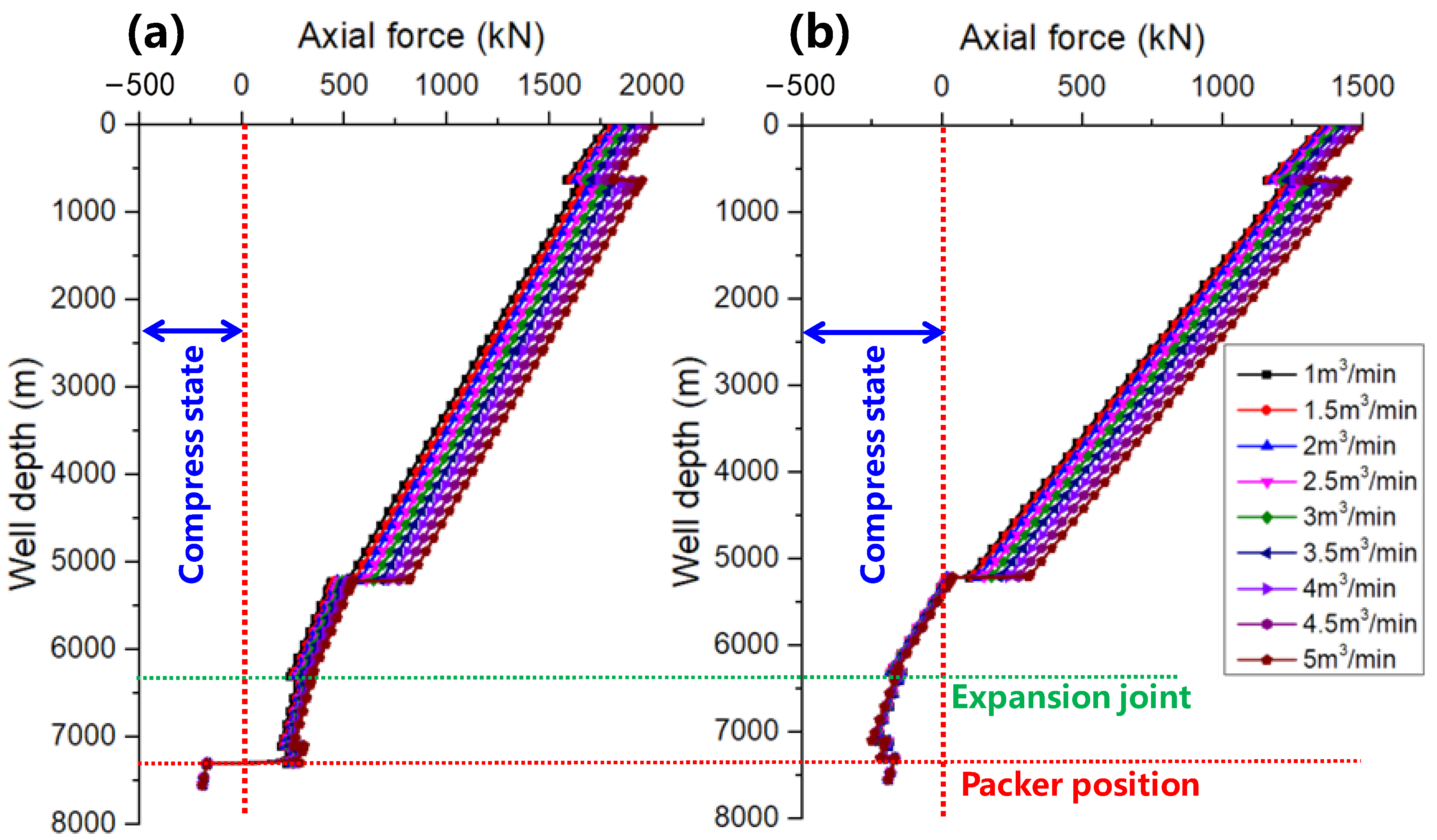
Figure 14 illustrates the axial force of the tubing string above the packer (Fap) vs. injection rate and expansion joint–packer length. It can be found that Fap increases significantly with the increase of the injection rate and expansion joint–packer length, the comparison from Figure 14 shows that the expansion joint–packer length has a more obvious effect on Fap than the injection rate.
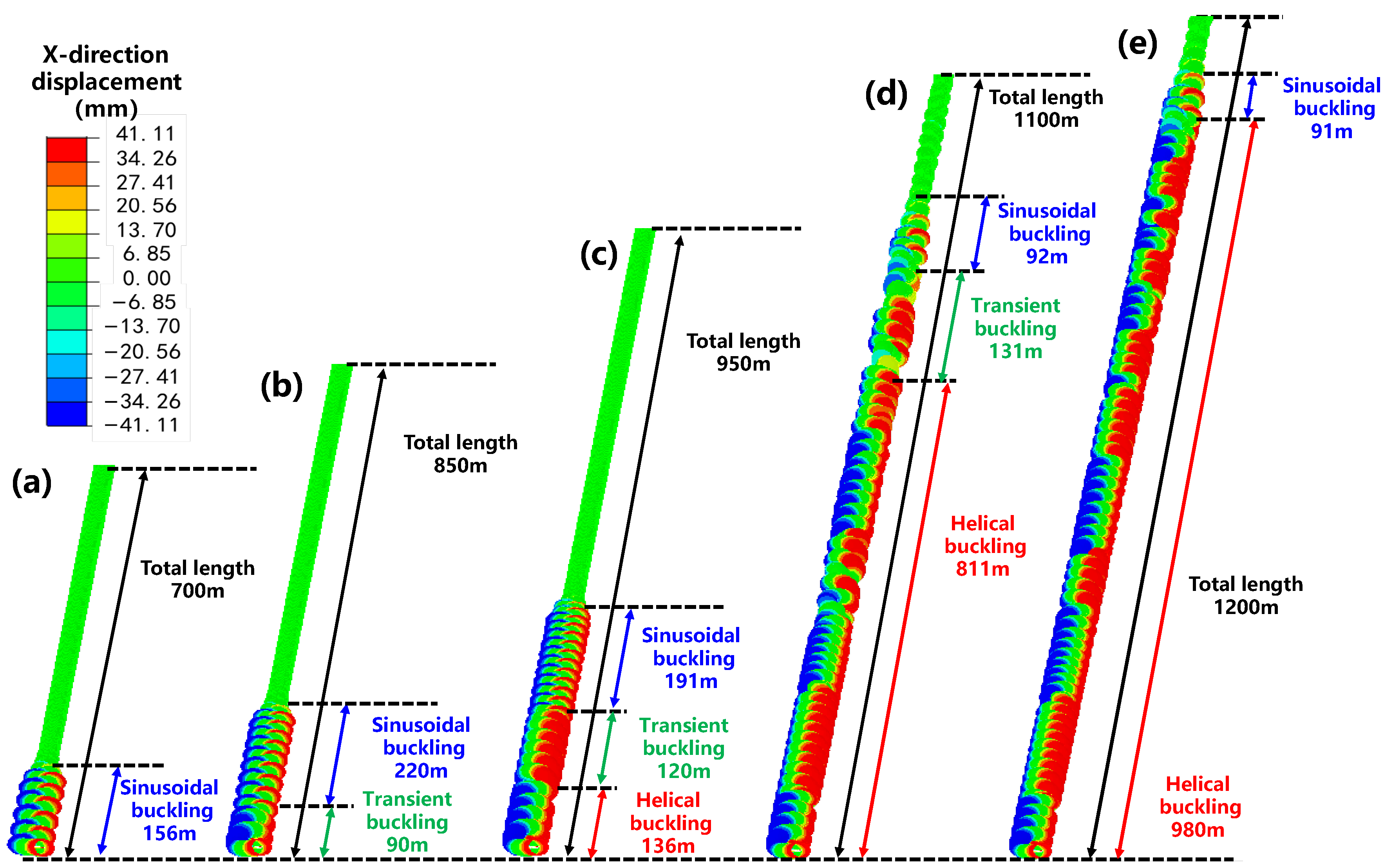
To further study the relationship between axial force and tubing buckling deformation, the buckling deformation of the tubing string calculated by FEM under five working conditions (defined as I, II, III, IV, and V in 
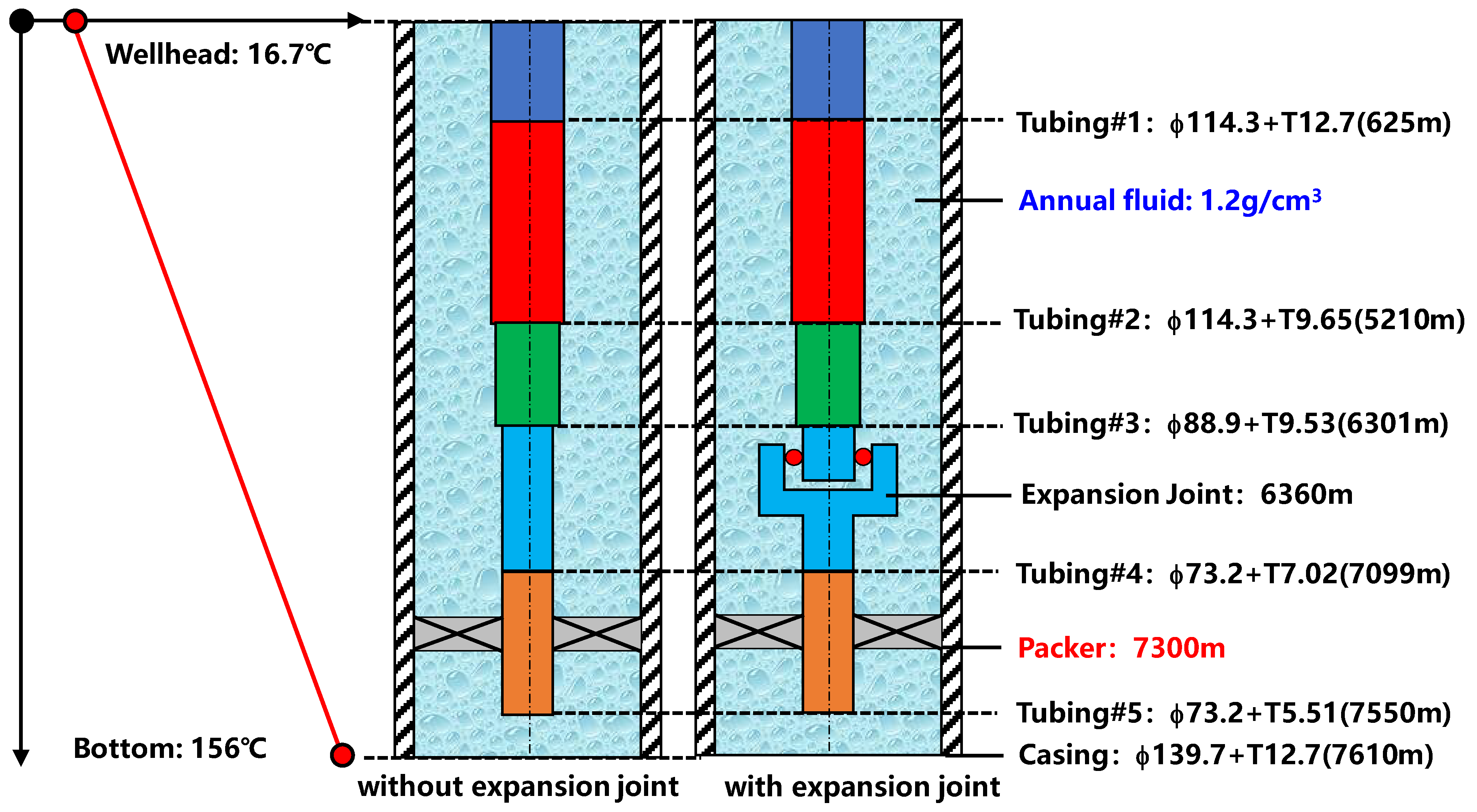
Figure 14) is extracted and compared. In addition, several working conditions are injection rate 2 m3/min–expansion joint–packer length 700 m, injection rate 2 m3/min–expansion joint–packer length 850 m, injection rate 2.5 m3/min–expansion joint–packer length 950 m, injection rate 3 m3/min–expansion joint–packer length 1100 m, and injection rate 4.5 m3/min–expansion joint–packer length 1200 m, respectively. Figure 15 presents the tubing buckling deformation (expansion joint–packer) under five defined working conditions. It is obvious that the buckling deformation of the tubing string becomes more serious with the increase of expansion joint–packer length.
The severity of the buckling deformation of the tubing can be evaluated in two ways: (i) the length of the buckling tubing string and (ii) the categories of buckling deformation (including sinusoidal buckling, transient buckling, and helical buckling). It is known that sinusoidal buckling is a relatively mild deformation, while helical buckling is a more serious form according to reference [22]. When expansion joint–packer length increases from 700 m to 1200 m, the buckling deformation of the tubing changes significantly: (i) the length of the buckling tubing string are 156 m, 310 m, 447 m, 992 m, and 1071 m, respectively, and (ii) the form of buckling deformation changes from sinusoidal buckling to helical buckling.
Moreover, the contact between tubing and casing caused by buckling deformation is the initial cause of many risks, e.g., (i) the galvanic corrosion of dissimilar joints (tubing (13Cr110) and casing (150 V) in HTHP wells) could be caused, and this phenomenon has been reported by many scholars, (ii) the contact force as an additional load could reduce the safety factor of the tubing string; meanwhile, excessive contact forces may cause secondary deformation of the tubing, and (iii) helical buckling may cause the self-lock of the tubing string in the casing.
Figure 16 shows contact between tubing and casing under six working conditions from the perspective of the well bottom. When the axial force at the bottom is 100 kN, no deformation occurred, but the sinusoidal buckling of the tubing is initiated at 180 kN axial force. Then, when axial forces reach 250 kN, a typical helical buckling is triggered, and the contact region between tubing and casing is approximately a spiral belt. It can be seen that the helical buckling becomes more pronounced as the axial force increases.

5.2. Movement of Expansion Joint

Moreover, the stroke length of the expansion joint is also an important factor to be considered in the design because if the expansion joint is pulled apart during high-pressure fracturing, it could have disastrous consequences. When the deformation (Lup + Ldo) exceeds the stroke length limit of the expansion joint under the specified working condition, the expansion joint would be stretched. It can be imagined that this tensile force is determined by the injection rate and the position of the joint along the well depth. Figure 17a illustrates the changes in movement of an expansion joint under different field conditions. When the joint is placed in a certain position, the movement increases with the increase of rate. Meanwhile, the movement increases with the increase of the depth of placement position. However, it is worth noting that the movement reaches 7.38 m (7.38 m is the stroke limit of the expansion joint in this work) under five conditions (placement position 6200 m–injection rate 4.5 m3/min, 6200 m–5 m3/min, 6360 m–4.5 m3/min, 6360 m–5 m3/min, 6450 m–5 m3/min); it can be believed that the expansion joint is stretched in these conditions. Therefore, the values of the corresponding five tensile forces are presented in Figure 17b. It can be seen that the values of the tensile forces of the joint exceed the force limit (150 kN) in two conditions (167.34 kN in 6200 m–5 m3/min and 158.46 kN in 6360 m–5 m3/min).
It can be known from the above systematic analysis that the packer’s safety factor can be significantly improved by adding an expansion joint to the tubing string to meet the requirements of high-rate injection. However, the expansion joint could be pulled out under certain working conditions; meanwhile, string buckling is also easily caused. Therefore, packer safety, stress distribution of the tubing string, buckling deformation of the tubing string, and stroke length of the expansion joint all need to be considered simultaneously when using it. Hence, the design principle is to minimize the stress level of the tubing string to ensure the safety of the packer, while avoiding string buckling and joint fracture. If these factors cannot meet the requirements simultaneously, sinusoidal buckling is acceptable. However, helical buckling is definitely not allowed because such deformation can cause a series of hidden dangers, e.g., erosion, wear, galvanic corrosion, etc. Eventually, there is a suggestion that if the expansion joint is necessary to meet the fracturing conditions, the supply of the specific identification plate for a well could provide a theoretical basis for the design of the string and expansion joint (including the placed position and stock length limit). It could play a positive role in the safety construction of the site.

6. Conclusions

(1) The axial force of the tubing string without an expansion joint in the section of wellhead–packer is the tensile state that is due to a rapid drop of temperature during fracturing (in our case, the axial force increases from 215 kN to 283 kN when the injection rate increase from 1 m3/min to 5 m3/min). In addition, the direction of the axial load from the tubing on the packer is upward, and the upward force could increase with the injection rate.
(2) Due to the working mechanism of the expansion joint, the axial force of the tubing string in the section of joint–packer changes to the compression state. Moreover, the direction of the axial force from the tubing string on the packer becomes downward, and the downward force could also increase with the injection rate; this force on the packer is caused by two factors: (i) the weight of the tubing string (section of expansion joint–packer) and (ii) the inner pressure from the fracturing fluid on end of joint.
(3) The expansion joint can significantly change the distribution of internal forces in the tubing string, and this change can effectively reduce the load on the packer. The axial force could change from a tensile state to a compression state. Numerically, the absolute value of the axial force in the compression state is 80%~95% of that in the tensile state under different injection rates.
(4) The packer safety, stress distribution of the tubing string, buckling deformation of the tubing string, and stroke length of the expansion joint all need to be considered simultaneously when using an expansion joint in the design of the tubing string. If these factors cannot meet the requirements simultaneously, sinusoidal buckling is acceptable, but helical buckling is definitely not allowed. Meanwhile, the supply of the specific identification plate for a well could provide a theoretical basis for the design of the string and expansion joint (including the placed position and stock length limit).

Author Contributions

Y.M.: Methodology, investigation, writing—original draft. S.Y.: conceptualization, resources, writing—review and editing. L.H.: formal analysis, validation, investigation, funding acquisition. J.W.: writing—review and editing, investigation. Z.L.: validation, investigation. All authors have read and agreed to the published version of the manuscript.

Funding

This research was funded by the Innovative Talents Promotion Program—Young Science and Technology Nova Project (2021KJXX-63), the Research on key technology of casing damage evaluation and repair in oil and gas wells (2021DJ2705) and the Study on key technology of stimulation and modification for Gulong shale oil (2021ZZ10-04).

Institutional Review Board Statement

Not applicable.

Informed Consent Statement

Not applicable.

Data Availability Statement

Not applicable.

Conflicts of Interest

The authors declare that there are no conflicts of interest.

Abbreviation

RTinside radius of the tubingm
hTconvection coefficient of the inner wall of the tubingW/m2/ °C
TTtubing temperature °C
TFltemperature of fracture fluid in the tubing °C
TAtemperature of annular fluid °C
TCacasing temperature °C
TCecement temperature °C
TFoformation temperature °C
ρfrdensity of fracture fluidkg/m3
cfrspecific heat capacity of fracture fluidJ/kg °C
qinjection ratem3/s,
QFlenergy source of fracture fluid unitW/m
RAinside radius of the annular fluidm
RCainside radius of the casingm
RCeinside radius of the cementm
RFoinside radius of the formationm
ρtdensity of the tubing materialkg/m3
ctspecific heat capacity of the tubing materialJ/kg °C
μtthermal conductivity of the tubing materialW/m/ °C
ΔFalltotal change of internal force in tubingN
ΔF1force change from thermal effectN
ΔF2force change from buckling effectN
ΔF3force change from friction effect due to fluid flowN
ΔF4force change from ballooning effectN
ΔF5force change from piston effectN

References

  1. Mou, Y.; Lian, Z.; Li, W.; Zhong, X.; Li, J.; He, Y.; Cao, J.; Eliaz, N. The effect of friction welding on the mechanical properties and corrosion fatigue resistance of titanium alloy drill pipe. Fatigue Fract. Eng. Mater. Struct. 2022, 45, 466–481. [Google Scholar] [CrossRef]
  2. Mou, Y.; Lian, Z.; Lin, T.; Zhang, Q.; Liu, Y. Study on Fatigue of Tubing Joint Thread Induced by Vibration in HTHP Ultradeep Wells. J. Press. Vessel. Technol. 2020, 142, 031502. [Google Scholar] [CrossRef]
  3. Wang, H.; Ma, F.; Tong, X.; Liu, Z.; Zhang, X.; Wu, Z.; Li, D.; Wang, B.; Xie, Y. Assessment of global unconventional oil and gas resources. Pet. Explor. Dev. 2016, 43, 850–862. [Google Scholar] [CrossRef]
  4. Mou, Y.; Lian, Z.; Sang, P.; Yu, H.; Zhang, Q.; Li, R. Study on water hammer effect on defective tubing failure in high pressure deep gas well. Eng. Fail. Anal. 2019, 106, 104154. [Google Scholar] [CrossRef]
  5. Liu, X.; Zhu, H.; Zhu, Y. Drilling lfuid design and test method for offshore ultra-HTHP wells and new drilling lfuid technology abroad. Oil Drill. Prod. Technol. 2013, 36, 47–52. [Google Scholar]
  6. Rao, N.S.; Radhakrishna, M.; Prasad, A. Dynamic Stability and Natural Frequency of Composite Corrugated Bellows Expansion Joint. Appl. Mech. Mater. 2013, 367, 68–72. [Google Scholar] [CrossRef]
  7. Kiryukhin, A.V.; Milman, O.O.; Ptakhin, A.V. A Search for the Physical Principles of Improving the Power Unit Pipeline Expansion Joint with Fluid Vibro-Isolating Properties. Int. J. Appl. Eng. Res. 2016, 11, 11176–11183. [Google Scholar]
  8. Kiryukhin, A.V.; Milman, O.O.; Ptakhin, A.V.; Serezhkin, L.N.; Kondratev, A.V. Development and Calculation-experimental Analysis of Pressure Pulsations and Dynamic Forces Occurrence Models in the Expansion Joints of Pipelines with Fluid. Int. J. Appl. Eng. Res. 2017, 12, 8209–8216. [Google Scholar]
  9. Belilovets, V.I.; Lipovka, Y.L. Designing underground trenchless thermally pre stressed heat supply pipelines with expansion joints. Bull. Tomsk. Polytech. Univ. Geo Assets Eng. 2018, 329, 57–69. [Google Scholar]
  10. Guo, Y.; Jin, G.; Wang, Z.; Lu, Z.; Huang, J.; Huang, K. Research on the Influence of Bellows Expansion Joint Structure on the Strength of UHV Pipeline. High Volt. Appar. 2018, 54, 1–6. [Google Scholar]
  11. Novikov, A.; Amirkhanov, E.I.; Logunov, V.V. Physico-mathematical model for bellows expansion joint efficiency by different manufacturing technologies. IOP Conf. Ser. Mater. Sci. Eng. 2019, 560, 012149. [Google Scholar] [CrossRef]
  12. Liu, Y.; Fu, S. Load Change in Flanges Connected with Pipeline with Non-constrained Expansion Joint. Process Equip. Pip. 2020, 57, 74–77. [Google Scholar]
  13. Sun, R.; Wang, X. Application of Fluent Software in Expansion Joint Design. Pipeline Tech. Equip. 2021, 1, 48–51. [Google Scholar]
  14. Yang, F. Analysis and discussion on deformation of pipe string with seal in thermal recovery well. China Pet. Chem. Stand. Qual. 2011, 31, 170–171. [Google Scholar]
  15. Yang, X.; Shen, X.; Cui, X.; Wang, K.; Shen, G.; Wang, Z.; Qin, T. Stress and deformation characteristics of completion and testing tubing string with expansion joints for ultra-deep HTHP gas wells. Nat. Gas Ind. B 2020, 7, 101–108. [Google Scholar] [CrossRef]
  16. Song, P.; Xu, L.; Wang, J.; Li, Y.; Chen, F. Research and application of mechanical separate layer fracturing string in ultra-deep high-temperature and high-pressure gas well. Technol. Superv. Pet. Ind. 2021, 37, 39–43. [Google Scholar]
  17. Yang, M.; Zhao, X.; Meng, Y.; Li, G.; Zhang, L.; Xu, H.; Tang, D. Determination of transient temperature distribution inside a wellbore considering drill string assembly and casing program. Appl. Therm. Eng. 2017, 118, 299–314. [Google Scholar] [CrossRef] [Green Version]
  18. Yang, M.; Tang, D.; Chen, Y.; Lia, G.; Zhang, X.; Meng, Y. Determining initial formation temperature considering radial temperature gradient and axial thermal conduction of the wellbore fluid. Appl. Therm. Eng. 2019, 147, 876–885. [Google Scholar] [CrossRef]
  19. Yang, M.; Xie, R.; Liub, X.; Chen, Y.; Tang, D.; Meng, Y. A novel method for estimating transient thermal behavior of the wellbore with the drilling string maintaining an eccentric position in deep well operation. Appl. Therm. Eng. 2019, 163, 114346. [Google Scholar] [CrossRef]
  20. Lian, Z.; Mou, Y.; Liu, Y.; Xu, D. Buckling behaviors of tubing strings in HTHP ultra-deep wells. Nat. Gas Ind. 2018, 38, 89–94. [Google Scholar]
  21. Xu, J.; Mou, Y.; Xue, C.; Ding, L.; Wang, R.; Ma, D. The study on erosion of buckling tubing string in HTHP ultra-deep wells considering fluid–solid coupling. Energy Rep. 2021, 7, 3011–3022. [Google Scholar] [CrossRef]
  22. Zhang, Q.; Zhu, Y.; Xiao, Z.; Li, W.; Cui, W.; Yue, Q. On the post-buckling analysis of a circular column with cylindrical constraint under concentrated torque loading. Ocean. Eng. 2019, 188, 106261. [Google Scholar] [CrossRef]
Figure 1. The physical model of the injection fluid and heat transfer in the borehole.
Processes 10 01063 g001
Figure 2. The schematic diagrams of specimen used for tensile test.
Processes 10 01063 g002
Figure 3. Optical micrographs and EBSD data revealing the (a) cyclic oxide of the studied material, (b) typical micro-structures of 13Cr110, (c) grain boundaries in 13Cr110, and (d) inverse pole map of 13Cr110.
Processes 10 01063 g003
Figure 4. The stress-strain relationship of 13Cr110 (25 °C).
Processes 10 01063 g004
Figure 5. Tensile results of the 13Cr110 including yield strength (Rp0.2), ultimate strength (Rm), and elongation at break (δ).
Processes 10 01063 g005
Figure 6. The FE model of whole section tubing string casing.
Processes 10 01063 g006
Figure 7. The working mechanism of the expansion joint and its implementation in FEM.
Processes 10 01063 g007
Figure 8. The schematic diagram of the method to obtain a working mechanism of an expansion joint displayed in FE software.
Processes 10 01063 g008
Figure 9. The load application procedures for the whole section of tubing string: (a) gravity, (b) packer setting and slack-off force, (c) fix wellhead again, and (d) injection.
Processes 10 01063 g009
Figure 10. Fluid temperature and pressure under different injection rates vs. well depth: (a) temperature, (b) pressure, and (c) temperature difference.
Processes 10 01063 g010
Figure 11. Axial force of the two kinds of tubing string under different injection rates vs. well depth: (a) tubing string without expansion joint and (b) tubing string with expansion joint.
Processes 10 01063 g011
Figure 12. Axial force on the packer from the two kinds of tubing string vs. injection rate.
Processes 10 01063 g012
Figure 13. The axial force and annular differential pressure on the packer under different injection rates compared with the packer envelope.
Processes 10 01063 g013
Figure 14. The axial force of the tubing string at above packer vs. injection rate and expansion joint–packer length.
Processes 10 01063 g014
Figure 15. The tubing buckling deformation (expansion joint–packer) under five defined working conditions: (a) I condition, (b) II condition, (c) III condition, (d) IV condition, and (e) V condition.
Processes 10 01063 g015
Figure 16. Contact between tubing and casing under six working conditions from the perspective of the well bottom: (a) Ⅰ condition, (b) Ⅱ condition, (c) Ⅲ condition, (d) Ⅳ condition, (e) Ⅴ condition, and (f) Ⅵ condition.
Processes 10 01063 g016
Figure 17. The changes in movement of the expansion joint and corresponding tensile force under different field conditions: (a) movement and (b) tensile force borne by expansion joint.
Processes 10 01063 g017
Table 1. Static mechanical properties of the 13Cr110, as extracted from the stress-strain curves (25 °C).
No.Yield Strength σy, Rp0.2
(MPa)
Ultimate Strength σu,
(MPa)
Yield Ratio σyuElongation δ (%)
MeasuredMeanMeasuredMeanMeasuredMeanMeasuredMean
1842.72831.79928.33922.460.910.9019.1219.16
2817.82921.650.8919.01
3834.83917.40.9119.34
Table 2. The fitting formulas of temperature distribution in the tubing string under different injection rates (temperature is defined as T, de is depth).
Injection Rate
(m3/min)
Temperature (°C)
0~5210 m5210~6301 m6301~7550 m
1T = 2 × 10⁻⁷de2 + 0.007de + 15.36T = 0.0089de + 8.19T = −3 × 10⁻⁷de2 + 0.0126de − 7.12
1.5T = 5 × 10⁻⁸de2 + 0.0072de + 15.44T = 0.0089de + 4.01T = −1 × 10⁻⁶de2 + 0.0298de − 76.83
2T = 6 × 10⁻⁸de2 + 0.0071de + 15.44T = 0.0086de + 5.34T = −1 × 10⁻⁶de2 + 0.0253de − 60.09
2.5T = 2 × 10⁻⁷de2 + 0.0069de + 15.36T = 0.0082de + 9.32T = −4 × 10⁻⁷de2 + 0.0133de − 11.35
3T = 7 × 10⁻⁸de2 + 0.007de + 15.41T = 0.0084de + 6.48T = −1 × 10⁻⁶de2 + 0.0233de − 51.79
3.5T = 7 × 10⁻⁸de2 + 0.0069de + 15.42T = 0.0081de + 7.75T = −8 × 10⁻⁷de2 + 0.0207de − 41.64
4T = 1 × 10⁻⁷de2 + 0.0068de + 15.39T = 0.0079de + 9.51T = −5 × 10⁻⁷de2 + 0.0155de − 20.21
4.5T = 9 × 10⁻⁸de2 + 0.0069de + 15.40T = 0.0079de + 8.59T = −7 × 10⁻⁷de2 + 0.0183de − 32.41
5T = 1 × 10⁻⁷de2 + 0.0068de + 15.39T = 0.0078de + 9.40T = −6 × 10⁻⁷de2 + 0.0173de − 27.49
Table 3. The fitting formulas of pressure distribution in the tubing string under different injection rates (pressure is defined as P, de is depth).
Injection Rate
(m3/min)
Pressure Expression (MPa)
1P = −1 × 10⁻⁷de2 + 0.0125de + 76.96
1.5P = −2 × 10⁻⁷de2 + 0.013de + 81.674
2P = −1 × 10⁻¹⁰de3 + 1 × 10⁻⁶de2 + 0.0093de + 90.16
2.5P = −2 × 10⁻¹⁰de3 + 2 × 10⁻⁶de2 + 0.0078de + 98.73
3P = −3 × 10⁻¹⁰de3 + 2 × 10⁻⁶de2 + 0.0062de + 108.64
3.5P = −3 × 10⁻¹⁰de3 + 3 × 10⁻⁶de2 + 0.0044de + 119.77
4P = −4 × 10⁻¹⁰de3 + 3 × 10⁻⁶de2 + 0.0024de + 132.02
4.5P = −5 × 10⁻¹⁰de3 + 4 × 10⁻⁶de2 + 0.0002de + 145.33
5P = −6 × 10⁻¹⁰de3 + 5 × 10⁻⁶de2 − 0.0021de + 159.62
Publisher’s Note: MDPI stays neutral with regard to jurisdictional claims in published maps and institutional affiliations.

