Article

Model Test of Bearing Characteristics of Fly Ash Foundation under Cyclic Loading

1
School of Civil Engineering and Architecture, Anhui University of Science and Technology, Huainan 232000, China
2
Anhui Province Key Laboratory of Green Building and Assembly Construction, Anhui Institute of Building Research & Design, Hefei 230031, China
3
School of Civil Engineering and Architecture, East China University of Technology, Nanchang 330013, China
*
Author to whom correspondence should be addressed.
Processes 2022, 10(6), 1117; https://doi.org/10.3390/pr10061117
Submission received: 3 May 2022 / Revised: 20 May 2022 / Accepted: 31 May 2022 / Published: 2 June 2022

Abstract

:
Based on the vertical cyclic model test of the cement-fly ash mixing pile (CFMP) composite foundation, the effects of different dynamic load ratios on the long-term bearing characteristics of the composite foundation were studied. From the perspectives of foundation cumulative settlement, dynamic stiffness, pile axial force, and pile lateral friction, etc., the bearing mechanism of the CFMP fly ash composite foundation under cyclic load was investigated. By virtue of the assay herein, the authors discovered that the cumulative settlement under different load ratios exhibited the “threshold effect”, which could be divided into the attenuation type and destruction type. When the peak value of the cyclic load was close to the ultimate bearing capacity, the dynamic failure of the pile foundation occurred. The cyclic displacement ratio ranged from 1.05 to 1.23, satisfying the relation of quadratic equation. The cyclic load settlement could be predicted by the static load displacement. During cyclic loading, the proportion of the pile side sharing the upper load decreased persistently, and the fatigue degradation of side friction resistance occurred. The degradation could be alleviated by reducing the water content of fly ash and taking waterproof measures during construction.

1. Introduction

Fly ash is an industrial solid waste produced after the burning of coal. It is a kind of light and porous loose body with intricate compositions, the improper treatment of which will give rise to environmental damage and ecological pollution. However, as one of the main energy sources in the world, coal is still irreplaceable. It is expected that by 2035, coal will still account for as much as 24% of energy consumption [1,2]. Therefore, it is imperative to solve the problem of coal ash properly [3,4,5]. At present, the utilization technology of fly ash as an admixture in the civil engineering and building materials industry is quite mature and has been popularized across China [6,7,8,9], whereas it is evidently not economically suitable to use the fly ash accumulated at substantial power plants as an admixture. Treating it as a kind of foundation material and as an artificial stratum can not only maximize the utilization of resources, but also solve the problem of accumulated fly ash that occupies land.
The fly ash stratum comprises of fly ash accumulation. As it is a kind of soft stratum with a remarkable water content and high compressibility, it needs to be enhanced as a foundation bearing layer. In recent years, the research on the characteristics of soil–cement mixing piles have provided fresh insights into the treatment of fly ash foundation [10,11,12,13]. At present, many achievements have been made in the research on fly ash composite foundation under a static load at home and abroad [14,15,16].
The service environment of the CFMP fly ash composite foundation is usually accompanied by cyclic loads such as reciprocating loads during engineering construction, traffic loads caused by road rolling, and moving loads borne by upper bridges and trains on high pile caps [17,18,19,20,21]. These loads are often cyclic loads, acting simultaneously with constant loads and dynamic loads. The foundation stability under a cyclic load has always been a hotspot of research in the fields of academia and engineering. Compared with a static load, the foundation under cyclic load is more sophisticated and changeable.
Therefore, the load-bearing performance and load transfer principle of a CFMP fly ash composite foundation under cyclic load are essential research directions [22,23,24]. Bai et al. [25,26,27] used an indoor model test to study the deformation features of the composite foundation and the influencing factors of permanent settlement. Brown [28] studied the settlement characteristics of the foundation under dynamic traffic load on a soft soil foundation. Yang et al. [29] studied and analyzed the permanent settlement and bearing capacity changes of a bridge pile foundation under cyclic load by means of field tests and discovered that a cyclic load would reduce the vertical stiffness of a single pile. Huang et al. [30] performed cyclic loading on a sand foundation via an indoor model test, analyzing the pile top settlement under diverse dynamic load ratios and fitting the cyclic load displacement curve equation. Zhu et al. [31] revealed that there is a critical dynamic load ratio. When the dynamic load ratio is greater than such a value, the pile top displacement will keep growing with the elevation in the quantity of cycles, without a stable trend. Based on a model test of vertical cyclic load in sand, Wang et al. [32] discovered that cumulative settlement could be classified as stable and destructive with the elevation of the quantity of cycles, and that a threshold effect occurred.
In this paper, the laboratory model test of the CFMP fly ash composite foundation under a vertical cyclic load was carried out with self-developed test equipment. The influence of the cyclic load on the cumulative settlement of the CFMP fly ash composite foundation was analyzed, the influence mechanism of different dynamic load ratios on the cumulative settlement of the CFMP fly ash composite foundation was discussed, the nature of fatigue degradation was explored, and the degradation phenomenon was analyzed and studied by controlling the water content, in order to solve the problems of environmental pollution and land occupation caused by the historical accumulation of fly ash, to provide a feasible solution for the engineering application of a fly ash composite foundation to provide the experimental basis, data support, and theoretical basis.

2. Materials

2.1. Test Materials

The foundation material (fly ash) for this model test was acquired from a fly ash accumulation site in Huainan city, Anhui Province. After the acquisition of the fly ash, the physical performances of the fly ash were identified by referring to the “Geotechnical Test Methods and Standards” in the laboratory. The chemical properties of fly ash are shown in Table 1 and the physical properties are shown in Table 2.

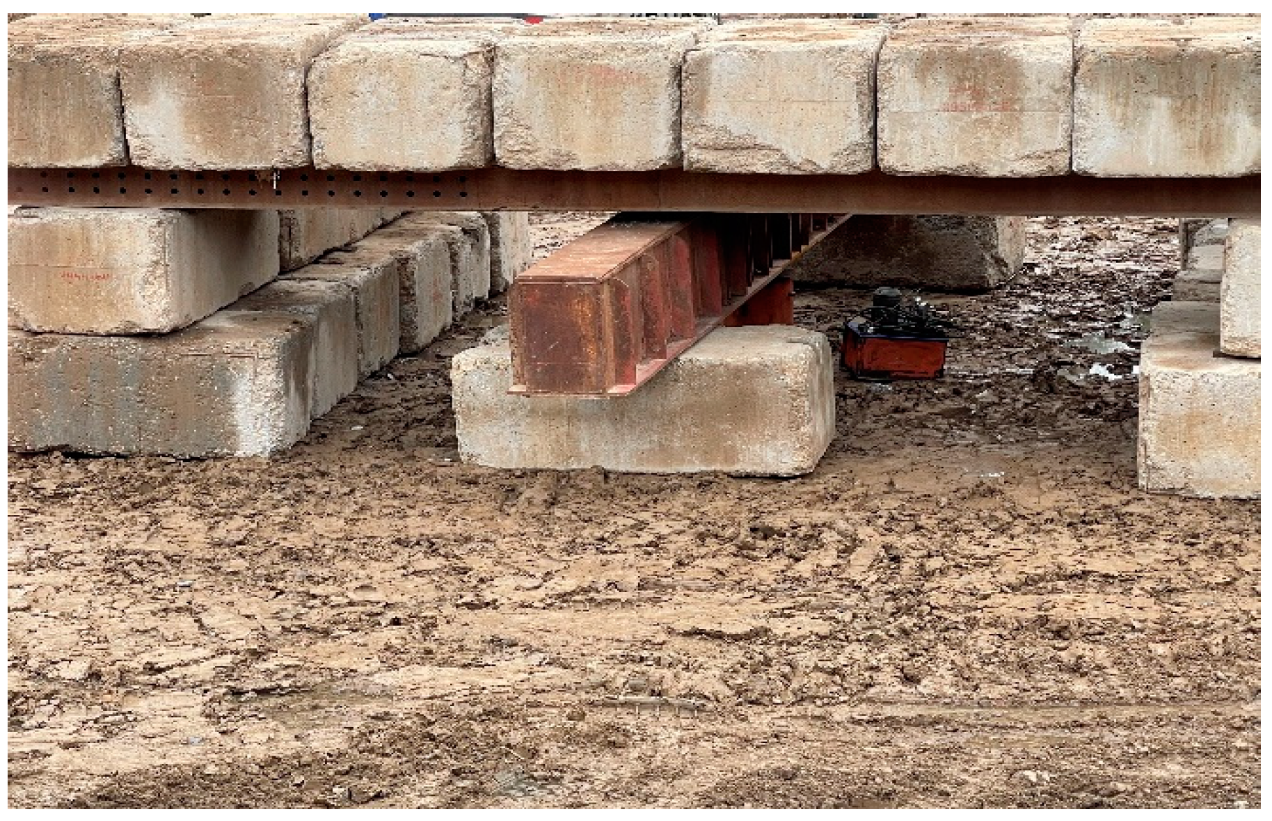
2.2. Model Test Device

The model box was made of acrylic plates with a size of 500 × 500 × 750 mm and reinforced with steel plates at a thickness around 10 mm. The model box met the requirements of strength and stiffness in the process of cyclic loading and could effectively reduce the boundary effect in the test. The schematic of the cyclic load model test is presented in Figure 1a, which consisted of the loading device, control system, measurement system, and model box. The loading device was composed of a pneumatic pump, a pressurized cylinder, an electrical proportional valve, and a gas pipe, while the control system was composed of an electrical proportional valve and a PLC control panel, and the measurement system was composed of a pressure sensor, a strain gauge, an electric displacement meter, and a dynamic strain acquisition instrument. The PLC control panel could control the voltage signal according to the test requirements of a certain law to use the pneumatic pump and cylinder to realize the loading control of the static load and dynamic load and use the electric displacement meter and dynamic strain collection instrument to collect the test data.
The test installation and distribution of the instrument components are shown in Figure 1b. After the model pile was fabricated and maintained, six groups of strain gauges were attached to the pile body, with two strain gauges in each group, which were evenly distributed on the pile body surface to guarantee the accurateness of the testing data. When our team pasted the strain gauge, the position attached to the strain gauge was polished until smoothness with sanded paper and coated with alcohol. After the evaporation of the alcohol, the strain gauge was pasted. During the pasting process, the strain gauge was squeezed to ensure that there were no bubbles between the strain gauge and the model pile. During the cyclic loading, the pile axial force, pile lateral friction, and pile–fly ash load transfer mechanism were studied. The settlement change in the CFMP fly ash composite foundation under cyclic loading was measured by an electric displacement meter. The settlement law of the composite foundation and the compression change in the fly ash around the pile were studied according to the observation results of the ground settlement deformation and accumulated settlement during the test, which were symmetrically arranged on both sides of the bearing plate.

2.3. Field Test

The fly ash accumulation area of Shangyao in Huainan city was selected for the field test, and the fly ash foundation was strengthened by CFMP. A total of six CFMP piles were arranged in the test. The pile length was 13 m, the pile diameter was 1 m, the cement content was 20%, and the pile tip bearing layer was two layers of fly ash. Test requirements: the characteristic value of the bearing capacity of the composite foundation after reinforcement was 180 kPa, and the area replacement rate was 20%. The pile load method was used for the test, and the main instrument was a JCQ503B static load test system. The field test is shown in Figure 2. The static load test results of the six CFMPS in the field test area are shown in Figure 3.
It can be seen from the figure that the development trend of the load settlement curves of the six test piles was basically the same, and they were all gentle curves with an approximate linear relationship. The settlement and stability time were normal, indicating that there was no ultimate failure state in the loading process. According to the data, the maximum loading value was up to 1600 kN, and the ultimate bearing capacity of the composite foundation was 400 kPa. Half of the ultimate load was taken as the characteristic value of the bearing capacity, so the characteristic value of composite foundation bearing capacity was 200 kPa, greater than 180 kPa, thus meeting the design requirements.

2.4. Model Pile

The indoor model test of the pile foundation is mainly through the mechanical similarity and geometrical similarity to meet the similar conditions of the pile foundation, which are determined according to the working conditions of the field test of the model tests, which simulated the actual pile length to be 13 m, with a diameter of 1 m, in combination with the indoor model test conditions. We decided to model the test of geometric similarity constants determined for 10, the model test of the pile’s length was 500 mm, the diameter of the pile was 40 mm, and the length–diameter ratio was 12.5. The boundary distance between the model pile and model box was 225 mm, while the minimum spacing ratio was greater than 5, and the pile–wall interaction could be ignored. As a fundamental part of the CFMP composite foundation, changes in the model pile strength will cast an impact on the bearing capacity of the composite foundation. Therefore, according to the research results of the fly ash strength by Zhou et al. [33,34], this was discovered after blending, according to 20% cement, 80% fly ash, and 35% water (Cement 42.5 general cement), which was poured into a customized PVC tube with a length of 50 cm, an inner diameter of 4 cm, and a wall thickness of 0.5 cm. The tube was placed in a curing room for 5 days, and then the PVC tube was cut with a miniature cutting machine. Subsequently, the model pile was removed and cured for 55 days.
The pile embedment method was utilized to embed the model 15 cm below the bottom of the pile foundation of the fly ash embankment compaction. Then, our team used a steel rule to find the position of the model pile embedment. After the completion of the pile and the filling of fly ash in time, our team fabricated a preliminary vertical compaction pile. To make the fly ash uniform and dense, each layer of the landfill of fly ash was 5 cm thick. Soil stratification was prevented by shaving the layers. The model pile was buried and a 5 cm mattress was laid.

3. Methods

3.1. Test Scheme

To investigate the impacts of the cyclic load on the bearing property of the CFMP fly ash composite foundation, the assay was divided into the static load test and the cyclic load test according to the load type.

3.1.1. Static Load Test of the CFMP Composite Foundation

Before cyclic loading, a single pile static load assay of the cement–fly ash mixing pile was implemented to determine the ultimate bearing capacity of the model pile. According to the Technical Code for Building Foundation Treatment (JGJ79-2012) [35], the indoor model test was performed after the model pile was maintained for 55 days, and the load plate with a side length of 10 cm was loaded by an air pressure pump and a pressurized cylinder. The slow maintenance load method was adopted in the experiment, and the loading grade was no less than 8. After loading at each stage, the settlement displacement was collected every 10, 10, 10, 15, 15, 15, and 30 min. When the settlement rate did not exceed 0.1 mm/h, the next level load was added, and the eventual test load reached 3000 N.

3.1.2. Cyclic Load Test of the CFMP Composite Foundation

The cyclic load is composed of the constant load and dynamic load. Qc is defined as the ultimate bearing capacity of a single pile, and Q1 denotes the constant load. Q2 denotes the dynamic load, while M = Q2/Qc represents the kinetic load ratio. During the service period, the constant load of the pile foundation was comparatively steady, whereas the kinetic load varied within a certain range. Therefore, the constant load of a single pile Q1 = 0.2 Qc and the kinetic load ratio M = 0.1, 0.2, 0.3, 0.4, 0.5, and 0.6. The continuous sinusoidal waveform loading curve was used to simulate the dynamic load received by the pile foundation. The waveform is shown in Figure 4, and the test load variation is shown in Equation (1)
Q = Q 1 + Q 2 = 0.2 Q c + M Q c sin ( w t )
where w is the loading frequency (Hz), w = 1, and t is the loading time (s).

3.2. Data Processing

The settlement curve of the CFMP composite foundation under the cyclic load test was fitted by the following Equations (2)–(5)
S N = A l n N + B
S N = C N D
S N S 0 S m a x S 0 = 1 a ( 1 + b N ) 2
S N S 0 S m a x S 0 = a l n ( 1 + N b )
where S N is the settlement value during the Nth load cycle, and S 0 is the settlement value after the initial cycle, while S m a x is the final settlement value after the 10,000th cycle.
In the vertical cyclic load test, the load value required for the unit settlement of the pile–soil system was called the pile top dynamic stiffness, represented by Kc, which reflected the capacity of the pile–soil system to bear the cyclic load to a certain extent.
    K c = 2 A 0 / p c
where A0 is the cross-sectional area of the pile body, and pc is the difference in the cyclic settlement of the pile top.
The axial force of the pile could be obtained by reading the strain gauge data pasted on the pile and converting it into the following Equation (7):
Q i = E A 0 ε i
where Qi denotes the pile shaft axial force; E is the elastic modulus of the model pile; and εi is the axial strain at the model pile i.

4. Results

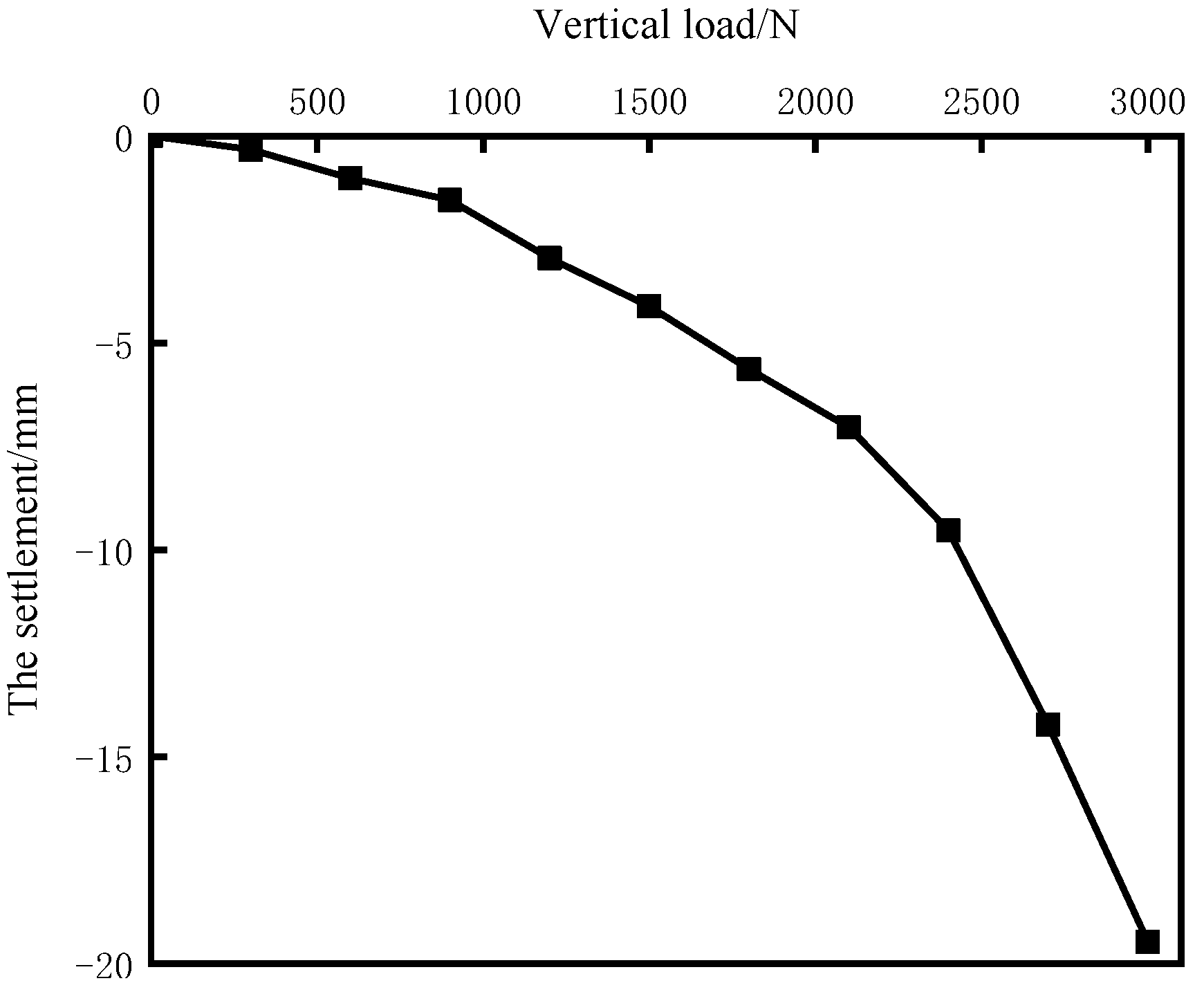
4.1. Static Load Test

According to the measured data, Figure 5 was drawn.
We discovered that the ultimate bearing capacity of the model pile was 2400 N, with the corresponding foundation settlement reaching 9.53 mm. The figure shows that the ultimate bearing capacity of the model pile was 2400 N, and the corresponding foundation settlement reached 9.53 mm. The displacement curve of the CFMP fly ash composite foundation showed an obvious inflection point, which was a steep drop-type curve. With the constant increase in the load, the settlement displacement gradually increased. When the load was in the range of 0~2100 N, the settlement of each stage was relatively stable.

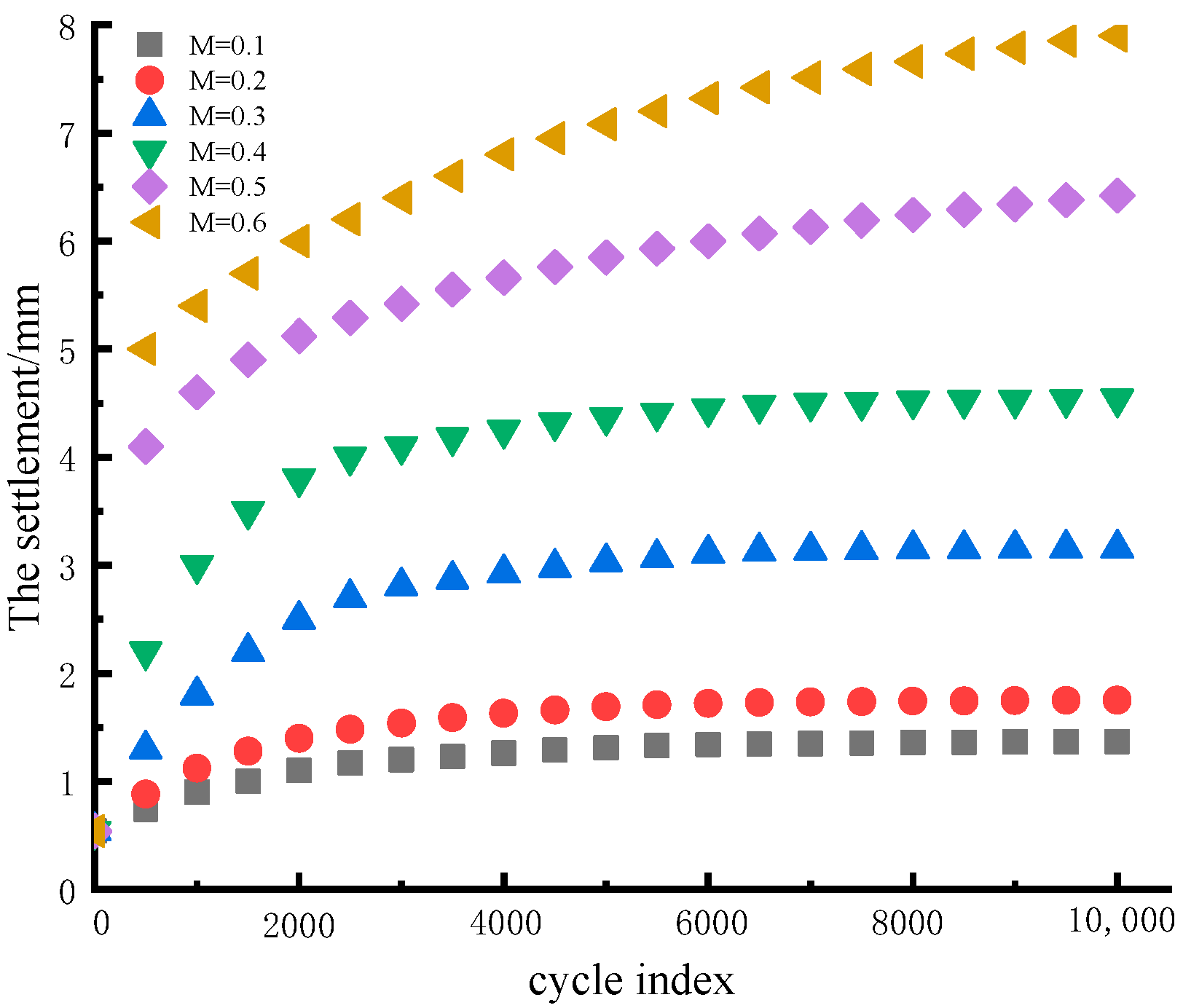
4.2. Settlement under Cyclic Loading

After the ultimate bearing capacity of the model pile was determined according to the static load test, cyclic loading tests under diverse kinetic load ratios M were performed as per the test scheme. Figure 6 presents the relationship between the pile top cumulative settlement and cycle times obtained from six groups of cyclic tests.
By virtue of the figure, we can discover that with the elevation in the quantity of cycles, the accumulative settlement of the CFMP pile top increased progressively. According to the law that the pile top settlement increases with the number of cycles, the curve can be classified as the attenuation type and destruction type, corresponding to the settlement curve of M = 0.1, 0.2, 0.3, 0.4 and M = 0.5, 0.6 in the figure, respectively. When the dynamic load ratio M ≤ 0.4, the relationship curve between the cumulative settlement and the number of cycles presented an attenuation type (i.e., when the quantity of cycles was small, the accumulative settlement grew faster, and the pile top settlement gradually exhibited a stable tendency with the elevating quantity of cycles). After a long period of vertical load, the pile–fly ash system basically displayed a stable tendency. When the kinetic load M ≥ 0.5, the relation curves presented the damage type. Namely, at the beginning of the cycle load, the pile top cumulative settlement grew faster, and after a period of cyclic loading, the settlement did not present the tendency of convergence, with a smaller growth rate increasing slowly, especially in the face of the cyclic loading peak, which was close to the ultimate bearing capacity of the CFMP cumulative settlement. Eventually, the dynamic failure of the pile foundation occurred, which should be avoided in the actual CFMP composite foundation application scenario.
At present, the development law of the pile foundation’s cumulative settlement is still elusive, as the research on the bearing features of the CFMP composite foundation under cyclic load is inadequate. Therefore, research on the settlement characteristics of the CFMP composite foundation under cyclic load is imperative for practical engineering applications. By fitting the settlement data of the CFMP fly ash composite foundation with the cyclic load, the foundation displacement in the actual project can be predicted and analyzed to judge whether the foundation bearing capacity can meet the engineering needs and provide a theoretical basis for engineering design. The settlement curves of the CFMP composite foundation under the cyclic load test in Figure 5 were fitted with S N = A l n N + B ,   S N = C N D , respectively, and their correlation coefficients were compared. The outcomes are presented in Table 3.
We can see from the fitting data that the traditional logarithmic function and the power function are not ideal for the cyclic settlement fitting of the CFMP composite foundation. Therefore, the following equation was proposed to realize improvements, the results of which are displayed in Table 4.
It can be seen from Table 4 that for the attenuation curve M ≤ 0.4, the hyperbolic equation presented a better fitting effect, whereas the logarithmic function was more suitable for the destructive curve M ≥ 0.5.

4.3. Dynamic Stiffness of Pile Top

Figure 7 presents the curve relation of the dynamic stiffness with the number of cycles under different dynamic load ratios. In the figure, K1 is the average stiffness of the initial cycle, and KN is the average stiffness of the NTH cycle.
As presented in the figure, the dynamic stiffness of the pile top was weakened to different degrees with the elevation in the quantity of cycles. At the early stage of the load cycle, the dynamic stiffness dropped rapidly, and then gradually became stable with the progress of the cycle test. Our team observed that the CFMP settlement of the composite foundation under cyclic loading was initially not steady. During the test, after a short period of transition, the dynamic stiffness was attenuated significantly, which was due to the fact that at the beginning of the cycle loading, the CFMP coordination between the pile and fly ash in the pile top settlement was unstable. Then, it gradually increased to a constant amplitude, and stiffness and friction degradation occurred in the stratum near the pile–fly ash contact surface at this stage. When the kinetic load ratio was small, the weakening in the dynamic stiffness of the pile head was more evident than that of the large kinetic load ratio.

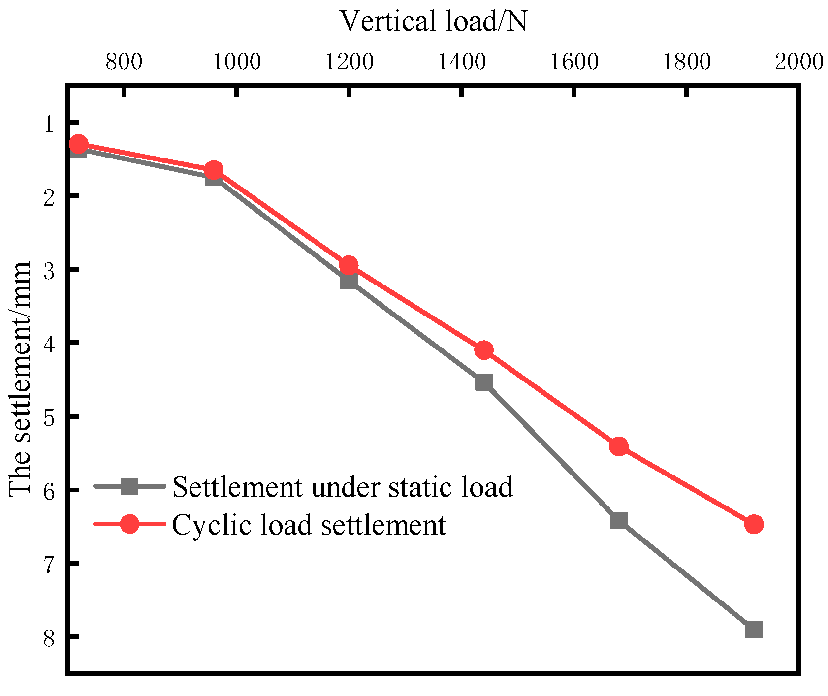
4.4. Cyclic Settlement and Static Settlement under the Same Load

According to M = 0.1, 0.2, 0.3, 0.4, 0.5 and 0.6, the final settlement cumulative value under cyclic load was compared with the settlement value via the static load assay under the identical load, as shown in Figure 8.
Our team discovered that the settlement displacement of the pile top increased parabolically with the elevation in the vertical load under the static load and cyclic load. When the vertical load was small, the difference in the settlement between them was not evident, whereas with the elevation in the load value, the difference progressively became clear. The ratio of the settlement value of the cyclic load to that of the static load under the identical vertical load was considered as the cyclic static displacement ratio α. It was found that α was between 1.05 and 1.23 under different dynamic load ratios, which was due to the limited compressive deformation and crushing degree of the fly ash stratum under static load. During cyclic loading, the pile–fly ash interface constantly produced compaction and stress concentration, so the fly ash was more prone to breakage and interpenetration between the particles, which consequently accelerated the compression deformation of the fly ash stratum at the pile end. The α–M curve was fitted, and the final equation is written as follows: y = 0.745 x 2 0.1626 x + 1.0607 (R2 = 0.983). The settlement of the cyclic load under different dynamic load ratios could be calculated based on the static load test results of this kind of equation to further facilitate the bearing capacity design of the CFMP composite foundation under cyclic load.

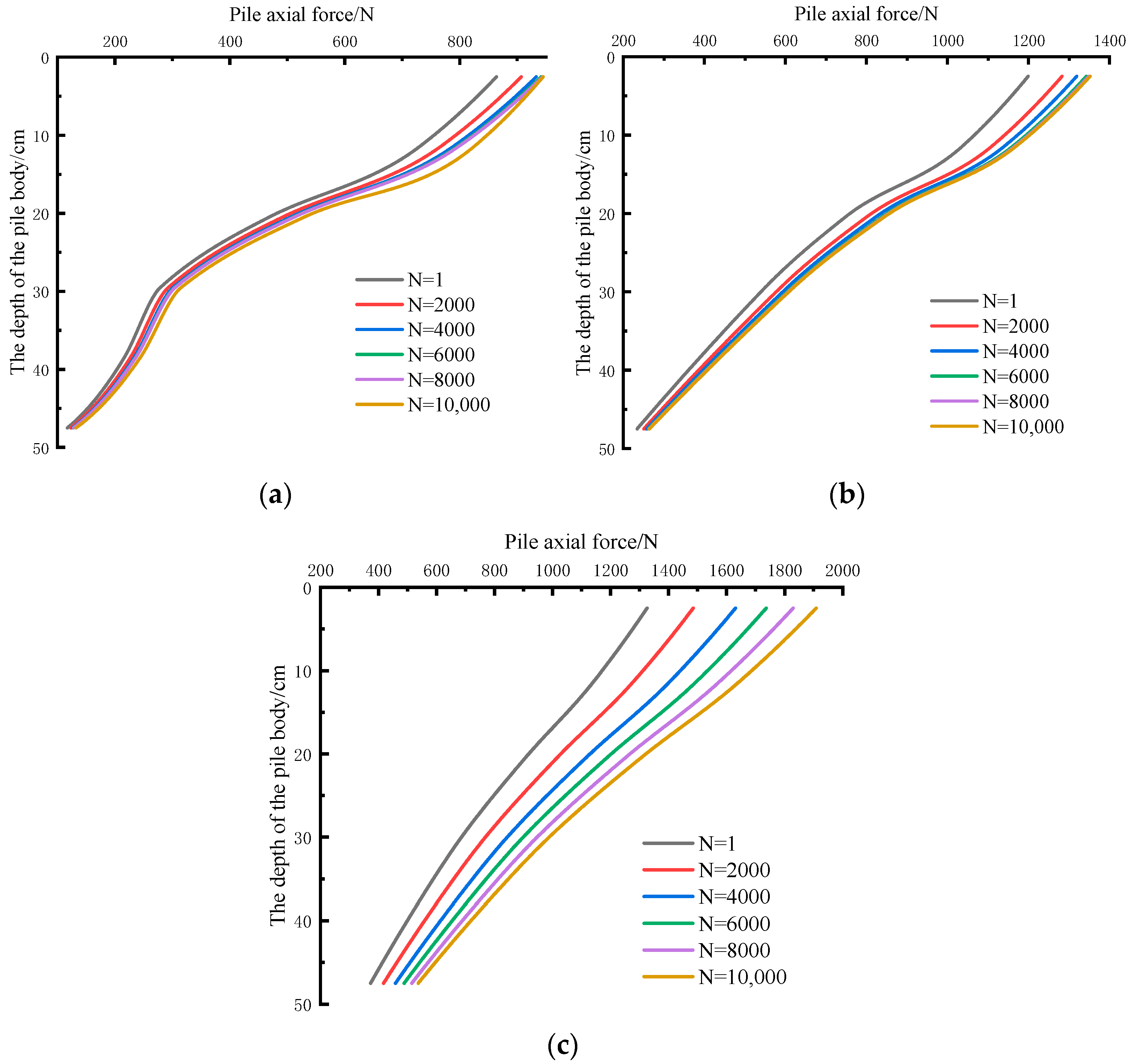
4.5. Pile Axial Force and Pile Side Friction Resistance under Cyclic Load

Here, the maximum value of the axial force in each cycle of M = 0.2, 0.4 and 0.6 was used for the analysis and research. The axial force distribution values of the pile body under different dynamic load ratios are presented in Figure 9.
We can see from the figure that the pile axial force in the first cycle was the smallest, and the pile axial force increased positively with the number of cycles when the cyclic load test progressed. In terms of the axial force growth rate corresponding to the two working conditions, the increase in the pile axial force primarily occurred in the initial stage of cyclic loading. When M = 0.2, 0.4, the 4000-time cycle of the rear axle force compared to the first circular axial force increased by 8% and 10% in the process of the subsequent loop pile axial force gradually stabilizing, this is because at the beginning of cyclic loading, the pile side of the fly ash has a compacting effect under the action of vertical load, so the pile–fly ash system slides between the smaller. As a result, the lateral friction of the pile decreased in the cycle process progressively (i.e., the axial force of the pile was increased). After a certain number of cycles, the pile–fly ash system exhibited a stable tendency, and the axial force of the pile also gradually became stabilized. When M = 0.6, the pile axial force increased by 15% after 4000 cycles. With the increase in cycles, the pile axial force still increased slowly. When the final cycle number reached 10,000, the axial force increased by 20% compared with the initial cycle, which was caused by the instability of the pile–fly ash system. If the dynamic load ratio is ≥0.4, the CFMP composite foundation will be destroyed, which should be avoided in practical engineering applications.
The CFMP, under the cyclic loading curves of the axial force of piles, to a certain extent, reflects the change in the pile side friction under the vertical load caused by the pile side friction. This gradually began to play a role as the pile axial force began to decrease, and the pile body, pile-smaller values of the relative displacement of fly ash, and side friction increased slowly with the down load transfer. The relative displacement of the pile–fly ash began to increase, and the lateral friction resistance also presented a rapid growth tendency. When it reached a certain value, the lateral friction resistance of the pile came into play, and the pile tip bearing layer also began to play a role. In the meantime, the pile tip resistance increased rapidly. Figure 10 shows the variation of pile lateral friction with the number of cycles
In the figure, Q1 is the peak value of the pile lateral friction in the initial cycle, and QNmax is the peak value of the pile lateral friction in the NTH cycle. As presented by the figure, the CFMP pile lateral friction resistance under cyclic loading was negatively correlated with the number of cycles. With the increasing number of cycles, the lateral friction resistance presented a downward trend and eventually exhibited a stable tendency. Meanwhile, the kinetic load ratio M was positively correlated with the sliding degree of the pile lateral friction resistance. The higher the kinetic load ratio, the greater the sliding degree.
As for the degradation of the pile side friction resistance, the main reason is that the fly ash, as a kind of dust material, has strong permeability. Due to the influence of the vertical cyclic load, the shear zone of the fly ash around the pile kept shrinking, which consequently caused the persistent degradation of the pile side stress. The indoor direct shear test revealed that the soil deformation was predominantly concentrated in the contact between an object’s surface and the shear zone area for this kind of strong water imbibition of fly ash dust, due to the production of curing, as the moisture content of the loads were shattered and there were no large pores, causing a strong shear effect.
To verify the impacts of the water content of the fly ash foundation on the fatigue degradation of the pile side friction, the fly ash stratums with water contents of 20%, 40%, 60% and 80% were selected to perform cyclic loading tests when M = 0.2, 0.4, and 0.6, respectively. The test results are shown in Figure 11.
As displayed in the diagram, the pile side friction with the increase in the moisture content in the fatigue degradation phenomenon was more obvious, the moisture content was low; after certain cycles, the side friction began to reduce the attenuation speed and became stable, and when the moisture content ≥60% continued to decline, there was no stable trend. When the side friction was M = 0.6, there was little degradation, and the pile–soil–fly ash system was seriously damaged, which affected the service performance of the structure of the whole composite foundation. Under diverse kinetic loading ratios of M for a moisture content ≤ 40% in the CFMP fly ash composite foundation, the pile side friction eventually stabilized the fatigue degradation, a degradation degree of 50% or less. When making the CFMP fly ash composite foundation design, the safety coefficient value should be set at 0.4. On one hand, the excessively high safety coefficient values can lead to the settlement of the composite foundation under circulating load, influencing the service state of the structure. On the other hand, if the value is too low, the difficulty in producing building materials for engineering construction will be increased. Therefore, in practical engineering applications, not only should we highlight the initial moisture content of a fly ash foundation, but we should also focus on the moisture affecting the construction and service.

5. Conclusions

This paper investigated thee CFMP fly ash foundation reinforcement under the vertical cyclic loading model test, the CFMP composite foundation under different dynamic loading ratios of subsidence displacement, the dynamic stiffness, the loop–pile head than the static displacement, the axial force of the pile, and the change rule in the pile side friction, which were studied to analyze the composite foundation settlement prediction equations along with the change of cycles. Based on the analysis of the fatigue degradation phenomenon in the test process, the influence of the water content of the fly ash foundation on fatigue degradation was verified, and the following conclusions were drawn:
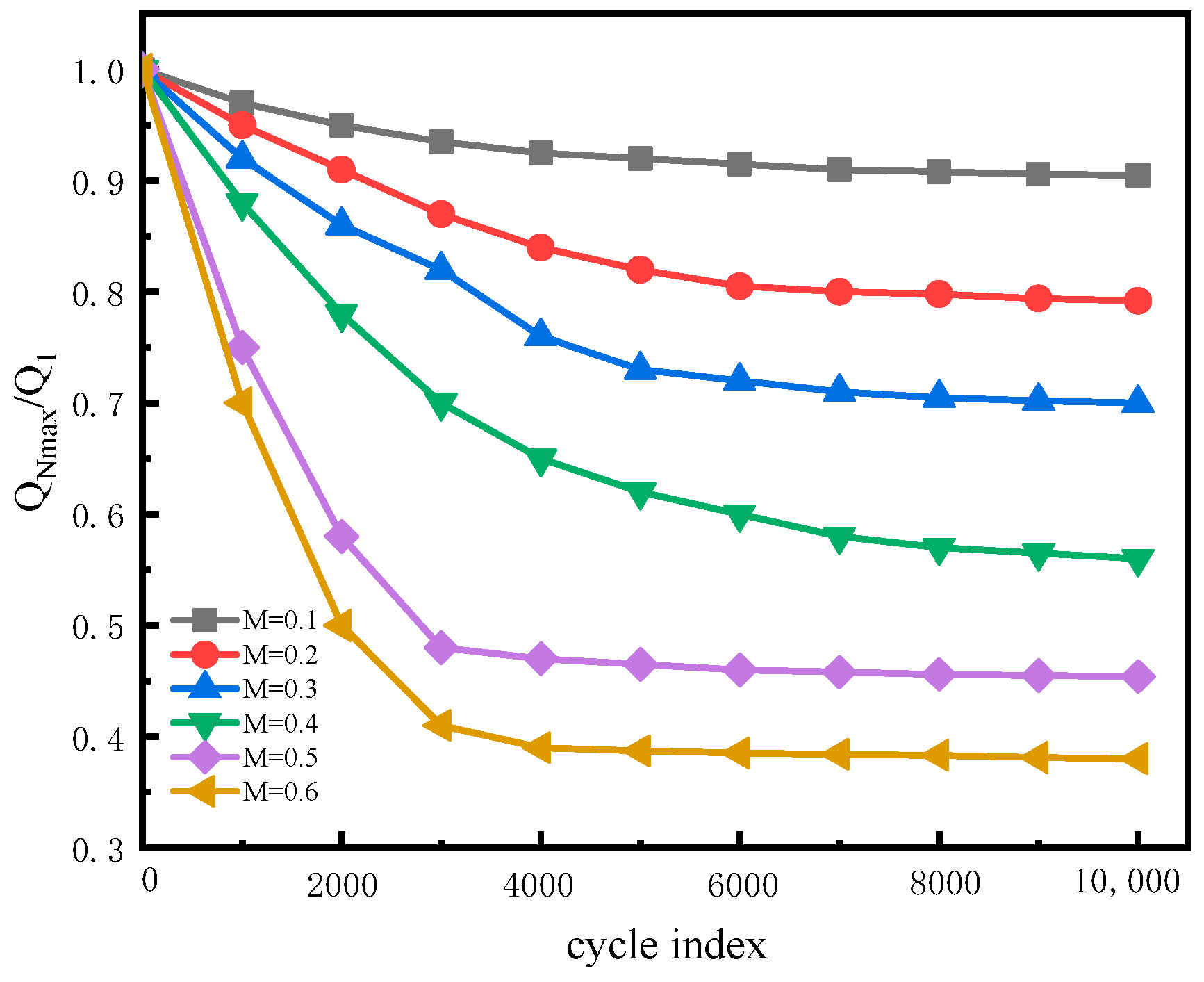
  • When the dynamic load ratio was greater than the value of the critical dynamic load ratio Mmin, the accumulated pile top settlement with the elevation of the cycle did not present the tendency of convergence, especially when the peak load was close to the ultimate bearing capacity. When the cumulative settlement grew, it eventually led to the dynamic damage of the pile foundation, with trials of the Mmin CFMP fly ash composite foundation at about 0.4.
  • By fitting the Sn–n curve of the cyclic load test and using S N S 0 S m a x S 0 = 1 a ( 1 + b N ) 2 to describe the decay curve when M ≤ 0.4, the authors discovered that S N S 0 S m a x S 0 = a l n ( 1 + N b ) was more suitable for the destructive curve when M ≥ 0.5.
  • The cyclic static displacement ratio α was between 1.05 and 1.23, and α displayed a certain correlation with the dynamic load ratio M, hence, α and M can be used in engineering. The results reveal that the static load settlement could predict the cumulative settlement of the CFMP composite foundation under the same cyclic load.
  • There was a positive correlation between the pile axial force and cycle times under cyclic load. When the dynamic load ratio was M ≤ 0.4, the axial force developed steadily and the pile–fly ash system was stable. If M > 0.4, the CFMP composite foundation will be damaged, which should be avoided in practical engineering applications.
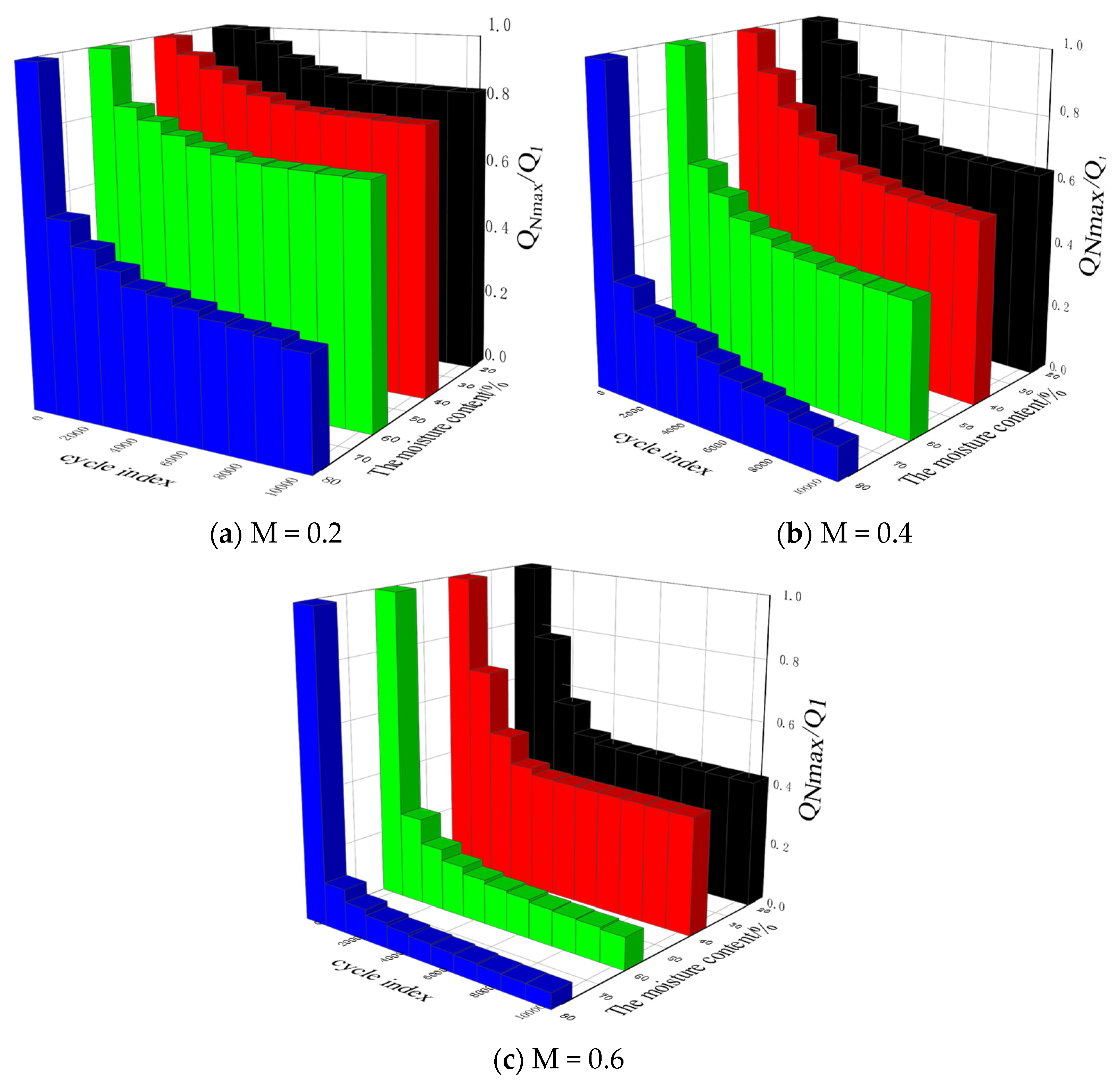
  • For a CFMP fly ash composite foundation, the level of water content exerts a fundamental impact on the fatigue degradation of the pile side friction resistance, thus affecting the bearing capacity of the composite foundation. In the course of design, the reduction in the bearing capacity that is caused by the foundation structure soaking damage should be considered, the foundation soaking should be reduced during construction, and there should be waterproof measures.
The model test results showed that compared with the traditional concrete pile composite foundation, CFMP has a good bearing performance and control deformation ability. Modifying the engineering properties of the fly ash foundation to achieve the purpose of improving the bearing capacity, critical load ratio, settlement equation, and cycle–static displacement ratio can provide theoretical support for the engineering applications of composite foundation CFMP and its design basis. Compared with the current research results on fly ash foundation, the CFMP composite foundation has obvious bearing capacity advantages, which can greatly improve the bearing capacity of the fly ash foundation, meet the engineering needs, and has good engineering application prospects.

Author Contributions

Writing—original draft preparation, writing—review and editing, H.Z.; Conceptualization, methodology, S.Z.; Validation, formal analysis, R.W.; Supervision, D.L. All authors have read and agreed to the published version of the manuscript.

Funding

This research was funded by the National Natural Science Foundation of China (42061011; 41977236); the Graduate Innovation Fund project of the Anhui University of Science and Technology in 2021 (2021CX2038) and Anhui Province Key Laboratory of Green Building and Assembly Construction, Anhui Institute of Building Research & Design, Grant NO.2022-JKYL-006.

Data Availability Statement

All data, models, and the code generated or used during the study appear in the submitted article.

Acknowledgments

The authors sincerely thank the School of Civil Engineering and Architecture, the State Key Laboratory of Mining Response and Disaster Prevention and Control in Deep Coal Mine at Anhui University of Science and Technology for providing the experimental conditions.

Conflicts of Interest

No potential conflict of interest are reported by the authors.

References

  1. Zimar, Z.; Robert, D.; Zhou, A.; Giustozzi, F.; Setunge, S.; Kodikara, J. Application of coal fly ash in pavement subgrade stabilisation: A review. J. Environ. Manag. 2022, 312, 114926. [Google Scholar] [CrossRef] [PubMed]
  2. Cheng, B.; Liu, R.; Li, X.; del Rey Castillo, E.; Chen, M.; Li, S. Effects of fly and coal bottom ash ratio on backfill material performance. Constr. Build. Mater. 2022, 319, 125831. [Google Scholar] [CrossRef]
  3. Baran, P.; Nazarko, M.; Włosińska, E.; Kanciruk, A.; Zarębska, K. Synthesis of geopolymers derived from fly ash with an addition of perlite. J. Clean. Prod. 2021, 293, 126112. [Google Scholar] [CrossRef]
  4. Fan, C.; Wang, B.; Ai, H.; Qi, Y.; Liu, Z. A comparative study on solidification/stabilization characteristics of coal fly ash-based geopolymer and Portland cement on heavy metals in MSWI fly ash. J. Clean. Prod. 2021, 319, 128790. [Google Scholar] [CrossRef]
  5. Teixeira, E.R.; Camões, A.; Branco, F.G. Synergetic effect of biomass fly ash on improvement of high-volume coal fly ash concrete properties. Constr. Build. Mater. 2022, 314, 125680. [Google Scholar] [CrossRef]
  6. Gołaszewski, J.; Ponikiewski, T.; Kostrzanowska-Siedlarz, A.; Miera, P. Technological aspects of usage of calcareous fly ash as a main constituent of cements. Period. Polytech. Civ. Eng. 2021, 65, 619–637. [Google Scholar] [CrossRef]
  7. Elahi, T.E.; Shahriar, A.R.; Islam, M.S. Engineering characteristics of compressed earth blocks stabilized with cement and fly ash. Constr. Build. Mater. 2021, 277, 122367. [Google Scholar] [CrossRef]
  8. Huseien, G.F.; Joudah, Z.H.; Khalid, N.H.; Sam, A.R.; Tahir, M.M.; Lim, N.H.; Alyousef, R.; Mirza, J. Durability performance of modified concrete incorporating fly ash and effective microorganism. Constr. Build. Mater. 2021, 267, 120947. [Google Scholar] [CrossRef]
  9. Gołaszewski, J.; Ponikiewski, T.; Kostrzanowska-Siedlarz, A.; Miera, P. The Influence of Calcareous Fly Ash on the Effectiveness of Plasticizers and Superplasticizers. Materials 2020, 13, 2245. [Google Scholar] [CrossRef]
  10. Phutthananon, C.; Jongpradist, P.; Yensri, P.; Jamsawang, P. Dependence of ultimate bearing capacity and failure behavior of T-shaped deep cement mixing piles on enlarged cap shape and pile strength. Comput. Geotech. 2018, 97, 27–41. [Google Scholar] [CrossRef]
  11. Raongjant, W.; Jing, M. Field testing of stiffened deep cement mixing piles under lateral cyclic loading. Earthq. Eng. Eng. Vib. 2013, 12, 261–265. [Google Scholar] [CrossRef]
  12. Petersen, I.F. Blending in circular and longitudinal mixing piles. Chemom. Intell. Lab. Syst. 2004, 74, 135–141. [Google Scholar] [CrossRef]
  13. Lu, X.; Mengen, S.; Wang, P. Numerical simulation of the composite foundation of cement soil mixing piles using FLAC3D. Clust. Comput. 2019, 22, 7965–7974. [Google Scholar] [CrossRef]
  14. Zhou, S.; Zhang, Y.; Xu, Y.; Li, D. Research on the dynamic mechanical properties of stabilized cement-fly ash samples. J. Vib. Shock. 2021, 40, 119–126. [Google Scholar]
  15. Zhou, S.Q.; Zhou, D.W.; Zhang, Y.F.; Wang, W.J. Study on physical-mechanical properties and microstructure of expansive soil stabilized with fly ash and lime. Adv. Civ. Eng. 2019, 2019, 4693757. [Google Scholar] [CrossRef]
  16. Zhang, Y. Experimental study on mechanical properties of modified fly ash formation materials. Anhui Univ. Sci. Technol. 2021. [Google Scholar] [CrossRef]
  17. Qu, L.M.; Ding, X.M.; Wu, C.R.; Long, Y.H.; Yang, J.C. Effects of topography on dynamic responses of single piles under vertical cyclic loading. J. Mt. Sci. 2020, 17, 230–243. [Google Scholar] [CrossRef]
  18. Khidri, M.; Deng, L. Field axial cyclic loading tests of screw micropiles in cohesionless soil. Soil Dyn. Earthq. Eng. 2021, 143, 106601. [Google Scholar] [CrossRef]
  19. Thomassen, K.; Andersen, L.V.; Ibsen, L.B. Axial Cyclic Loading Tests on Pile Segments in Sand. Int. J. Offshore Polar Eng. 2016, 26, 348–354. [Google Scholar] [CrossRef]
  20. Lu, Y.; Liu, H.; Zheng, C.; Ding, X. Experimental Study on the Behavior of X-Section Pile Subjected to Cyclic Axial Load in Sand. Shock. Vib. 2017, 2017, 2431813. [Google Scholar] [CrossRef] [Green Version]
  21. Pham, H.V.; Dias, D. 3D Numerical Modeling of a Piled Embankment under Cyclic Loading. Int. J. Geomech. 2019, 19, 04019010. [Google Scholar] [CrossRef]
  22. Zhu, S.; Chen, C.; Cai, H.; Mao, F. Analytical modeling for the load-transfer behavior of stiffened deep cement mixing (SDCM) pile with rigid cap in layer soils. Comput. Geotech. 2022, 144, 104618. [Google Scholar] [CrossRef]
  23. Srijaroen, C.; Hoy, M.; Horpibulsuk, S.; Rachan, R.; Arulrajah, A. Soil–Cement Screw Pile: Alternative Pile for Low- and Medium-Rise Buildings in Soft Bangkok Clay. J. Constr. Eng. Manag. 2021, 147, 04020173. [Google Scholar] [CrossRef]
  24. Wu, Y.; Fu, L.; Wu, W.; Cao, Y.; Zhou, X. Nonlinear Stress Analysis of Flexible Pile Composite Foundation by Energy Method. Adv. Mater. Sci. Eng. 2018, 2018, 8176398. [Google Scholar] [CrossRef] [Green Version]
  25. Bai, S.G.; Hou, Y.F.; Zhang, H.R. Experimental study on influence factors for permanent settlement of composite ground with flexible piles under cyclic loadings. Chin. J. Geotech. Eng. 2010, 32, 1309–1313. [Google Scholar]
  26. Bai, S.G.; Hou, Y.F.; Zhang, H.R. Analysis of critical cyclic stress ratio and permanent deformation of soil-soil pile composite foundation under cyclic loading. Chin. J. Geotech. Eng. 2006, 01, 84–87. [Google Scholar]
  27. Bai, S.G.; Hou, Y.F.; Zhang, H.R.; Li, Z.Q. Model test of soil-soil pile composite foundation under cyclic loading. Rock Soil Mech. 2006, 27, 1017–1020. [Google Scholar]
  28. Brown, S.F. Soil mechanics in pavement engineering. Geotechnique 1996, 46, 383–425. [Google Scholar] [CrossRef] [Green Version]
  29. Yang, L.C.; Guo, Q.H.; Zhou, S.H.; Wang, B.L.; Gao, Q. Experimental study on bearing and deformation characteristics of high-speed railway bridge piles under long-term axial cyclic loading. Chin. J. Rock Mech. Eng. 2005, 13, 2362–2368. [Google Scholar]
  30. Huang, Y.; Jiong, B.A.; Guo-ming, Z.H. Model tests on settlement of a single pile in saturated sand under unilateral cyclic loading. Chin. J. Geotech. Eng. 2009, 31, 1440–1444. [Google Scholar]
  31. Zhu, B.; Ren, Y.; Chen, R.; Chen, Y.; Wang, Z. Model test on bearing capacity and accumulated settlement of single pile subjected to axial cyclic loading. Chin. J. Geotech. Eng. 2009, 31, 186–193. [Google Scholar]
  32. Wang, S.; Lei, X.; Meng, Q.; Xu, J.; Wang, M.; Guo, W. Model tests of single pile vertical cyclic loading in calcareous sand. Mar. Georesour. Geotechnol. 2021, 39, 670–681. [Google Scholar] [CrossRef]
  33. Shengquan, Z.; Yongfei, Z.; Dawei, Z.; Weijian, W.; Zhaibang, K.; Halder, S. Fly ash foundation reinforced by cement-soil mixing piles. Dyna—Ing. E Ind. 2020, 5, 95. [Google Scholar] [CrossRef] [Green Version]
  34. Zhou, S.; Zhang, Y.; Zhou, D.; Wang, W.; Li, D.; Ke, Z. Experimental Study on Mechanical Properties of Fly Ash Stabilized with Cement. Adv. Civ. Eng. 2020, 2020, 6410246. [Google Scholar] [CrossRef]
  35. JGJ 79-2012; Technical Code for Foundation Treatment of Buildings: Beijing, China, 2012.
Figure 1. Diagram of the CFMP fly ash composite foundation model test. (a) Schematic diagram of model test layout; (b) Model test instrument layout; (c) Model test site diagram.
Processes 10 01117 g001
Figure 2. The field static load test drawing.
Processes 10 01117 g002
Figure 3. The field static load–displacement curve.
Processes 10 01117 g003
Figure 4. The waveform of the cyclic load test.
Processes 10 01117 g004
Figure 5. The settlement curve of the CFMP fly ash composite foundation under static load.
Processes 10 01117 g005
Figure 6. The CFMP fly ash composite foundation cyclic load settlement diagram.
Processes 10 01117 g006
Figure 7. The dynamic stiffness curve with the number of cycles under different dynamic load ratios.
Processes 10 01117 g007
Figure 8. The cyclic–static displacement ratio curve.
Processes 10 01117 g008
Figure 9. The axial force of the pile under cyclic load changes with the number of cycles. (a) M = 0.2; (b) M = 0.4; (c) M = 0.6.
Processes 10 01117 g009
Figure 10. The variation curve of the pile side friction resistance with the cycle times.
Processes 10 01117 g010
Figure 11. The variation in the pile lateral friction with the number of cycles under different water contents. (a) M = 0.2; (b) M = 0.4; (c) M = 0.6.
Processes 10 01117 g011
Table 1. The chemical properties of fly ash.
Chemical ComponentSiO2Al2O3Fe2O3CaOK2OTiO2SO3Loss on Ignition
The percentage (%)54.5730.146.053.881.661.490.931.28
Table 2. The physical properties of fly ash.
Basic IndexMoisture ContentNatural DensitySpecific GravityDry DensityPore RatioSaturabilityLiquid Limit
The average40% 14.3   KN / m 3 2.22 9.4   KN / m 3 1.4276.548.9
Table 3. The   S N N conventional fitting curve parameters.
M
S N = A l n N + B
S N = C N D
ABThe Correlation Coefficient: R12CDThe Correlation Coefficient: R22
0.10.21240.53280.92420.23930.19580.9384
0.20.28990.83290.94390.26410.21320.9201
0.30.6062.22430.93140.3060.26420.8789
0.40.71811.84680.92210.73480.20580.8687
0.50.78670.84230.89811.65640.14780.8987
0.61.05921.91930.88241.74930.16380.8933
Table 4. The S N N fitting curve parameters.
M
S N S 0 S m a x S 0 = 1 a ( 1 + b N ) 2
S N S 0 S m a x S 0 = a l n ( 1 + N b )
ABThe Correlation Coefficient: R12CDThe Correlation Coefficient: R22
0.11.283855.4319 × 1040.987690.23619106.671090.91664
0.21.270026.03051 × 1040.998240.24736133.514980.94039
0.31.351966.96906 × 1040.979490.23619106.671090.91664
0.41.138037.62185 × 1040.991710.1800828.380370.91425
0.50.524422.84405 × 1040.974060.134235.933350.99896
0.60.53512.48918 × 1040.953380.14510.709550.98209
Publisher’s Note: MDPI stays neutral with regard to jurisdictional claims in published maps and institutional affiliations.

