Article

Exergy Analysis of Reactive Distillation Coupled with High-Pressure Column for the Synthesis of Dimethyl Carbonate

by
Mathkar A. Alharthi
Department of Chemical Engineering, College of Engineering at Yanbu, Taibah University, Yanbu Al-Bahr 41911, Saudi Arabia
Processes 2022, 10(6), 1219; https://doi.org/10.3390/pr10061219
Submission received: 19 May 2022 / Revised: 11 June 2022 / Accepted: 16 June 2022 / Published: 18 June 2022
(This article belongs to the Section Separation Processes)

Abstract

:
In this article, the Dimethyl Carbonate (DMC) synthesis process was investigated thermodynamically based on a well-optimized DMC system for a developed configuration, according to a real industrial plant, presented by Huang et al. Exergy analysis was performed using ProSimPlus software as an efficient process modeling and simulation environment that is uniquely capable of exergy balance computations. The key operational variables such as the reflux ratio ( R r ), feed temperatures, and feed tray location were varied to explore their impact on the total irreversibilities, global intrinsic efficiency, and DMC purity. The influence of the high pressure (HP) column reflux ratio was the most effective parameter on the exergy destruction and DMC purity, which also significantly increased the duties of the HP column reboiler and condenser. The steady state results are reported in comparison with those found in the literature, and an excellent match is shown between them.

1. Introduction

Dimethyl Carbonate (DMC) is considered a green chemical product, because it is decomposable and naturally biodegradable in the environment, a nontoxic solvent, and an alternative to some toxic ketones such as methyl isobutyl, methyl ethyl, and many other ketones [1]. Another toxic oxygenate chemical, methyl tert-butyl ether (MTBE), which is used as a fuel additive, can be substituted by DMC. The chemical nature of DMC raises its classification as a potential replacement to the very toxic methylation and carbonation reagents (dimethyl sulfate, phosgene, and methyl halides), because the molecular structure of DMC has the required functional groups for methylation and carbonation reactions [2]. Another interesting application is to use DMC as a solvent for the battery electrolyte and pharmaceutical industries [3].
Today, DMC can be produced via an environmentally friendly process starting from carbon dioxide (CO2), a renewable raw material, which is reacted with ethylene oxide (EO) to produce ethylene carbonate (EC); then, the transesterification reaction of EC with methanol (MeOH) is mainly used to synthesize dimethyl carbonate [4]. However, another path is possible by using propylene oxide instead of EO to yield propylene carbonate (PC) as alternative to EC, so that the transesterification reaction can be carried out using PC with MeOH, which is more feasible route toward enhancing the PC conversion while producing both DMC with higher selectivity and propylene glycol (PG) as a secondary product [5]. On the other hand, the thermodynamic equilibrium is a well-known problem causing a slow rate of DMC production during the transesterification process; therefore, to overcome the thermodynamic equilibrium limitations of the transesterification reaction, reactive distillation (RD) technology is used to carry out the DMC synthesis process [6]. In this process, the improvement in the DMC yield would be enabled due to the continuous removing of the most volatile components (azeotropic mixture of DMC and MeOH) from the top of the RD column. Consequently, the azeotropic mixture of DMC and MeOH must be treated using special separation techniques; either pressure-swing distillation or extractive distillation can be used [7]. A system of a reactive distillation column coupled with high-pressure distillation is considered in the current work as a novel procedure for the synthesis of DMC using the transesterification reaction of PC with MeOH. The configuration of this system of DMC coupled columns was investigated elsewhere showing a better performance when compared with the original experimental plant of three columns [3]. To achieve the optimal operation conditions for the coupled columns plant, an optimization study was conducted later based on the total annual cost (TAC) as an objective function [8]. Although an optimization tool predicts the optimal operational conditions, the thermodynamic efficiency is still the appropriate method for the available energy analysis. The available energy (or exergy) is a function of the material at the steady-state conditions, such as the system temperature, the enthalpy, and the material entropy, which is used to measure the thermodynamic efficiency [9]. Since energy conservation becomes a priority in every aspect and most importantly in the chemical plant industries, the exergy analysis based on the first and second laws is adopted for the DMC system under study. The first law of thermodynamics is a fundamental concept of energy conservation, while the second law of thermodynamics serves toward understanding the quality of energy [10]. The exergy balance is a result of both the first and second law of thermodynamics that needs engineering sense for a useful analysis [11]. The efficiency of distillation depends on the optimal enhancement of the mixing and interfacial transport phenomena, which are intrinsically irreversible processes and cause entropy generation. However, the management of the destroyed exergy in the reactive and non-reactive separation systems relies on minimizing both the irreversibility and entropy generation. Therefore, the lost energy is best harvested during the equilibrium process before reaching some desired dead state. The contribution of this study is as follows:
  • A proposed DMC system configuration presented by the Huang group [3,8] was simulated using ProSimPlus software and critically investigated from a thermodynamic point of view.
  • The system was also solved using Aspen Plus for the comparison purpose of a steady-state simulation; however, ProSimPlus was used mainly in this work, because it is still uniquely capable of thermodynamic analysis, especially the exergy balance analysis.
  • An exergy analysis was performed for the overall DMC system to determine the irreversibilities (or exergy destruction) and exergy efficiencies while keeping the DMC product as its desired specifications.
  • A wide range of parametric study was conducted via figuring out the effect of the main operational variables of the DMC plant on the irreversibilities, exergy efficiency, and DMC purity.

2. Process System Modeling and Simulation

Distillation is the main technology used for chemical separation processes. The transport phenomena play a crucial role in understanding the separation process carried out in distillation; further, the modeling of this process is complex from a mathematical point of view. The complexity is further increased in the case of a reactive distillation unit due to the simultaneous reaction and separation involved in one unit. In the current study, Aspen Plus was used to simulate Huang’s proposed system presented in the literature [3,8]. On the other hand, the ProSimPlus software was used to simulate this system for the exergy analysis. Both software environments showed excellent agreement in terms of the steady-state simulation, as shown in Figure 1 and Figure 2. The thermodynamics methods used in ProSimPlus were the universal quasi-chemical (UNIQUAQ) ProSim and perfect gas models with the same binary parameters as were used in the main reference work [3,8], where UNIQUAC and Redlich-Kwong (RK) were said to be used for the liquid and gas phases, respectively. However, to reproduce the results as presented in Huang’s work, it should be emphasized here that the perfect gas model had to be used to account for the vapor phase.

2.1. Chemical Reaction Rate

The chemical reaction of DMC production is defined as the transesterification of one molecule of the PC to be reacted with two molecules of MeOH to produce DMC and PG, in the presence of sodium methoxide as a catalyst, according to the following reversible reaction:
PC + 2 MeOH DMC + PG
The total reaction rate on a specific tray is a function of the reaction volume and concentrations in the liquid phase. Both forward and backward rate constants of the above reaction are based on the Arrhenius model, which is a function of the reaction volume temperature. The catalyst concentration was not considered in the simulation due to its very low values (0.15 to 0.3 wt%) [3]. The kinetics were applied as reported by Huang [3,8]:
r = k f C P C C M e O H k b C D M C C P G C M e O H
k f = 16551.8   e x p ( 41373.5 R T )
k b = 19254.75   e x p ( 28285.5 R T )
where r is the reaction rate of the PC  ( mol · L 1 · min 1 ) , C i is the concentration of the i component ( mol · L 1 ) , R is the gas constant ( J · mol 1 · K 1 ) , and T is the temperature ( K ) .

2.2. Phase Equilibria Models

The vapor–liquid equilibrium (VLE) for the DMC quaternary system involves a binary azeotrope of DMC/MeOH to end with a complex chemical system that requires efficient models able to estimate the required parameters during simulation. The UNIQUAQ model parameters used in the current simulation was such as those presented in the literature [8]. The UNIQUAQ model is suitable in the case of a nonideal mixture for the liquid phase to predict the activity coefficients required for the VLE calculations; the state equation of a perfect gas model was used for the vapor phase. To assure the quality of the VLE model estimations, they were used to determine the boiling points of the pure components, as listed in Table 1; in addition, the azeotrope compositions were calculated and compared with an experimental data, as shown in Table 2. Moreover, in this study, Table 3 presents a comparison between the ProSimPlus and Aspen Plus azeotrope calculations.

2.3. Thermodynamic Analysis

Generally, thermodynamic analysis is described based on four fundamental equations: the material balance equation, energy balance equation, entropy generation equation, and exergy balance equation [10]. To carry out these principal equations for each unit, the ambient conditions were taken as a reference state. Taking the steady-state condition into consideration, the general mathematical forms of material, energy, entropy, and exergy equations were simplified, respectively, as follows:
i n m ˙ i n = o u t m ˙ o u t
Q ˙ i n + W ˙ i n + i n ( m ˙ h ) i n = Q ˙ o u t + W ˙ o u t + o u t ( m ˙ h ) o u t
S ˙ g e n + i n m ˙ i n S i n + k ( Q ˙ k T k ) = o u t m ˙ o u t S o u t
i n [ E ˙ x + E ˙ x Q + E ˙ x W ] i n = E ˙ x d + o u t [ E ˙ x + E ˙ x Q + E ˙ x W ] o u t
Here, m ˙ is the mass flow rate ( kg / s ) , Q ˙ is the rate of heat ( kW ) , W ˙ is the rate of work ( kW ) , h is the specific enthalpy ( kJ / kg ) , S ˙ g e n is the rate of generated entropy ( kW / K ) , S is the entropy ( kJ / K ) , E ˙ x is the total rate of exergy ( kW ) , and E ˙ x d is the rate of destructed exergy ( kW ) . Equations (1) and (2) present the fact that both mass and energy are conserved quantities during the plant operation. On the other hand, the entropy generation and the exergy destruction within the processes are determined using Equations (3) and (4), respectively. The total rate of exergy ( E ˙ x ) can be defined as
E ˙ x = m ˙   e x
where e x is the total specific exergy consisting of physical exergy ( e x p h ), chemical exergy ( e x c h ), exergy due to kinetic energy ( e x k ), and exergy due to potential energy ( e x p ). By ignoring the changes in the potential and kinetic energy in the system, the exergies due to kinetic and potential energies are zero. Therefore, the total specific exergy is formulated to be
e x = e x p h + e x c h
where
e x p h = h T 0 S
and
e x c h = i x i   e c h , i 0 + R T 0 i x i   ln ( γ i x i )
Here, x i is the mole fraction of component i in the mixture, e c h , i 0 is the standard chemical exergy of component ( kg / kmole ) , R is the universal gas constant ( kJ / kmole · K ) , and T 0 is the atmospheric temperature ( K ) . The exergy analysis is one of the thermodynamic analysis tools applied to evaluate energy efficiency. The exergy is defined as the maximum quantity of work obtained from a process during the state change of the system from some initial state to the reference equilibrium state [9]. The maximum quantity of exergy is possible when the condition of a reversible process is satisfied. The exergy can be destroyed as stated by the second law of thermodynamics; so, efficient energy management is always required to minimize the exergy loss. The main causes of exergy loss are the irreversibility inside a chemical process and the unused amount of an exergy outside the process.

2.4. Process System Simulation

Using the ProSimPlus software, the DMC plant flowsheet was simulated as illustrated in Figure 1. The ProSimPlus is uniquely capable of performing energy efficiency calculations compared with other environments of process and modeling simulation. The computation of all exergy types is possible in addition to other steady-state calculations, such as mass and energy balances. All necessary data for the simulation environment are depicted in Figure 1. The data used in this study were adopted from the previous studies presented by Huang [3,8], who carried out the simulation using Aspen Plus software. Table 4 shows the data used for the original, optimal, and current simulations, where NF1 was the location of the (PC + MeOH) mixture feed, NF2 was the location of the MeOH feed, NFR was the location of the recycle stream feed, and NF was the location of the HP column feed. To validate the results, both ProSimPlus and Aspen Plus were used in the current work showing the required agreement.

3. Results and Discussion

A parametric study was performed from a thermodynamic point of view for an optimized DMC process that was based on a novel developed procedure for a real industrial plant [3,8]. This optimized work produced optimal operational parameters, as listed in Table 4. In this study, a number of operational variables were selected for exergy analysis of the DMC process including the reflux ratio for both RD and HP columns. Moreover, the feed temperature and feed tray location of the HP column were presented, reflecting a major effect on the DMC process plant.

3.1. RD Reflux Ratio

The results of the global irreversibility and DMC purity for different values of the RD reflux ratio are shown in Figure 3, where it is noticed that both parameters increased as the reflux ratio increased. The two curves showed gradual increases until reaching the critical points, which were at the optimal reflux ratio (0.87), as presented in Table 4. An important indication from this behavior is related to the quality of the 0.87 optimized reflux ratio; so, improvements should not move away from this optimal value depending on the required level of purity. Lowering the irreversibility is associated with keeping the chemical reaction thermodynamically closer to equilibrium; however, the production of DMC still requires shifting the reaction toward the DMC side, which is a source of irreversibility. Since the DMC reaction is exothermic [13,14], carrying out the reaction at higher temperatures could lower the irreversibility, although, conventionally, the exothermic reaction should be controlled by cooling to reduce the temperature [11]. On the other hand, the duties of the RD reboiler and condenser were constant and not affected by the change in the RD reflux ratio.

3.2. HP Reflux Ratio

The results of the variation in the HP column reflux ratio were more effective on the global irreversibilities and associated with a major change in the reboiler and condenser duties of the HP column. Figure 4 shows the negative relationship between the global irreversibilities and the exergy efficiency, which is true according to the definition of exergy efficiency. Moreover, a similar negative relation between the global intrinsic exergy efficiency and DMC purity is depicted in Figure 5. As shown in Figure 6, the HP column reboiler and condenser duties were proportionally raised as the global irreversibilities rose. The main exergy destruction in the HP column was due to the high pressure that must be used to separate the azeotrope mixture of MeOH and DMC. Other causes of exergy irreversibilities came from the transport phenomena within the column during the separation process. Therefore, this exergy loss can be controlled by selecting the appropriate reflux ratio based on the required DMC purity.

3.3. HP Feed Temperature

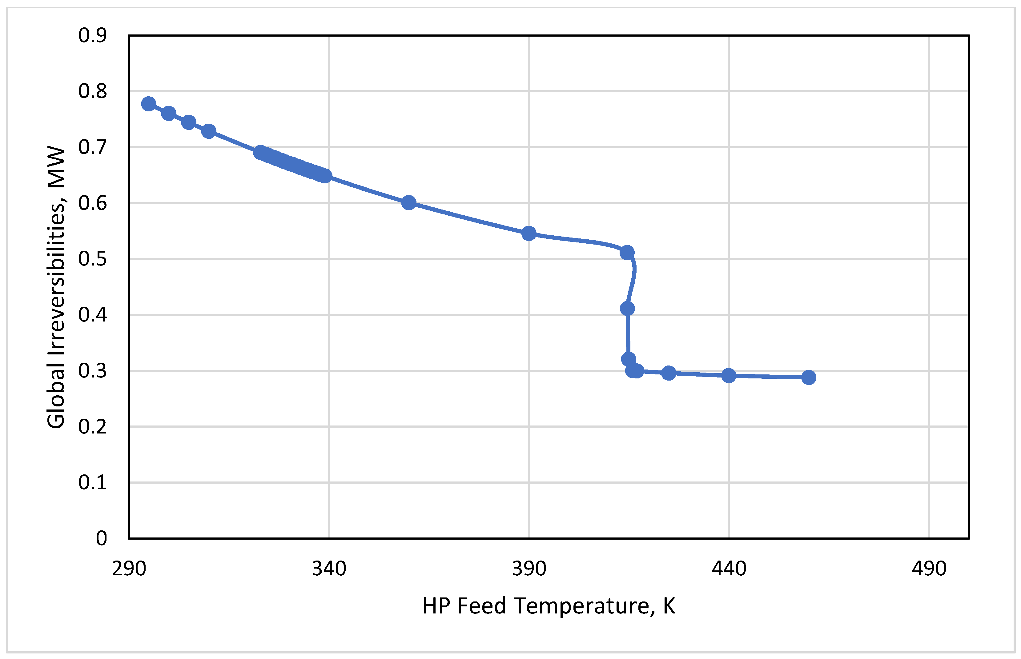
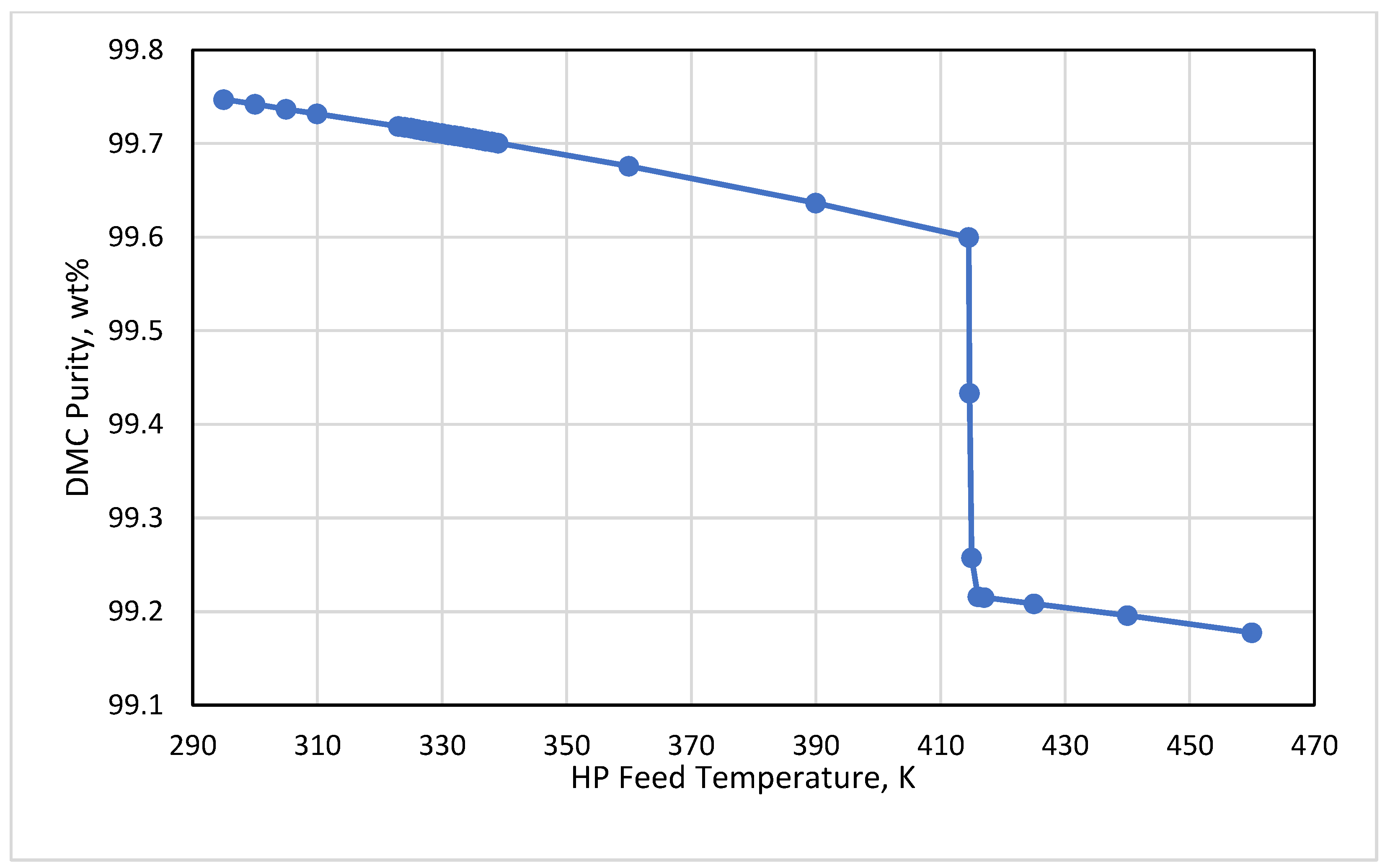
The feed temperature of the HP column at the optimal feed tray 33 showed a major influence on the global irreversibilities, as shown in Figure 7. A gradual reduction in the global irreversibilities was observed as the HP feed temperature increased from 295 K to 460 K, while keeping the feed pressure constant at 1.12 MPa. This reduction was almost constant until reaching the bubble point of the feed mixture at about 414.6 K. After the bubble point, a vertical drop in the global irreversibilities occurred until above 416 K, where beyond this temperature, the global irreversibilities became almost steady at the value of 0.29 MW. A similar trend was observed when plotting the HP feed temperature versus the DMC purity, as illustrated in Figure 8. However, the effect on the purity was very slow from 99.75 wt% until 99.18 wt% for the same range of temperatures from 295 K to 460 K. The same behavior was observed on the reboiler duty of the HP distillation, which was reduced as the feed temperature increased. Figure 9 explains the reboiler duty behavior showing sharp a reduction after the bubble point starting from 6.36 MW to 3.43 MW as the temperature increased from 414.6 K to 417 K, respectively. Therefore, manipulating the HP feed temperature is of high importance to minimize both the HP reboiler heat duty and the global irreversibilities leading to the optimal energy consumption for the required DMC specifications.

3.4. HP Feed Tray

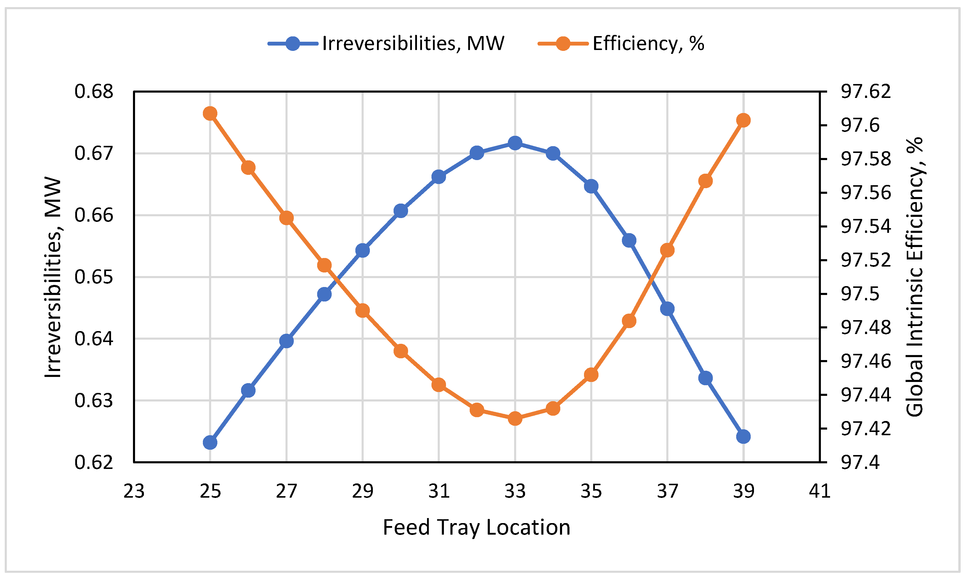
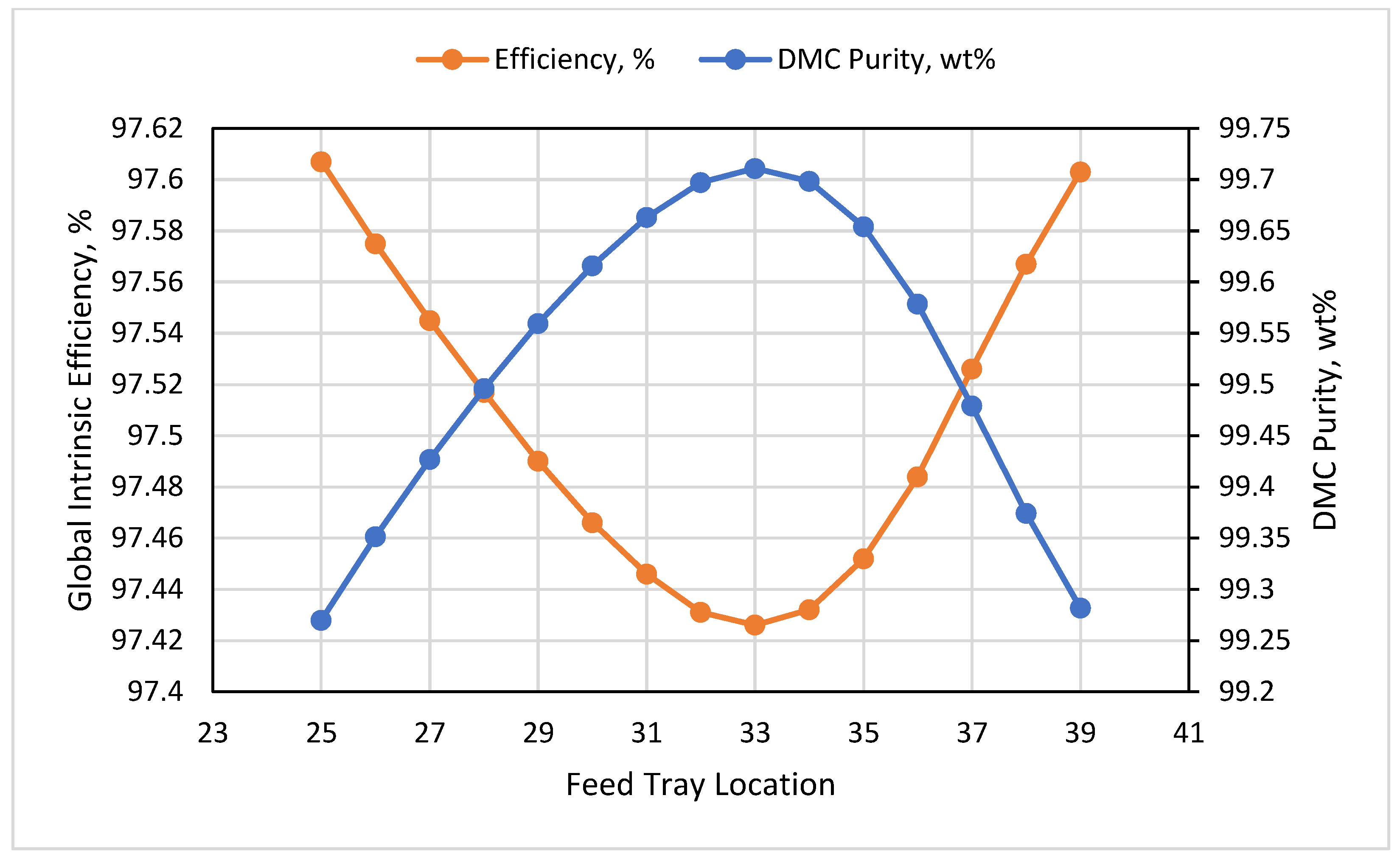
Another interesting parameter affecting the exergy of the DMC system was the feed tray of the HP column. As can be seen in Figure 10, the optimality proof of tray 33 was clearly drawn with the maximum value of global irreversibilities at 0.67 MW and the minimum value of global intrinsic efficiency at 97.43%. Moreover, the maximum DMC purity was determined to be 99.7 wt% at tray 33, as shown in Figure 11. The simulation runs showed no effect of the HP feed tray on the reboiler and condenser duties of both columns. Careful tradeoff between energy consumption and DMC purity could be implemented to manage the exergy destruction via an appropriate tray location of the HP feed.

3.5. RD Feed Temperature

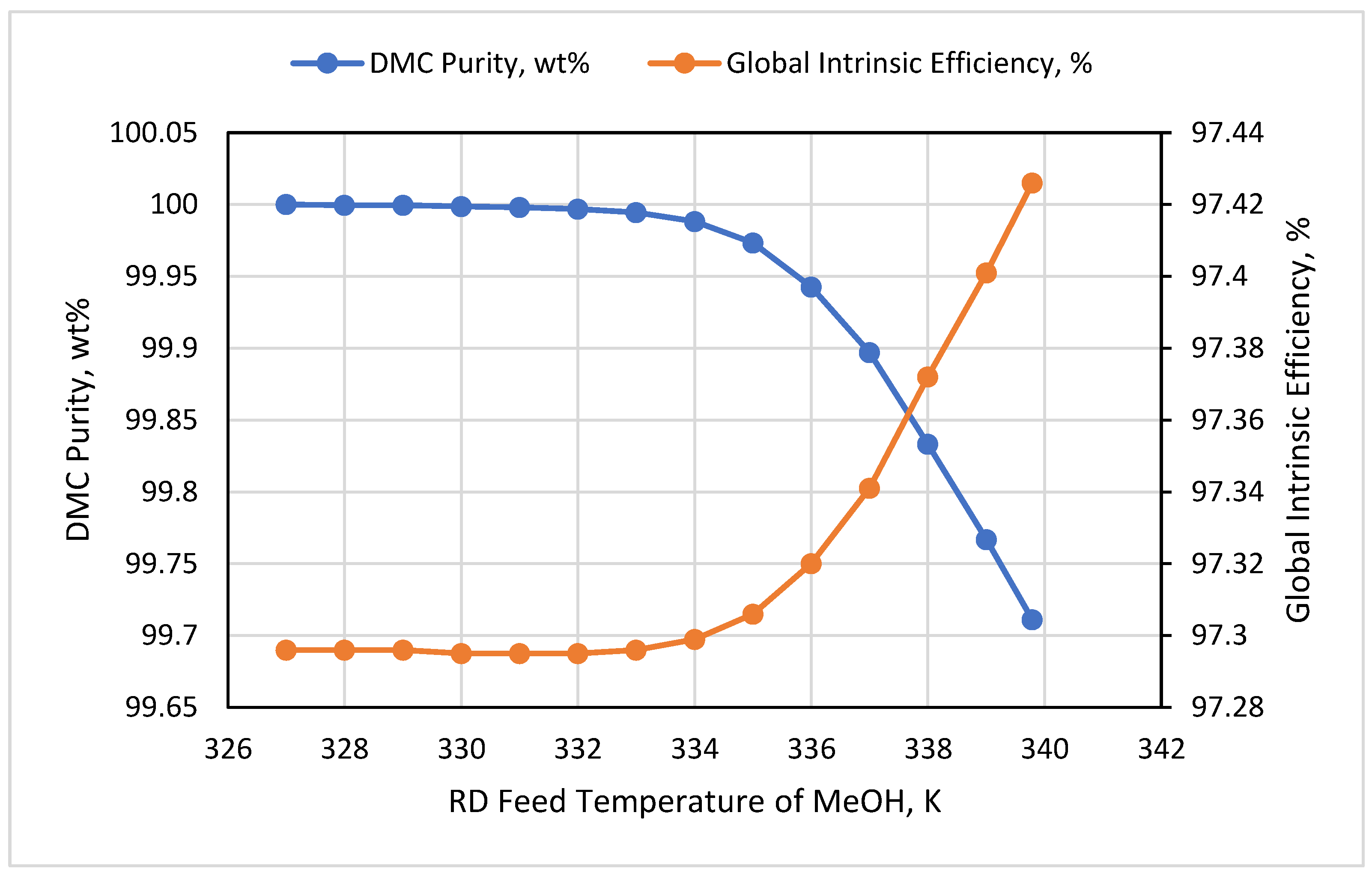
There are three streams feeding the RD column. Based on the optimized case presented in the literature, the first feed supplied pure MeOH at tray 45 of the RD column, the second feed was located at tray 5 supplying the mixture of MeOH and PC, while the third feed was the recycled distillate from the HP column at tray 16. Both the DMC purity and global intrinsic efficiency were plotted showing opposite trends when the feed temperature of the MeOH increased, as shown in Figure 12. Moreover, the two parameters behaved similarly when plotted versus the feed temperature of the MeOH + PC mixture as can be seen in Figure 13. Both figures show critical changes around the bubble point of MeOH and the MeOH + PC streams, respectively. However, the effect was observed to be very low, so exergy destruction could be managed by maintaining the feed temperatures around the bubble points.

4. Conclusions

The importance of Dimethyl Carbonate (DMC) comes from its chemical properties, which make it green and environmentally friendly. In this paper, the thermodynamic analysis was conducted for a well-optimized DMC process presented in the literature. The process was simulated using ProSimPlus software due to its unique capability to perform an exergy analysis, including all types of exergies. The important results obtained from this analysis can be listed as follows:
  • The positive variation in the RD reflux ratio played a crucial role on raising both the global irreversibilities and DMC purity. The results showed the critical change in destruction and purity after reaching the optimal reflux ratio used in the simulation (0.87), while there was no effect on the reboiler and condenser duties.
  • The effect of the HP reflux ratio was more feasible. The change in this ratio from 0.5 to 1.55 proportionally increased the irreversibilities and decreased both the exergy efficiency and the DMC purity. A major increase was observed in the HP reboiler and condenser duties. For the same reflux ratio range from 0.5 to 1.55, the reboiler duty was increased from 4.74 MW to 7.75 MW, respectively. The condenser duty was increased from 3.85 MW to 6.83 MW for the same range of the reflux ratio.
  • Keeping the HP feed temperature at its bubble condition or below this point was of high importance to hold the product at the desired purity. A tradeoff between the purity and irreversibilities could be performed by the process engineer to minimize the energy based on the economic targets.
  • The impact of the feed tray reflected that at tray 33, the exergy destruction was at maximum at 0.67 MW, and the global intrinsic efficiency was at a minimum at 97.43%, while the maximum DMC purity was determined to be 99.7 wt% at tray 33.
  • The exergy destruction had low change under the effect of the RD feed temperatures. Effective energy management can be achieved when holding these temperatures at their bubble points.

Funding

This research received no external funding.

Acknowledgments

The author extends his appreciation to the ProSimPlusTM group and the Aspen Technology Inc. group for their help and support during simulation process.

Conflicts of Interest

The author declares no conflict of interest.

References

  1. Pyo, S.-H.; Park, J.H.; Chang, T.-S.; Hatti-Kaul, R. Dimethyl carbonate as a green chemical. Curr. Opin. Green Sustain. Chem. 2017, 5, 61–66. [Google Scholar] [CrossRef]
  2. Tundo, P.; Selva, M. The Chemistry of Dimethyl Carbonate. Acc. Chem. Res. 2002, 35, 706–716. [Google Scholar] [CrossRef] [PubMed]
  3. Huang, Z.; Li, J.; Wang, L.; Jiang, H.; Qiu, T. Novel Procedure for the Synthesis of Dimethyl Carbonate by Reactive Distillation. Ind. Eng. Chem. Res. 2014, 53, 3321–3328. [Google Scholar] [CrossRef]
  4. Fukuoka, S.; Fukawa, I.; Tojo, M.; Oonishi, K.; Hachiya, H.; Aminaka, M.; Hasegawa, K.; Komiya, K. A Novel Non-Phosgene Process for Polycarbonate Production from CO2: Green and Sustainable Chemistry in Practice. Catal. Surv. Asia 2010, 14, 146–163. [Google Scholar] [CrossRef]
  5. Deng, W.; Shi, L.; Yao, J.; Zhang, Z. A review on transesterification of propylene carbonate and methanol for dimethyl carbonate synthesis. Carbon Resour. Convers. 2019, 2, 198–212. [Google Scholar] [CrossRef]
  6. Fang, Y.-J.; Xiao, W.-D. Experimental and modeling studies on a homogeneous reactive distillation system for dimethyl carbonate synthesis by transesterification. Sep. Purif. Technol. 2004, 34, 255–263. [Google Scholar] [CrossRef]
  7. Hsu, K.-Y.; Hsiao, Y.-C.; Chien, I.-L. Design and Control of Dimethyl Carbonate−Methanol Separation via Extractive Distillation in the Dimethyl Carbonate Reactive-Distillation Process. Ind. Eng. Chem. Res. 2009, 49, 735–749. [Google Scholar] [CrossRef]
  8. Huang, Z.; Lin, Y.; Wang, X.; Ye, C.; Li, L. Optimization and control of a reactive distillation process for the synthesis of dimethyl carbonate. Chin. J. Chem. Eng. 2017, 25, 1079–1090. [Google Scholar] [CrossRef]
  9. Kenney, W.F. Energy Conservation in the Process Industries; Academic Press: San Diego, CA, USA. [CrossRef]
  10. Dincer, I.; Zamfirescu, C. Advanced Power Generation Systems. Available online: http://elsevier.com/locate/permissions (accessed on 15 June 2022).
  11. Ghannadzadeh, A.; Thery-Hetreux, R.; Baudouin, O.; Baudet, P.; Floquet, P.; Joulia, X. General methodology for exergy balance in ProSimPlus® process simulator. Energy 2012, 44, 38–59. [Google Scholar] [CrossRef] [Green Version]
  12. Shi, Y.; Liu, H.; Wang, K.; Xiao, W.; Hu, Y. Measurements of isothermal vapor–liquid equilibrium of binary methanol/dimethyl carbonate system under pressure. Fluid Phase Equilibria 2005, 234, 1–10. [Google Scholar] [CrossRef]
  13. Kumar, P.; Srivastava, V.C.; Mishra, I.M. Dimethyl carbonate synthesis via transesterification of propylene carbonate with methanol by ceria-zinc catalysts: Role of catalyst support and reaction parameters. Korean J. Chem. Eng. 2015, 32, 1774–1783. [Google Scholar] [CrossRef] [Green Version]
  14. Wang, M.; Wei, T.; Sun, Y.; Wei, W.; Zhong, B. Synthesis of Dimethyl Carbonate from Propylene Carbonate and Methanol over Mesoporous Solid Base Catalyst; Marcel Dekker, Inc.: New York, NY, USA, 2003; pp. 659–666. [Google Scholar]
Figure 1. Optimized DMC Plant using Aspen Plus.
Processes 10 01219 g001
Figure 2. Optimized DMC Plant using ProSimPlus.
Processes 10 01219 g002
Figure 3. Effect of the RD Reflux Ratio on the Global Irreversibilities and DMC Purity.
Processes 10 01219 g003
Figure 4. Effect of the HP Reflux Ratio on the Global Irreversibilities and Intrinsic Efficiency.
Processes 10 01219 g004
Figure 5. Effect of the HP Reflux Ratio on the DMC Purity and Intrinsic Efficiency.
Processes 10 01219 g005
Figure 6. Effect of the HP Reflux Ratio on the Reboiler Duty and Condenser Duty.
Processes 10 01219 g006
Figure 7. Effect of the Feed Temperature on the Global Irreversibilities.
Processes 10 01219 g007
Figure 8. Effect of the HP Feed Temperature on the DMC Purity.
Processes 10 01219 g008
Figure 9. Effect of the HP Feed Temperature on the Reboiler Duty.
Processes 10 01219 g009
Figure 10. Effect of the Feed Tray Location on the Irreversibilities and Intrinsic Efficiency.
Processes 10 01219 g010
Figure 11. Feed Tray Location Versus Global Intrinsic Efficiency and DMC Purity.
Processes 10 01219 g011
Figure 12. Effect of the RD Feed Temperature of MeOH on the DMC Purity and Global Intrinsic Efficiency.
Processes 10 01219 g012
Figure 13. Effect of the RD Feed Temperature of the MeOH+PC Mixture on the DMC Purity and the Global Intrinsic Efficiency.
Processes 10 01219 g013
Table 1. Boiling Points of the Pure Components at Atmospheric Pressure.
Component IDTemperature/K
MeOH337.69
DMC363.37
PC514.97
PG460.76
Table 2. Comparisons of Experimental Azeotrope for MeOH/DMC at Different Pressures Against those of the Predicted Azeotrope for MeOH/DMC by ProSimPlusTM.
Pressure/kPaPredicted Value by ProSimPlusTMExperimental Value [12]
Tb/KMass FractionTb/KMass Fraction
101.3336.80(0.6996, 0.3004)337.35(0.7000, 0.3000)
405.2377.15(0.7864, 0.2136)377.15(0.7929, 0.2071)
607.8391.06(0.8170, 0.1830)391.15(0.8249, 0.1751)
1013.0410.23(0.8591, 0.1409)411.15(0.8761, 0.1239)
1519.5426.90(0.8951, 0.1049)428.15(0.9300, 0.0700)
Table 3. Comparisons of the Predicted Azeotrope for MeOH/DMC at Different Pressures by ProSimPlusTM and Aspen PlusTM in the Current Study.
Pressure/kPaPredicted Value by ProSimPlusTMPredicted Value by Aspen PlusTM
Tb/KMass FractionTb/KMass Fraction
101.3336.80(0.6996, 0.3004)336.80(0.7007, 0.2993)
405.2377.15(0.7864, 0.2136)377.18(0.7910, 0.2090)
607.8391.06(0.8170, 0.1830)391.10(0.8240, 0.1760)
1013.0410.23(0.8591, 0.1409)410.28(0.8713, 0.1287)
1519.5426.90(0.8951, 0.1049)426.94(0.9677, 0.0323)
Table 4. Plant Parameters for the Original, Optimal, and Current Designs.
Original Design [3]Optimized Design [8]Simulated Design
(Current Study)
RDHPRDHPRDHP
Total Stage352345424542
Pressure/MPa0.11.10.11.10.11.1
Feed StageNF1 = 10NF = 10NF1 = 5NF = 33NF1 = 5NF = 33
NF2 = 30 NF2 = 45 NF2 = 45
NFR = 16 NFR = 16 NFR = 16
Reflux Ratio (Rr)2.342.50.871.370.871.37
Condenser Duty/MW8.035.996.125.956.106.34
Reboiler Duty/MW8.276.305.576.985.577.26
Publisher’s Note: MDPI stays neutral with regard to jurisdictional claims in published maps and institutional affiliations.