Abstract
Electro-hydraulic servo pump control belongs to an electro-hydraulic coupling motion control system, which involves the mutual penetration and integration of mechanical, hydraulic, electrical, control, and other disciplines, as well as the time-varying, uncertain, multisource, and multifield problems of the internal and external excitation of the system, which makes the electro-hydraulic servo pump control system have the characteristics of a complex model, strong coupling, nonlinearity, and time-variation, resulting in the low accuracy and poor dynamic characteristics of the system. This paper takes a servo motor quantitative pump hydraulic cylinder load as the main dynamic line; divides the electro-hydraulic servo pump control system into a motor pump unit, a hydraulic transmission unit and a power output unit; analyzes its electromechanical coupling characteristics, pressure flow coupling characteristics, and mechanical–hydraulic coupling characteristics, respectively; studies the multiparameter characteristics of the system under the electromechanical–hydraulic coupling conditions; and summarizes the influence laws between the parameters. Finally, through a MATLAB/Simulink simulation, it provides a theoretical basis and guidance for high-performance control of the system.
1. Introduction
As one of the core technologies in the field of industrial equipment manufacturing, electro-hydraulic servo technology has very important applications in metallurgy, forging, military industry, shipping, rail transportation, and other industrial fields [1,2]. In the context of energy saving and emission reduction in green manufacturing, more and more experts and scholars are committed to the integration of electro-hydraulic servo technology and the green intelligent concept. The electro-hydraulic servo pump control system (EHSPCS) is one of the important research hotspots [3,4]. The EHSPCS is composed of a servo motor, a quantitative pump, a hydraulic cylinder, a functional valve set, and a controller. The servo motor and the quantitative pump are coaxially connected to form an electric servo pump unit (EPU, electro hydrostatic pump unit) [5,6]. The electro-hydraulic servo pump control system can effectively overcome the technical defects of electro-hydraulic servo valve control technology, such as poor antipollution ability, low equipment integration, serious energy waste, and high maintenance cost, and it also has the advantages of high efficiency, energy saving, a high power-to-weight ratio, and environmental friendliness [7,8]. Electro-hydraulic servo pumps belong to the electromechanical coupling motion control system, involving mechanical, hydraulic, electrical, control, and additional multidisciplinary mutual penetration and integration problems, made with a servo motor–quantitative pump–hydraulic cylinder–load as the main line of displacement servo and a hydraulic cylinder. The load transmission chain dynamics behavior is complex due to the complex system model, strong coupling, and nonlinear and time-varying characteristics [9,10]. Through the research on the electro-hydraulic coupling characteristics of the electro-hydraulic servo pump control system, the influence law between its internal parameters is analyzed, the key factors affecting the high-performance control of the system are determined [11,12], and the theoretical basis and guidance for the design of high-precision electro-hydraulic servo pump control system is provided. The electro-hydraulic coupling characteristics of the electro-hydraulic servo pump control system have been studied by relevant experts and scholars.
Europe and America first applied the electro-hydraulic servo pump control system to the aircraft actuation system EHA. Among them, NASA, Moog, Parker, Dryden Flight Research Center, Boeing, GE, Airbus in Europe, Lucas Institute, University of Sheffield in the UK, Linköping University in Sweden, Germany Hamburg-Harburg University of Technology, and others have been conducting research on aircraft electro-hydrostatic actuators [13]. As early as 1997, Moog Company in the United States conducted performance tests on the new EHA developed by it and installed it on the F-18 fighter for flight test [14]. By the 21st century, the main flight control surfaces of the American F35 fighter jets have all adopted EHA actuators [15]. In the field of industrial applications, American Rexroth (Rexroth) company proposed electro-hydraulic actuator products, which consist of servo synchronous motor, drive controller, plunger pump, hydraulic valve group, and control unit composition. The electro-hydraulic actuator has a maximum pressure of 35 MPa and a maximum load of 2500 kN. Wide application prospects in metal forming, die casting and blow molding machines, woodworking machinery, and valve drives [16].
For the electro-mechanical-hydraulic coupling characteristics, Aravindkumar D. Kotagond [17] from India studied the dynamic response characteristics of an electro-hydraulic servo pump control system under different loads. The experimental results show that the response speed of the system under a low-load condition is significantly higher than that under a high-load condition, revealing the coupling effect between the subsystems. Amin Maghareh [18] of Purdue University in the United States studied the coupling nonlinear relationship between a hydraulic cylinder and the electromechanical hydraulic system, established a controllable regular dynamics model of the system, and verified nonlinear specimens. Liu Dalong [19] from Nanning University in China, aiming at the energy-saving control problem of the load sensing system, established the dynamics model of the electro-hydraulic servo hydraulic system, constructed the objective function and added constraints, optimized the objective function with a dynamic programming algorithm, and analyzed the characteristics of the electro-hydraulic coupling energy flow of the system. Fu Yongling [20] from the Beijing University of Aeronautics and Astronautics in China elaborated the development history of the design method of the electro-hydraulic servo pump control system and summarized the electro-hydraulic parameter characteristics of the electro-hydraulic servo pump control system. Seong-ryeol Lee [21] from Korea Aeronautical University in Korea studied the asymmetric characteristics of the system flow and conducted an in-depth analysis on the nonlinear characteristics of the system flow. He proposed a dual electro-hydraulic servo pump control system, which acts as a redundant actuator in the system and thus improves the natural frequency of the system. Hai-bo Yuan [22] of Chonnam National University in South Korea established a nonlinear mathematical model of the system by considering nonlinear disturbances, such as oil compression and external load interference, and adopting the grey box system to identify model parameters. Gu Lichen [23] from Chang’an University in China studied the influence of oil properties on the volumetric efficiency and flow pulsation of hydraulic pumps and other components, and the results showed that oil compressibility and effective elastic modulus have complex nonlinear relations with the flow output of hydraulic pumps. Jiang Jihai [24] from the Harbin Institute of Technology in China analyzed the dead zone and nonlinear characteristics of the electro-hydraulic servo pump control system. By constructing the full-state feedback equation of the system, he proposed a discrete sliding mode control strategy based on the approach rate, and designed the controller for simulation and experimental study, which effectively improved the control performance of the system. Milind T.R. et al. [25] of the Indian Institute of Technology established the finite element model of an axial piston pump by combining multibody dynamics with the finite element method, studied the vibration nonlinearity of the hydraulic pump, and studied the main vibration mode and natural frequency characteristics of the unit assembly of the electro-hydraulic servo pump. Mccullough [26] of McMaster University studied the influence of oil temperature on the electro-hydraulic servo pump control system and determined the influence rule of oil temperature on the leakage coefficient, damping coefficient, and other important parameters of the system through detailed experimental methods. Haris Sheh Zad et al. [27] from Koç University in Turkey investigated and analyzed the control algorithm of the electro-hydraulic servo pump control system and summarized the parameter characteristics of the electro-hydraulic servo pump control system, such as nonlinear parameters, flow dead zone, sensor noise, and system time variation.
The above research has performed relevant research and analysis on the dynamic characteristics, static characteristics, nonlinear time-varying parameters, and other inherent characteristics of the electro-hydraulic servo pump control system. Compared to the existing methods in the literature, the main advantages of this paper are as follows:
- (1)
- Through the in-depth exploration of the coupling between the servo motor-hydraulic pump-hydraulic cylinder-load transmission chain, the mechanism of the electro-hydraulic coupling of the electro-hydraulic servo pump control system is analyzed in detail;
- (2)
- This paper takes the servo motor–quantitative pump–hydraulic cylinder–load as the main dynamic line and divides the electro-hydraulic servo pump control system into motor pump unit, hydraulic transmission unit, and power output unit. The electromechanical coupling characteristics, pressure flow coupling characteristics, and mechanical hydraulic coupling characteristics are analyzed, respectively, and the influence laws of various parameters are summarized, which provides a theoretical basis and guidance for the design of high-precision electro-hydraulic servo pump control system.
2. Principle of the Electro-Hydraulic Servo Pump Control System
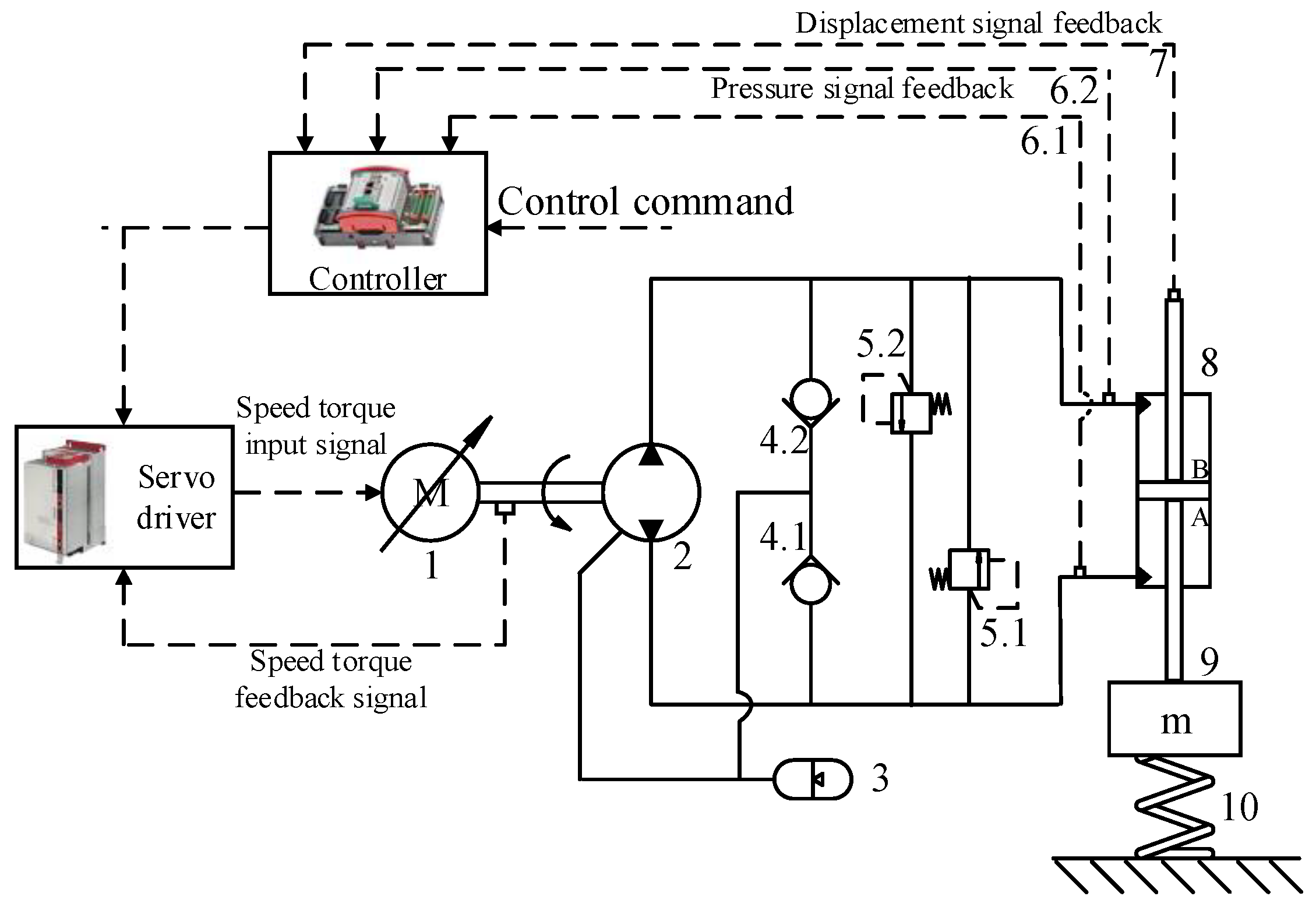
The configuration and working principle of the electro-hydraulic servo pump control system studied in this paper are shown in Figure 1, mainly including the servo motor, quantitative pump, hydraulic control valve group, accumulator, hydraulic cylinder, and control components.
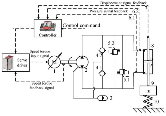
Figure 1.
Working principle diagram of the electro-hydraulic servo pump control system. 1: Servo motor, 2: positive displacement pump, 3: oil replenishment accumulator, 4.1: A-chamber check valve, 4.2: B-chamber check valve, 5.1: A-chamber check valve, 5.2: B-chamber check valve, 6.1: chamber A pressure signal, 6.2: chamber B pressure signal, 7: displacement signal, 8: symmetrical hydraulic cylinder, 9: fast load quality, and 10: load spring.
The electro-hydraulic servo pump control system adopts the volume control scheme of servo motor-hydraulic pump-hydraulic cylinder as the main line. The hydraulic pump selects a two-way high-pressure quantitative pump, and the suction and discharge ports of the quantitative pump are directly connected to the two load ports A and B of the hydraulic cylinder; the accumulator cooperates with the one-way valve to realize the oil supplement function of the system; the two chamber overflow valves of the hydraulic cylinders A and B realize the system pressure overload protection function. The controller collects information on the system pressure, displacement, and other states, compares and analyzes it with the control command, outputs the control information to the servo driver, and then drives the quantitative pump through the servo motor to realize the closed-loop servo control of the electro-hydraulic servo pump control system.
3. Analysis of Electro-Hydraulic Coupling Characteristics
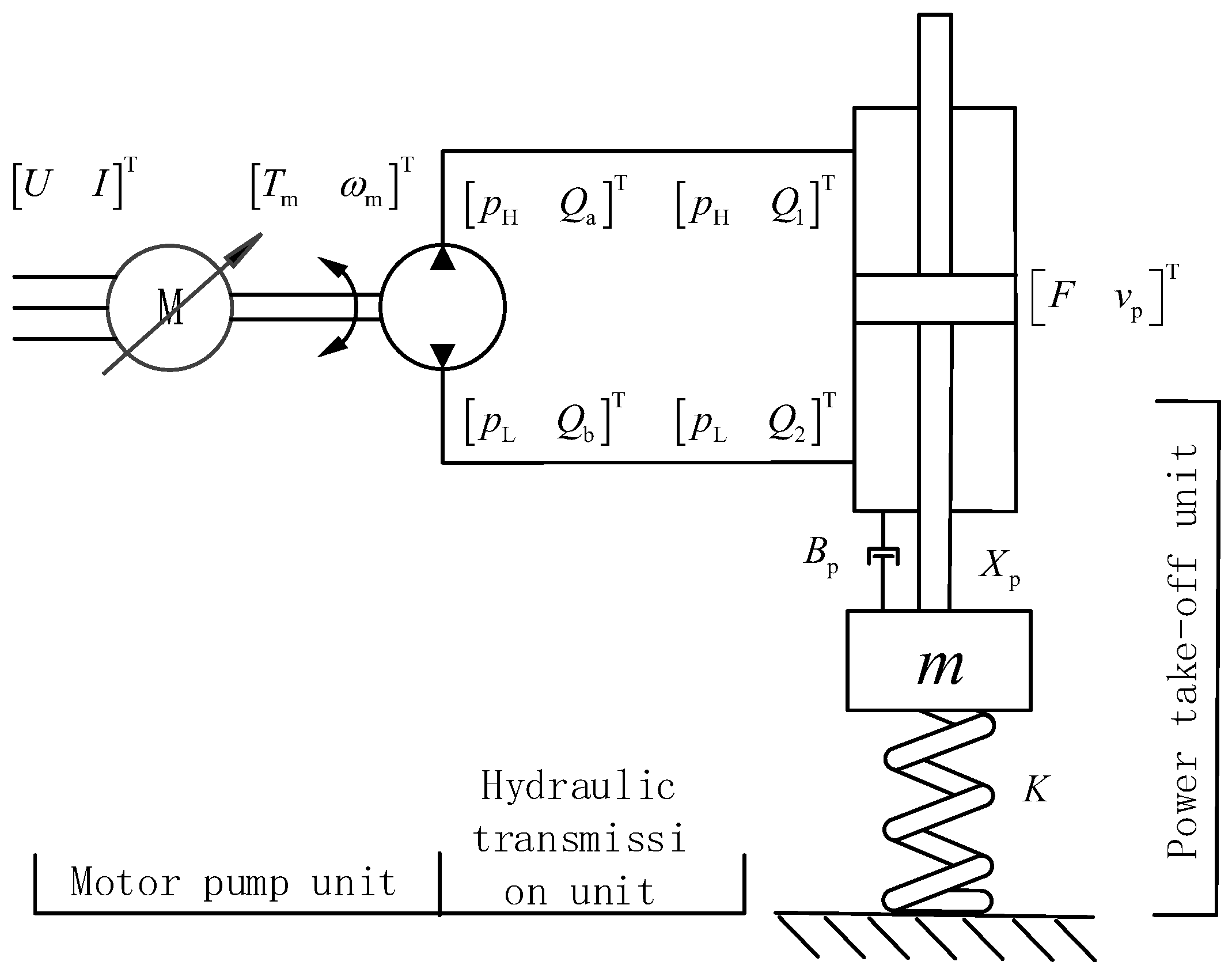
The electro-hydraulic servo pump control system uses the servo motor–quantitative pump–hydraulic cylinder–load as the main dynamic line. In order to facilitate the study of the electro-hydraulic coupling characteristics of the system, the system is divided into three parts: motor pump unit, hydraulic transmission unit, and power output unit, as shown in Figure 2.

Figure 2.
System composition diagram of electro-hydraulic coupling unit.
In the electro-hydraulic servo pump control system, the power output unit, hydraulic transmission unit, and motor pump unit have strong electromechanical–hydraulic coupling characteristics. The motor pump unit is characterized by electromechanical coupling, the hydraulic transmission unit is characterized by pressure flow coupling, and the power output unit is characterized by mechanical–hydraulic coupling.
3.1. Analysis of Mechanical–Hydraulic Coupling Characteristics
During the working process of the electro-hydraulic servo pump control system, when the two cavities of the hydraulic cylinder are completely closed, the hydraulic spring is formed due to the compressibility of the hydraulic oil, and the hydraulic cylinder is subject to the action of nonlinear hydraulic spring force. At the same time, under the joint action of external load force and load mass, there is the influence of load stiffness, which produces a mechanical–hydraulic coupling effect with the above hydraulic spring stiffness. Based on the hydraulic spring stiffness, this section will analyze the load characteristics of the hydraulic cylinder and explore the action law of the mechanical–hydraulic coupling stiffness between the hydraulic cylinder and the load.
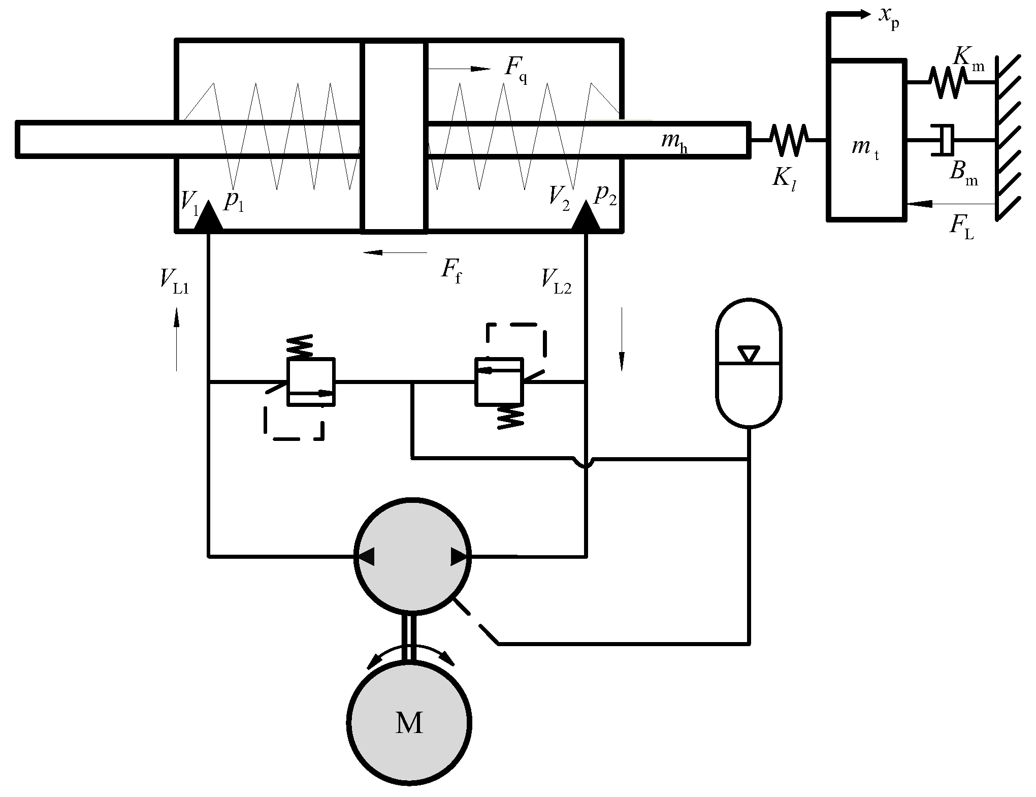
During the movement of the hydraulic cylinder, the mechanical–hydraulic coupling principle of hydraulic stiffness and load stiffness is shown in Figure 3.
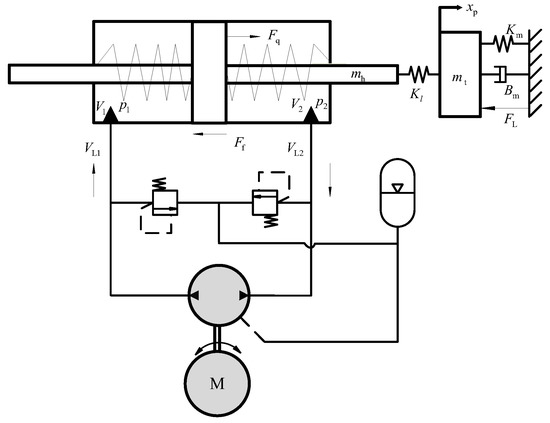
Figure 3.
Schematic diagram of system mechanical–hydraulic coupling.
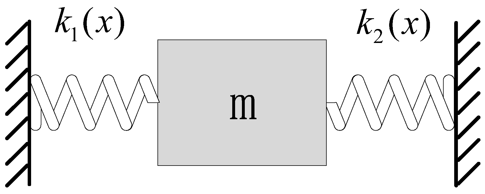
For the double-acting hydraulic cylinder model shown in Figure 3, the hydraulic spring model is shown in Figure 4.

Figure 4.
Hydraulic spring stiffness model.
When the piston of the hydraulic cylinder moves, the compression state of the hydraulic oil in the left and right chambers changes, and the stiffness of the hydraulic spring changes accordingly. The law of the hydraulic spring stiffness in the left chamber and the hydraulic spring stiffness in the right chamber of the hydraulic cylinder changing with the piston displacement can be expressed as:
where is the dead volume of the left chamber of hydraulic cylinder, is the dead volume of the right chamber of hydraulic cylinder, is the working area of the left and right chambers of the hydraulic cylinder, is the hydraulic cylinder left chamber volume and is the hydraulic cylinder right chamber volume.
Since the oil springs in the two chambers of the hydraulic cylinder are in parallel, the total hydraulic spring stiffness can be expressed as:
where is the bulk modulus of the elasticity of the oil; L is the total stroke of the hydraulic cylinder piston rod; α is the nonlinear coefficient of the left cavity, and its value range is 0 ≤ α ≤ 1; and γ is the nonlinear coefficient of the right cavity, and its value range is 0 ≤ γ ≤ 1. The values of α and γ represent that the hydraulic spring stiffness presents a nonlinear time-varying law with the movement of the piston. The values of α and γ are determined by the action areas of the left and right chambers of the hydraulic cylinder. In this article, the hydraulic cylinder is used as a symmetrical cylinder, so the values of α and γ are both 1.
The meaning of hydraulic spring stiffness Kh is the anti-compression capacity of the fluid in the hydraulic cylinder. The larger Kh is, the harder it is to compress the fluid in the hydraulic cylinder. The faster the pressure transmitted to the piston, the faster the response speed of the piston rod; otherwise, the slower it is.
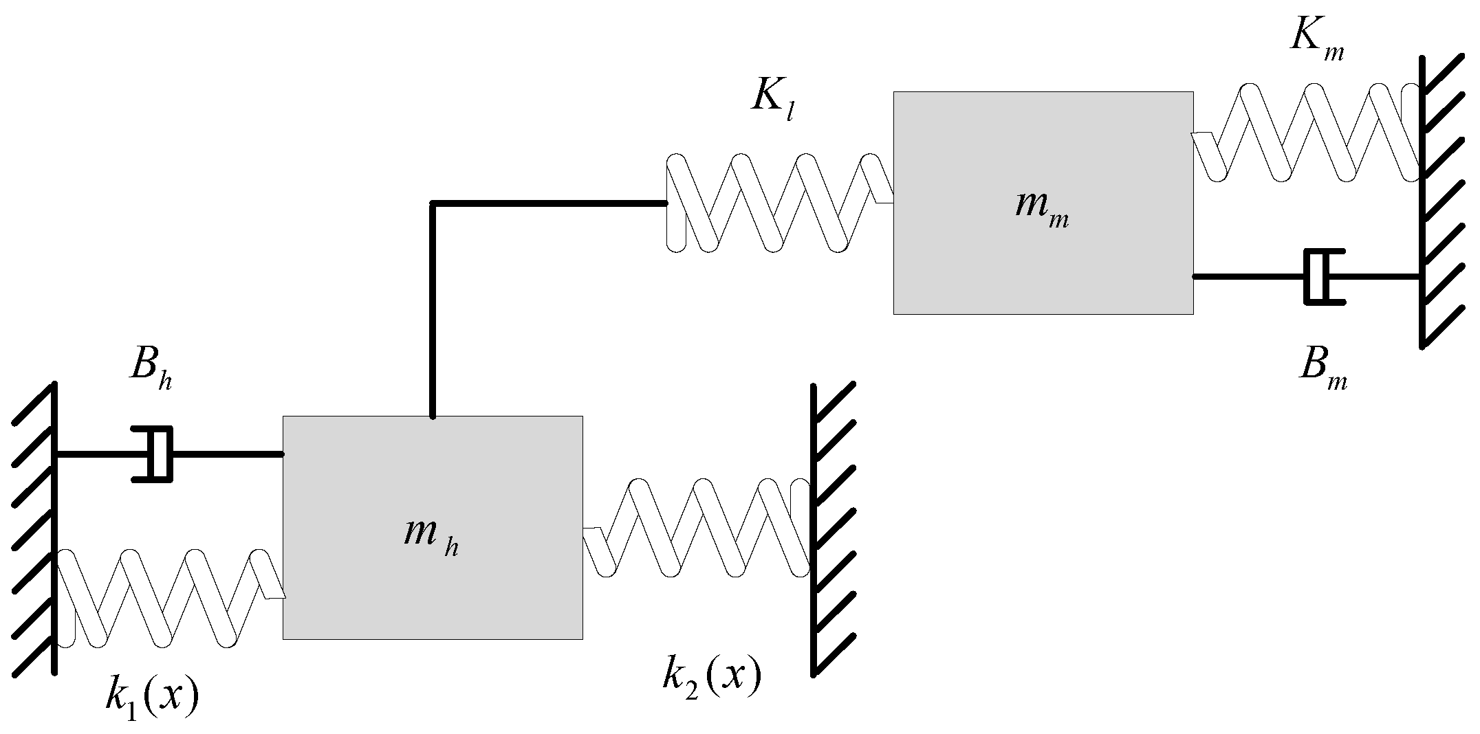
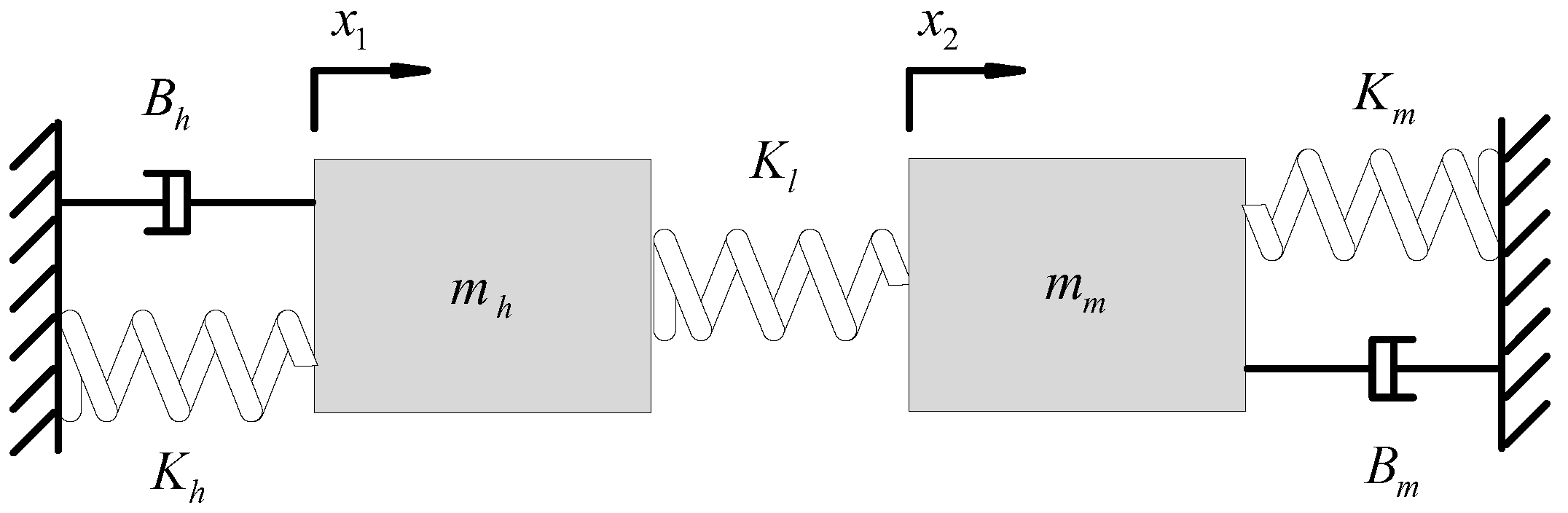
Furthermore, the stiffness coupling model formed by the load cavity hydraulic spring in Figure 3 and the load spring that changes with the stroke of the hydraulic cylinder can be simplified to the spring mass model shown in Figure 5.
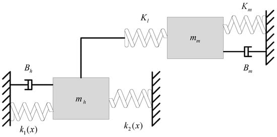
Figure 5.
Model diagram of the mechanical–hydraulic coupling spring mass block.
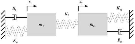
Figure 6.
Equivalent simplified diagram of mechanical–hydraulic coupling spring mass model.
In Figure 6, the spring stiffness , the piston rod and load connection stiffness , and the load stiffness are in a series, so the comprehensive mechanical–hydraulic coupling stiffness for of the system is:
According to Equation (3), the hydraulic spring stiffness, connection stiffness, and load stiffness are coupled to form a hydraulic cylinder mechanical–hydraulic coupling comprehensive stiffness. The comprehensive stiffness of the hydraulic cylinder hydraulic coupling is lower than that of the hydraulic spring, connection, and load. Generally, the connection stiffness is relatively large. Therefore, the comprehensive stiffness of the hydraulic cylinder mechanical–hydraulic coupling mainly depends on the hydraulic spring stiffness and load stiffness.
According to the two-free system in Figure 6, the differential equation of motion is established according to the dynamic theory. According to Newton’s second law, the following two equations can be obtained:
The above equation can be written in the following matrix form:
where
According to the above analysis, the undamped natural frequency of the machine fluid can be obtained. Without considering the damping effect, Equation (5) can be changed to:
Suppose the solution of Equation (6) is:
where , is the vibration amplitude, ω is the natural frequency, and φ is the initial phase.
Substituting Equation (7) into Equation (6), we can obtain:
Equation (8) is a generalized eigenvalue problem. For Equation (8) to have a solution, its coefficient determinant is zero, that is:
Substitute [K], [m] into Equation (9) to obtain:
Therefore,
where
Based on the above system analysis, it is known that the undamped natural frequency of the electro-hydraulic servo pump control system under the mechanical–hydraulic coupling is:
where
Under the mechanical–hydraulic coupling condition, the damping force of the electro-hydraulic servo pump control system is usually much less than the hydraulic driving force, which can be ignored. Therefore, the undamped natural frequency in Equation (12) can be used to characterize the mechanical–hydraulic coupling natural frequency characteristics of the hydraulic cylinder. Furthermore, based on the electromechanical–hydraulic coupling characteristics, the above mechanical–hydraulic coupling stiffness characteristics are simulated and analyzed, and the simulation results are shown in Figure 7 and Figure 8, respectively.
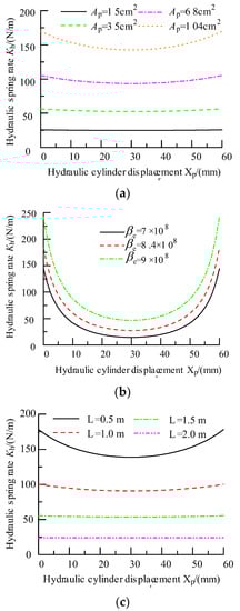
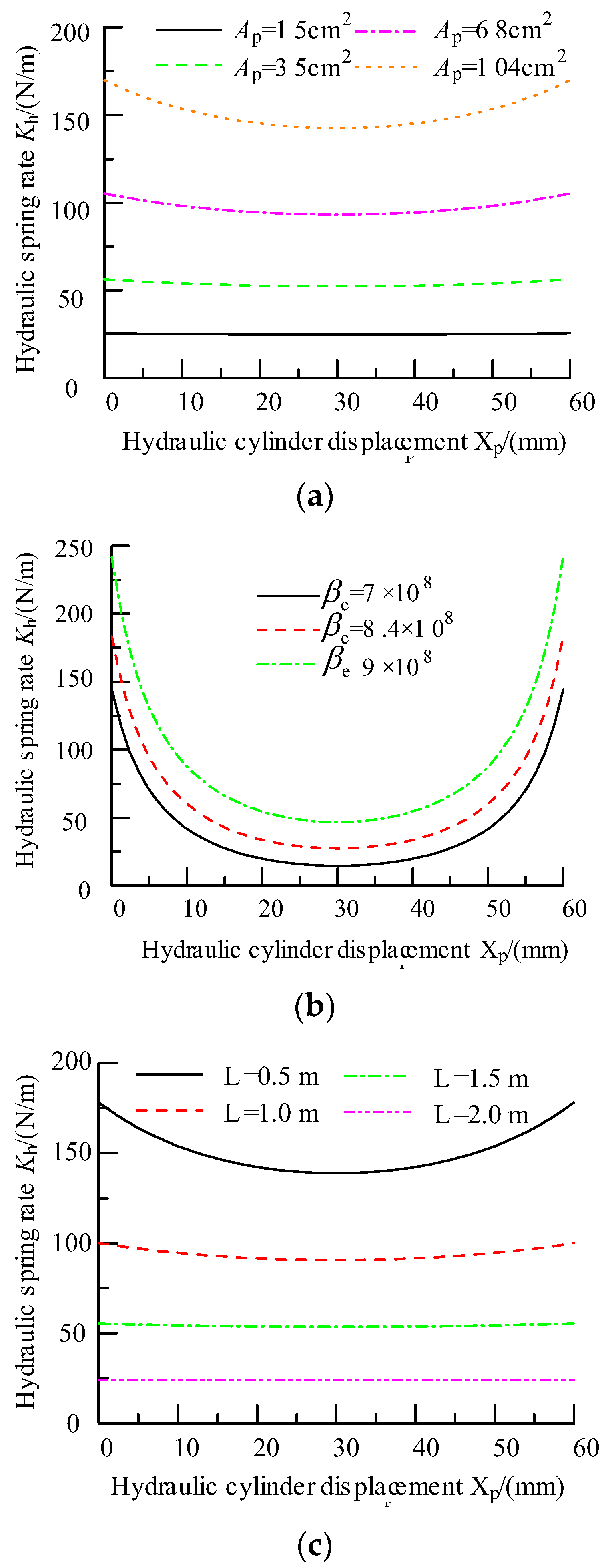
Figure 7.
Simulation diagram of hydraulic spring stiffness characteristics: (a) Simulation curve of hydraulic spring stiffness and hydraulic cylinder area; (b) simulation curve of hydraulic spring stiffness and bulk elastic modulus; and (c) simulation curve of hydraulic spring stiffness and pipeline length.
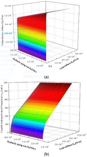
Figure 8.
Simulation diagram of system mechanical–hydraulic coupling characteristics: (a) Comprehensive stiffness simulation curve; and (b) simulation curve of coupled undamped natural frequency.
Figure 7 shows that the hydraulic spring stiffness increases with the increase in the action area of the hydraulic cylinder. At the same time, the nonlinear characteristics of the hydraulic spring stiffness become more prominent after the action area of the hydraulic cylinder increases. By increasing the action area of the hydraulic cylinder, the hydraulic spring stiffness can be increased to a certain extent, thereby improving the system response speed; the hydraulic spring stiffness increases with increasing oil volume elastic modulus and shows very strong time-varying and nonlinear characteristics. For the electro-hydraulic servo pump control system, the closed system needs to be filled with liquid and vented to ensure the stability of the oil volume elastic modulus and the avoidance of the hydraulic spring stiffness jump; in addition, the length of the system connecting pipeline will further produce a nonlinear action law on the hydraulic spring stiffness. The increase in the pipeline length will reduce the hydraulic spring stiffness and inhibit the rapid response ability of the system. Therefore, the electro-hydraulic servo pump control system usually adopts the integrated installation form to reduce the connecting pipeline between the quantitative pump and the hydraulic cylinder and then improve the stiffness of the hydraulic spring.
Figure 8 shows that when the load stiffness is very large, the comprehensive stiffness of the hydraulic cylinder mechanical–hydraulic coupling is close to the stiffness of the hydraulic spring. At this time, the undamped natural frequency of the system determines the response speed of the system; when the load stiffness is equal to the hydraulic spring stiffness, the response speed of the system is determined by both, and the load stiffness cannot be ignored. Because the load mass is usually inconvenient to adjust, in order to improve the response speed of the system, it is necessary to consider both the hydraulic spring stiffness and the load stiffness.
3.2. Analysis of Pressure Flow Coupling Characteristics
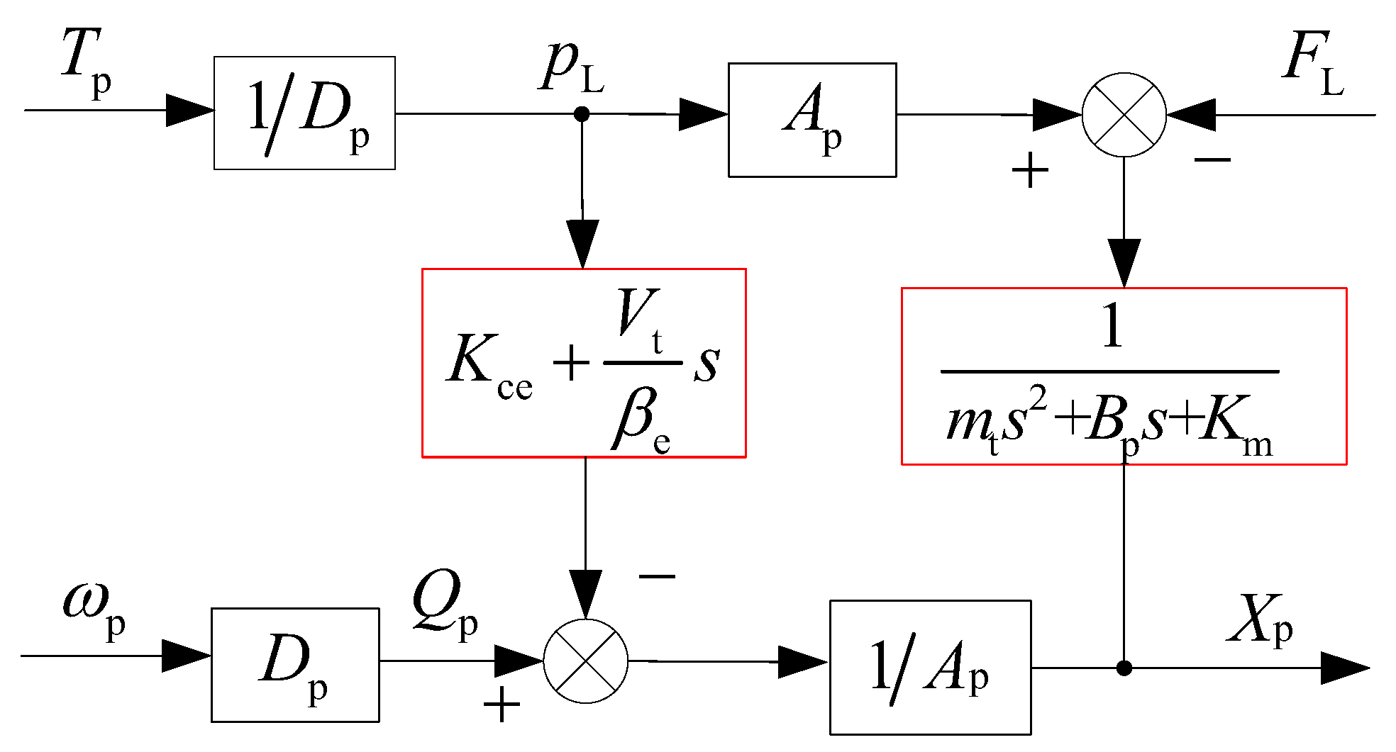
Because the electro-hydraulic servo pump control system adopts the volume servo direct drive mechanism, which is different from the traditional generator system, the proportional servo valve cannot be used to realize the decoupling control of the system pressure and flow. In the hydraulic transmission unit composed of the quantitative pump and the hydraulic cylinder, the two most basic control variables, flow and pressure, are seriously coupled in the system. In the load chamber, when one variable is adjusted, the other variable will change accordingly. The control block diagram of the quantitative pump hydraulic cylinder transmission unit was arranged as shown in Figure 9.
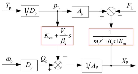
Figure 9.
System pressure flow coupling block diagram.
According to the analysis in Figure 9, when the load pressure changes, the load flow output will be affected by the total leakage coefficient of the system and the elastic compression of the oil volume, and is called the coupling interference factor between the system pressure and the flow; the load flow produces displacement deformation through the action of the hydraulic cylinder area, and then indirectly affects the change in load pressure through inertial load force, viscous load force, and elastic load force. The is called the coupling interference factor between system flow and pressure. Because the electro-hydraulic servo pump control system adopts the servo direct drive structure, the quantitative pump directly drives the hydraulic cylinder and lacks the decoupling control link of the intermediate control valve group; the pressure and flow of the hydraulic transmission unit have strong coupling characteristics. The pressure flow coupling characteristics of the system are simulated and analyzed, and the simulation curve is shown in Figure 10.
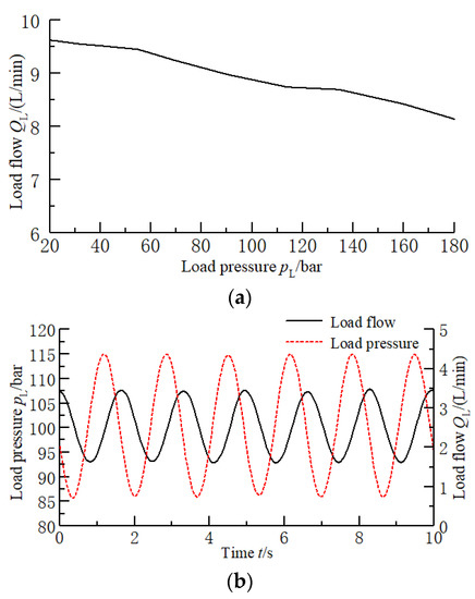
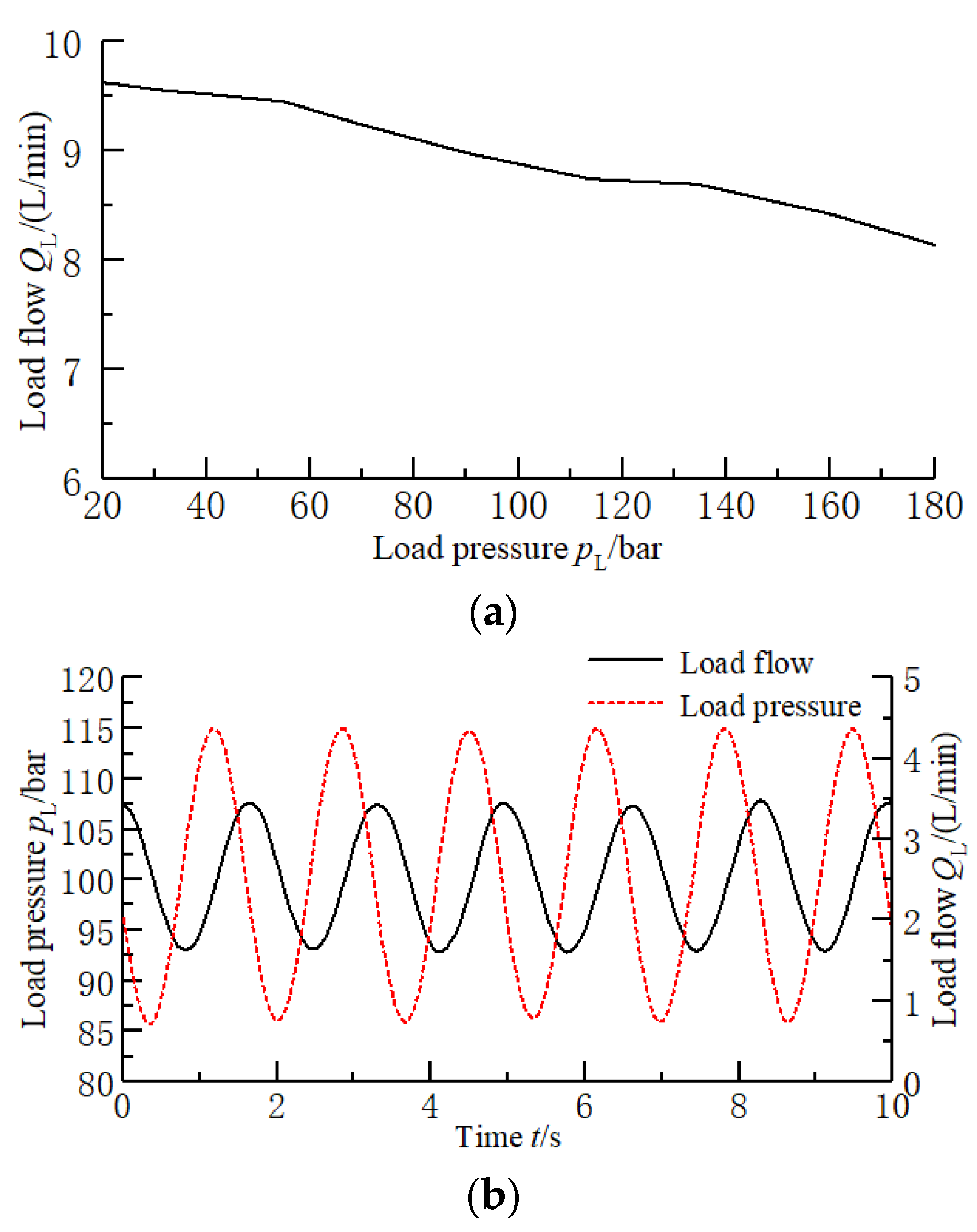
Figure 10.
Simulation diagram of system pressure and flow coupling characteristics: (a) Simulation diagram of influence of system pressure on flow; and (b) simulation diagram of the effect of system flow on pressure disturbance.
The simulation results in Figure 10 show that the increase in load pressure will aggravate the system leakage and oil compression characteristics and, to a certain extent, lead to droop attenuation characteristics in the load flow, affecting the output of the load flow; when the servo motor adopts a variable speed input and the system acts on the alternating load flow, the load pressure is adjusted accordingly. The frequency of the two actions is similar, but there is a certain lag in the phase. Therefore, in order to improve the control accuracy of the electro-hydraulic servo pump control system, it is recommended to use it in the condition of low frequency. To summarize, under the volume servo direct drive structure, the hydraulic transmission unit composed of quantitative pump and hydraulic cylinder has strong pressure flow coupling characteristics.
3.3. Analysis of Electromechanical Coupling Characteristics
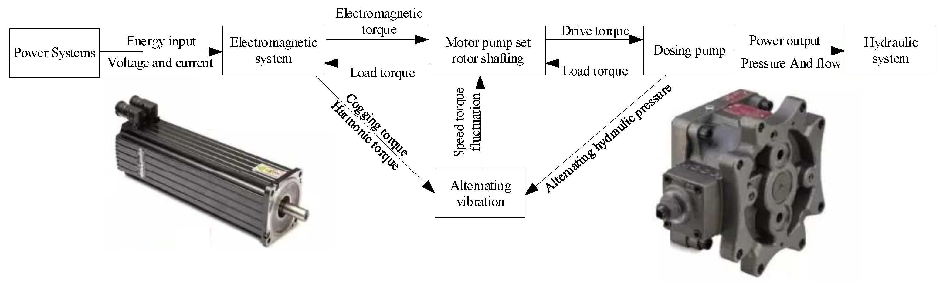
During the working process of the motor pump unit, the electric power input of the servo motor generates electromagnetic rotation and drives the output pressure and flow of the quantitative pump through the rotor shaft system of the motor pump unit. This process involves the mutual coupling between the electric power system, the electromagnetic system, the mechanical system, and the hydraulic system.
On the one hand, from the perspective of electric drive, under the action of a three-phase voltage and current, the stator and rotor cooperate to form a coupling electromagnetic field, and the rotor rotation generates electromagnetic torque to drive the rotor shafting of the motor pump set to rotate. In addition, considering the dynamic fluctuation of voltage and current, magnetic leakage, and magnetic saturation effects of stator and rotor, the servo motor will form a certain cogging torque and harmonic torque, which will generate alternating vibration excitation to the rotor shafting of the motor pump unit, and finally, form the dynamic coupling of the electromagnetic system and mechanical system.
On the other hand, from the perspective of the hydraulic system, the output pressure and flow of the quantitative pump under the driving torque, as well as the load torque, react on the rotor shafting of the motor pump unit. In addition, considering the high-speed rotation of the quantitative pump, the internal plunger interacts with the cylinder block to form alternating hydraulic pressure, which generates alternating vibration excitation to the rotor shafting of the motor pump set, and finally, forms the dynamic coupling between the hydraulic system and the mechanical system.
The above analysis shows that the coupling relationship between the servo motor and the quantitative pump is established by mechanically connecting the rotor shafting, as shown in Figure 11.
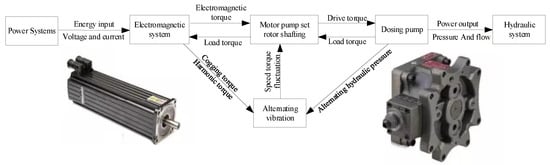
Figure 11.
Electro-hydraulic coupling relationship diagram of the motor pump unit.
As shown in Figure 11, the servo motor and the quantitative pump form a coupling relationship, which is mainly reflected in the rotation and alternating vibration of the rotor shafting of the motor pump unit. Considering that the effects of cogging torque, harmonic torque, and alternating hydraulic pressure are small, the study of the high-performance control of the rotor shafting can be omitted. This section will focus on the electromechanical coupling characteristics of the motor pump unit rotor shafting and analyze the rotating motion mechanism of the rotor shafting under the external excitation force.
3.3.1. Dynamic Coupling Model of Rotor Shafting
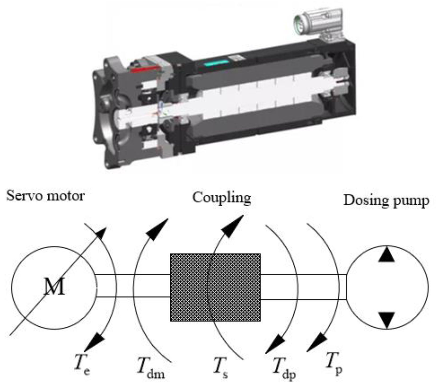
Considering that there are installation errors between the servo motor and the fixed displacement pump during the installation process, which may easily lead to radial and axial misalignment and affect the stability of the system operation, the two are usually connected and compensated by elastic coupling, such as quincunx coupling. The basic mechanical structure of the rotor shafting of the motor pump unit is shown in Figure 12.
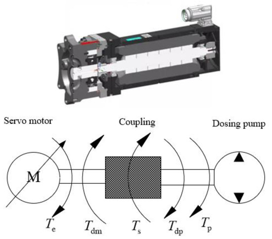
Figure 12.
Structure diagram of the EPU rotor shaft system.
As shown in Figure 12, according to the dynamic torque balance relationship of the rotor shaft system, its differential equation can be expressed as:
According to Equation (13), the state-space expression of the rotor shafting model can be obtained as:
where is the rotor shafting torque, is the motor end damping torque, is the constant pump end damping torque, is the viscous damping coefficient at the motor end, is the viscous damping coefficient of the constant displacement pump end, and is the torsional stiffness coefficient of the rotor shafting.
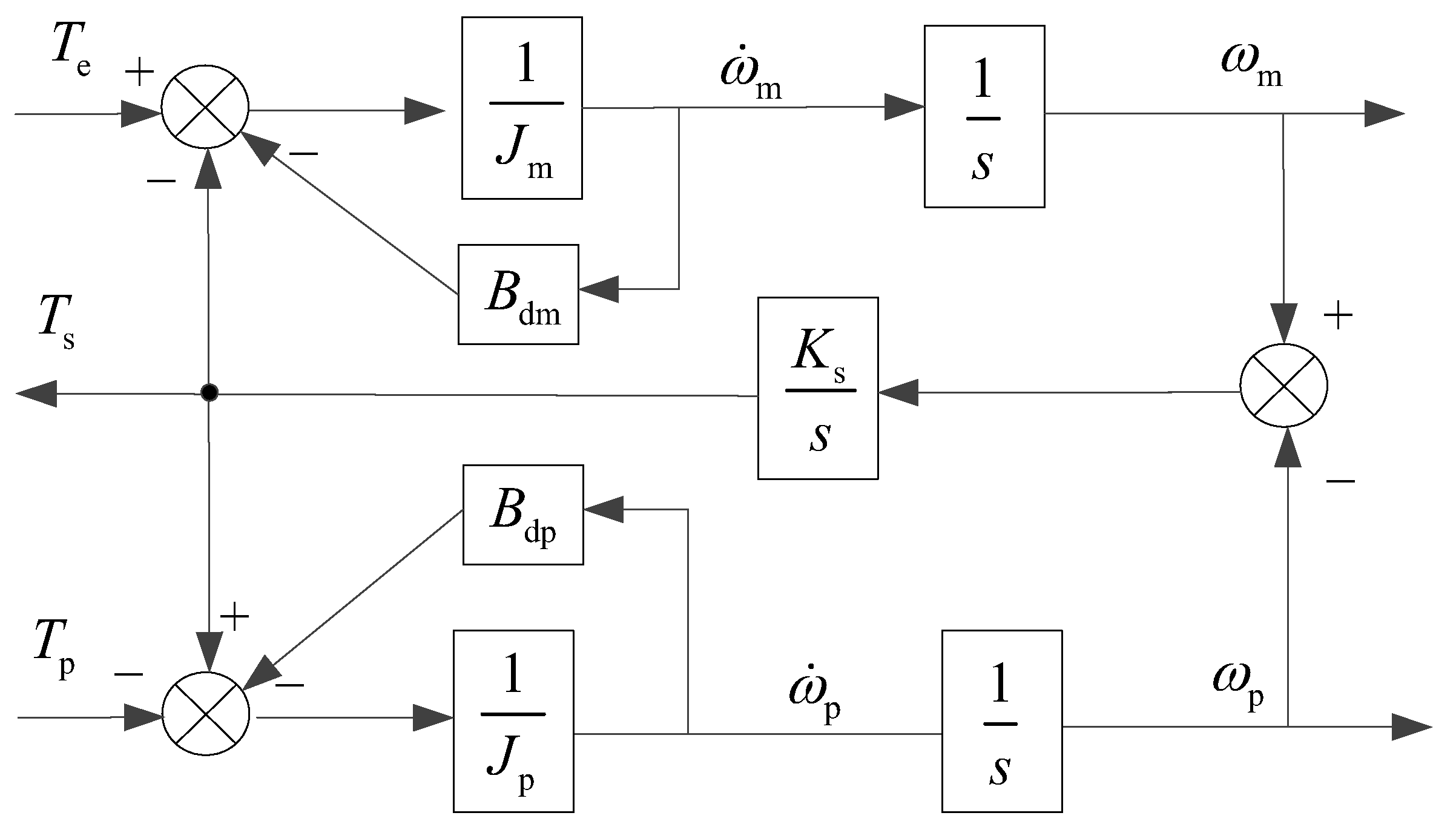
Based on the above mathematical model, the transfer function model block diagram of rotor shaft system can be established, as shown in Figure 13.
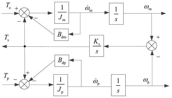
Figure 13.
Block diagram of rotor shaft system transfer function.
Furthermore, the transfer function expression of motor speed and electromagnetic torque under the rotor shaft system can be obtained as follows:
Generally, the viscous damping is small and negligible, so Equation (7) can be simplified as:
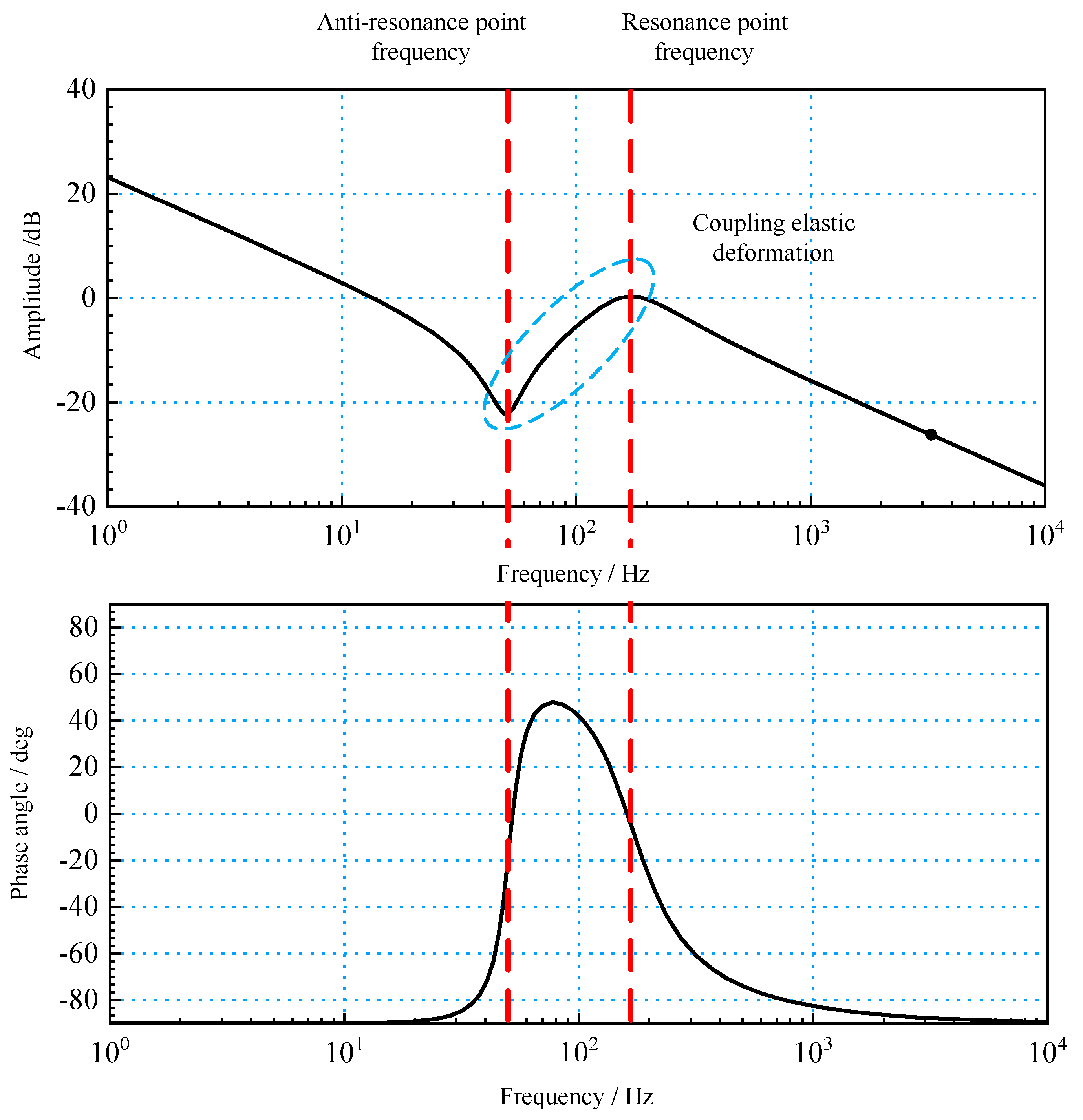
Equation (16) shows that the rotor shaft system motor speed and electromagnetic torque transfer function reflect certain resonance characteristics, and there are two resonance points with sudden phase change. The corresponding frequencies are called the resonance frequency ωfr and anti-resonance frequency ωar; the specific mathematical expressions are:
Equation (17) shows that the resonance frequency and anti-resonance frequency mainly depend on the stiffness coefficient of the rotor shafting and the moment of inertia of the servo motor and quantitative pump. When the moment of inertia of the constant displacement pump is much larger than that of the servo motor, the resonance frequency is approximately equal to the anti-resonance frequency, and the resonance cancellation can be realized; when the moment of inertia is determined, increasing the stiffness coefficient of the rotor shaft system will help to improve the resonant frequency and anti-resonant frequency.
Based on the above analysis, the Bode diagram corresponding to the transfer function of motor speed and electromagnetic torque is shown in Figure 14.
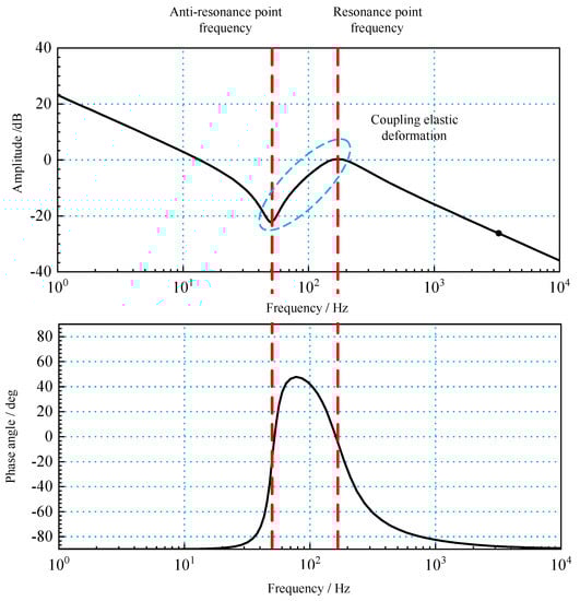
Figure 14.
Bode diagram of rotor shaft system dynamic characteristics.
The above analysis shows that the electromechanical coupling characteristics of the rotor shafting of the motor pump unit are mainly reflected in the resonant characteristics of the shafting itself and the setting of control parameters in the control correction process, while the shafting resonant characteristics are mainly determined by the shafting stiffness and moment of inertia according to Equation (9). Therefore, this section will analyze the electromechanical coupling characteristics of the rotor shafting from the three aspects of moment of inertia, shafting stiffness, and control parameters.
3.3.2. Analysis of the Moment of Inertia Characteristics of Rotor Shafting
After the power selection of the servo motor, its moment of inertia is basically determined. Therefore, the moment of inertia characteristics of the rotor shafting can be studied from the perspective of the inertia ratio of the load metering pump and servo motor.
In the rotor shafting, if the ratio of the moment of inertia at the quantitative pump end to the moment of inertia at the servo motor end is KJ, then:
The above inertia ratio in the rotor shafting of motor pump unit has an important influence on the dynamic characteristics of the system, as shown in Figure 15.
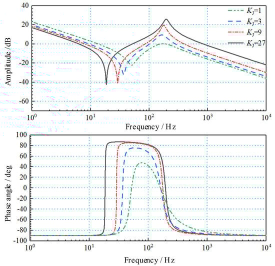
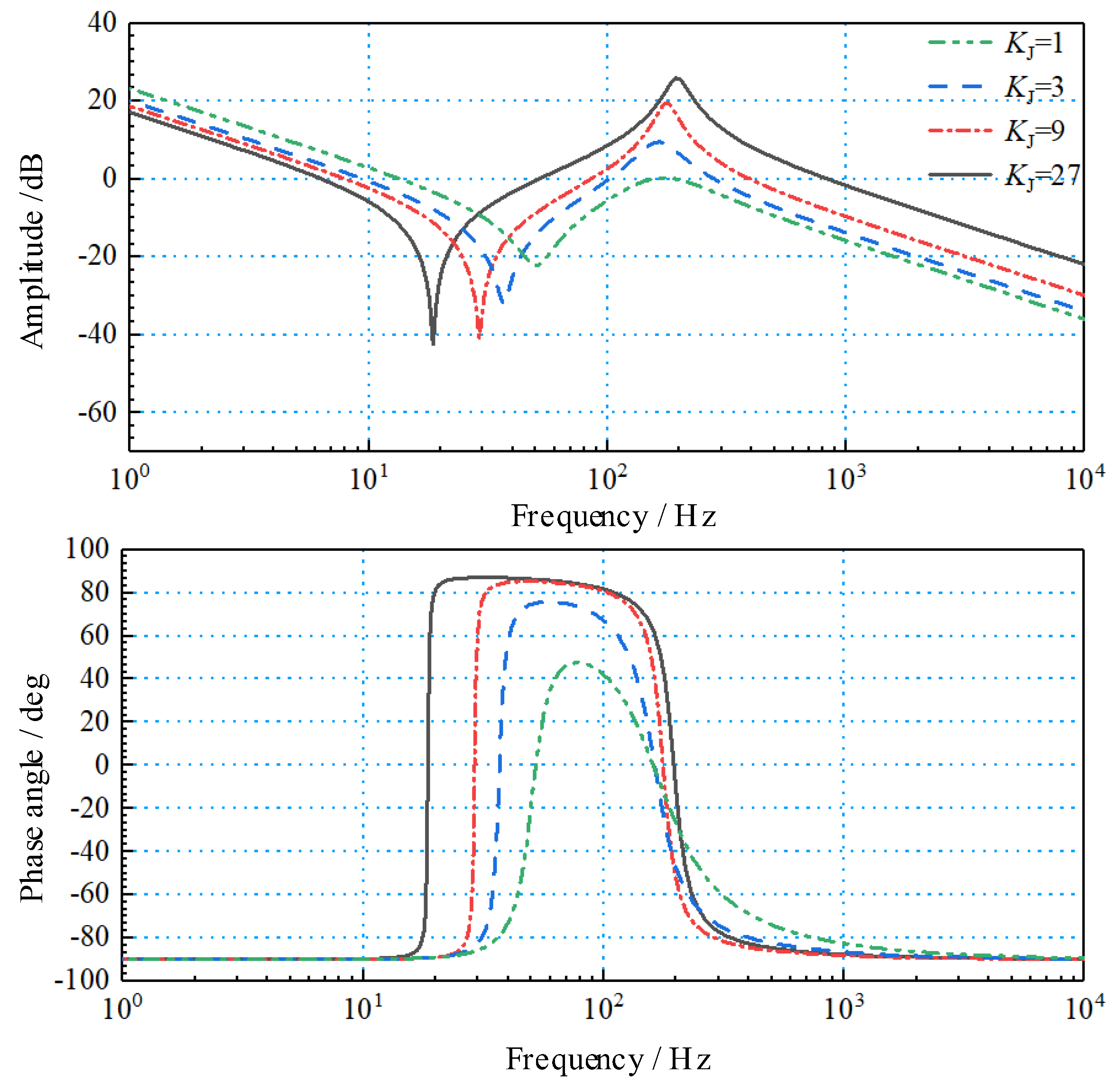
Figure 15.
Open-loop Bode diagram under different moment of inertia ratios.
Figure 15 shows that with the increase in the inertia at the dosing pump end, the ratio of the moment of inertia KJ becomes larger, which reduces the open-loop cut-off frequency of the system and the response characteristics of the system; however, the larger ratio of the moment of inertia will increase the amplitudes of the resonance point and anti-resonance point and further increase the difference between resonance frequency and anti-resonance frequency, which will aggravate the system vibration. When KJ = 1, the rotor shafting has a good open-loop cut-off frequency and the lowest resonance peak. Therefore, the combination of the moment of inertia Jm of the servo motor and the moment of inertia Jp of the quantitative pump load has an important impact on the dynamic response, stability, and control accuracy of the rotor shafting and even the whole system, which can make the moment of inertia Jm of the servo motor close to the moment of inertia JL of the quantitative pump load; this improves the dynamic characteristics of the system, reduces the harmonic amplitude of the resonance point, and increases the stability of the servo system, thereby realizing the fast and stable conversion of the electric power of the servo motor.
3.3.3. Analysis of Stiffness Characteristics of Rotor Shafting
The stiffness of the rotor shafting affects the electromechanical coupling characteristics of the motor pump unit through the action of resonant frequency and anti-resonant frequency. When the stiffness of the rotor shaft system is large enough and its mechanical deformation can be ignored (that is, KS tends to infinity), the rotor shaft system forms a rigid transmission system in a strict sense, and Equation (16) can be simplified as:
In the actual system, in order to overcome the radial and axial misalignment between the servo motor and the fixed displacement pump, a certain elastic coupling is usually used, which makes the rotor shaft system have certain mechanical deformation that cannot be ignored and forms a flexible deformation. A Bode diagram of the rotor shafting under different stiffnesses is shown in Figure 16.
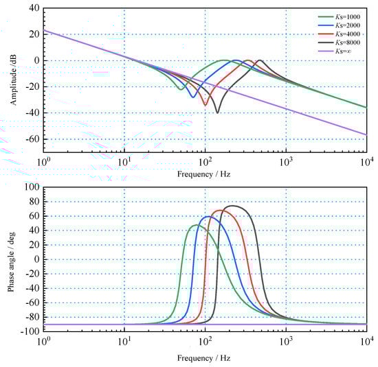
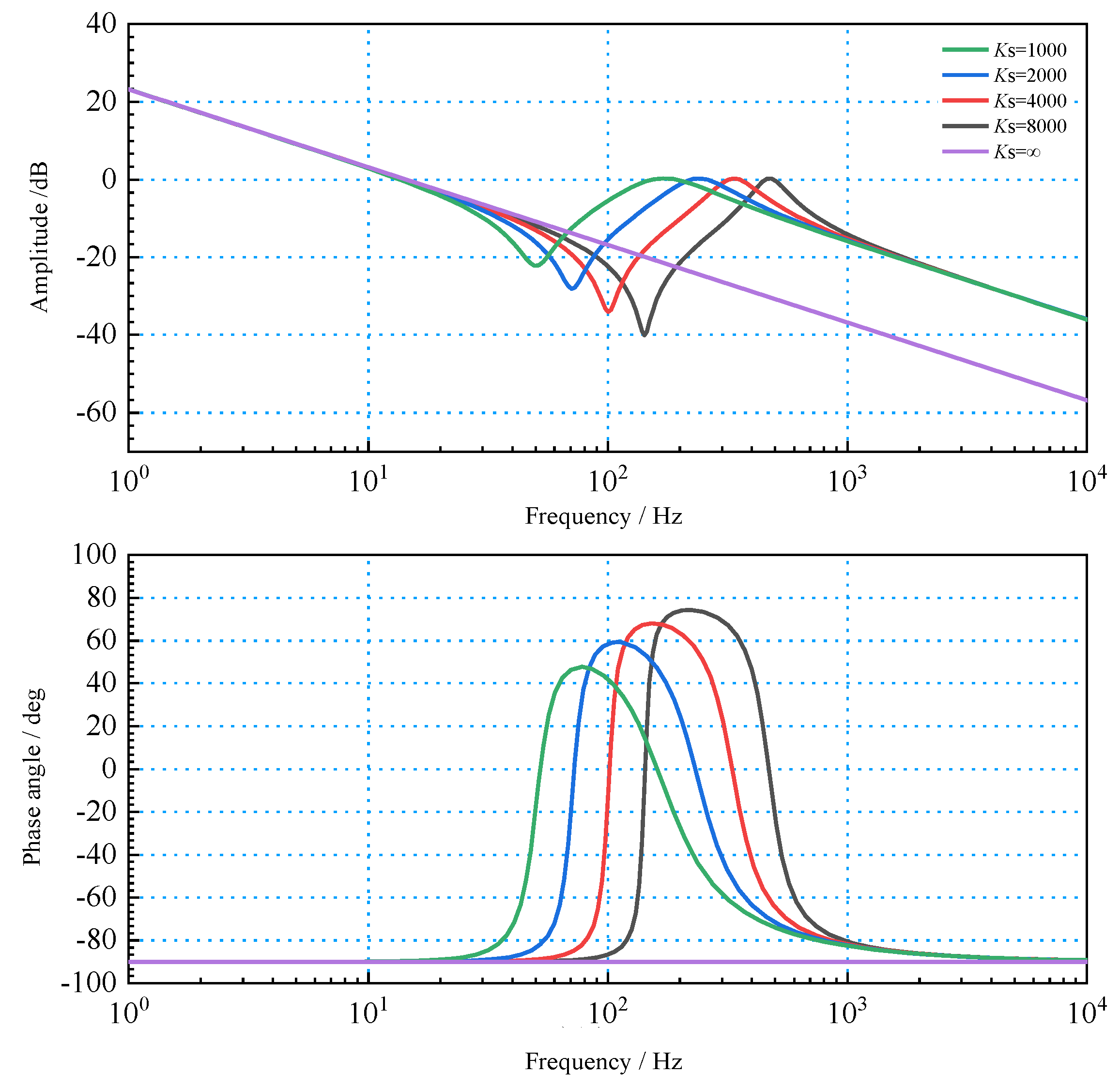
Figure 16.
Bode diagram of rotor shafting stiffness characteristics.
Figure 16 shows that the stronger the stiffness of the rotor shafting, the higher the resonance frequency and anti-resonance frequency. Low-frequency rotor stiffness characteristics are not outstanding. With the increase in frequency, the rotor shafting appears to produce a mechanical resonance in the middle-frequency band, and the amplitude of vibration is positively correlated with the shafting stiffness. After entering the high-frequency band, the amplitude decreases rapidly.
3.3.4. Influence Analysis of Control Parameters
In addition to inherent properties, such as inertia and stiffness, the electromechanical coupling characteristics of the rotor shafting are also affected by the control parameters during the control correction process. Using the open-loop gain as a typical example, the influence of control parameters on the rotational motion of the rotor shafting was studied, and the Bode diagram was obtained as shown in Figure 17.
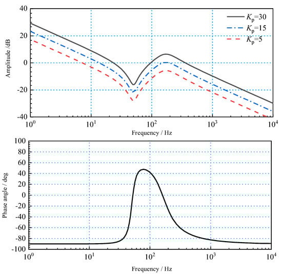
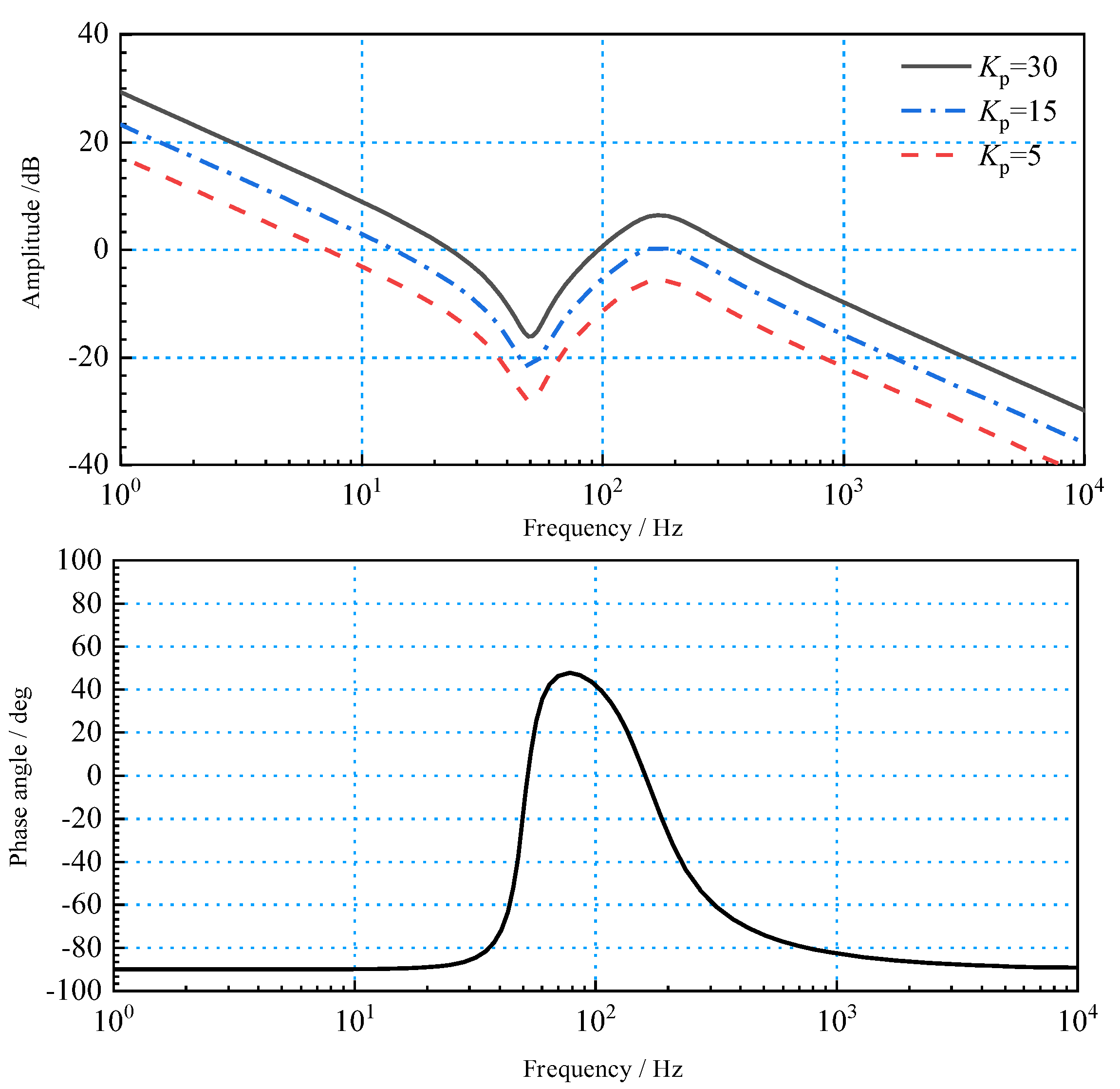
Figure 17.
Open-loop Bode diagram under different open-loop gains.
Figure 17 shows that, with the increase in the open-loop gain Kp, the open-loop cut-off frequency of the rotor shafting gradually increases, which helps to improve the rapidity of the rotor shafting; however, the open-loop gain Kp increases the resonant frequency amplitude of the rotor shaft system at the same time. The high-frequency amplitude can easily produce mechanical resonance, which affects the stability of the system. Therefore, in the process of selecting control parameters, both the speed of the rotor shafting adjustment and the stability of the resonance should be considered.
4. Discussion
In the process of studying the electro-hydraulic coupling characteristics of the electro-hydraulic servo pump control system, the influence characteristics of different coupling parameters in the system on the rapidity, stability and accuracy of the electro-hydraulic servo pump control system are analyzed by simulation in this way:
- (1)
- Through the analysis of the rotary inertia characteristics of the rotor shaft system, it can be concluded that the rotary inertia of the servo motor can be adjusted to be close to that of the quantitative pump load, so as to improve the dynamic characteristics of the system, reduce the harmonic amplitude of the resonance point and increase the stability of the servo system;
- (2)
- Through the analysis of the stiffness characteristics of the rotor shaft system, it can be concluded that when the electro-hydraulic servo pump control system is applied in low frequency occasions, the control precision of the system is higher;
- (3)
- Through the analysis of the influence of control parameters on the rotating motion of rotor shafting can be obtained. Increasing the open-loop gain will not only improve the speed of rotor shafting adjustment, but also improve the amplitude of resonant frequency and reduce the stability. Therefore, both rapidity and stability need to be considered.
5. Conclusions
Taking the electro-hydraulic servo pump control system as the research object, the multi-parameter characteristics of the system under the electro-hydraulic coupling condition were studied. Following conclusions are drawn:
- (1)
- Analysis of machine-hydraulic coupling characteristics: The research and analysis on the establishment of hydraulic spring stiffness shows that increasing the hydraulic cylinder action area, reducing the air content in the oil to increase the oil volume elastic modulus and reducing the pipeline connection length increase the hydraulic spring stiffness. Thereby improving the rapidity of the system.
- (2)
- Pressure flow coupling characteristics: By establishing a pressure flow coupling block diagram and simulating its parameters, the results show that the load pressure is reduced and the action frequency is reduced, that is, the electro-hydraulic servo pump control system is applied in the occasions where the action frequency is low, the higher the control precision of the system.
- (3)
- Electromechanical coupling characteristics: According to the analysis of the article, the electromechanical coupling characteristics are mainly reflected in the setting of the moment of inertia, shaft stiffness and control parameters.
The following work will apply the results obtained by the simulation analysis to the design of the actual electro-hydraulic servo pump control system and quantitatively analyze the electro-hydraulic coupling characteristics of the electro-hydraulic servo pump control system by means of experiments.
Author Contributions
Conceptualization, W.J. and C.Z.; methodology, G.C.; experiment and analysis, G.Y. and P.J.; software, C.Z.; investigation, W.J.; writing—original draft preparation, C.Z. and P.J.; writing—review and editing, G.C. and T.Z.; project administration, R.M.; funding acquisition, C.A. All authors have read and agreed to the published version of the manuscript.
Funding
This research was supported by the Key R&D Projects in Hebei Province (no. 20314402D), the Key Project of Science and Technology Research in Hebei Province (no. ZD2020166), the Key Project of Science and Technology Research in Hebei Province (no. ZD2021340), the General Project of Natural Science Foundation in Xinjiang Uygur Autonomous Region (no. 2021D01A63), the Project supported by the Natural Science Foundation of Xinjiang Uygur Autonomous Region (2022D01A51), and the Project of Scientific Research Plan of Colleges and Universities in Xinjiang Uygur Autonomous Region (XJEDU2021Y050).
Informed Consent Statement
Informed consent was obtained from all subjects involved in the study.
Conflicts of Interest
The authors declare no conflict of interest.
References
- Du, H.; Shi, J.; Chen, J. High-gain observer-based integral sliding mode tracking control for heavy vehicle electro-hydraulic servo steering systems. Mechatronics 2021, 74, 102484. [Google Scholar] [CrossRef]
- Du, H.; Liu, X.; Zhang, B. Efficiency of electro-hydraulic servo steering for heavy construction vehicles. Autom. Constr. 2020, 120, 103413. [Google Scholar] [CrossRef]
- Zhang, P.; Wang, J.; Niu, S. Energy saving control of high voltage AC servo motor driven quantitative pump. In Proceedings of the 2018 37th Chinese Control Conference (CCC), Wuhan, China, 25–27 July 2018; pp. 3830–3835. [Google Scholar]
- Yang, M.; Chen, G.; Lu, J. Research on energy transmission mechanism of the electro-hydraulic servo pump control system. Energies 2021, 14, 4869. [Google Scholar] [CrossRef]
- Zhang, T.; Chen, G.; Yan, G. Research on the nonlinear characteristic of flow in the electro-hydraulic servo pump control system. Processes 2021, 9, 814. [Google Scholar] [CrossRef]
- Yan, G.; Jin, Z.; Zhang, T. Exploring the Essence of Servo Pump Control. Processes 2022, 10, 786. [Google Scholar] [CrossRef]
- Fu, Y.; Shao, Y.; Qi, H. Integrated Electro-hydrostatic Actuator System: Theory and Technology. Chin. Hydraul. Pneum. 2015, 0, 1–8. [Google Scholar]
- Li, Y.; Wei, Q. Modeling and Simulation of Multi-Gear Aircraft Braking System Based on EHA. Aeronaut. Manuf. Technol. 2011, 3, 85–88. [Google Scholar]
- Guo, X.; Wang, C.; Liu, H. Extended-state-observer based sliding mode control for pump-controlledelectro-hydraulic servo system. J. Beijing Univ. Aeronaut. Astronaut. 2020, 46, 1159–1168. [Google Scholar]
- Yu, A.; Li, Y.; Wang, C. Electro-hydraulic Servo System for Direct Driven Single Rod Symmetrical Hydraulic Actuator. Chin. Hydraul. Pneum. 2017, 2, 27–32. [Google Scholar] [CrossRef]
- Guo, Q. Development of Nonlinear Control Technology for Electro-hydraulic Servo System. Chin. Hydraul. Pneum. 2018, 1–9. [Google Scholar]
- Quan, L. Current State, Problems and the Innovative Solution of Electro-hydraulic Technology of Pump Controlled Cylinder. J. Mech. Eng. 2008, 44, 87–92. [Google Scholar] [CrossRef]
- Helbig, A. Injection Moulding Machine with Electric-Hydrostatic Drives. In Proceedings of the International Fluid Power Conference (3rd IFK), Aachen, Germany, 5–6 March 2002; pp. 67–82. [Google Scholar]
- Sedrak, D. Closed-Loop Electronic Valuing and the Application of Variable Voltage Variable Frequency in Hydraulics. Elev. World 1999, 47, 66–72. [Google Scholar]
- Han, R. Discussion of Electro-Hydrostatic Actuator Technology. Sci. Technol. Vis. 2019, 17, 34–35. [Google Scholar] [CrossRef]
- Maghareh, A.; Silva, C.; Dyke, S. Servo-Hydraulic Actuator in Controllable Canonical Form: Identification and Experimental Validation. Mech. Syst. Signal Process. 2018, 100, 398–414. [Google Scholar] [CrossRef]
- Kotagond, A.; Hiremath, S.; Kamoji, M. Reliability of Different Loads on Electro Hydrostatic Actuator. In Proceedings of the International Conference on Reliability, Risk Maintenance and Engineering Management, Zhangjiajie, China, 6–9 August 2019; Springer: Singapore, 2019; pp. 67–72. [Google Scholar]
- Maghareh, A.; Silva, C.; Dyke, S. Parametric Model of Servo-hydraulic Actuator Coupled with a Nonlinear System: Experimental validation. Mech. Syst. Signal Process. 2018, 104, 663–672. [Google Scholar] [CrossRef]
- Liu, D. Energy optimization of hydraulic drive system based on dynamic programming. Chin. J. Constr. Mach. 2018, 16, 492–496. [Google Scholar]
- Fu, Y.; Han, X.; Yang, R. Review on design method of electro-hydrostatic actuator. Beijing Univ. Aeronaut. Astronaut. 2017, 43, 1939–1952. [Google Scholar]
- Lee, S.; Hong, Y. A Dual EHA System for the Improvement of Position Control Performance Via Active Load Compensation. Int. J. Precis. Eng. Manuf. 2017, 18, 937–944. [Google Scholar] [CrossRef]
- Yuan, H.; Na, H.; Kim, Y. Robust MPC–PIC Force Control for an Electro-Hydraulic Servo System with Pure Compressive Elastic Load. Control. Eng. Pract. 2018, 79, 170–184. [Google Scholar] [CrossRef]
- Zhao, S.; Gu, L.; Yang, B. Multi-variable coupled mechanism and kinetic energy stiffness analysis method for a mechanical-electrical hydraulic system. J. Vib. Shock. 2018, 37, 27–33. [Google Scholar]
- Jiang, J.; Ge, Z.; Yang, C. Differentiator-based discrete variable structure controller for direct drive electro-hydraulic servo system. J. Jilin Univ. Eng. Technol. Ed. 2018, 48, 1492–1499. [Google Scholar]
- Milind, T.; Mitra, M. A Study on the Dynamics and Vibration Behavior of an Axial Piston Pump Using Combined Approach. Procedia Eng. 2016, 144, 452–460. [Google Scholar] [CrossRef] [Green Version]
- Mccullough, K. Design and Characterization of a Dual Electro Hydrostatic Actuator; McMaster University: Hamilton, ON, Canada, 2016; pp. 45–62. [Google Scholar]
- Zad, H.; Ulasyar, A.; Zohaib, A. Robust Model Predictive Position Control of Direct Drive Electro-hydraulic Servo System. In Proceedings of the International Conference on Intelligent Systems Engineering (ICISE), Islamabad, Pakistan, 11–12 February 2016; pp. 100–104. [Google Scholar]

Publisher’s Note: MDPI stays neutral with regard to jurisdictional claims in published maps and institutional affiliations. |
© 2022 by the authors. Licensee MDPI, Basel, Switzerland. This article is an open access article distributed under the terms and conditions of the Creative Commons Attribution (CC BY) license (https://creativecommons.org/licenses/by/4.0/).