Article

Trajectory Planning of the Exit Point for a Cable-Driven Parallel Mechanism by Considering the Homogeneity of Tension Variation

School of Mechatronics Engineering, Henan University of Science and Technology, Luoyang 471003, China
*
Author to whom correspondence should be addressed.
Processes 2022, 10(8), 1544; https://doi.org/10.3390/pr10081544
Submission received: 29 June 2022 / Revised: 2 August 2022 / Accepted: 4 August 2022 / Published: 6 August 2022

Abstract

:
Considering the uniformity of cable tension variation, in this paper, the trajectory planning problem of the exit point for a continuously reconfigurable four-cable-driven two-degrees-of-freedom (DOF) parallel mechanism was studied. Furthermore, an improved quadratic programming model-based trajectory planning method is proposed, which greatly reduces the change in cable tension and can be used to solve the problem of excessive cable tension change when the existing mechanism moves on the moving platform. First, the structural characteristics of the parallel mechanism with a fixed exit point were analyzed, and the static model was established. Considering the cable length and tension constraints, the feasible workspace of the mechanism force was solved. Then, based on the dynamic modeling, an improved quadratic programming model was used to solve the cable tension values under the typical trajectory in the force-feasible workspace. Finally, considering the influence of structural parameters on the change in cable tension, the improved quadratic programming model was transformed, and an exit point trajectory planning model was proposed. The uniform change in cable tension was realized by continuously changing the exit point position. The results show that the cable tension can change uniformly in a very small range by planning the trajectory of the exit point, and the stability of the moving platform movement is guaranteed to the greatest extent.

1. Introduction

With the rapid development of science and technology, parallel mechanisms have been widely used in industrial production and manufacturing due to their advantages of having great stiffness, a strong bearing capacity, a small cumulative error, and high motion accuracy [1,2]. However, due to the use of rigid linkage, the inertia of moving parts is inevitably increased, which leads to a reduction in the operating speed and an increase in energy consumption. Meanwhile, the workspace for parallel mechanisms is small. These shortcomings make the traditional parallel mechanism incapable of meeting the performance requirements in some fields.
To overcome the structural defects of the traditional rigid parallel mechanism, a flexible cable is used to replace the rigid link and to connect the moving platform and fixed platform to form a closed loop mechanism, which further expands the application field of the parallel mechanism. Due to the lightweight and strong operational flexibility of flexible cable, the cable-driven parallel mechanism has some advantages over the rigid parallel mechanism, such as a larger workspace, a larger load–weight ratio, and a faster dynamic response rate [3]. These advantages also make the cable-driven parallel mechanism specifically applicable to large radio telescopes [4,5], aircraft wind tunnel tests [6,7,8], human rehabilitation training [9,10,11], 3D printing [12,13,14], and other fields.
However, in the above-mentioned application fields, most of the research objects are cable-driven parallel mechanisms with fixed configurations. In order to make the mechanism applicable to more fields, scholars have conducted relevant research on reconfigurable cable-driven parallel mechanisms. Reconfigurable cable-driven parallel mechanisms have the advantages of having an expanding working space, reduced cable tension, and being adaptable to different tasks. Nguyen et al. [15] introduced a new type of large-size reconfigurable parallel mechanism driven by suspension cables, that can handle large and heavy loads, and proposed minimizing the sum of cable tensions as the optimization goal. They managed to obtain the optimal configuration of the mechanism. Barbazza et al. [16], in order to avoid collisions between the mechanism and the environment, designed a reconfigurable parallel mechanism of the end effector with cable traction, and proposed an optimal trajectory planning algorithm based on the dynamic online reconfiguration of the end effector, which realized the picking and placing operations in the industrial environment.
Whether it is a fixed configuration or a reconfigurable cable-driven parallel mechanism, using a flexible cable to drive the parallel mechanism has structural advantages. The characteristics of the cable itself also make the mechanism special. Because the cable can only withstand positive tension, that is, the tension of each cable must be greater than zero in the movement space of the mechanism [17], it is necessary to consider whether the cable can meet the unidirectional force characteristics when the moving platform is in different positions. The position of the moving platform and the tension of the cable have thus become hot issues in research on the cable-driven parallel mechanism. Aiming at the cable tension distribution of a cable-driven parallel mechanism in a fixed configuration, Ouyang et al. [18] proposed a fast optimization method to determine the optimal tension distribution of a multi-DOF parallel robot with redundant drive based on the geometric properties and convex analysis of polyhedral, and conducted simulation analysis on a 6-DOF parallel robot driven by eight cables, which verified the efficiency of the method. Zhang et al. [19] studied a 6-DOF parallel mechanism applied to an automated warehouse system and proposed a quadratic optimization algorithm to allocate cable tension. Zhang et al. [20] improved the 1-norm tension optimization algorithm by introducing a relaxation variable so that the tension distribution could be far away from the specified boundary value. Furthermore, scholars have studied the tension distribution of the reconfigurable parallel mechanism. Masone et al. [21] studied a reconfigurable parallel mechanism driven by quadrotor aircraft for air transportation, and based on a tension distribution algorithm. In this case, the cable tension was optimally distributed. Rasheed et al. [22] proposed a real-time tension distribution algorithm for a planar 2-DOF moving cable-driven parallel robot and obtained a feasible cable tension distribution, while ensuring the stability of the moving base. In this paper, a continuously reconfigurable parallel mechanism is proposed and its tension distribution is studied.
In the above research, some scholars studied the cable tension distribution method for the cable-driven parallel mechanism in fixed configuration, and gave the calculation process and results of cable tension of the cable-driven parallel mechanism in specific configuration; however, all of them had the problem that the cable tension changed greatly. For the reconfigurable parallel mechanism, scholars have also designed the configuration of the mechanism with a continuously changeable exit point according to the actual application scenario, but there is no specific method for the trajectory planning of the exit point, and the cable tension change has not been reduced to the greatest extent. Therefore, this paper mainly studies the trajectory planning method of the exit point, aiming at the designed configuration, and gives a trajectory planning model to reduce the cable tension change.
As shown in Figure 1, a continuously reconfigurable four-cable-driven 2-DOF parallel mechanism is proposed, that can achieve uniform changes in cable tension by continuously changing the position of the exit points. The parallel mechanism controls the change in the length of the four cables through four sets of linear motors that control the 2-DOF motion of the moving platform. In addition, the other four sets of linear motors in the mechanism are used to realize the position movement of the exit pulley. The continuous reconfigurable 2-DOF parallel mechanism is mainly used to reduce the driving force of the motor output, and it can meet the demand of the moving platform for a large driving force when the size of the mechanism frame is limited. The degrees of freedom of the mechanism are determined because the cable-driven parallel mechanism designed in this paper is mainly used for the simulation of planar moving targets. In order to ensure that the accuracy of the moving platform is not affected, the moving platform was set to have only the translational degrees of freedom in the x and y directions. In this paper, the static model of the mechanism was established by analyzing the mechanism, and the searching conditions of the workspace are given. The force-feasible workspace of the mechanism with a fixed exit point was obtained. Then, the dynamic model of the mechanism was established and the cable tension of three typical paths in the force-feasible workspace was solved based on an improved quadratic programming algorithm. Finally, considering the uniform variation in cable tension, the trajectory planning model of the exit point was given and the corresponding trajectory planning curve of the exit point was obtained.

2. Materials and Methods

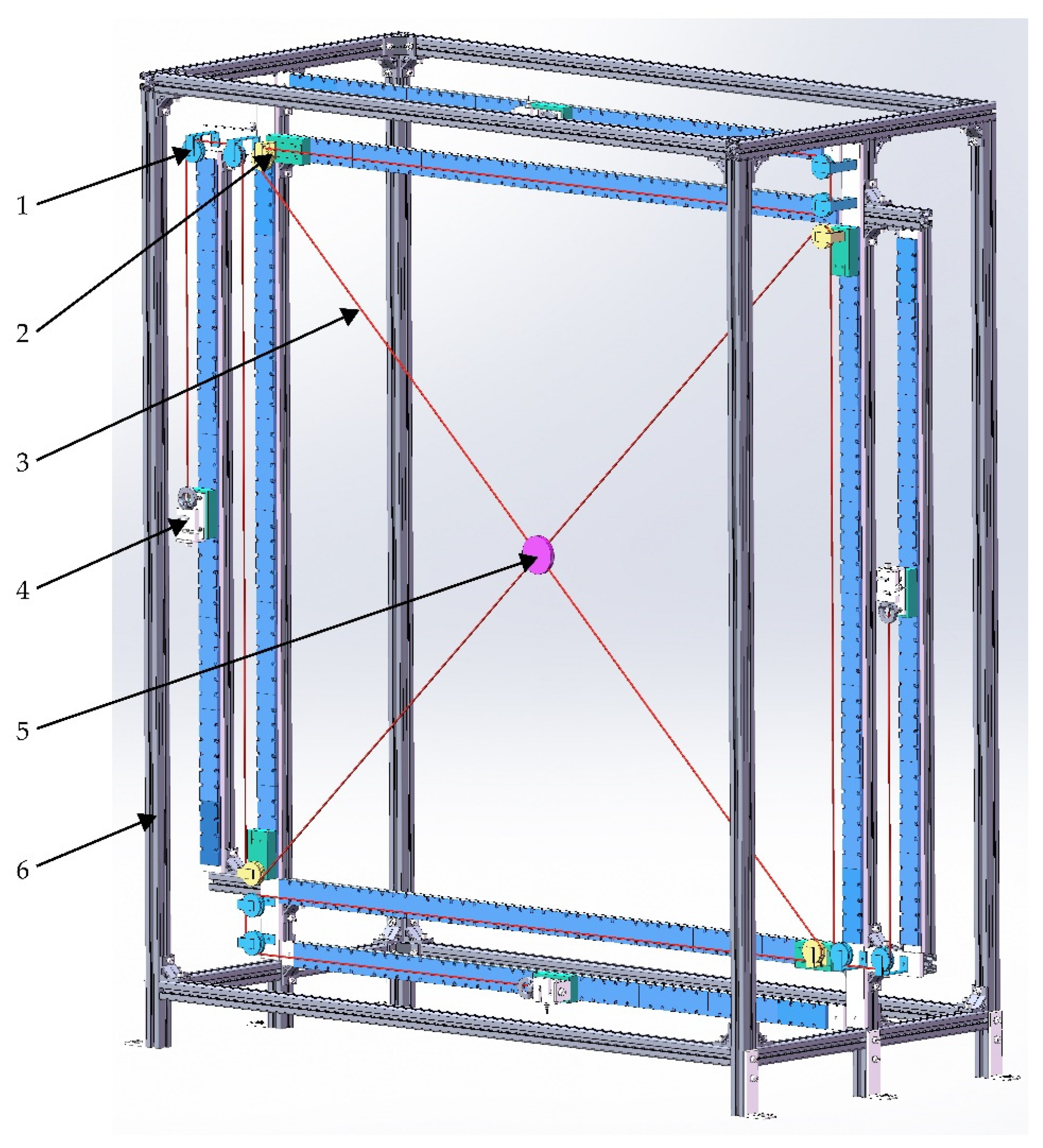
2.1. Static Modelling

Static modeling is the basis of workspace analysis and dynamic modeling in cable-driven parallel mechanisms, and it is very important to ensure the positive tension of the cable. Anson et al. [23] conducted a statics analysis of a 4-cable-driven parallel mechanism with a rectangular base and a circular base and established a static model of the mechanism. Rasheed et al. [24] studied a reconfigurable cable-driven parallel mechanism using a moving base and established static models for the moving platform and the moving base in the mechanism.
The 4-cable-driven parallel mechanism is shown in Figure 1. The 4-cable mechanism is driven by the linear motor to control the 2-DOF movement of the moving platform. The mechanism diagram is shown in Figure 2. Oxy is the global coordinate system, which is fixedly connected to the frame. O’x’y’ is the platform coordinate system, which is fixedly connected to the mass center of the moving platform. A i = [ x A i y A i ] T , i = 1 , 2 , , 4 represents the position vectors of the four pulley exit points in the global coordinate system, respectively, and O = [ x O y O ] T is the position of the moving platform in the global coordinate system.
The analysis of the mechanism shows that the length vector O’Ai of the cable can be expressed as:
L i = A i - O
Thus, the length of the cable is:
l i = L i = ( A i O ) T ( A i O )
Through the force analysis of the moving platform of the 4-cable-driven planar parallel mechanism, because the connections between the four cables and the moving platform are all at its centroid, the moving platform can be regarded as a mass point, and the influence of torque is not taken into account to meet the force balance. The static equation of the cable-driven parallel mechanism is:
i = 1 4 T i + F R = 0
where T i   =   T i l i , Ti represents the tension on the ith cable, l i = L i / L i represents the direction vector of tension on the ith cable, and FR represents the external force on the moving platform, including gravity.
Therefore, Equation (3) can be expressed as:
[ l 1 l 2 l 3 l 4 ] [ T 1 T 2 T 3 T 4 ] = - F R
W = - F R is defined, and Equation (4) can be further simplified as:
J T = W
where
J = [ l 1 l 2 l 3 l 4 ] R 2 × 4
is the structural matrix of the cable-driven parallel mechanism. T = [ T 1 T 2 T 4 ] T R 4 × 1 is the vector of tension amplitude acting on each cable.

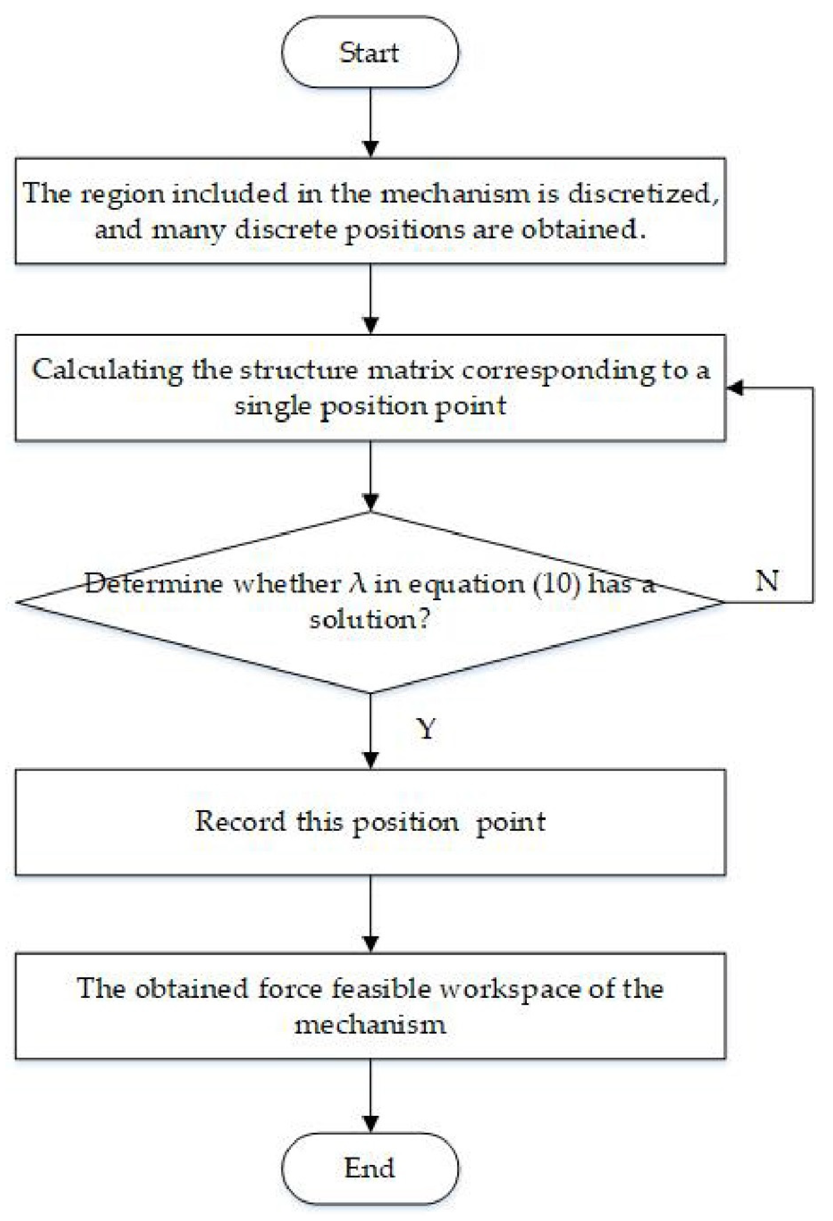
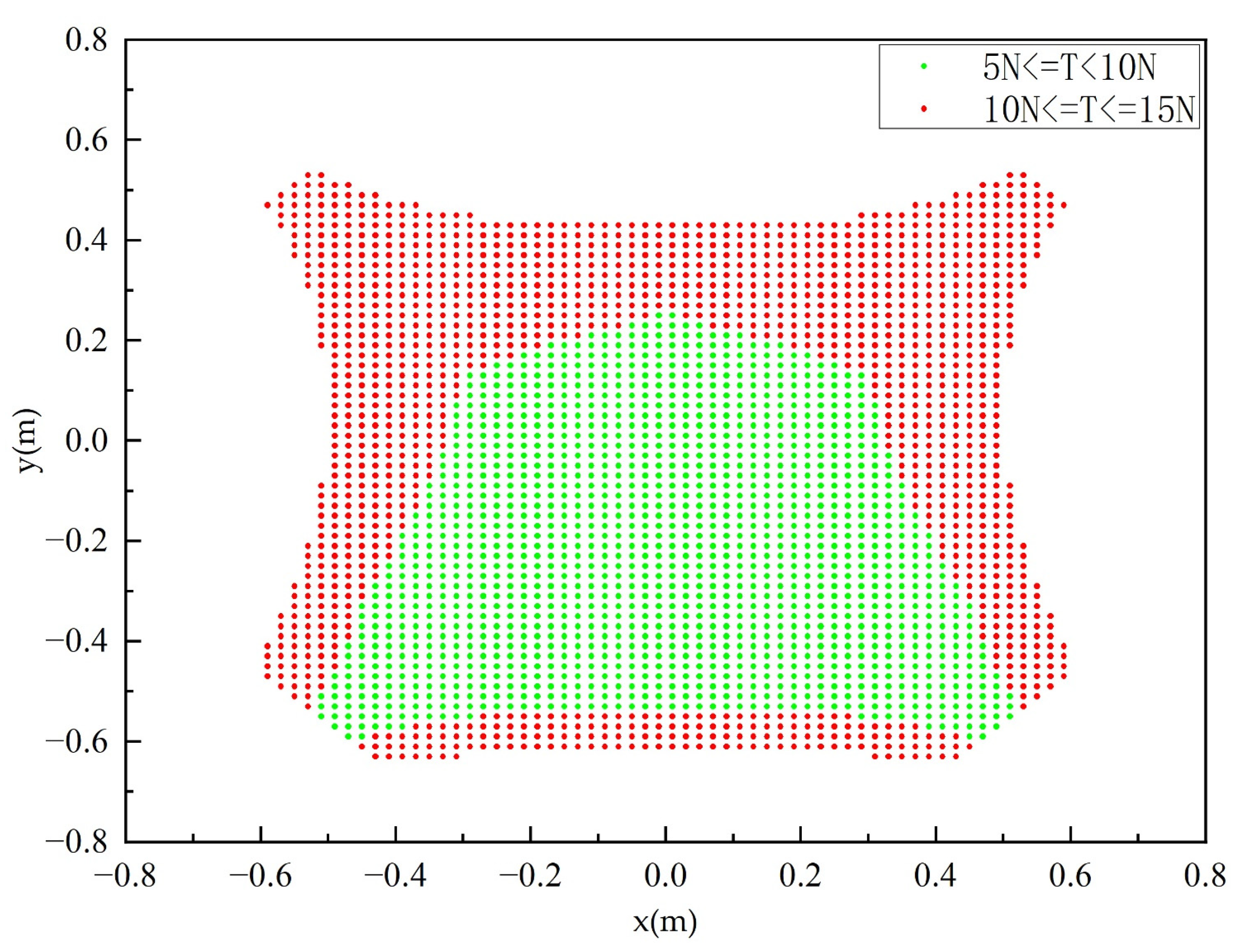
2.2. Workspace Solution Method

The workspace solution is very important for the configuration design and optimization of the cable-driven parallel mechanism. The size of the workspace determines the motion space of the cable-driven parallel mechanism. This section will analyze and solve the feasible workspace of force. In the process of solving the workspace, the static model is used, and the tension of each cable must be between the minimum tension and the maximum breaking force. According to Equation (5), the static model satisfying the cable tension condition can be expressed as:
J T = W 0 < T m i n T i T m a x i = 1 , 2 , , 4
where Tmin and Tmax represent the minimum tension force and maximum breaking force acting on the cable, respectively.
In this paper, the linear motor is used as the driving mechanism, which requires that each cable also has a minimum allowable length lmin and a maximum allowable length lmax; that is:
l m i n l i l m a x i = 1 , 2 , , 4
Because the structural matrix J in Equation (7) is a 2 × 4 dimensional matrix, that is, a non-square matrix, the generalized inverse method is adopted to obtain the following cable tension solution model through Equation (7):
T = J + W + ( I m - J + J ) λ
where J + = J T ( J J T ) - 1 is the Moore–Penrose inverse of the structural matrix J, Im is the four-dimensional identity matrix, λ = [ λ 1 λ 2 λ 3 λ 4 ] T is any 4 × 1 dimension vector, and the size of the cable tension vector T mainly depends on the value of λ.
Let T be between the minimum tension and the maximum breaking force; that is:
T m i n [ 1 1 1 1 ] J + W + ( I m - J + J ) λ T m a x [ 1 1 1 1 ]
Therefore, the solution of the workspace can be transformed into finding the intersection of four linear inequalities with λ as a variable. First, the scope of the workspace of the mechanism is selected. Then, all discrete points within the scope are judged. If the inequality in Equation (10) has a solution at the same time, the point is considered to be located in the workspace. The flow chart of the solution algorithm is shown in Figure 3 below. Using this method, the force-feasible workspace of the parallel mechanism can be obtained quickly and conveniently.

2.3. Solution Method of Cable Tension under Typical Trajectory

2.3.1. Solution Method of Cable Tension

As for the force analysis of the moving platform of the parallel mechanism shown in Figure 2, the dynamic equation of the mechanism can be obtained as:
J T + F R = M a
where a = [ a x a y ] T is the acceleration of the moving platform.
For the redundantly constrained (i.e., m > n + 1 , where m is the number of cables and n is the number of degrees of freedom) cable-driven parallel mechanism, because the number of rows of its structure matrix is less than the number of columns, it is a non-square matrix. After a given load, there are multiple feasible cable tensions corresponding to each pose point of the moving platform. However, in the actual motion control of the parallel mechanism, it is necessary to obtain a unique solution for the tension of each cable, so the tension solution of the cable must be analyzed.
The 4-cable-driven 2-DOF parallel mechanism studied in this paper is a redundant constraint mechanism, and the cable tension solution at each position should satisfy the dynamics expressions (11) under its motion trajectory. Therefore, the mechanism dynamics model can be expressed as:
J T + F R = M a 0 < T m i n T i T m a x i = 1 , 2 , , 4
According to the quadratic programming theory and an improved quadratic programming solution model by Tao et al. [25], to solve the cable tension, we use the following formula:
min   F ( T ) = 1 2 ( T - T r e f ) T Q ( T - T r e f ) s . t . J T + F R = M a 0 < T m i n T i T m a x i = 1 , 2 , , 4
where Q is the fourth-order identity matrix and T r e f = t r e f [ 1 1 1 1 ] T is the introduced reference force, which is mainly determined by the minimum pre-tightening force and the maximum breaking force of the cable, namely:
t r e f = 1 2 ( T m i n + T m a x )

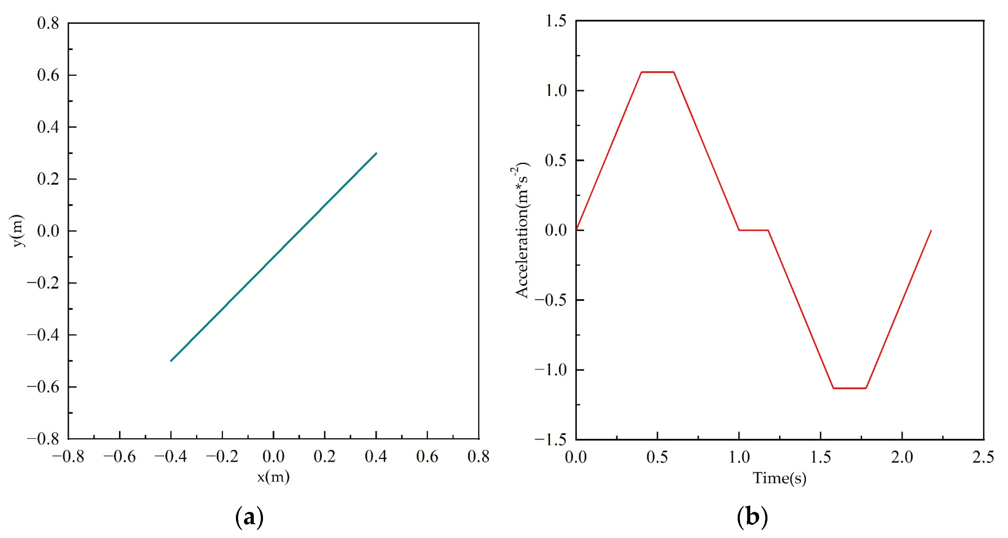
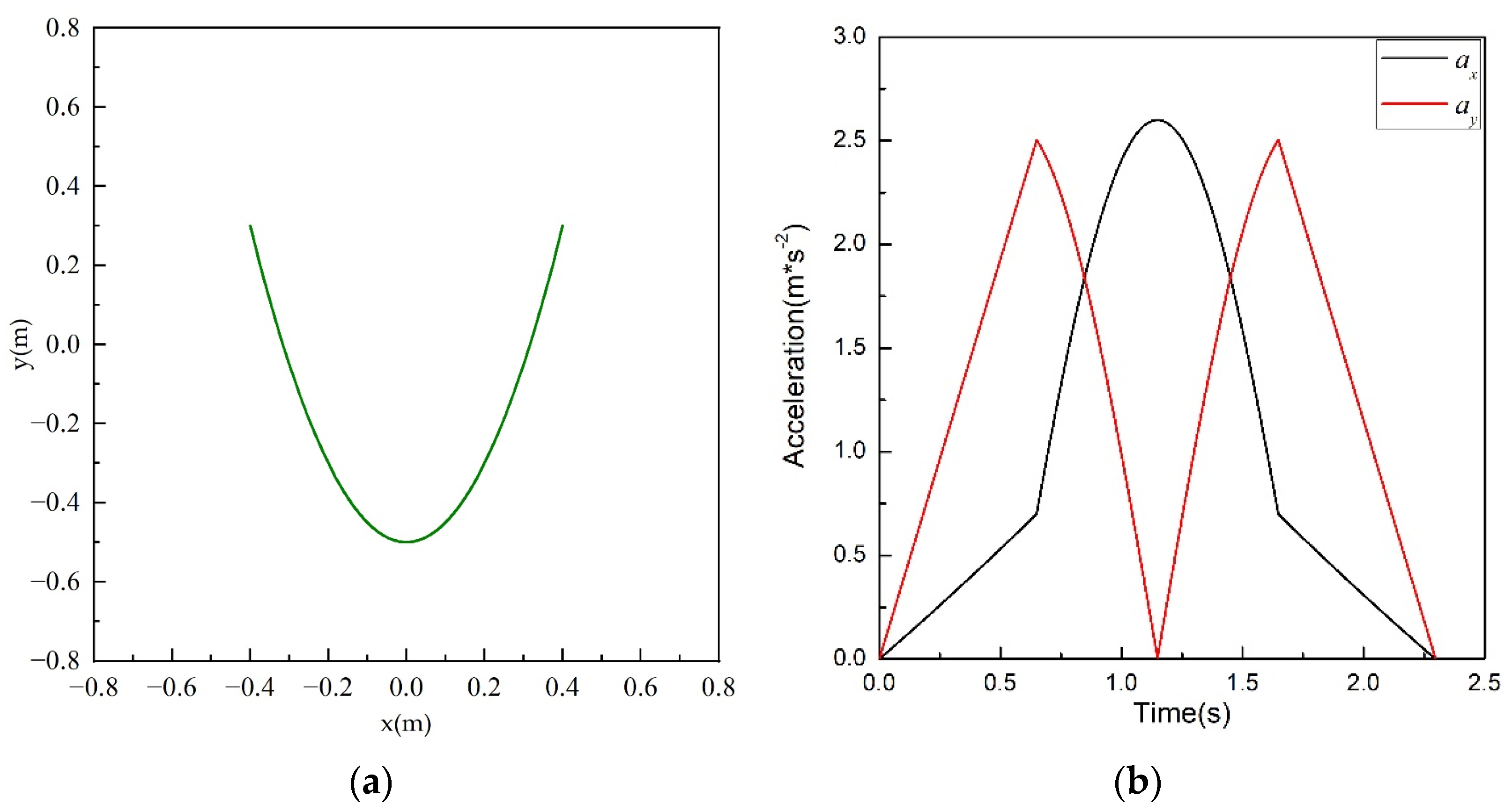
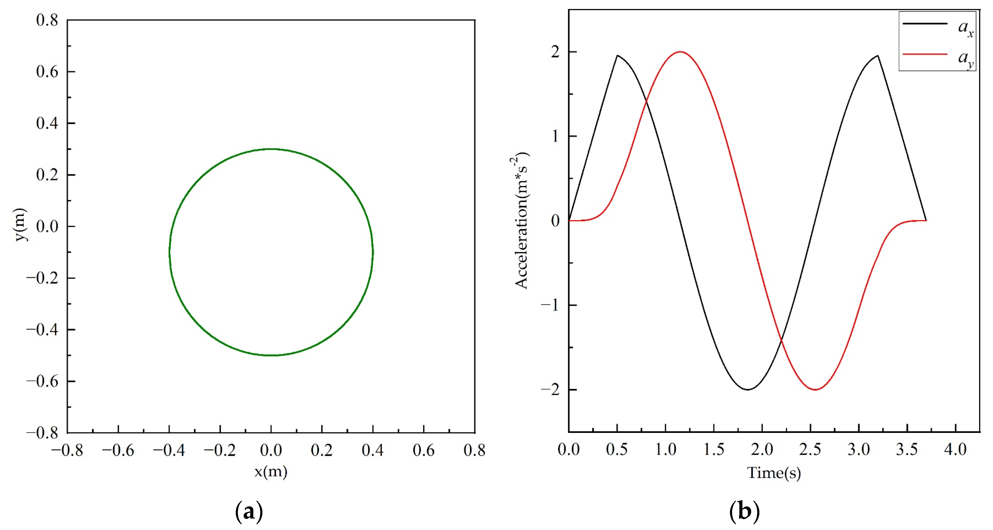
2.3.2. Three Typical Trajectories in the Workspace

The trajectory of the moving platform is always the focus of research on the parallel mechanism. By realizing the trajectory of the parallel mechanism in the plane, research on the kinematics and dynamics of the parallel mechanism can be completed. In this section, for a 4-cable-driven 2-DOF parallel mechanism, the cable tension of three paths in the force-feasible workspace solved in the previous section is solved based on the dynamic model.
Figure 4a shows the linear motion trajectory of the moving platform, which can be expressed as:
y = x 0.1
Starting from (−0.4, −0.5), the moving platform moves according to the acceleration curve shown in Figure 4b, and reaches the terminal coordinates (0.4, 0.3).
Figure 5a shows the parabolic motion trajectory of the moving platform, which can be expressed as:
y = 5 x 2 0.5
The moving platform starts from (−0.4, 0.3) as the coordinate point. It moves according to the acceleration curve shown in Figure 5b, and reaches the terminal coordinates (0.4, 0.3).
Figure 6a shows the circular motion trajectory of the moving platform, which can be expressed as:
{ x = 0.4 × c o s θ y = 0.1 + 0.4 × s i n θ
where θ is the angular displacement of the moving platform. Starting from (−0.4, −0.1), the moving platform moves in a counterclockwise direction according to the acceleration curve shown in Figure 6b for one circle, reaching the end coordinate (0.4, 0.1).
The acceleration curves in Figure 4b, Figure 5b and Figure 6b are the acceleration of the moving platform in the x and y directions, respectively. Figure 4b is the acceleration curve of the moving platform in a straight line, and the angle between the moving track and the horizontal right direction is 45 degrees, so the acceleration curves in the x and y directions coincide completely.

2.4. Exit Point Trajectory Planning

According to the calculation results of the cable tension under the fixed exit point in the previous section, in order to further reduce the variation in cable tension, this section explores adopting the method of changing the configuration of the parallel mechanism to control the variation uniformity of the cable tension. In this paper, the main consideration is to change the position of the pulley connected with the cable on the mechanism frame, that is, the position of the exit point. When other structural parameters remain unchanged, the problem of the uniform change in tension of the control for the cable-driven parallel mechanism can be simplified to plan the position of the exit point so that the uniform change in the parallel mechanism’s cable tension can be made more evenly.
In the cable-driven parallel mechanism, the structure matrix J as the main parameter is used to represent the cable tension force and moment of platform movement and transitive relation. In this article, J is mainly the exit point location and the parameters of the moving platform location decision. Thus, the exit point location in the body will directly affect the size of the cable-driven parallel mechanism’s cable tension change. As can be seen from the parallel mechanism structure shown in Figure 2, the pulleys of the exit points can only move in the direction of the frame in which they are located, that is, they can only move one-dimensionally. The positions of the four exit points—A1, A2, A3, and A4—can be expressed as ( a 1 , y A 1 ) , ( x A 2 , a 2 ) , ( a 3 , y A 3 ) , and ( x A 4 , a 4 ) , respectively, in the global coordinate system Oxy, where a1 and a3 are the abscess values of A1 and A3 of the exit points, respectively, and a2 and a4 are the ordinate values of A2 and A4 of the exit points, respectively. When the moving platform moves along the track, the corresponding A1 to A4 values at each moment are fitted onto a smooth curve, which is the track planning curve of the four exit points. Other values in the coordinates are determined by the frame size of the parallel mechanism and are invariants all the time.
Therefore, based on the dynamic equation in Equation (11) and the quadratic programming model, the following location trajectory planning model of the exit points is given:
min   F ( J T ) = 1 2 ( J T ) T Q J T s . t . T T J T = ( M a ) T - F R T
where T = [ t 1 t 2 t 3 t 4 ] T is constant when JT is solved and t i = 1 2 ( t i - m i n + t i - m a x ) , I = 1,2,3,4, ti-min and ti-max are shown as the minimum and maximum values of the tension changes in the four cables corresponding to each trajectory.
First, the JT corresponding to each moment of the three kinds of trajectory is solved by the trajectory planning model (18). Then, the values A1 to A4 of the position of the exit point at each moment can be obtained according to Equation (6), and the trajectory planning curves of the four exit points can be obtained. The Equation (6) can be specifically expressed as:
J = [ a 1 x ( a 1 x ) ^ 2 + ( 0.76 y ) ^ 2 0.76 x ( 0.76 x ) ^ 2 + ( a 2 y ) ^ 2 a 3 x ( a 3 x ) ^ 2 + ( 0.76 y ) ^ 2 0.76 x ( 0.76 x ) ^ 2 + ( a 4 y ) ^ 2 0.76 y ( a 1 x ) ^ 2 + ( 0.76 y ) ^ 2 a 2 y ( 0.76 x ) ^ 2 + ( a 2 y ) ^ 2 0.76 y ( a 3 x ) ^ 2 + ( 0.76 y ) ^ 2 a 4 y ( 0.76 x ) ^ 2 + ( a 4 y ) ^ 2 ]
For the trajectory of straight lines, parabolas, and circles, T = [ 9.5 10.5 9 9 ] T , T = [ 10 10 9 9 ] T , and T = [ 10 10 9 9 ] T can be calculated, respectively.

3. Results and Discussion

3.1. Workspace Solution Results

According to the schematic diagram of the mechanism shown in Figure 2, the feasible workspace of force under the fixed exit point was calculated, wherein the frame is a square with a side length of 1.53 m; A1 to A4 are the four fixed exit points; and the coordinates are (−0.76 m, 0.76 m), (0.76 m, 0.76 m), (0.76 m, −0.76 m) and (−0.76 m, −0.76 m), respectively, in the global coordinate system Oxy. The moving platform is circular with a radius of 0.04 m. The connection points of the four cables and the moving platform are all at their centroid. In the initial state, the coordinates in the global coordinate system Oxy are (0, 0). The search conditions for workspace solution are shown in Table 1.
Assuming that the resultant external force acting on the moving platform is only its gravity, F R = M g , where M = [ m 0 0 m ] is the mass of the moving platform and g = [ 0 - g ] T , namely, W = [ 0 m g ] T . In this paper, m = 0.3   kg , g = 10   m / s 2 are selected according to the actual design requirements.
According to the search conditions listed in Table 1, the four linear inequalities in Equation (10) were solved, and the λ values satisfying the constraint conditions were determined. The workspace of the cable-driven parallel mechanism in Figure 2 was obtained, as shown in Figure 7. The number of points contained in the feasible workspace of force was 2922. Figure 8 shows the cable tension distribution at each discrete point in the force-feasible workspace, in which the green point indicates that the tension of all four cables is between 5 N and 10 N, and the red point indicates that the maximum tension of all four cables is between 10 N and 15 N, and the tension of the other cables is always between 5 N and 15 N.

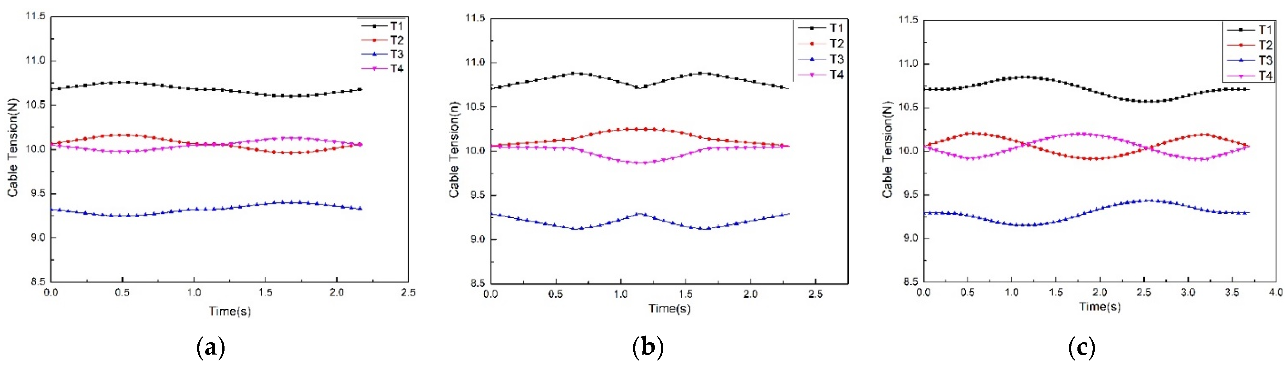
3.2. Solution Result of Cable Tension under Typical Trajectory in Workspace

The moving platform moves according to the track and planned acceleration shown in Figure 4, Figure 5 and Figure 6. Equation (13) is used to calculate the cable tension of the three motion tracks, and the tension curve of the four cables as it changes with time is obtained, as shown in Figure 9.
According to the calculation results of cable tension in the fixed configuration, the change degree of cable tension is expressed by the standard deviation. The maximum standard deviation of cable tension in the four cables in the straight track is 3.0063 N, that in the parabolic track is 3.0446 N, and that in the circular track is 2.8665 N. According to the analysis of the cable tension curve in Figure 9, the cable tension of the cable-driven parallel mechanism in a fixed configuration can be solved by the improved quadratic programming algorithm proposed above, and the cable tension can be within a given range under three trajectories of straight line, parabola, and circle. However, the cable tension changes greatly and is close to the allowable limit value of cable tension at some time, so the risk of cable breakage is high, which is not conducive to the safe operation of the mechanism.

3.3. Trajectory Planning Result of the Exit Point

The corresponding trajectory planning curves of the exit point can be solved as shown in Figure 10, in which the motion curves of the exit point position a1 and a3 basically coincide.
To verify the control effect of continuous change in cable tension on uniform change by changing the position of the exit point, Equation (13) can be used to solve the cable tension under a change in the exit point position. The obtained cable tension change curve is shown in Figure 11.
From the analysis of the curve in Figure 10, according to the trajectory planning model of the exit point proposed in this paper, the trajectory curves of the exit pulley corresponding to the linear, parabolic, and circular trajectories of the moving platform can be obtained; the pulley motion is always within the size of the mechanism frame. From the analysis of the tension curves of four cables corresponding to the three trajectories in Figure 11, it can be seen that the maximum standard deviation of the four cables in the straight trajectory is 0.0645 N, the maximum standard deviation of the cable tension in the parabolic trajectory is 0.0639 N, and the maximum standard deviation of the cable tension in the circular trajectory is 0.0941 N. When the pulley at the cable outlet moves along the planned trajectory, the obtained cable tension value changes continuously within the minimum range of the set size, that is, the linear motor can output a stable tension, thus avoiding cable jitter to the greatest extent and ensuring the movement accuracy and stability of the moving platform.
Cable tension optimization is an important research content of a reconfigurable cable-driven parallel mechanism. The result of cable tension optimization of a reconfigurable cable-driven parallel mechanism proposed in [21] is that the cable tension value changes between 0.5 N and 7 N, and the cable tension value changes greatly in this paper and fluctuates greatly in the process of the movement of the moving platform. The result of cable tension optimization allocation of a planar movable cable-driven parallel mechanism proposed in [22] is that the cable tension value changes between 15 N and 200 N, which intuitively shows that the cable tension varies in a relatively large range. In this paper, the difference between the maximum and minimum tension on each cable is less than 0.5 N by planning the exit point trajectory, and the tension curve changes smoothly. Compared with the cable tension optimization results in [21,22], it can be seen that the method proposed in this paper has a better effect.

4. Conclusions

A reconfigurable cable-driven parallel mechanism was proposed in which the position of the exit point could be continuously changed. An exit pulley was installed on the linear motor, and the configuration of the mechanism could be changed during the movement of the moving platform through the cooperation of multiple motors.
Considering the constraints of cable length and tension, a simple and fast method to solve the force-feasible workspace was proposed for a cable-driven parallel mechanism with fixed exit points, and the cable tension in the workspace was solved based on an improved quadratic programming model. The maximum standard deviations of cable tension under the three trajectories of straight line, parabola, and circle are 3.0063 N, 3.0446 N and 2.8665 N, respectively.
A method for the trajectory planning of exit points was presented, and the trajectory planning curves of exit points under different trajectories were obtained. According to the values of the exit points at each moment, the cable tension during the movement of the platform can be solved. The maximum standard deviations of cable tension under three trajectories of straight line, parabola, and circle in reconfigurable configuration are 0.0645 N, 0.0639 N, and 0.0941, respectively. From the results, it can be seen that the change range of cable tension can be greatly reduced after the trajectory planning of the exit point.
Based on the above research results, the driving force required for motor control can be further studied. At the same time, the motion relationship between the motor driving the cable movement and the motor driving the pulley movement can be studied to ensure the motion accuracy of the moving platform. Finally, because this paper only analyzed the reconfigurable parallel mechanism theoretically, it suggests that the software control method of reconfigurable parallel mechanisms should be studied in the next step.

Author Contributions

Conceptualization, C.P. and H.L.; methodology, C.P.; software, C.P.; validation, C.P., H.L., F.Y. and Z.H.; formal analysis, C.P.; investigation, C.P.; resources, Y.L.; data curation, C.P.; writing—original draft preparation, C.P.; writing—review and editing, H.L. and Y.L.; visualization, C.P. and H.L.; supervision, H.L. and F.Y.; project administration, Y.L.; funding acquisition, Z.H. All authors have read and agreed to the published version of the manuscript.

Funding

This research was funded in part by the National Basic Scientific Research Project of China, grant number JCKY2019419D001; in part by the Scientific and Technological Key Project of Henan Province, grant number 202102210078; and in part by the Key Scientific Research Projects of Colleges and Universities of Henan Province, grant number 19A460017.

Institutional Review Board Statement

Not applicable.

Informed Consent Statement

Not applicable.

Data Availability Statement

The date presented in this study are available in the article.

Conflicts of Interest

The authors declare no conflict of interest.

Glossary

SymbolMeaningSymbolMeaning
AiThe position vector of the ith exit point in the global coordinate systemgAcceleration of gravity
OThe position of the platform in the global coordinate systemaThe acceleration of the moving platform
LiThe length vector of the ith cablemThe number of cables
TiThe tension vector of the ith cablenThe number of degrees of freedom
TiThe tension of the ith cableQThe fourth-order identity matrix
liUnit vector of the ith cable tensionTrefReference force
FRExternal force of moving platformθThe angular displacement of the moving platform
JForce Jacobian matrixa1The abscess value of A1 of the exit point
ImFour-dimensional identity matrixa2The ordinate values of A2 of the exit point
λAny 4 × 1 dimension vectora3The abscess value of A3 of the exit point
MThe mass of the moving platforma4The ordinate values of A4 of the exit point

References

  1. Lei, Y.Z. Recent research advances and expectation of mechanical engineering science in China. J. Mech. Eng. 2009, 45, 1–11. [Google Scholar] [CrossRef]
  2. Zi, B.; Cao, J.B.; Zhu, Z.C.; Mitrouchev, P. Design, dynamics, and workspace of a hybrid-driven-based cable parallel manipulator. Math. Probl. Eng. 2013, 2013, 914653. [Google Scholar] [CrossRef] [Green Version]
  3. Qian, S.; Zi, B.; Shang, W.W.; Xu, Q.S. A review on cable-driven parallel robots. J. Mech. Eng. 2018, 31, 37–47. [Google Scholar] [CrossRef]
  4. Yang, Q.G.; Zhu, W.B. Mechanical design of the six-cable driven parallel mechanism in FAST telescope. Int. Conf. Control Autom. 2016, 11, 320–325. [Google Scholar] [CrossRef] [Green Version]
  5. Yao, R.; Tang, X.Q.; Wang, J.S.; Huang, P. Dimensional optimization design of the four-cable-driven parallel manipulator in FAST. IEEE ASME Trans. Mechatron. 2010, 15, 932–941. [Google Scholar] [CrossRef]
  6. Wang, X.G.; Hu, Y.B.; Lin, Q. Workspace analysis and verification of cable-driven parallel mechanism for wind tunnel test. Proc. Inst. Mech. Eng. Part G 2016, 231, 1012–1021. [Google Scholar] [CrossRef]
  7. Chen, Q.L.; Lin, Q. Analysis on metamorphic of the cable-driven parallel mechanism in wind tunnel test. Appl. Mech. Mater. 2013, 336–338, 1196–1203. [Google Scholar] [CrossRef]
  8. Wu, H.S.; Lin, Q.; Wang, X.G.; Ji, Y.F.; Peng, M.J. Design and kinematic analysis of cable-driven parallel mechanism for helicopter model in formation flight. In Proceedings of the IEEE CSAA Guidance, Navigation and Control Conference (CGNCC), Xiamen, China, 10–12 August 2018; p. 9018979. [Google Scholar]
  9. Abbasnejad, G.; Yoon, J.; Lee, H. Optimum kinematic design of a planar cable-driven parallel robot with wrench-closure gait trajectory. Mech. Mach. Theory 2016, 99, 1–18. [Google Scholar] [CrossRef]
  10. Hamida, I.B.; Laribi, M.A.; Mlika, A.; Romdhane, L.; Carbone, G. Multi-Objective optimal design of a cable driven parallel robot for rehabilitation tasks. Mech. Mach. Theory 2021, 156, 104141–104164. [Google Scholar] [CrossRef]
  11. Shi, P.S.; Tang, L.W. Dimensional synthesis of a gait rehabilitation cable-suspended robot on minimum 2-norm tensions. J. Mech. Med. Biol. 2021, 21, 2150046. [Google Scholar] [CrossRef]
  12. Izard, J.B.; Dubor, A.; Hervé, P.E.; Cabay, E.; Culla, D.; Rodriguez, M.; Barrado, M. Large-scale 3D printing with cable-driven parallel robots. Constr. Robot. 2017, 1, 69–76. [Google Scholar] [CrossRef]
  13. Qian, S.; Bao, K.L.; Zi, B.; Wang, N. Kinematic calibration of a cable-driven parallel robot for 3D printing. Sensors 2018, 18, 2898. [Google Scholar] [CrossRef] [Green Version]
  14. Tho, T.P.; Thinh, N.T. Using a Cable-Driven Parallel Robot with applications in 3D concrete printing. Appl. Sci. 2021, 11, 563. [Google Scholar] [CrossRef]
  15. Nguyen, D.Q.; Gouttefarde, M.; Company, O.; Pierrot, F. On the analysis of large-dimension reconfigurable suspended cable-driven parallel robots. In Proceedings of the IEEE International Conference on Robotics and Automation, Hong Kong, China, 31 May–7 June 2014; pp. 5728–5735. [Google Scholar]
  16. Barbazza, L.; Oscari, F.; Minto, S.; Rosati, G. Trajectory planning of a suspended cable driven parallel robot with reconfigurable end effector. Robot. Comput.-Int. Manuf. 2017, 48, 1–11. [Google Scholar] [CrossRef]
  17. Duan, Q.J.; Duan, X.C. Workspace classification and quantification calculations of cable-driven parallel robots. Adv. Mech. Eng. 2014, 6, 1–9. [Google Scholar] [CrossRef] [Green Version]
  18. Ouyang, B.; Shang, W.W. Rapid optimization of tension distribution for cable-driven parallel manipulators with redundant cables. Chin. J. Mech. Eng. 2016, 29, 231–238. [Google Scholar] [CrossRef]
  19. Zhang, F.; Shang, W.W.; Zhang, B.; Cong, S. Design optimization of redundantly actuated cable-driven parallel robots for automated warehouse system. IEEE Access 2020, 8, 56867–56879. [Google Scholar] [CrossRef]
  20. Zhang, Z.; Liang, Y.Y.; Liu, H.W.; Wang, X.J. The research of optimal tension distribution methods based on typical trajectory. Mach. Des. Manuf. 2016, 4, 35–38, 43. [Google Scholar]
  21. Masone, C.; Bulthoff, H.H.; Stegagno, P. Cooperative transportation of a payload using quadrotors: A reconfigurable cable-driven parallel robot. In Proceedings of the IEEE/RSJ International Conference on Intelligent Robots and Systems (IROS), Daejeon, Korea, 9–14 October 2016; pp. 1623–1630. [Google Scholar]
  22. Rasheed, T.; Long, P.; Marquez-Gamez, D.; Caro, S. Tension distribution algorithm for planar mobile cable-driven parallel robots. Mech. Mach. Sci. 2018, 53, 268–279. [Google Scholar]
  23. Anson, M.; Alamdari, A.; Krovi, V. Orientation workspace and stiffness optimization of cable-driven parallel manipulators with base mobility. J. Mech. Rob. 2017, 9, 031011. [Google Scholar] [CrossRef]
  24. Rasheed, T.; Long, P.; Caro, S. Wrench-feasible workspace of mobile cable-driven parallel robots. J. Mech. Rob. 2019, 12, 1–23. [Google Scholar] [CrossRef] [Green Version]
  25. Tao, Y.; Zhang, S.Y.; Wang, Y.W. Research of tension distribution solution for redundantly constrained cable-driven parallel robots. Mech. Sci. Technol. Aerosp. Eng. 2021, 40, 344–349. [Google Scholar]
Figure 1. The four-cable-driven parallel mechanism with (1) a guide pulley mechanism (four groups), (2) a movable pulley mechanism (four groups), (3) a flexible cable (four pieces), (4) a linear motor (four groups), (5) a circular moving platform, and (6) a parallel mechanism frame.
Processes 10 01544 g001
Figure 2. Model diagram of the four-cable-driven parallel mechanism.
Processes 10 01544 g002
Figure 3. Solution algorithm flow of force-feasible workspace.
Processes 10 01544 g003
Figure 4. Linear motion trajectory and acceleration of moving platform. (a) Motion trajectory; (b) Acceleration curve.
Processes 10 01544 g004
Figure 5. Parabolic motion trajectory and acceleration of moving platform. (a) Motion trajectory; (b) Acceleration curve.
Processes 10 01544 g005
Figure 6. Parabolic motion trajectory and acceleration of moving platform. (a) Motion trajectory; (b) Acceleration curve.
Processes 10 01544 g006
Figure 7. The force-feasible workspace of the four-cable-driven parallel mechanism.
Processes 10 01544 g007
Figure 8. Tension distribution in force-feasible workspace.
Processes 10 01544 g008
Figure 9. Cable tension–time curve of (a) linear motion trajectory, (b) parabolic motion trajectory, and (c) circular motion trajectory.
Processes 10 01544 g009
Figure 10. The trajectory planning curves of the exit point under (a) linear motion trajectory, (b) parabolic motion trajectory and (c) circular motion trajectory.
Processes 10 01544 g010
Figure 11. Variation curve of cable tension under continuous change in cable exit point position. (a) Linear motion trajectory; (b) Parabolic motion trajectory; (c) Circular motion trajectory.
Processes 10 01544 g011
Table 1. Workspace search condition parameters.
Search Condition ParametersValue
Cable tension range/N[5,15]
x direction search range/m[−0.75, 0.75]
y direction search range/m[−0.75, 0.75]
Minimum allowable length of cable lmin/m0.1
Maximum allowable length of cable lmax/m1.85
Search step/m0.02
Publisher’s Note: MDPI stays neutral with regard to jurisdictional claims in published maps and institutional affiliations.

