
Analysis and Application of Horizontal Well Test in Low Permeability Porous Carbonate Reservoir

Abstract
:
1. Introduction
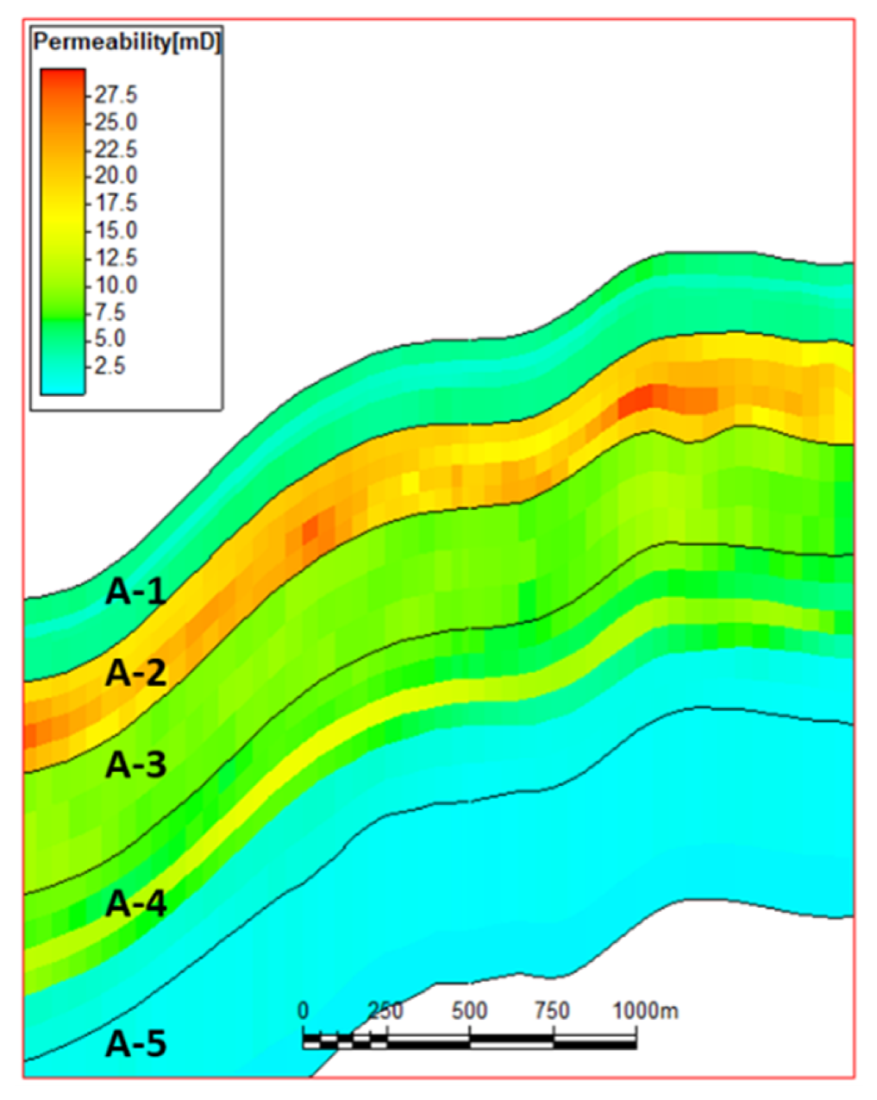
2. Geologic Reservoir Characteristic
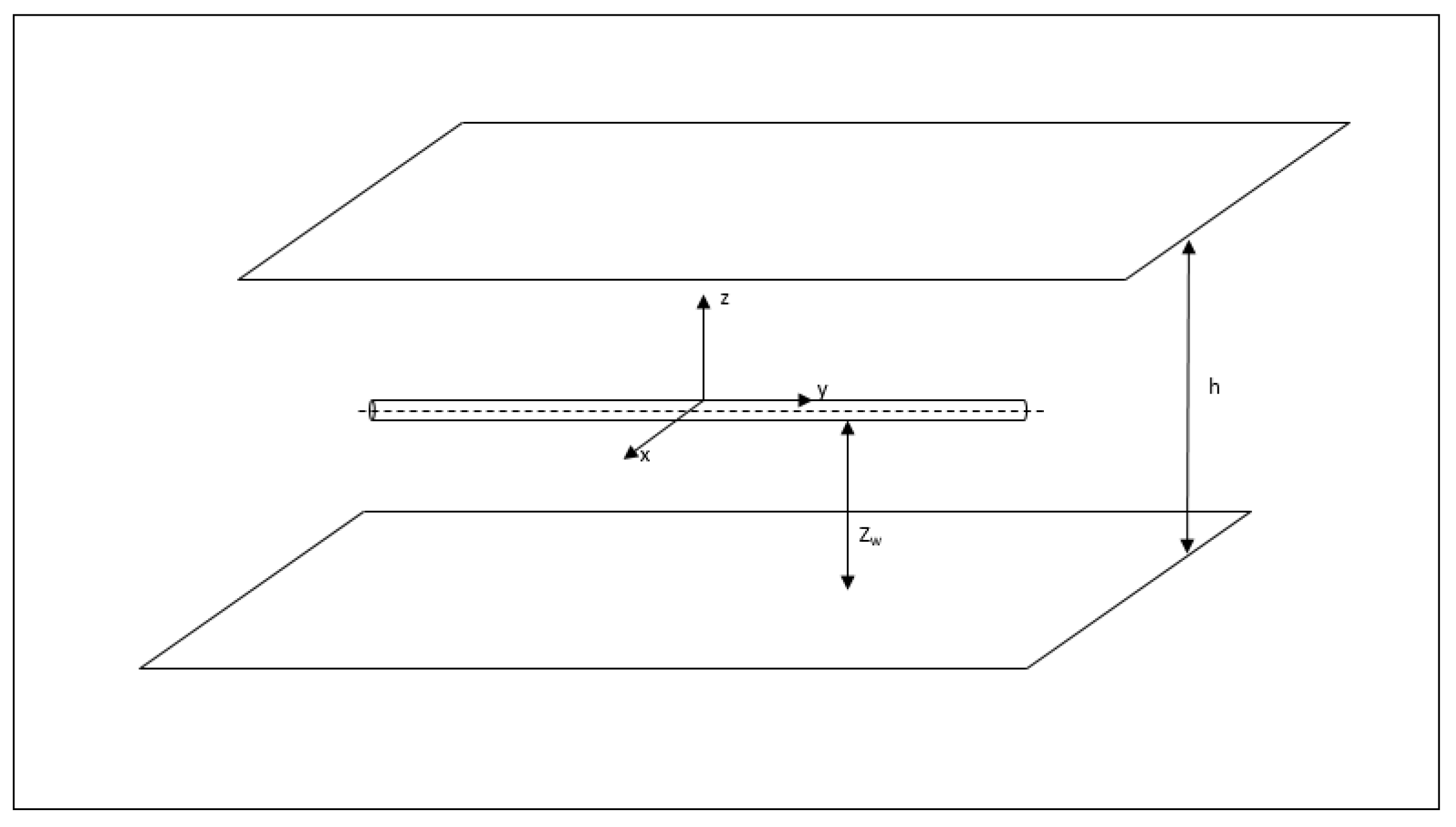
3. Horizontal Well Test Mathematical Model
- = Vertical permeability, mD
- = Horizontal permeability, mD
- = Permeability anisotropy ratio
- L = Half length of horizontal wells, ft
- = Dimensionless half length of horizontal wells
- = Horizontal pressure diffusivity
- = Vertical pressure diffusivity
- = Reservoir thickness, ft
- = Normalized h, from uniform anisotropic medium to uniform isotropic medium
- = Dimensionless normalized h
- = Pressure, psi
- = Initial pressure, psi
- = Dimensionless pressure
- = Flow rate, stb/d
- = Dimensionless wellbore radius
- = Wellbore radius, ft
- = Laplace transform variable
- = Skin
- = Time, h
- = Dimensionless time
- = Coordinate, ft
- = Midpoint coordinates in horizontal segment, ft
- = Dimensionless coordinate
- = Coordinate, ft
- = Midpoint coordinates in horizontal segment, ft
- = Dimensionless coordinate
- = Coordinate, ft
- = Dimensionless coordinate
- = Height of horizontal section above bottom surface, ft
- = Dimensionless height of horizontal section above bottom surface, ft
- = Normalize z, from uniform anisotropic medium to uniform isotropic medium
- = Porosity, dimensionless
- = Fluid viscosity, cp
- = Composite compressibility, 1/psi
- = Formation volume coefficient
- = Dimensionless wellbore storage coefficient,
- = Image function of bottom hole pressure
- = error function
4. Well Test Curve Characteristics of Low Permeability Carbonate Reservoir
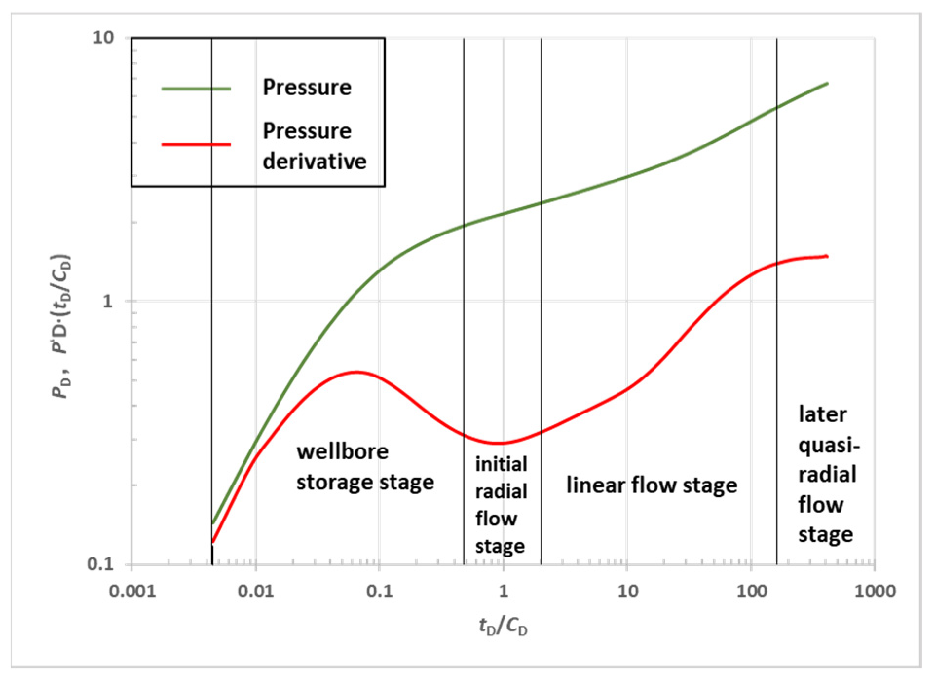
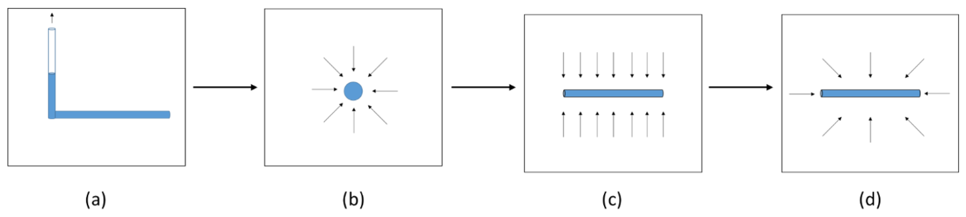
4.1. Typical Horizontal Well Test Curve
- Wellbore storage stage;
- Initial radial flow stage;
- Linear flow stage;
- Later quasi-radial flow stage;
4.2. Influencing Factors of Well Test Curve Characteristics
4.3. Well Test Curve Characteristics of Low Permeability Carbonate Reservoir
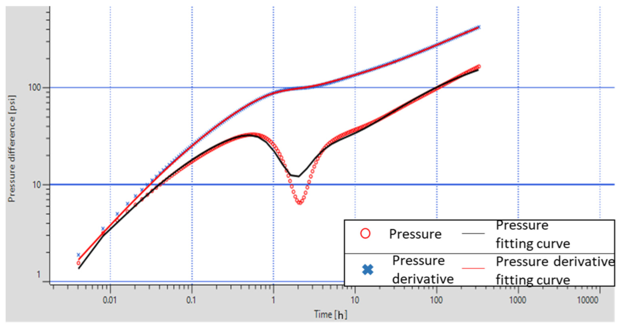
- There is no radial flow stage in the well test curves:The permeability of the main reservoir in the study area is low, and the permeability is 10 mD. At the same time, the development of the white spot section in the reservoir hinders the migration of the fluid, resulting in low pressure conductivity of the reservoir, slow water injection efficiency, and inability to achieve radial flow during the test time.
- Characteristics of variable well storage:The characteristics of changing wellbore storage mainly appear in the well test curve of production wells. Low permeability reservoirs generally have the characteristics of variable well storage. In the water injection development area, there is a multiphase flow in the wellbore. Shutdown for a period of time will redistribute the phase in the wellbore, resulting in a decrease in the fluid compression coefficient and a decrease in the wellbore storage coefficient.
- Double logarithmic curve opening is small:Reservoir A has good formation conditions and no pollution blockage exists. Reflected in the well test curve, the explanatory skin coefficient parameter is negative, and the opening of the double logarithmic curve is small.
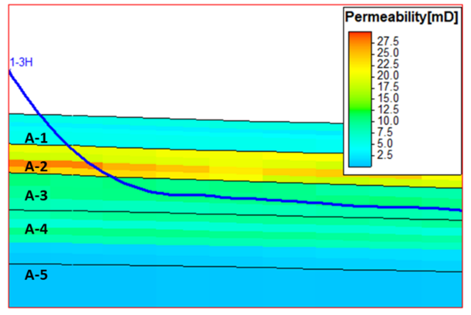
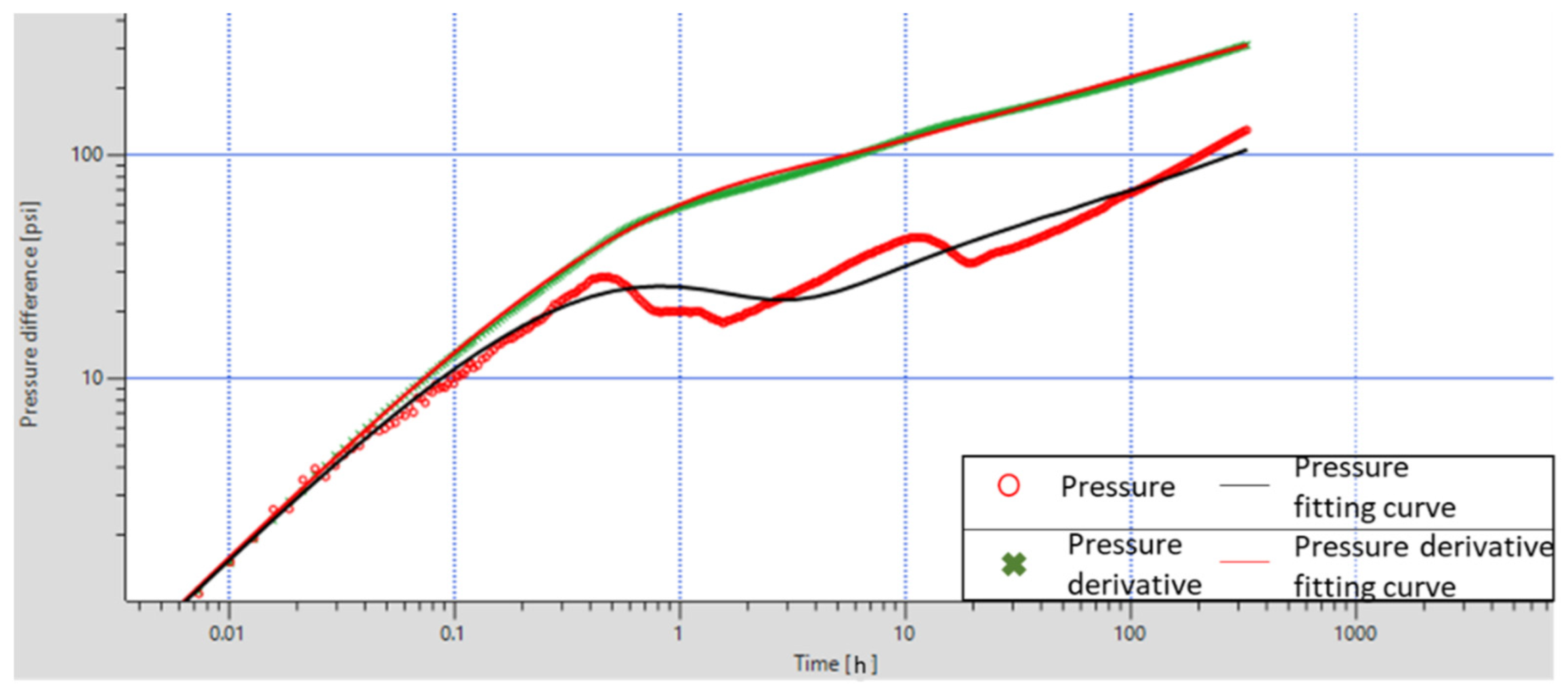
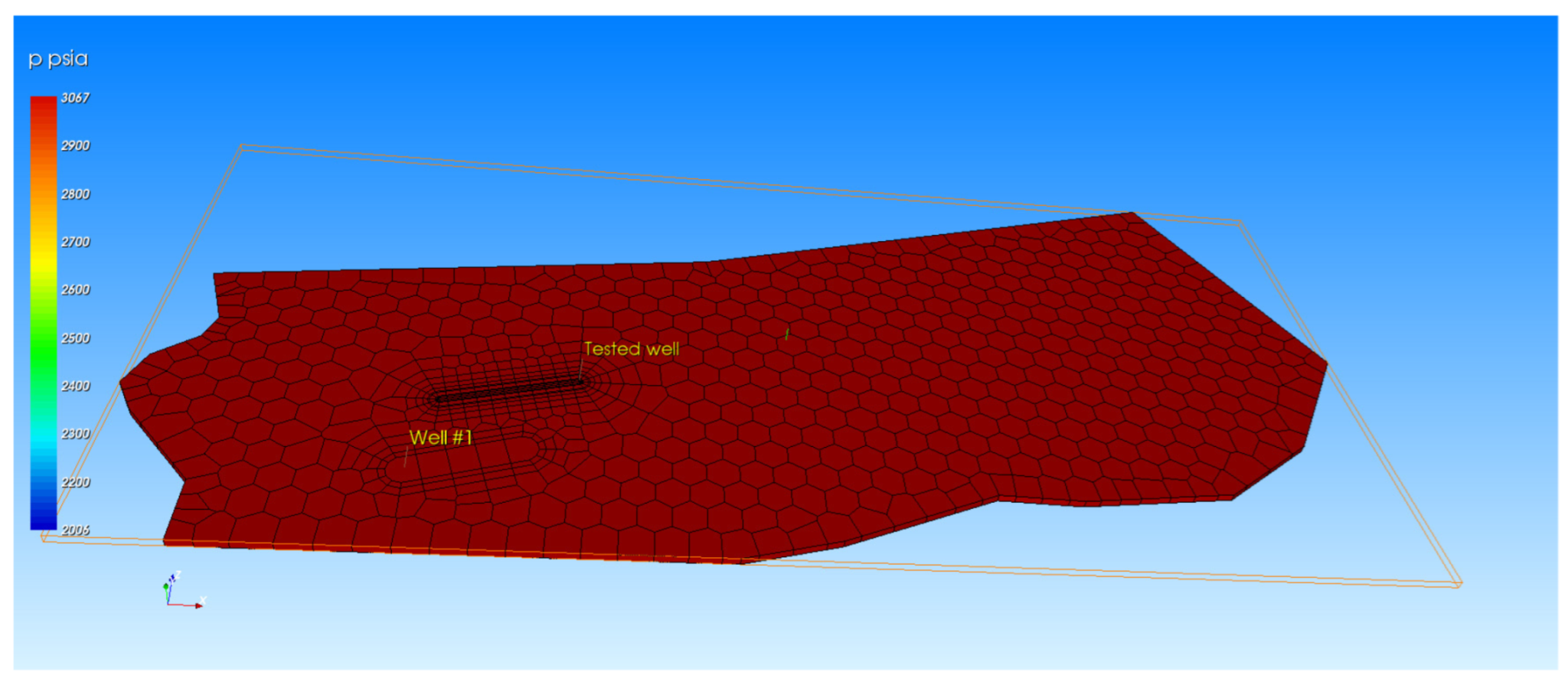
- Well trajectory:Well trajectory is mainly A-3; the average permeability of this layer is slightly lower. At the same time, the well trajectory slants through the formation as shown in Figure 10 or shows bending shape in the formation. The fluid flow direction in the formation intersects with the fluid flow direction in the production well or the injection well, which is inconsistent with the theoretical model, leading to the abnormality of the field well test curve.
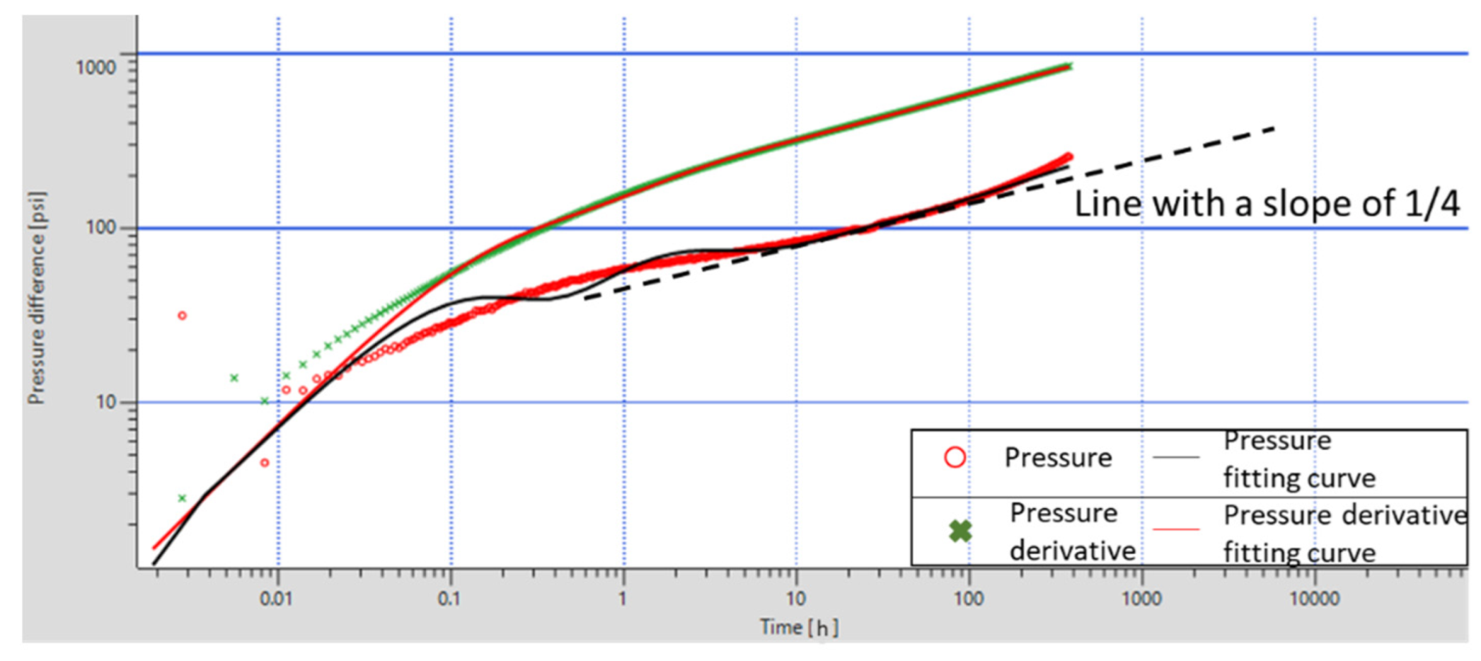
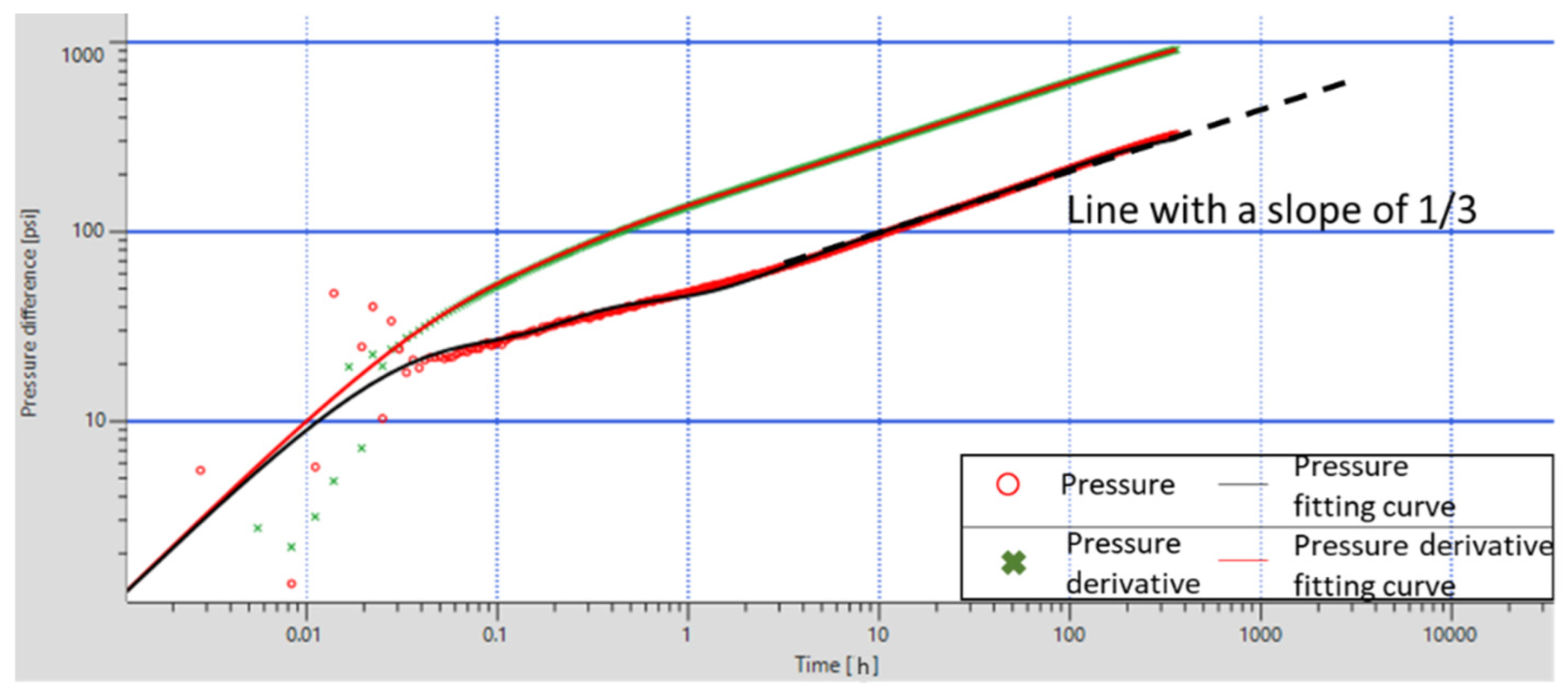
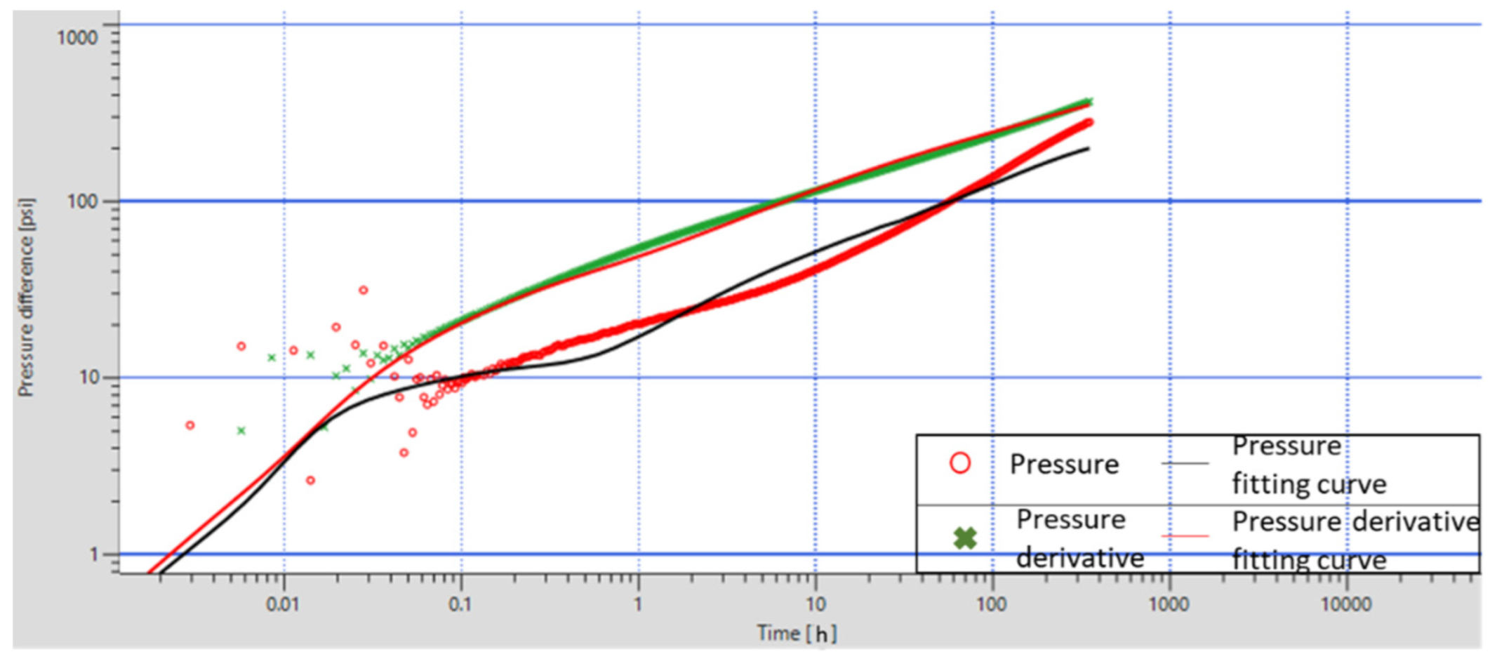
- Reservoir properties:Combined with geological understanding, reservoir properties around the well with bilinear flow are poor. Combined with a series of well test curves under different formation permeability conditions established by PTA in KAPPA, we can see that when the formation permeability is low, the slope of the linear flow section becomes lower, the linear flow occurs late, and does not reach the radial flow stage, as shown in Figure 11.
- Other factors:The possible influencing factors also include the transition between radial flow and stable linear flow and the existence of white spots. Due to well test time constraints, the transition between initial radial flow and 1/2 slope linear flow may not be observed. The main production layers of reservoir A developed discontinuous white spots, which hindered the fluid flow to a certain extent. However, due to its horizontal discontinuous distribution, its influence is limited.
5. Dynamic Analysis of Typical Horizontal Well Pattern
5.1. Well Test Result
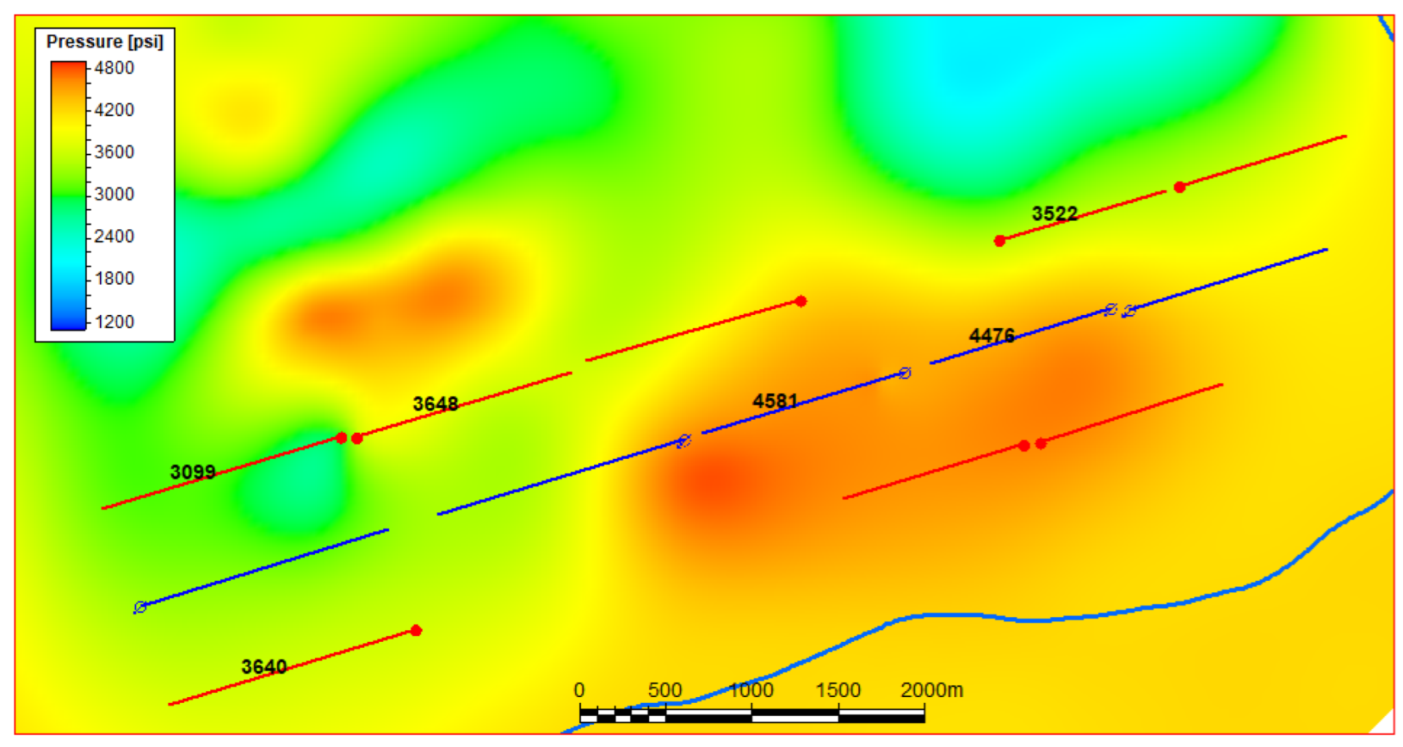
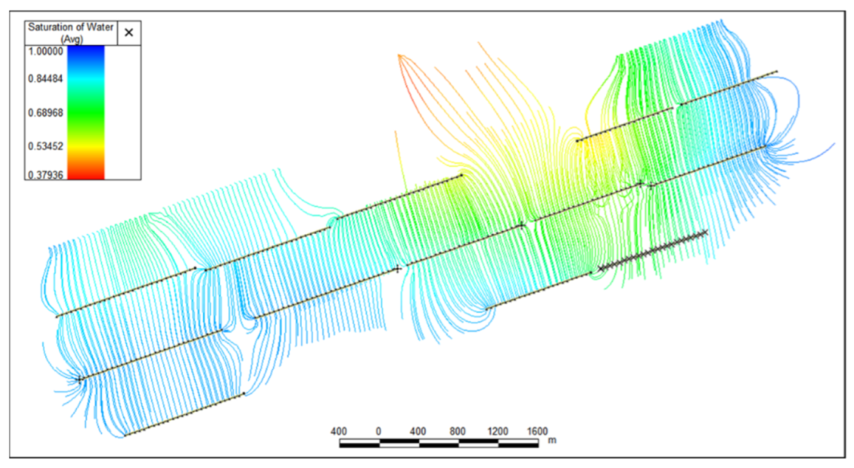
5.2. Reservoir Pressure
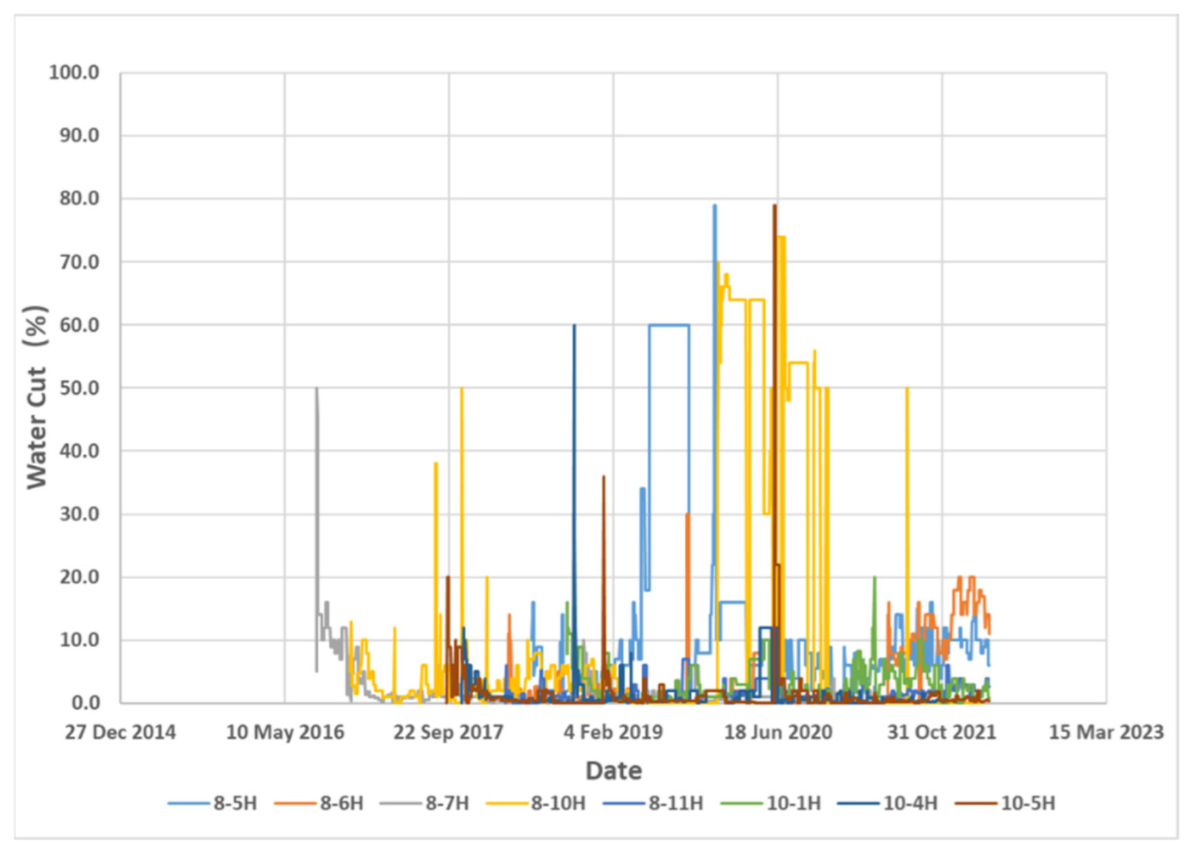
5.3. Well Water Cut
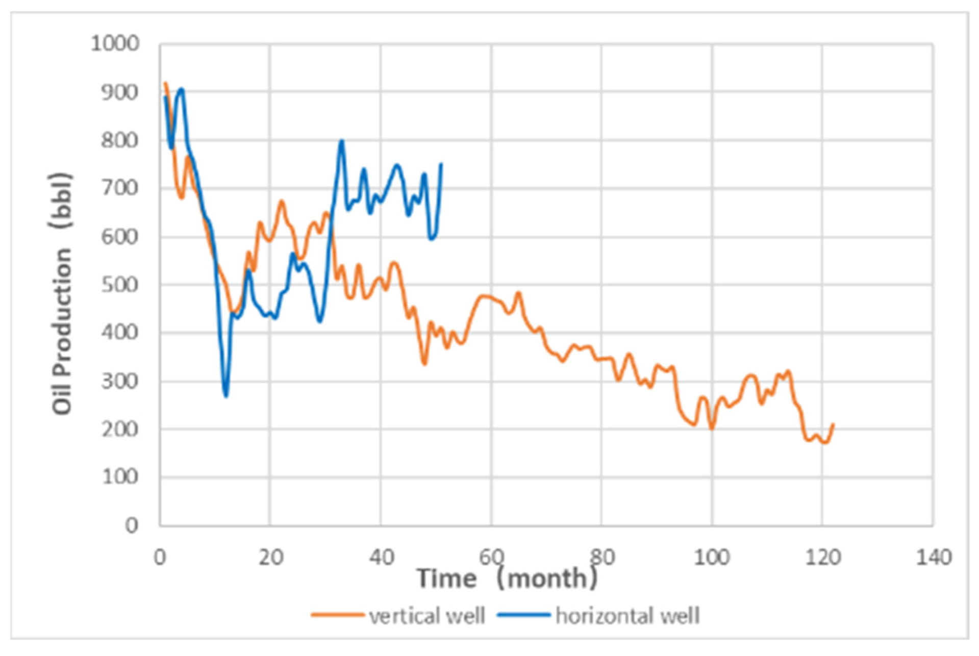
5.4. Well Production
6. Discussion
7. Conclusions
- The well test curves of low permeability carbonate reservoirs in the study area are generally characterized by no radial flow stage, changing wellbore storage effect and small openings of the double logarithmic curve.
- Most horizontal wells show a linear flow with a slope of 1/2, and there are also a few linear flow stages with a slope of 1/3 and a slope of 1/4. This anomalous feature is less affected by the difference in inter-layer permeability, and the influencing factors are well trajectory and reservoir properties. The transition between radial flow and stable linear flow and the existence of white spots also have certain effects on the characteristics of well test curves.
- Based on the above dynamic and static data and the analysis of well test interpretation results, it can be obtained that there is no pollution in the formation of the study area, and the development effect is overall good. However, there are still differences among various injection wells and production wells, and the main control factors are reservoir properties.
- Further injection-production optimization measures include:
- The injection parameters of 9-3H and 9-4H need to be adjusted to improve the pressure build-up condition.
- It is necessary to detect production parameters such as yield, water cut and pressure in time to prevent rapid increase of water cut and ensure stable production.
- The water injection volume of injection wells around reopened production wells should be adjusted according too a time frame designed to prevent flooding.
Author Contributions
Funding
Conflicts of Interest
References
- Roberts, D.G. Sedimentary Basins and Petroleum Geology of the Middle East. Mar. Pet. Geol. 1997, 16, 379. [Google Scholar] [CrossRef]
- Daviau, F.; Mouronval, G.; Bourdarot, G.; Curutchet, P. Pressure Analysis for Horizontal Wells. SPE Form. Eval. 1988, 3, 716–724. [Google Scholar] [CrossRef]
- Goode, P.A.; Thambynayagam, R. Pressure Drawdown and Buildup Analysis of Horizontal Wells in Anisotropic Media. SPE 1987, 2, 683–697. [Google Scholar] [CrossRef]
- Odeh, A.S.; Babu, D.K. Transient Flow Behavior of Horizontal Wells, Pressure Drawdown, and Buildup Analysis. SPE Form. Eval. 1990, 5, 7–15. [Google Scholar] [CrossRef]
- Spivey, J.P.; Lee, W.J. Estimating the Pressure-Transient Response for a Horizontal or a Hydraulically Fractured Well at an Arbitrary Orientation in an Anisotropic Reservoir. SPE Res. Eval. Eng. 1999, 2, 462–469. [Google Scholar] [CrossRef]
- Cinco-Ley, H.; Samaniego, V.F. Transient Pressure Analysis for Fractured Wells. J. Pet. Technol. 1981, 33, 1749–1766. [Google Scholar] [CrossRef]
- Du, K.; Stewart, G. Transient Pressure Response of Horizontal Wells in Layered and Naturally Fractured Reservoirs with Dual-Porosity. In Proceedings of the SPE Annual Technical Conference and Exhibition, Washington, DC, USA, 4–7 October 1992. [Google Scholar] [CrossRef]
- Briceno, M.; Summers, L.E.; Quijada, O.J. Horizontal Wells Pressure Build Up Analysis in Orinoco Heavy Oil Belt. In Proceedings of the SPE International Thermal Operations and Heavy Oil Symposium and International Horizontal Well Technology Conference, Calgary, AB, Canada, 4–7 November 2002. [Google Scholar] [CrossRef]
- Feng, W.C.; Nurafza, P.; Al-Shamma, B.; Gringarten, A. Bilinear Flow in Horizontal Wells in a Homogeneous Reservoir: Huntington Case Study. In Proceedings of the European Conference 2015, Madrid, Spain, 1–4 June 2015. [Google Scholar] [CrossRef]
- Baba, A.; Azzouguen, A.; Mazouzi, A.; Tiab, D.; Aissaoui, K. Determination of the Controlling Factors and Origins of the Bilinear Flow from Horizontal Well Transient Responses. In Proceedings of the Canadian International Petroleum Conference, Calgary, AB, Canada, 11–13 June 2002. [Google Scholar] [CrossRef]
- Yonglv, J.; Xuewen, Y.; Jianguo, G. Study on Variable Well Storage in Well Test Analysis. Xinjiang Pet. Geol. 1998, 19, 4. [Google Scholar]
- Shiqing, C.; Weirong, X.; Kangliang, G.; Jianlin, L. Typical Curve Characteristics and Case Analysis of Variable Wellbore Storage Effect. Well Test. 1992, 4, 9. [Google Scholar]
- Keyi, Z.; Lize, L.; Liping, J.; Kangliang, G.; Fei, L.; Haiping, H.; Xin, L. Pressure buildup curve behavior of pore type carbonate reservoir in AH Oilfield of Iraq. Fault-Block Oil Gas Field 2014, 21, 762–766. [Google Scholar] [CrossRef]
- Qishen, L.; Cheng, H.; Wei, D. A new well test model solution for fractured—Pore reservoir. J. Southwest Pet. Inst. 2002, 24, 71–73. [Google Scholar] [CrossRef]
- Jia, B.; Xian, C.-G. Permeability measurement of the fracture-matrix system with 3D embedded discrete fracture model. Pet. Sci. 2020. [Google Scholar] [CrossRef]
- Liu, Y.; Wu, X.; Wang, Y.; He, F.; Yuan, Y. Build a bridge between well testing theory and application. Well Test. 2006, 15, 5. [Google Scholar] [CrossRef]
- Enjie, H.; Lize, L.; Keyi, Z.; Xinmin, W.; Liping, J.; Zhaolei, S.; Kai, H. Water Production Characteristics and Control Measures of Porous Carbonate Reservoir in Iraq. J. Yangtze Univ. 2015, 12, 1–6. [Google Scholar] [CrossRef]
- Yong, L.; Qi, Z.; Chenji, W.; Benbiao, S. Dynamic Characterization of Different Reservoir Stacked Patterns for a Giant Carbonate Reservoir in Middle East. In Proceedings of the SPE Reservoir Characterisation and Simulation Conference and Exhibition, Abu Dhabi, United Arab Emirates, 5 May 2017. [Google Scholar] [CrossRef]
- Gringarten, A.C.; Ramey, H.J.J. The Use of Source and Green’s Functions in Solving Unsteady-Flow Problems in Reservoirs. Soc. Pet. Eng. J. 1973, 13, 285–296. [Google Scholar] [CrossRef]
- Xiangyan, K. Advanced Seepage Mechanics, 2nd ed.; University of Science and Technology of China Press: Hefei, China, 2010; pp. 203–233. [Google Scholar]
- Nengqiang, L. Practical Modern Well Test. Interpretation Method, 4th ed.; Petroleum Industry Press: Beijing, China, 2009; pp. 149–153. [Google Scholar]
- Xiaoping, L.; Liehui, Z.; Qiguo, L. Well Test. Analysis Method, 1st ed.; Petroleum Industry Press: Beijing, China, 2008; pp. 50–53. [Google Scholar]
- Suzuki, K.; Nanba, T. Horizontal Well Pressure Transient Behavior in Stratified Reservoirs. In Proceedings of the SPE Annual Technical Conference and Exhibition, Dallas, TX, USA, 6–9 October 1991. [Google Scholar] [CrossRef]
- Xiaoyun, L.; Yongqiang, W.; Chong, C.; Lianchao, J.; Lu, L. Theory and Application of Unstable Well Test Analysis for Horizontal Wells. Well Test. 2012, 21, 5–10. [Google Scholar]
- Liang, W.; Ruiting, B. Well Test Analysis and Application of Horizontal Well In Low Permeability Reservoir. West.-China Explor. Eng. 2010, 22, 44–47. [Google Scholar] [CrossRef]
- Xin, L.; Baozhen, J.; Zheng, C.; Yang, W.; Ting, Z. Application of Combination of Dynamic Analysis and Numerical Well Test In Solving Multi-solution Problem of Well Test. Neijiang Technol. 2014, 35, 3. [Google Scholar] [CrossRef]


| Liner Flow Stage Slope | 1/2 | 1/3 | 1/4 |
|---|---|---|---|
| Total | 8 | 2 | 2 |
| Proportion | 66.67% | 16.67% | 16.67% |
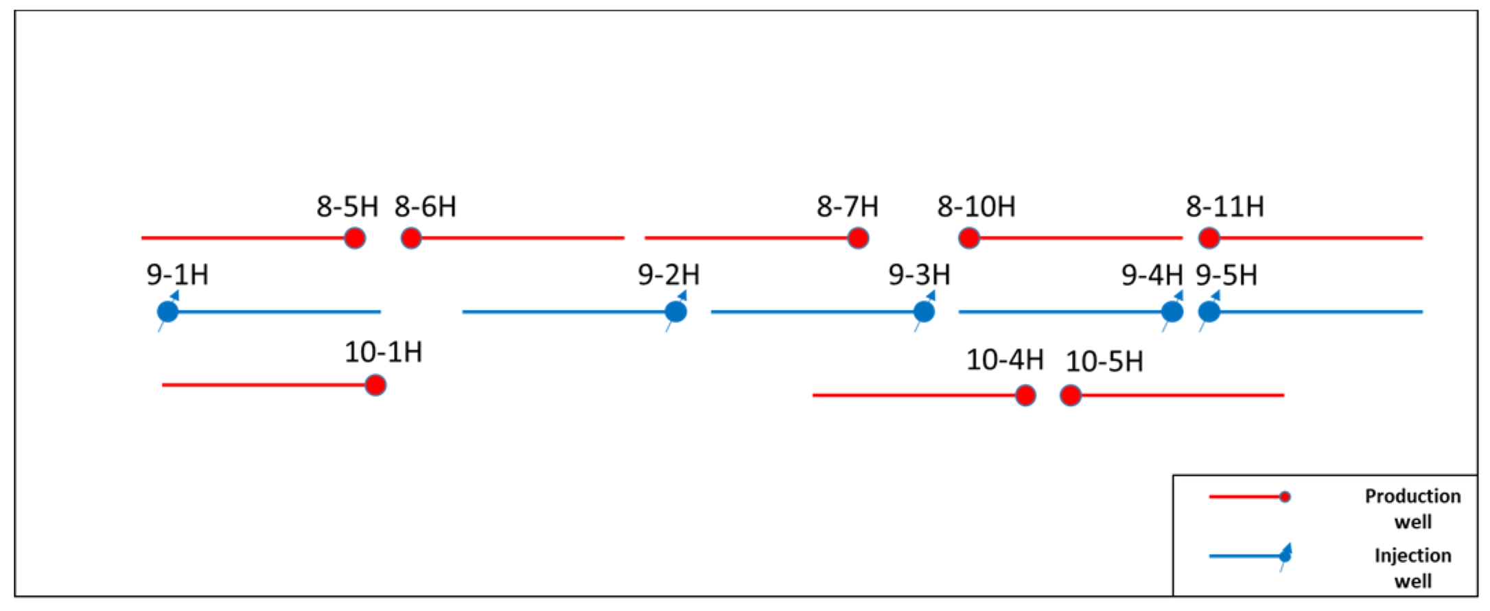
| Production Well | Corresponding Injection Well |
|---|---|
| 8-5H | 9-1H |
| 8-6H | 9-2H |
| 8-7H | 9-2H, 9-3H |
| 8-10H | 9-4H, 9-5H |
| 8-11H | 9-5H |
| 10-1H | 9-1H |
| 10-4H | 9-3H, 9-4H |
| 10-5H | 9-4H, 9-5H |
| Well | Time | Skin | Permeability (mD) | Effective Length (m) | Injectivity Index (bbl/d/psia) | Interpretation Model |
|---|---|---|---|---|---|---|
| 9-1H | August 2019 | −0.12 | 2.58 | 575 | −1.65 | Horizontal and Homogeneous |
| June 2020 | 0.00 | 4.06 | 518 | −1.97 | Horizontal and Homogeneous | |
| 9-2H | January 2019 | −0.08 | 4.66 | 616 | −3.06 | Horizontal and Radial Composite |
| May 2020 | −0.13 | 3.43 | 591 | −1.92 | Horizontal and Radial Composite | |
| 9-3H | June 2019 | −0.14 | 4.65 | 628 | −2.29 | Horizontal and Homogeneous |
| January 2020 | −0.12 | 3.41 | 656 | −1.90 | Horizontal and Homogeneous | |
| 9-4H | April 2019 | −0.16 | 4.32 | 520 | −2.22 | Horizontal and Homogeneous |
| February 2020 | −0.11 | 2.47 | 811 | −1.84 | Horizontal and Homogeneous | |
| 9-5H | April 2020 | −0.17 | 2.80 | 610 | −1.63 | Horizontal and Homogeneous |
| Well | Time | Skin | Permeability (mD) | Effective Length (m) | Production Index (bbl/d/psia) | Interpretation Model |
|---|---|---|---|---|---|---|
| 8-5H | December 2020 | −6.96 | 2.31 | 317 | 0.80 | Horizontal and Homogeneous |
| 10-1H | December 2022 | −7.30 | 7.29 | 513 | 1.22 | Horizontal and Homogeneous |
Publisher’s Note: MDPI stays neutral with regard to jurisdictional claims in published maps and institutional affiliations. |
© 2022 by the authors. Licensee MDPI, Basel, Switzerland. This article is an open access article distributed under the terms and conditions of the Creative Commons Attribution (CC BY) license (https://creativecommons.org/licenses/by/4.0/).
Share and Cite
Zhao, Z.; Li, Y.; Jiang, T.; Hu, D.; Zhang, L.; Ma, R. Analysis and Application of Horizontal Well Test in Low Permeability Porous Carbonate Reservoir. Processes 2022, 10, 1545. https://doi.org/10.3390/pr10081545
Zhao Z, Li Y, Jiang T, Hu D, Zhang L, Ma R. Analysis and Application of Horizontal Well Test in Low Permeability Porous Carbonate Reservoir. Processes. 2022; 10(8):1545. https://doi.org/10.3390/pr10081545
Chicago/Turabian StyleZhao, Zeqi, Yong Li, Tongwen Jiang, Dandan Hu, Lixia Zhang, and Ruicheng Ma. 2022. "Analysis and Application of Horizontal Well Test in Low Permeability Porous Carbonate Reservoir" Processes 10, no. 8: 1545. https://doi.org/10.3390/pr10081545