
Geometric Calculation of the Influence of an Oscillating Sieve’s Actuation Mechanism Position on Its Motion


Abstract
:
1. Introduction
- (1)
- Mechanical separators—which perform the separation of heterogeneous mixtures of solid particles;
- (2)
- Oscillating transport—transporting a mixture of solid particles by jumps.
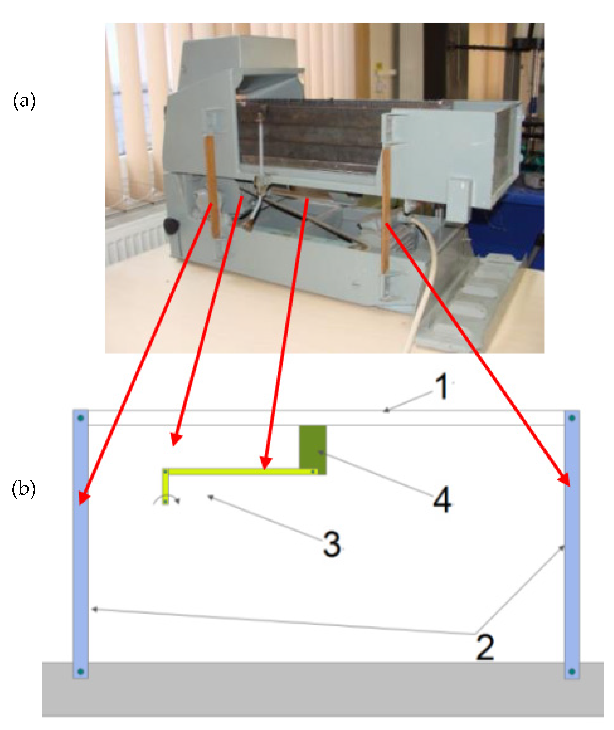
2. Equipment
- ①
- A sieve;
- ②
- The tyrants;
- ③
- Sieve drive mechanism—crank mechanism;
- ④
- A fastening element of the crank mechanism on the sieve.
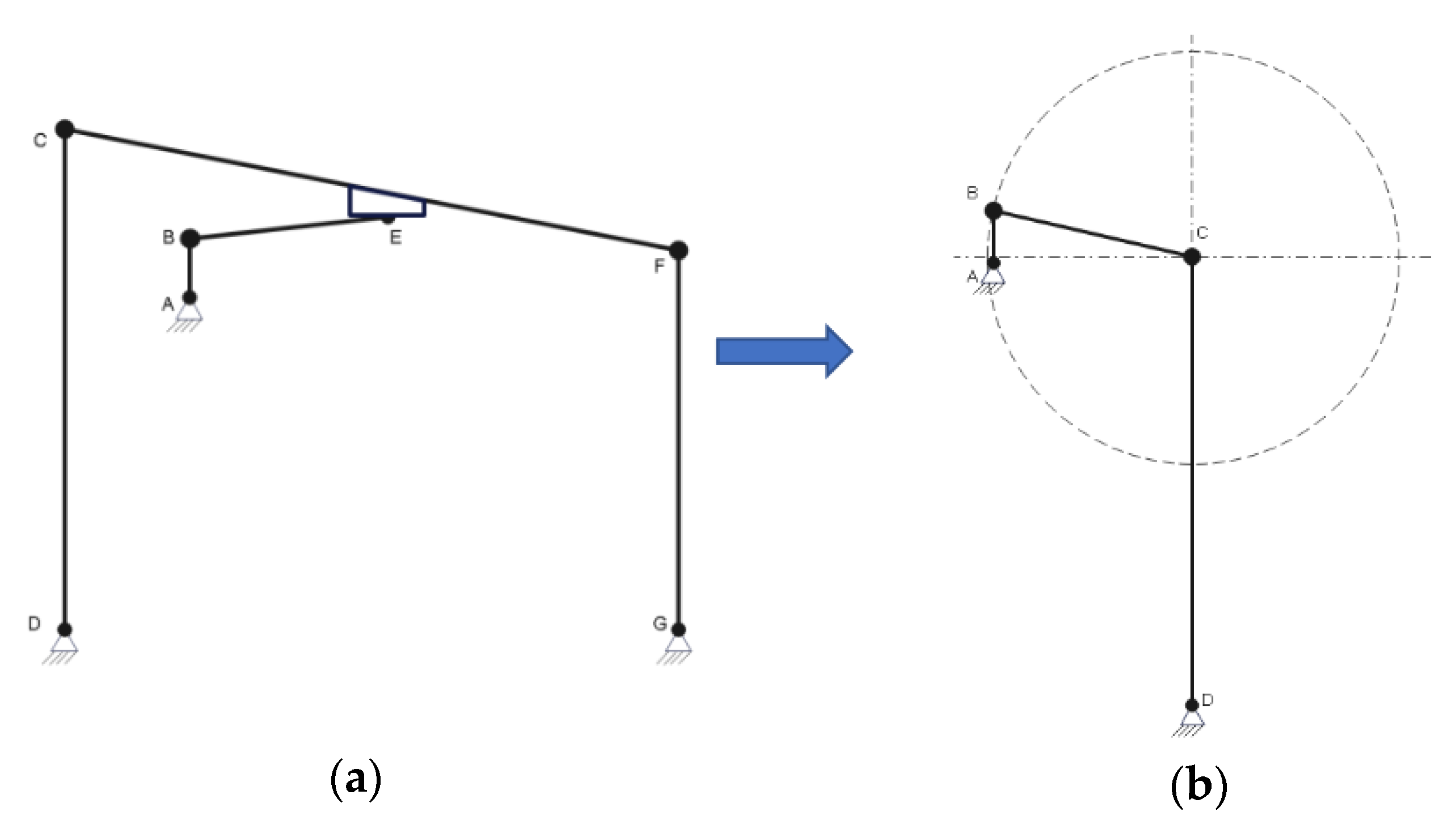
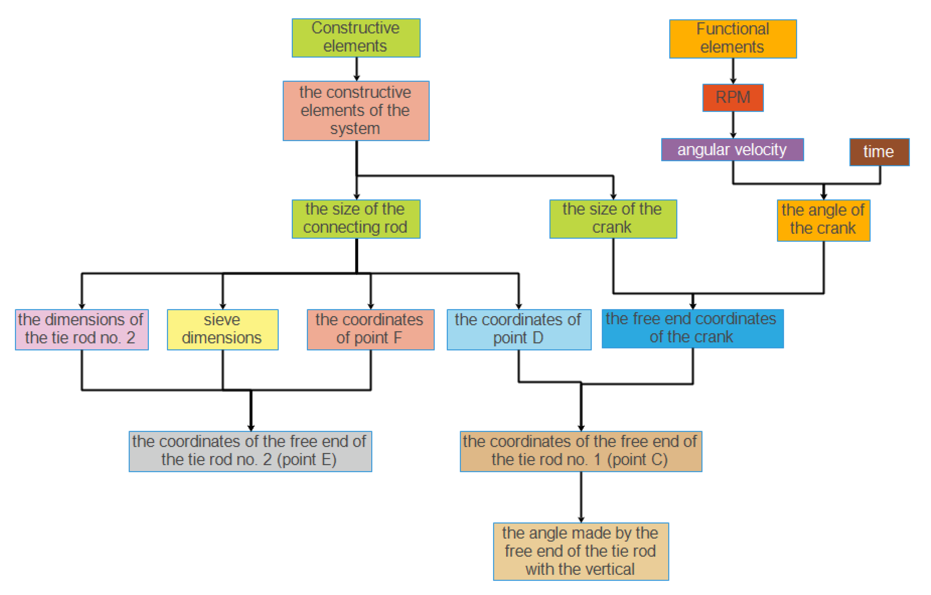
3. Geometric Construction of a Dynamic Mechanism
- ○
- Lengths:
- The crank (AB) has the size a;
- Connecting rod (BC) has the size b;
- Tie rod no. 1 (CD) has the size c;
- Tie rod no. 2 (EF) has the size e;
- The sieve (CE) has the size d.
- ○
- Angles:
- The angle of inclination of the crank about the horizontal α;
- The inclination angle of the connecting rod with the horizontal β;
- The inclination angle of the tie rod no. 1 with the horizontal φ;
- The inclination angle of the tie rod no. 2 with the horizontal θ1;
- The angle of inclination of the sieve with the horizontal θ0.
- −
- The correlation between the angular velocity and the angle described by the crank about the horizontal was identified. For this, the connection was made between the value of the angular velocity, the angle described by the crank, and the time necessary to achieve a complete rotation [3].
- −
- The reference time from which the analysis starts, i.e., t1 = 0.000001 s;
- −
- The time required to make a complete rotation (360°):
- −
- A time variation interval was created using the calculation relation:
- −
- The coordinates for the fixed point F (respectively xF and yF—the element representing the fixed end of the tie rod) can be determined using equations:
- −
- Since the aim was to obtain a general relationship, it must be taken into account that in some situations the correlations between terms may change (from + to −).
4. Methodology
- −
- Tie rod no. 1, c = 0.587 m;
- −
- Crank, a = 0.065 m;
- −
- Connecting rod, b = 0.27 m;
- −
- Sieve length, d = 1 m;
- −
- Rpm of the rod-crank mechanism, nAB = 100 rot/min;
- −
- Coordinates of point A are x0, y0 = 0, 0;
- −
- Tie rod no. 2, e = 0.587 m.
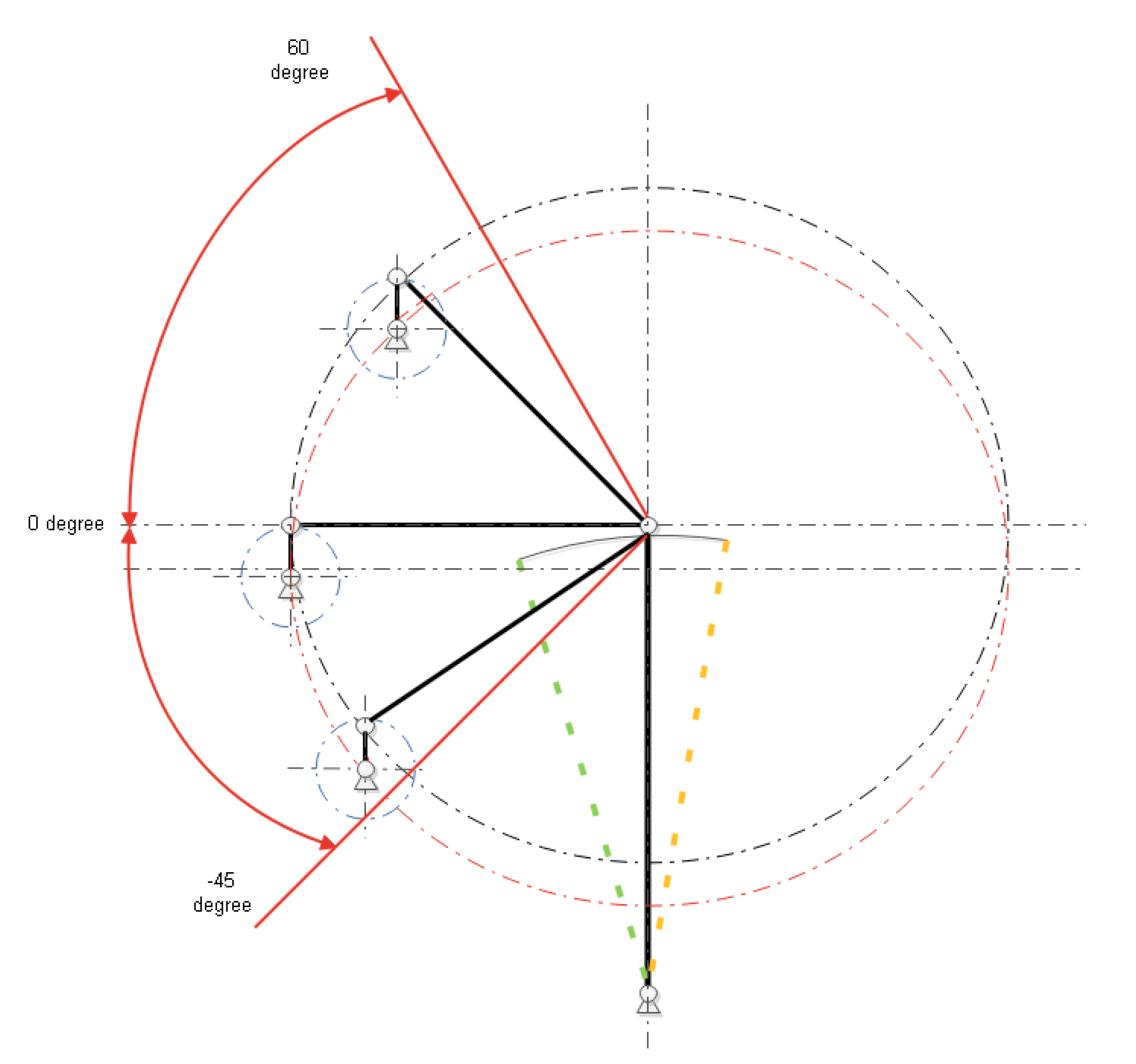
5. Results
- o
- Positive values correspond to the position on the left side of the vertical;
- o
- Negative values correspond to the position on the right side of the vertical.
- The position of the driving device had a direct impact on the form of the variation in the speed of movement of the tie rod’s free end;
- The largest difference between the maximum and minimum value of the studied parameter was recorded for an angle of 45 degrees and corresponded to 3.082 m/s;
- The smallest difference between the maximum and minimum value of the studied parameter was recorded for an angle of −15 degrees and corresponded to 0.69 m/s;
- Regardless of the position of the driver, it was found that there are two points with a value of 0, corresponding to the change in the direction of travel of the free end of the tie rod;
- In order to identify the behavior of a solid particle on the surface of the screen subjected to an oscillatory motion, an analysis must be carried out, combining information about the motion of the free end of the tie rod and its velocity;
- In the case of positioning the drive device at an angle value of 45 degrees, as compared to other positions, there is a sudden increase in the value of the displacement speed of the free end of the tie rod after a period of an approximately constant value;
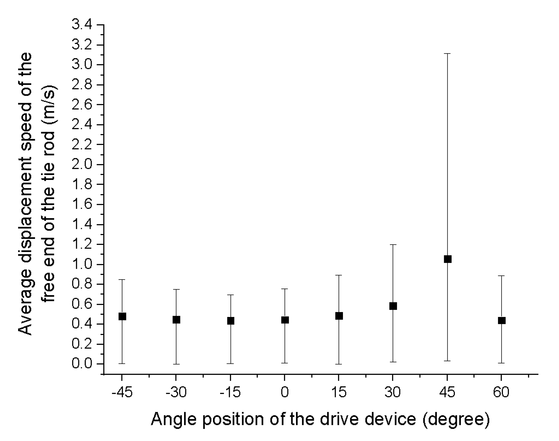
- Analyzing the average value of the free end displacement speed of the tie rod (Figure 11), it was identified that the highest value corresponded to the position of 45 degrees and the lowest to the position of −15 degrees.
- −
- The highest value of the parameter presented was obtained for a β angle of 45 degrees and corresponded to 1.05 m/s;
- −
- The lowest value of the presented parameter was obtained for a β angle of −15 degrees and corresponded to 0.43 m/s;
- −
- By analyzing the corresponding error representations, the lowest value was 0.00136 m/s (for a β angle of 15 degrees) and the highest is 3.115 m/s (for a β angle of 45 degrees).
- −
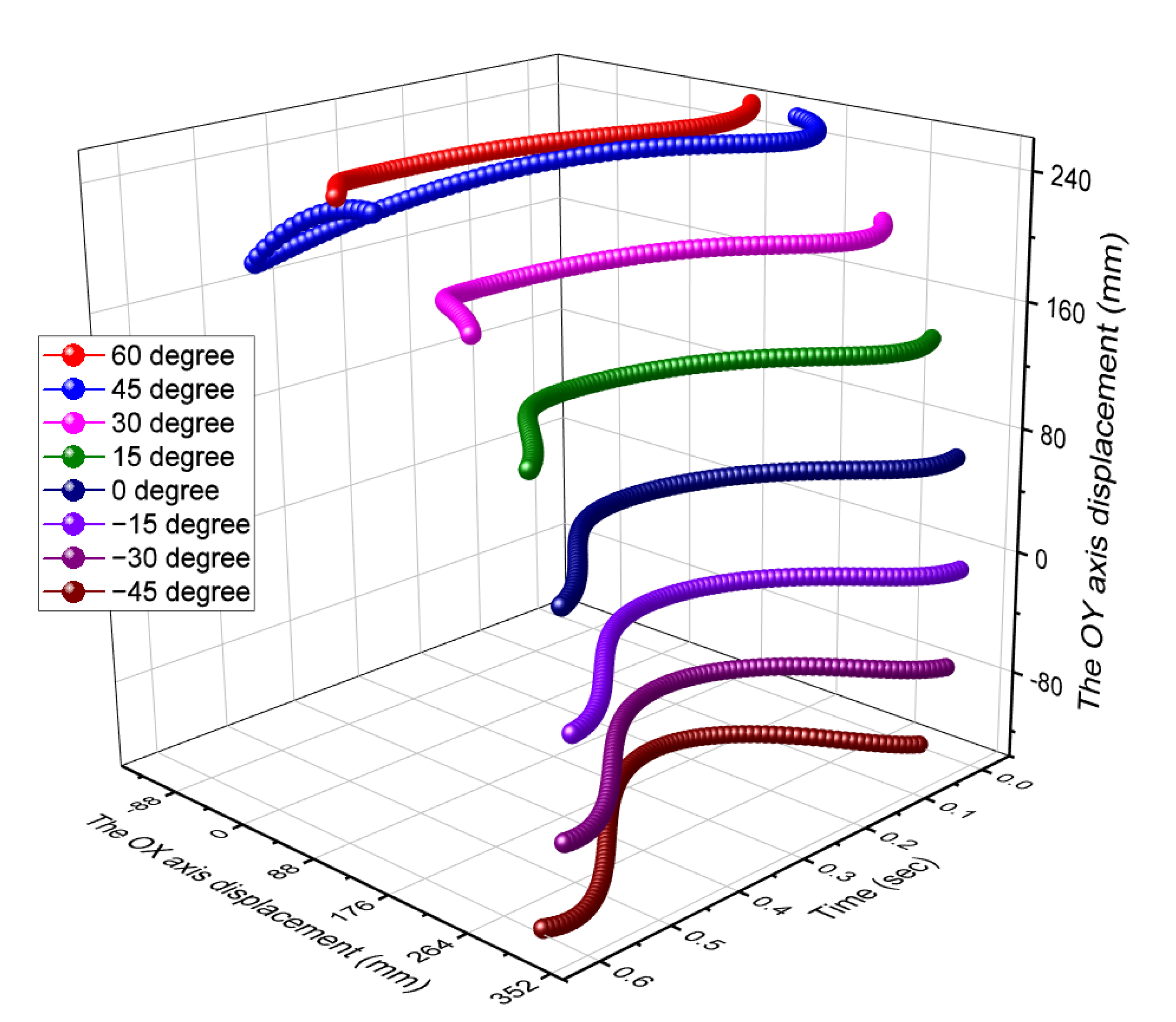
- The trajectories obtained from the mathematical analysis (Figure 7) coincide with those found in the literature;
- −
- Compared to the literature, the article presents how to determine the position of the studied mechanism components. These mathematical relations have a general computational character, respecting the specific constructive requirements of this mechanism;
- −
- The calculation relations identified (relations (9), (10), and (14)) have not been found in the literature, therefore, the present article is distinguished from the existing ones by these;
- −
- No studies have been identified in the literature aimed at identifying the influence of the position of the drive device (connecting rod-crank) on the movement of an oscillating screen.
6. Conclusions
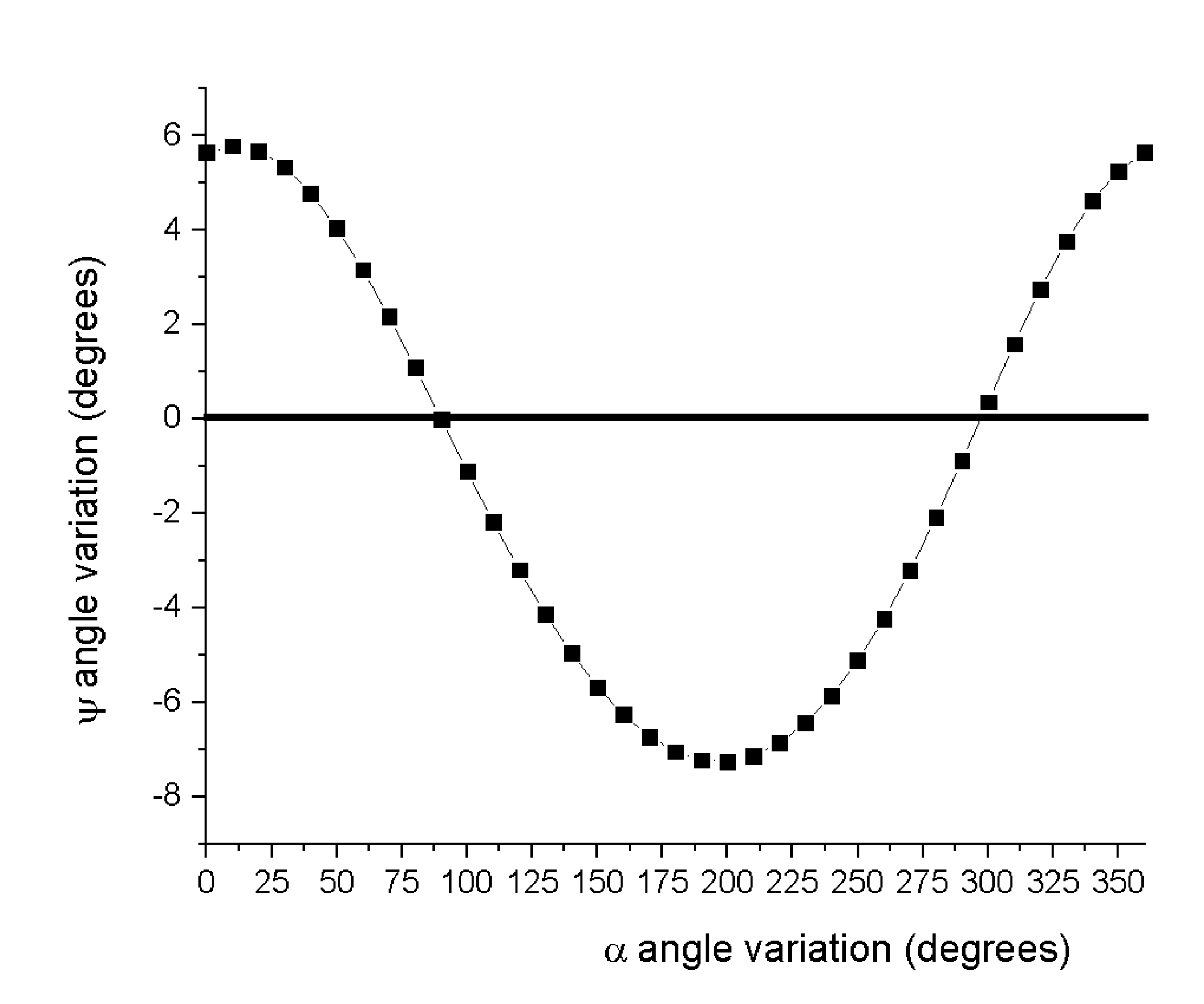
- −
- For a maximum value of β = 60°, the free end of the tie rod moved predominantly to the left side;
- −
- For a minimum value of β = −45°, the free end of the tie rod moved predominantly to the right side;
- −
- For the value of the angle β = 0°, the movement executed by the titan was symmetrical concerning the vertical.
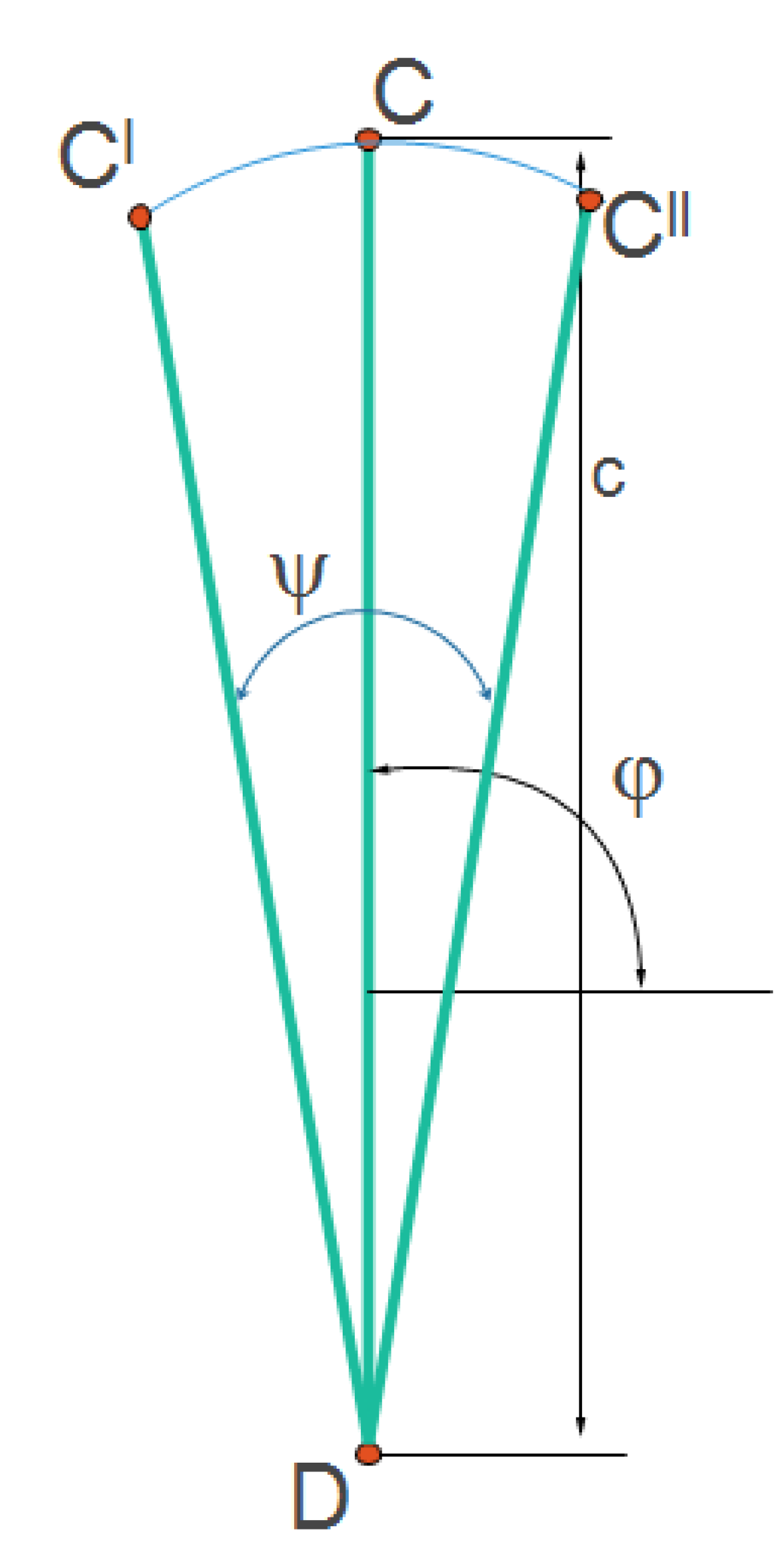
- −
- The smallest value of the angle ψ = 12.7° was obtained for a β angle of 30°.
- −
- The smallest value of the angle ψ = 31.45° was obtained for a β angle of −45°.
- −
- It is also found that the speed of movement of the free end of the tie rod was influenced by the position of the sieve drive mechanism, respectively. By analyzing the variation of the displacement speed of the free end of the tie rod, according to Figure 10, it can be stated that:
- o
- For β angle values between 0 and −45 degrees, an approximate sinusoidal graphical representation was obtained, and for the other values of the reference angle, an irregular speed variation was obtained;
- o
- The smallest value of the represented parameter, 0.00136 m/s, was obtained for the β angle of 15 degrees at a time of 0.036 s;
- o
- The highest value of the represented parameter, 3.115 m/s, was obtained for the β angle of 45 degrees at a time of 0.522 s.
- −
- Following the analysis of the graphical representation of the average displacement speed of the free end of the tie rod (Figure 11), it was concluded that:
- o
- The highest value of the average displacement velocity of the free end of the tie rod was obtained for a β angle of 45 degrees corresponding to 1.05 m/s. This value was obtained due to the large difference between the minimum and maximum values of the studied parameter;
- o
- The minimum value of the average displacement velocity of the free end of the tie rod was obtained for a β angle of −15 degrees corresponding to 0.438 m/s. This value was also closely related to the mode of speed variation, as shown in the graph in Figure 10.
Author Contributions
Funding
Institutional Review Board Statement
Informed Consent Statement
Data Availability Statement
Conflicts of Interest
References
- Bontas, O.; Nedeff, V.; Mosnegutu, E.F.; Panainte, M.; Irimia, O.T. Behaviour of solid particles on a flat oscillating surface. Environ. Eng. Manag. J. 2013, 12, 17–22. [Google Scholar] [CrossRef]
- Mosnegutu, E.; Nedeff, V.; Panainte, M. Comparative study between particles separation on sieve and on air current. MOCM 2003, 1, 59–64. [Google Scholar]
- Grandison, A.S.; Lewis, M.J. Separation Process in the Food and Biotechnology Industries, Principles and Aplication; Woodhead Publishing Limited: Cambridge, UK, 1996. [Google Scholar]
- Ahmedalbashir, M.; Romdhane, L.; Lee, J. Dynamics of a four-bar mechanism with clearance and springs—Modeling and experimental analysis. J. Mech. Sci. Technol. 2017, 31, 1023–1033. [Google Scholar] [CrossRef]
- Akhadkar, C.A.; Deoghare, A.B.; Vaidya, A.M. Simulation and experimental response of four-bar mechanism with tolerance stack. J. Mech. Eng. Sci. 2019, 13, 4512–4535. [Google Scholar] [CrossRef]
- Akhadkar, N.; Acary, V.; Brogliato, B. Analysis of collocated feedback controllers for four-bar planar mechanisms with joint clearances. Multibody Syst. Dyn. 2016, 38, 101–136. [Google Scholar] [CrossRef]
- Al-Smadi, Y.M.; Russell, K.; Sodhi, R.S. Planar four-bar path generation with static structural conditions. J. Adv. Mech. Des. Syst. Manuf. 2008, 2, 926–936. [Google Scholar] [CrossRef]
- Boskovic, M.; Bulatovic, R.R.; Salinic, S.; Miodragovic, G.R.; Bogdanovic, G.M. Optimization of dynamic quantities of a four-bar mechanism using the hybrid cuckoo search and firefly algorithm (H-CS-FA). Arch. Appl. Mech. 2018, 88, 2317–2338. [Google Scholar] [CrossRef]
- Attia, E.M.; Abd El-Naeem, M.A.; El-Gamal, H.A.; Awad, T.H.; Mohamed, K.T. Simulation of the motion of a four bar prosthetic knee mechanism fitted with a magneto-rheological damper. J. Vibroengineering 2016, 18, 4051–4068. [Google Scholar] [CrossRef]
- Arman, R.; Mahyuddin, A.I.; Marthiana, W.; Satria, I. Experimental investigation of vibration response of a flexible coupler in a four bar mechanism due to varying crank length and crank speed. In Proceedings of the 4th Engineering Science and Technology International Conference (Estic 2018), Padang, Indonesia, 28–29 August 2018; Volume 248. [Google Scholar]
- Buskiewicz, J. Reduced number of design parameters in optimum path synthesis with timing of four-bar linkage. J. Theor. Appl. Mech. 2018, 56, 43–55. [Google Scholar] [CrossRef]
- Chou, Y.S.; Liu, J.S. A robotic indoor 3D mapping system using a 2D Laser range finder mounted on a rotating four-bar linkage of a mobile platform. Int. J. Adv. Robot. Syst. 2013, 10, 45. [Google Scholar] [CrossRef]
- Jamniczky, H.A.; Harper, E.E.; Garner, R.; Cresko, W.A.; Wainwright, P.C.; Hallgrimsson, B.; Kimmel, C.B. Association between integration structure and functional evolution in the opercular four-bar apparatus of the threespine stickleback, Gasterosteus aculeatus (Pisces: Gasterosteidae). Biol. J. Linn. Soc. 2014, 111, 375–390. [Google Scholar] [CrossRef] [Green Version]
- D’Alessio, J.; Russell, K.; Sodhi, R.S. Spherical four-bar motion generation and axode generation in cam mechanism design. J. Adv. Mech. Des. Syst. Manuf. 2016, 10, JAMDSM0028. [Google Scholar] [CrossRef]
- Jin, S.; Kim, J.; Bae, J.; Seo, T.; Kim, J. Design, modeling and optimization of an underwater manipulator with four-bar mechanism and compliant linkage. J. Mech. Sci. Technol. 2016, 30, 4337–4343. [Google Scholar] [CrossRef]
- Lee, S.; Kim, J.W.; Seo, T.; Kim, J. Four-bar linkage-based automatic tool changer: Dynamic modeling and torque optimization. J. Mech. Sci. Technol. 2017, 31, 2407–2413. [Google Scholar] [CrossRef]
- Li, S.L.; Hang, L.B.; Wang, M.Y.; Bai, L.L.; Huang, X.B.; Deng, H.Y.; Liu, Z.; Chen, Y.; Hua, Y.; Du, J.L. Research on four-bar linkage with variable axis torsion spring for vehicle latch lock/unlock. In Proceedings of the 2019 International Conference on Robotics, Intelligent Control and Artificial Intelligence (Ricai 2019), Shanghai, China, 20–22 September 2019; pp. 153–158. [Google Scholar]
- Yu, S.; Li, T.; Ji, F.; Zhao, S.; Liu, K.; Zhang, Z.; Zhang, W.; Mei, Y. Trimer-like microrobots with multimodal locomotion and reconfigurable capabilities. Mater. Today Adv. 2022, 14, 100231. [Google Scholar] [CrossRef]
- Li, T.; Zhang, A.; Shao, G.; Wei, M.; Guo, B.; Zhang, G.; Li, L.; Wang, W. Janus microspheres: Janus microdimer surface walkers propelled by oscillating magnetic fields. Adv. Funct. Mater. 2018, 28, 1870173. [Google Scholar] [CrossRef]
- Ji, F.; Li, T.; Yu, S.; Wu, Z.; Zhang, L. Propulsion Gait Analysis and Fluidic Trapping of Swinging Flexible Nanomotors. ACS Nano 2021, 15, 5118–5128. [Google Scholar] [CrossRef]
- Wang, H.; Yu, S.; Liao, J.; Qing, X.; Sun, D.; Ji, F.; Song, W.; Wang, L.; Li, T. A robot platform for highly efficient pollutant purification. Front. Bioeng. Biotechnol. 2022, 10, 903219. [Google Scholar] [CrossRef]
- Soong, R.C. A design method for four-bar mechanisms with variable speeds and length-adjustable driving links. J. Adv. Mech. Des. Syst. Manuf. 2009, 3, 312–323. [Google Scholar] [CrossRef]
- Eqra, N.; Abiri, A.H.; Vatankhah, R. Optimal synthesis of a four-bar linkage for path generation using adaptive PSO. J. Braz. Soc. Mech. Sci. Eng. 2018, 40, 469. [Google Scholar] [CrossRef]
- Botta, F.; Verotti, M.; Bagolini, A.; Bellutti, P.; Belfiore, N.P. Mechanical response of four-bar linkage microgrippers with bidirectional electrostatic actuation. Actuators 2018, 7, 78. [Google Scholar] [CrossRef] [Green Version]
- Tanik, E.; Parlaktas, V. Fully compliant spatial four-bar mechanism. J. Adv. Mech. Des. Syst. Manuf. 2015, 9, JAMDSM0002. [Google Scholar] [CrossRef]
- Russell, K.; Shen, J. Planar four-bar motion and path generation with order and branching conditions. J. Adv. Mech. Des. Syst. Manuf. 2011, 5, 264–273. [Google Scholar] [CrossRef]
- Grubich, J.R.; Westneat, M.W. Four-bar linkage modelling in teleost pharyngeal jaws: Computer simulations of bite kinetics. J. Anat. 2006, 209, 79–92. [Google Scholar] [CrossRef]
- Romaniak, K.; Nessel, M. Coupler curves of four-bar linkages plotted in graphical programs. Arch. Mech. Eng. 2019, 66, 315–328. [Google Scholar]
- Salah, M.; Al-Jarrah, A.; Tatlicioglu, E.; Banihani, S. Robust backstepping control for a four-bar linkage mechanism driven by a DC motor. J. Intell. Robot. Syst. 2019, 94, 327–338. [Google Scholar] [CrossRef]
- Yin, L.R.; Han, J.Y.; Mao, C.; Huang, J.; Yang, T. Synthesis method based on solution regions for planar four-bar straight-line linkages. J. Mech. Sci. Technol. 2012, 26, 3159–3167. [Google Scholar]
- Rong, B.; Rui, X.T.; Tao, L. Dynamics and genetic fuzzy neural network vibration control design of a smart flexible four-bar linkage mechanism. Multibody Syst. Dyn. 2012, 28, 291–311. [Google Scholar] [CrossRef]
- Wang, Y.X. Dynamics of an elastic four bar linkage mechanism with geometric nonlinearities. Nonlinear Dyn. 1997, 14, 357–375. [Google Scholar] [CrossRef]
- Diab, N. A new graphical technique for acceleration analysis of four bar mechanisms using the instantaneous center of zero acceleration. Sn Appl. Sci. 2021, 3, 327. [Google Scholar] [CrossRef]
- Daniali, H.M.; Varedi, S.M.; Dardel, M.; Fathi, A. A novel algorithm for kinematic and dynamic optimal synthesis of planar four-bar mechanisms with joint clearance. J. Mech. Sci. Technol. 2015, 29, 2059–2065. [Google Scholar] [CrossRef]
- Wang, B.; Du, X.C.; Ding, J.Z.; Dong, Y.; Wang, C.J.; Liu, X.A. The synthesis of planar four-bar linkage for mixed motion and function generation. Sensors 2021, 21, 3504. [Google Scholar] [CrossRef] [PubMed]
- Romero, N.N.; Campos, A.; Martins, D.; Vieira, R.S. A new approach for the optimal synthesis of four-bar path generator linkages. Sn Appl. Sci. 2019, 1, 1504. [Google Scholar] [CrossRef] [Green Version]
- Valencia-Segura, L.E.; Villarreal-Cervantes, M.G.; Corona-Ramirez, L.G.; Cuenca-Jimenez, F.; Castro-Medina, R. Optimum synthesis of four-bar mechanism by using relative angle method: A comparative performance study. IEEE Access 2021, 9, 132990–133010. [Google Scholar] [CrossRef]
- Zhang, Z.Q.; Yang, Q.; Zhao, J.; Gui, S. Dynamic model and performance analysis of rigid-flexible coupling four-bar leg mechanism for small scale bio-inspired jumping robot. Microsyst. Technol.-Micro-Nanosyst.-Inf. Storage Processing Syst. 2019, 25, 3269–3285. [Google Scholar] [CrossRef]
- Cakar, O.; Tanyildizi, A.K. Application of moving sliding mode control for a DC motor driven four-bar mechanism. Adv. Mech. Eng. 2018, 10, 1–13. [Google Scholar] [CrossRef]
- Pickard, J.K.; Carretero, J.A.; Merlet, J.P. Towards the appropriate synthesis of the four-bar linkage. Trans. Can. Soc. Mech. Eng. 2018, 42, 1–9. [Google Scholar] [CrossRef]
- Martini, A.; Troncossi, M.; Carricato, M.; Rivola, A. Elastodynamic behavior of balanced closed-loop mechanisms: Numerical analysis of a four-bar linkage. Meccanica 2014, 49, 601–614. [Google Scholar] [CrossRef]
- Shariati, M.; Norouzi, M. Optimal synthesis of function generator of four-bar linkages based on distribution of precision points. Meccanica 2011, 46, 1007–1021. [Google Scholar] [CrossRef]
- Wu, R.; Li, R.Q.; Liang, H.L.; Ning, F.P. Mixed synthesis method of motion and path of planar four-bar linkages. Mech. Sci. 2021, 12, 443–449. [Google Scholar] [CrossRef]
- Yildiz, A.; Kopmaz, O.; Cetin, S.T. Dynamic modeling and analysis of a four-bar mechanism coupled with a CVT for obtaining variable input speeds. J. Mech. Sci. Technol. 2015, 29, 1001–1006. [Google Scholar] [CrossRef]
- Nassar, F.; Birglen, L. Force analysis of minimal self-adaptive fingers using variations of four-bar linkages. Mech. Sci. 2021, 12, 1037–1049. [Google Scholar] [CrossRef]
- Bontas, O. Possibilities to Optimise the Cleaning and Sorting Process of Agricultural Crop Products by Grain Width and Thickness. Ph.D. Thesis, “Vasile Alecsandri” University of Bacău, Bacău, Romania, 2013. [Google Scholar]
- Nedeff, V.; Moşneguţu, E.; Baisan, I. Mechanical Separation of Granular and Powdery Products in the Food Industry; TEHNICA-INFO: Chişinău, Moldova, 2001. [Google Scholar]
- Moşneguţu, E.; Nedeff, V.; Bontaş, O.; Bârsan, N.; Chiţimuş, A.D. Possibilities to determining the solid particle trajectories on an oscillating separation screen. J. Eng. Stud. Res. 2014, 20, 63–70. [Google Scholar]
- Peng, L.; Feng, H.; Wang, Z.; Wang, H.; Yang, H.; Huang, H. Screening mechanism and properties of a cantilevered vibrating sieve for particles processing. Appl. Sci. 2019, 9, 4911. [Google Scholar] [CrossRef] [Green Version]
- Natesan Arun, K. Kinematic Analysis and Synthesis of Four-Bar Mechanisms for Straight Line Coupler Curves. Ph.D. Thesis, Rochester Institute of Technology, Rochester, NY, USA, 1994. [Google Scholar]
- Sharifgalieva, I. The Design and Simulation of Mechanisms. Ph.D. Thesis, Arcada University of Applied Sciences, Helsinki, Finland, 2018. [Google Scholar]
- Goessner, S. Crank-Rocker—Design and Analysis. Available online: https://github.com/goessner/crocker#readme (accessed on 12 January 2021).
- Mathcad. Available online: https://www.mathcad.com/en (accessed on 27 July 2022).
- Yan, H.S.; Soong, R.C. An integrated design approach of four-bar linkages with variable input speed. JSME Int. J. Ser. C-Mech. Syst. Mach. Elem. Manuf. 2014, 47, 350–362. [Google Scholar] [CrossRef]
- Ahmadi, B.; Nariman-zadeh, N.; Jamali, A. A Stackelberg game theoretic multi-objective synthesis of four-bar mechanisms. Struct. Multidiscip. Optim. 2019, 60, 699–710. [Google Scholar] [CrossRef]
- Erkaya, S.; Uzmay, I. Investigation on effect of joint clearance on dynamics of four-bar mechanism. Nonlinear Dyn. 2009, 58, 179–198. [Google Scholar] [CrossRef]
- Sleesongsom, S.; Bureerat, S. Optimal synthesis of four-bar linkage path generation through evolutionary computation with a novel constraint handling technique. Comput. Intell. Neurosci. 2018, 2018, 5462563. [Google Scholar] [CrossRef]
- Sardashti, A.; Daniali, H.M.; Varedi, S.M. Optimal free-defect synthesis of four-bar linkage with joint clearance using PSO algorithm. Meccanica 2013, 48, 1681–1693. [Google Scholar] [CrossRef]


Publisher’s Note: MDPI stays neutral with regard to jurisdictional claims in published maps and institutional affiliations. |
© 2022 by the authors. Licensee MDPI, Basel, Switzerland. This article is an open access article distributed under the terms and conditions of the Creative Commons Attribution (CC BY) license (https://creativecommons.org/licenses/by/4.0/).
Share and Cite
Moșneguțu, E.; Tomozei, C.; Panainte-Lehăduș, M.; Chițimuș, D.; Irimia, O. Geometric Calculation of the Influence of an Oscillating Sieve’s Actuation Mechanism Position on Its Motion. Processes 2022, 10, 1760. https://doi.org/10.3390/pr10091760
Moșneguțu E, Tomozei C, Panainte-Lehăduș M, Chițimuș D, Irimia O. Geometric Calculation of the Influence of an Oscillating Sieve’s Actuation Mechanism Position on Its Motion. Processes. 2022; 10(9):1760. https://doi.org/10.3390/pr10091760
Chicago/Turabian StyleMoșneguțu, Emilian, Claudia Tomozei, Mirela Panainte-Lehăduș, Dana Chițimuș, and Oana Irimia. 2022. "Geometric Calculation of the Influence of an Oscillating Sieve’s Actuation Mechanism Position on Its Motion" Processes 10, no. 9: 1760. https://doi.org/10.3390/pr10091760
APA StyleMoșneguțu, E., Tomozei, C., Panainte-Lehăduș, M., Chițimuș, D., & Irimia, O. (2022). Geometric Calculation of the Influence of an Oscillating Sieve’s Actuation Mechanism Position on Its Motion. Processes, 10(9), 1760. https://doi.org/10.3390/pr10091760