Abstract
High gassy mines have low recovery rates of coal resources in the stoping of high-seam coal resources in addition to difficulties in the gas control of the working face and gas accumulation in the goaf and upper corner. Pillar-free gob-side entry-retaining technology was combined with the high-pumping roadway for gas control in the goaf based on the W1319 working face in the Gaohe Coal Mine. Theoretical analysis and numerical simulation were used to derive the width of the reserved coal pillar in the high-gas pillar-free working face and the horizon of the high-pumping roadway. The location of the high-pumping roadway was determined in combination with the on-site investigation. Numerical simulations were used to compare the plastic failures and deformations of surrounding rocks in the cases of non-roof-cutting, roof cutting, and reinforced roof cutting. It could solve large and uncontrolled surrounding rock deformations of the gob-side entry-retaining technology and return airway in the stoping of the working face. The plasticizing zone and surrounding rock deformation of the gob-side entry-retaining technology were weakened in the case of roof cutting. However, the surrounding-rock failure of the return airway was not significantly weakened. The plastic failure of surrounding rocks in the gob-side entry-retaining technology and return airway weakened after the roof-cutting pressure relief and grouting reinforcement, and deformations reduced greatly. The surrounding-rock control measures of roof-cutting pressure relief and grouting reinforcement were determined. The gob-side entry-retaining technology had small surrounding-rock deformations in the advance of the working face, which verified the reliability of numerical simulations and the feasibility of the technical measures of roof-cutting pressure relief and grouting reinforcement. Meanwhile, the high-pumping roadway had a good drainage effect to avoid gas accumulation in the goaf, which provides a reference for the mining of high-seam coal resources.
1. Introduction
China is rich in coal resources. China’s coal reserves rank first in the world, and its recoverable reserves rank first in the world, according to the statistics of China’s Ministry of Natural Resources from 2021 [1]. Mining coal resources are not affected by the international situation, with the largest proportion being in the energy consumption structure. The annual output is estimated to reach 6 billion tons by the middle of the 21st century. Coal resources will remain China’s main energy source for a long time in the future. More than 90% of the coal resources affected by the occurrence state are mined by underground mining. Various mine disasters are encountered during the mining process [2,3].
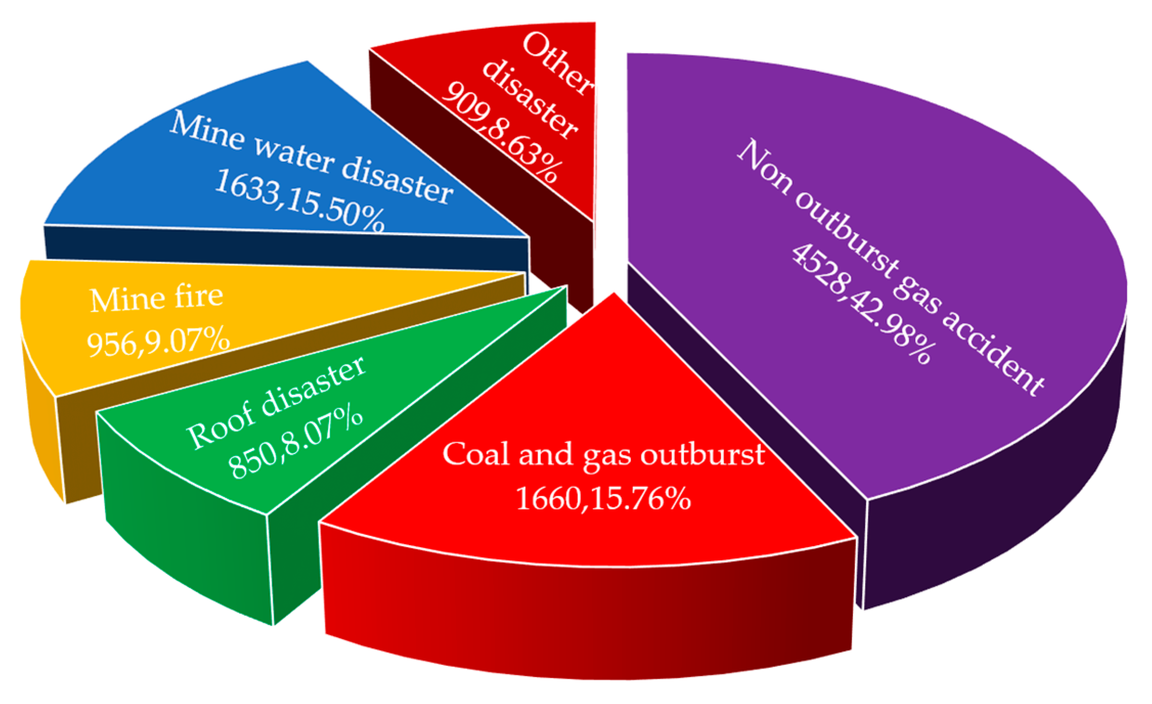
There were 750 gas accidents and 6188 fatalities among large accidents from 2005 to 2016, accounting for 53.6 and 58.7% of the total, respectively. This was far greater than those of other types of accidents. Secondly, roof disaster also has a large proportion. These accidents seriously affect safe and efficient mining (see Figure 1). [4,5,6,7,8]. The retained coal pillars for roadway protection are generally used in underground mining. Besides, human engineering disturbances are large in high-seam mining. Retaining the coal-pillar cannot guarantee the maintenance effect of roadways, which induces roof disasters and reduces the recovery rate of coal resources [9,10].

Figure 1.
Pie chart of the mine accident distribution.
The recovery rate of coal resources can be improved to extend the service life of mines in the case of pillar-free mining. The roadway roofs are ensured to be safe by eliminating the adverse effects of the coal-pillar stress concentration on mining [11,12,13]. According to the time–space relationship between the coal seam and roadway, pillar-free mining can be divided into cross-roadway pillar-free mining, goaf formation or excavation roadway pillar-free mining, and gob-side entry-retaining pillar-free mining. Gob-side entry retaining realizes Y-shaped ventilation to prevent gas accumulation in the corner. The gas channels are provided for the preliminary gas control of adjacent coal seams [14,15,16,17].
Many studies focus on the roadway layout and control technology of the pillar-free mining of soft coal seams in high gassy mines. Combined with the construction experience of Ningtiaota Mine, He et al. [18,19,20] proposed the four-step roadway process of supporting, cutting, protection, and sealing to systematically study the pressure distribution and evolution mechanisms of the working faces and roadways before and after the kerf of the pillar-free self-forming roadway. Roadway stability is enhanced using the self-supporting properties of the broken gangue and the synergistic support of surrounding rocks of the roadway in the goaf. Zhang et al. [21,22] put forward the technical idea of stress optimization in the surrounding rock zone of gob-side entry-retaining technology based on the feature analysis of overlying strata movement. The pre-splitting pressure-relief mechanism of the gob-side roof is explored to derive the key techniques including pre-split blasting pressure relief, zoning control, structural parameter optimization, “three-in-one” surrounding rock control, and rapid wall construction. Then, the beneficial engineering results are obtained.
Bai et al. [23] used numerical simulations to analyze the relationship among internal support, deformations, and stress distribution of surrounding rocks under the large uneven deformations and difficult maintenance of gob-side entry-retaining technology. High-resistance yield supports are adopted to improve the bearing capacity and deformation resistance of the surrounding rocks of gob-side entry-retaining technology, and it is successfully implemented in the Qinxin Mine. Yuan et al. [24,25] proposed a Y-shaped ventilation coal co-mining for the pillar-free gob-side entry retaining of first-mining pressure-relief seams based on years of innovations and practices in pressure-relief mining of low-permeability coal seams in the Huainan mining area. The new idea has developed the theory and key technology of pillar-free gas co-mining of coal seams with low permeability. Kang [26] took the gob-side entry-retaining technology in Xiejiaji, Huainan, as the engineering background. Numerical simulations are used to analyze surrounding rock deformations and stress distribution characteristics of the roadway, which explores the relationship among the basic support, reinforced support, and side support. The deep gob-side entry-retaining technology is different from the shallow gob-side entry-retaining technology in the roof fracture position, basic roof rotation, and long-term creep of surrounding rocks. The support design principles of deep gob-side entry-retaining technology are put forward.
At present, there have been many studies on the technology of goaf-retaining roadways without coal pillars. Most of them are aimed at improving the recovery rate of coal resources, and the control technology of the goaf-retaining roadway is relatively simple. However, there are relatively few comprehensive control technologies for pillar-free mining under complex conditions such as high gas mines and soft thick coal seams. Taking the w1319 pillar-free working face of the Gaohe Coal Mine as the background, this work studied the roadway layout and roadway retention control technology of the working face in the soft thick coal seam of high gas mines using theoretical analysis, numerical simulations, field investigations, and field measurements, which can provide a useful reference for similar projects.
2. Engineering Background
The No. 3 coal seam is mined in the Gaohe Coal Mine of Lu’an mining area. The average buried depth of the coal seams of the W1318 and W1319 working faces is 410 m The two working faces are arranged in a north–south direction, and advanced in an east–west direction. The layout lengths of the W1318 and W1319 working faces are 273 and 340 m, respectively; the advancing lengths are 1040 and 630 m, respectively. The middle of the two working faces is the Beilimo anticline. The coal seam has a slope of 1–7° (with an average of 5°) and an average thickness of 6 m. There is a dirt band in the coal seam. The roof consists of mudstone, sandy mudstone, and fine-grained sandstone; the floor consists of mudstone, sandy mudstone, and siltstone. It is a high gassy mine with an absolute gas emission quantity of 269.28 m3/min.
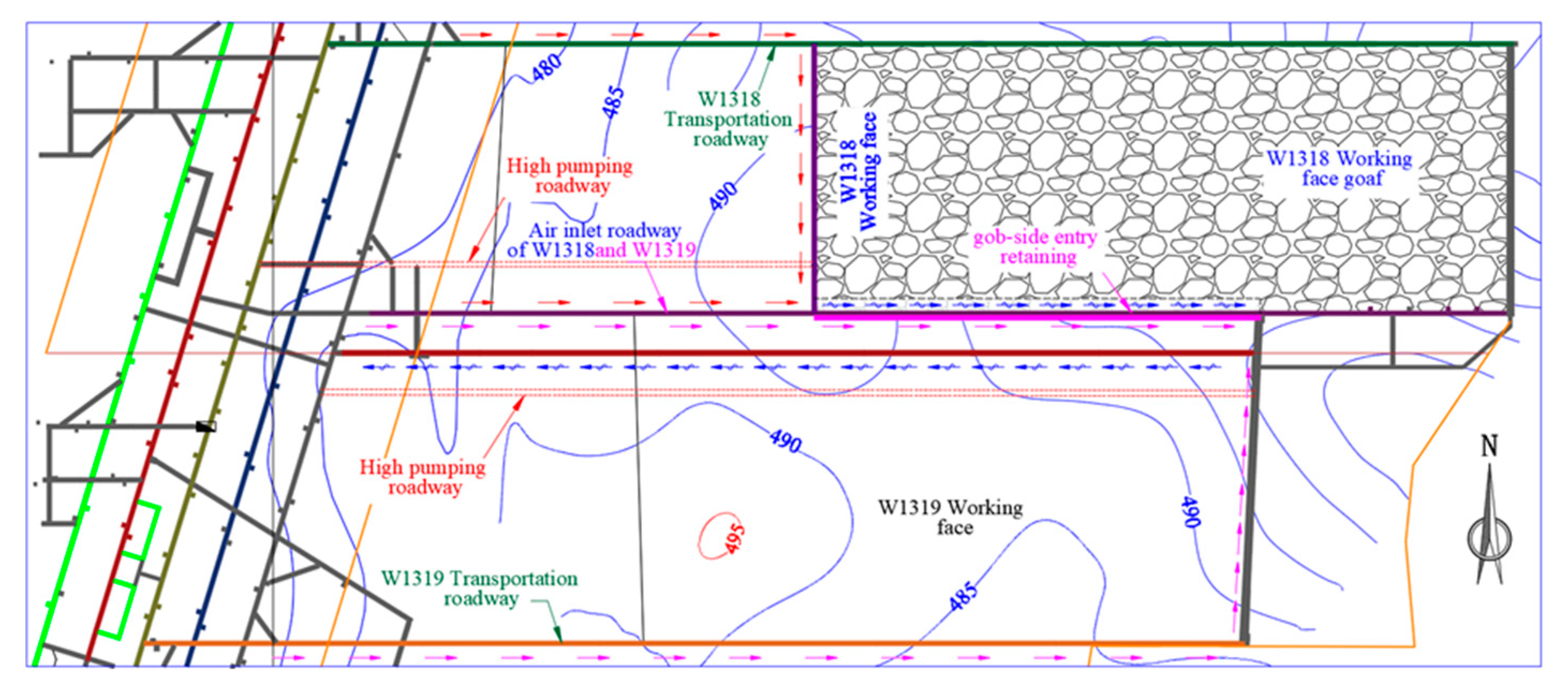
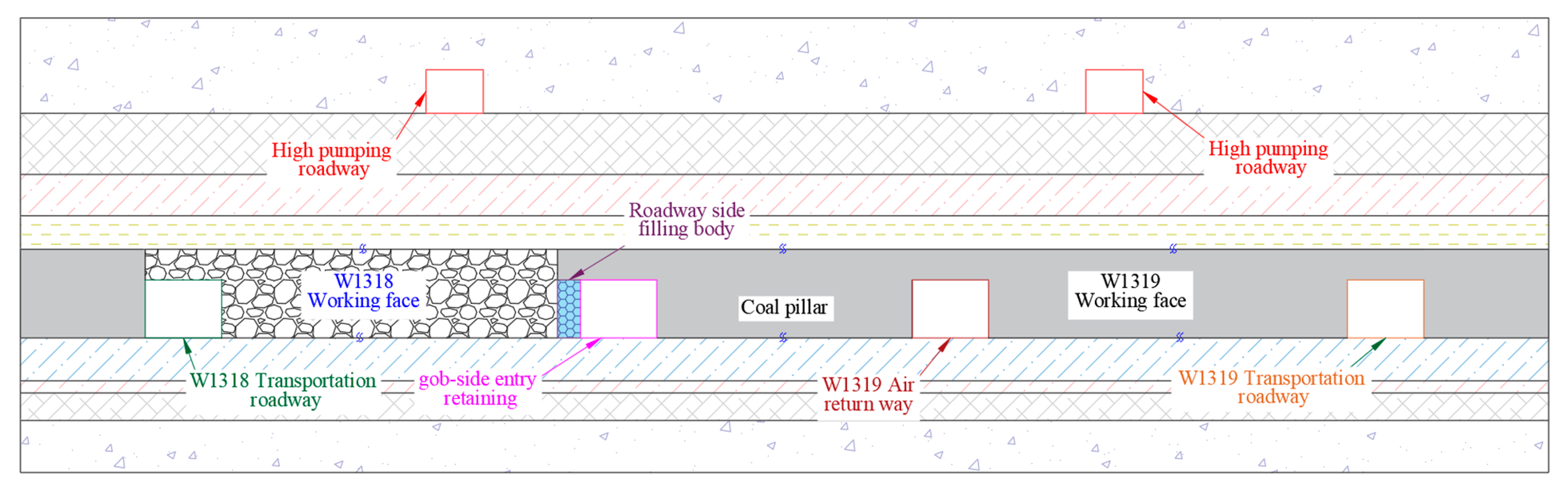
The stoping of the W1318 working face adopts Y-shaped ventilation to achieve safe and efficient mining in high gassy mines (see Figure 1). The W1318 belt and air intake grooves are used for air intake. Gob-side entry-retaining technology is used as an air intake groove for returning air and as the air intake groove of the W1319 working face. Gob-side entry-retaining technology and belt grooves are used for air intake in mining the W1319 working face, and the air return groove is used for returning air, which forms W-shaped ventilation. The air intake groove of the W1319 working face is for gob-side entry-retaining technology. The coal pillar with a certain width is reserved between the gob-side entry-retaining technology and the return airway of the working face. The coal pillar is directly recovered to realize pillar-free mining in the stoping of the W1319 working face (see Figure 2). High-pumping roadways are arranged on the roof for gas extraction, which prevents gas accumulation in the goaf.
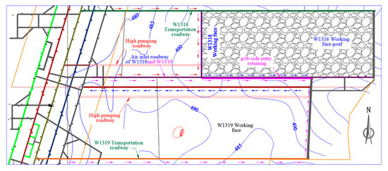
Figure 2.
Layout of working faces and roadways.
The gas in the goaf is controlled to ensure the surrounding rocks’ stability for the gob-side entry-retaining technology, the W1319 return airway, and the high-pumping roadways of two working faces. It is necessary to explore the width of the reserved coal pillar, the reasonable horizon, and the location of the high-pumping roadway in the W1319 non-coal-pillar mining working face. The surrounding rocks of the gob-side entry-retaining technology are disturbed three times. Therefore, it is difficult to control the surrounding rocks of the roadway. The control technology of gob-side entry-retaining technology is studied in a targeted manner to ensure the safe and efficient mining of coal resources.
The gob-side entry-retaining technology with a rectangular section is supported by anchor mesh cables and ladder beams. The anchor rod is made of Φ 22 × 2400 mm left-handed non-longitudinal rib-threaded steel, with the form of end anchoring. The roadway adopts high-strength, low-relaxation steel strand anchor cables, with a diameter of Φ 18.96 mm and lengths of 8300 and 4500 mm, respectively. The ladder beams are made of round steel with a diameter of Φ 14 mm. Figure 3 shows the cross-sectional view of the roadway support.
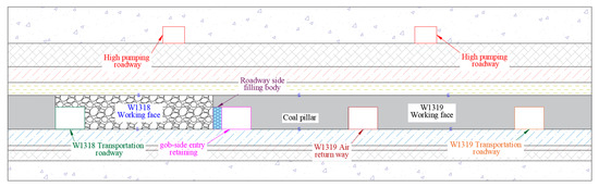
Figure 3.
Layout of the roadway horizon relationship.
The W1319 intake airway has a net width of 4000 mm, a net height of 3850 mm, and a net section of 15.4 m2 (see Figure 4). There are eight anchor rods in each row of the roof, with a spacing of 800 × 900 mm. The first anchor rod near the coal-pillar side is located at an inclination of 20° from the vertical direction, and the top plate anchor cables are set vertically, with four cables in each row, a spacing of 1400 mm, and a row spacing of 900 mm. The side of the air inlet groove is supported by a flexible wall, and five anchor rods are set on the coal-pillar side with a spacing of 900 * × 900 mm. The first anchor rod in the upper part is set at an inclination of 20° from the vertical direction. The floor anchor rod is set at an inclination of 10° downward. Reinforced anchor cables of 4.5 m (4500 mm) are installed on the coal-pillar side. The upper anchor cables are set vertically, with two cables in each row, a spacing of 1400 mm, and a row spacing of 1800 mm.
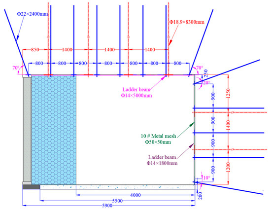
Figure 4.
Cross-sectional view of the roadway support.
3. Analysis of Reasonable Reserved Size of Coal Pillars
The intake airway of the W1318 working face adopts the gob-side entry-retaining technology. The retained roadway is used for air return of the W1318 working face. Besides, it is used as the intake airway in the stoping of the W1319 working face. The mining roadway of the W1319 working face is excavated in advance in the stoping of the W1318 working face to avoid discontinuous excavation. A coal pillar with a certain width is reserved between the W1318 gob-side entry-retaining technology and the W1319 return airway.
When the reserved coal-pillar width of the W1319 working face is too small, the return airway is greatly deformed due to the influence of the adjacent working face, which cannot guarantee stable applications during the service period. When the reserved coal-pillar width is large, there is a large workload of cross-excavation between the return and intake airways of the working face. Therefore, it is necessary to analyze the reasonable reserved width of coal pillars.
The coal-pillar width of the roadway is calculated according to the coal-pillar strength by Bernauth-Kin (1969), and the strength values of the critical cube and standard specimen of the coal laboratory by Hestry (1976) [27,28,29]. Hurstry (1976) derived the relationship between the cube of the critical magnetic field (the length of the key pillar is greater than 0.9 m), the uniaxial compressive strengths of coal laboratory specimens, and parts based on the Gaddg formula.
where σc is the uniaxial compressive strength of the laboratory specimen, MPa; σm is the uniaxial compressive strength of the critical cube specimen, Mpa; D is the diameter of the laboratory specimen or the side length of the cube, m.
The length of the critical cube is 0.9 m, and the diameter D of the standard specimen in the laboratory is 0.05 m. The relationship between σm and σc after calculation can be expressed as follows.
According to the calculation Equation of coal-pillar strength by Bernabeuth-King (1969),
where σp is the coal-pillar strength, Mpa; W is the coal-pillar width, m; h is the coal-pillar height, m.
The load on the coal pillar is the original crustal stress. The load intensity q of the coal pillar is expressed as follows.
where q is the static load intensity of the coal pillar, kN/m3; qz is Heim’s hydrostatic load, kN/m3; qn is the load of overlying strata on the coal pillar according to composite beam theory.
According to Heim’s hydrostatic pressure theory.
where qz is Heim’s hydrostatic load, kN/m3; γ is the density of overlaying strata, 26 kN/m3; H is the buried depth, m.
The loads on any stratum in the mining overlying strata include their weights and the loads caused by the upper overlying strata. It is assumed that the strata loads are uniformly distributed for analysis. The upper and lower strata deform synchronously to form a composite beam structure under uniform loads. The load of the coal-rock mass under the key layer on the coal mass can be calculated according to the composite beam theory [30,31]. The engineering geological conditions of the W1319 working face of Gaohe Energy are used to obtain Equation (5) according to the composite beam theory.
where (qn)1 is the load on the first layer when the nth layer is considered, Mpa; Ei is the elastic modulus of the ith layer, Mpa; hi is the thickness of the ith layer, m; γi is the bulk density of the ith layer, MN/m3.
According to the composite beam theory, if the load on a certain stratum is smaller than that on the adjacent upper stratum, then the stratum is the key layer with a large thickness and a high strength. This stratum can control partial mine pressure and has no loading effect on the first layer. Loads on each roof of the coal seam can be calculated step by step in this way. When the combined beam theory is used to calculate the loads of coal and rock masses, it is necessary to master the basic mechanical parameters of coal and rock mass in the stope. The mechanical parameters of coal and rock masses in the stope are obtained through field sampling and laboratory tests (see Figure 5). According to the combined beam theory and the distribution and mechanical properties of coal and rock masses in the stope, the direct load on Gaohe coal seam 3# is calculated to be 0.10 Mpa. The load of the upper stratum on the coal seam is 0.212 Mpa according to the composite beam theory. Table 1 shows the specific stratum parameters and loading conditions.
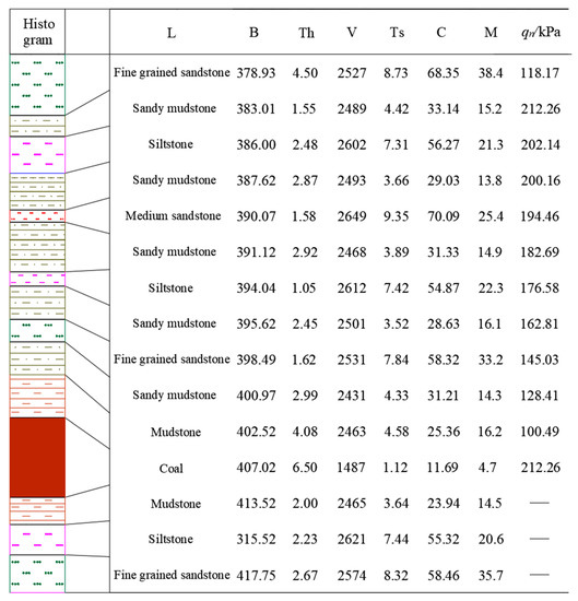
Figure 5.
Stratum parameters and loading conditions. Note: L: lithology; B: burial depth; Th: thickness; V: Volumetric force; Ts: tensile strength; M: modulus of elasticity; C: compressive strength; qn/kPa: load on rock stratum.

Table 1.
Fracture development at different lengths of the working face.
4. Numerical Analysis of Reasonable Space Layout and Control of the Roadway
The reserved coal-pillar width of pillar-free mining in high gassy mines is preliminarily studied through theoretical analysis in the above section. Reasonable sizes of reserved coal pillars are determined by numerical simulations to analyze the growth height of the fracture zone in the pillar-free working face. Then, the horizon and position of the high-pumping roadway are determined, combined with the discrete element simulation and site-specific conditions. It is not easy to control the surrounding rocks of gob-side entry-retaining technology. Therefore, technical measures for roof cutting reinforcement are proposed according to the roadway opening and layout in the pillar-free working face.
4.1. Determination of a Reasonable Coal-Pillar Width
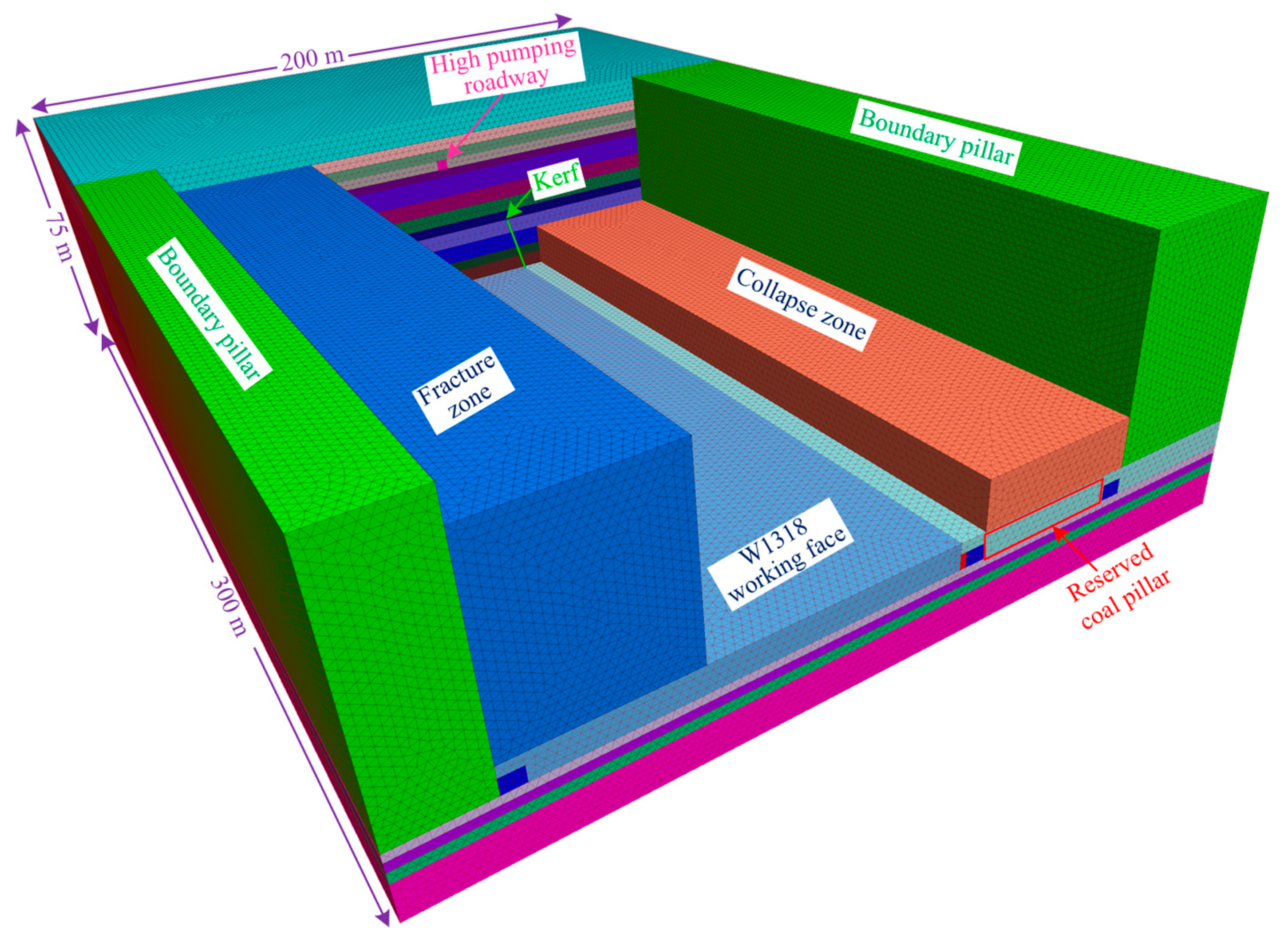
The finite-difference numerical simulation software FLAC3D is used to study the reasonable size of the reserved coal pillars in the high gassy mine according to the engineering geological conditions and coal-rock mechanical parameters of the W1319 working face of Gaohe Energy. Rhino5.0 is used to establish the calculation model (see Figure 6). The modeling size is 200 × 300 × 75 m, and griddle software is used to divide the simulation grid. According to the buried depth of the coal seam and the modeling height, 8.75 mpa stress is applied to the top of the model to simulate the unit weight of the overburden, and 12-Mpa horizontal stress is applied around the model to simulate horizontal stress (measured horizontal in situ stress is 12 Mpa).
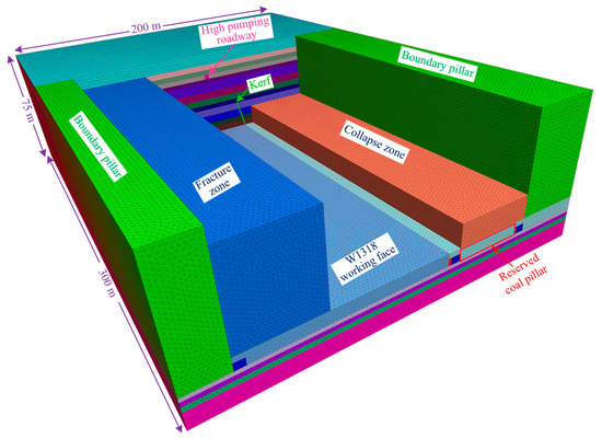
Figure 6.
Numerical simulation model.
The gradual load along the Z direction is applied on the left, right, front, and rear boundaries of the model according to the relationship between horizontal stress and vertical stress. The boundary coal pillar is reserved at the boundary of the model to eliminate the boundary effect. The reserved crack is set upward at the top angle of the w1318 air inlet tunnel within 150–300 m in the Y direction in the model, which is used to simulate roof cutting and pressure relief at the later stage. The Moore Coulomb constitutive model is used as the failure criterion of coal and rock masses in the model.
The working surface is arranged along the X direction and advanced along the Y direction in the model. There is the boundary pillar, W1318 working face transportation groove, W1318 working face, reserved backfill module of the gob-side entry-retaining technology, W1318 intake airway (gob-side entry-retaining technology for W1319 air intake), reserved coal pillar, return airway of W1319 working face, and W1319 working face, from left to right in Figure 6. The model is excavated 30 times, and the working face advances 10 m each time. The roadside backfill module is excavated synchronously in the excavation process. The reserved backfill module of gob-side entry-retaining technology is endowed with the parameters after excavation by the filling command to simulate roadside backfilling.
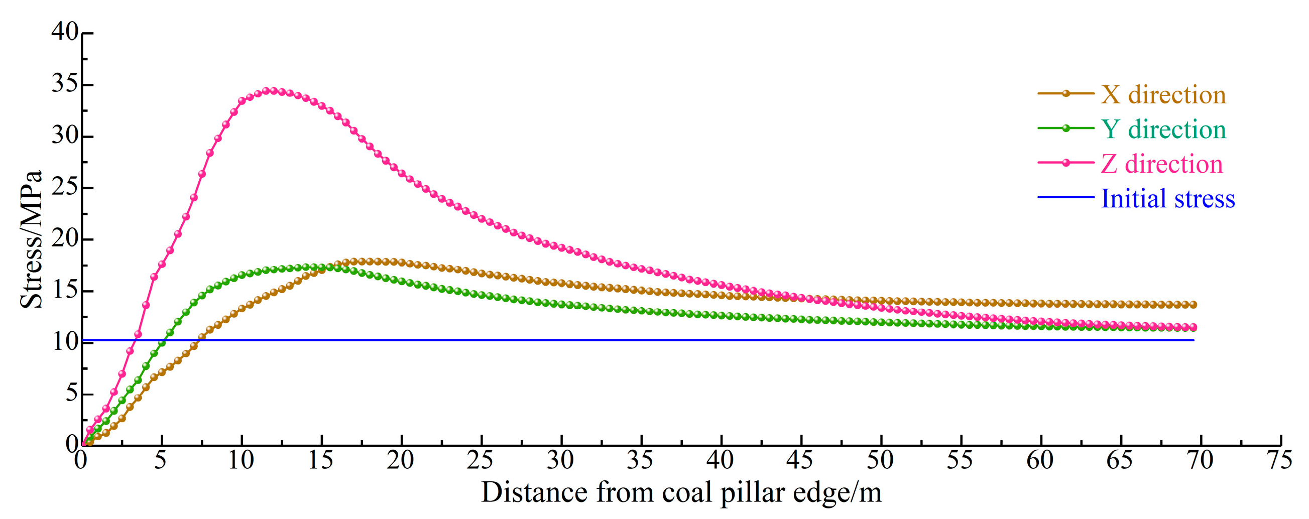
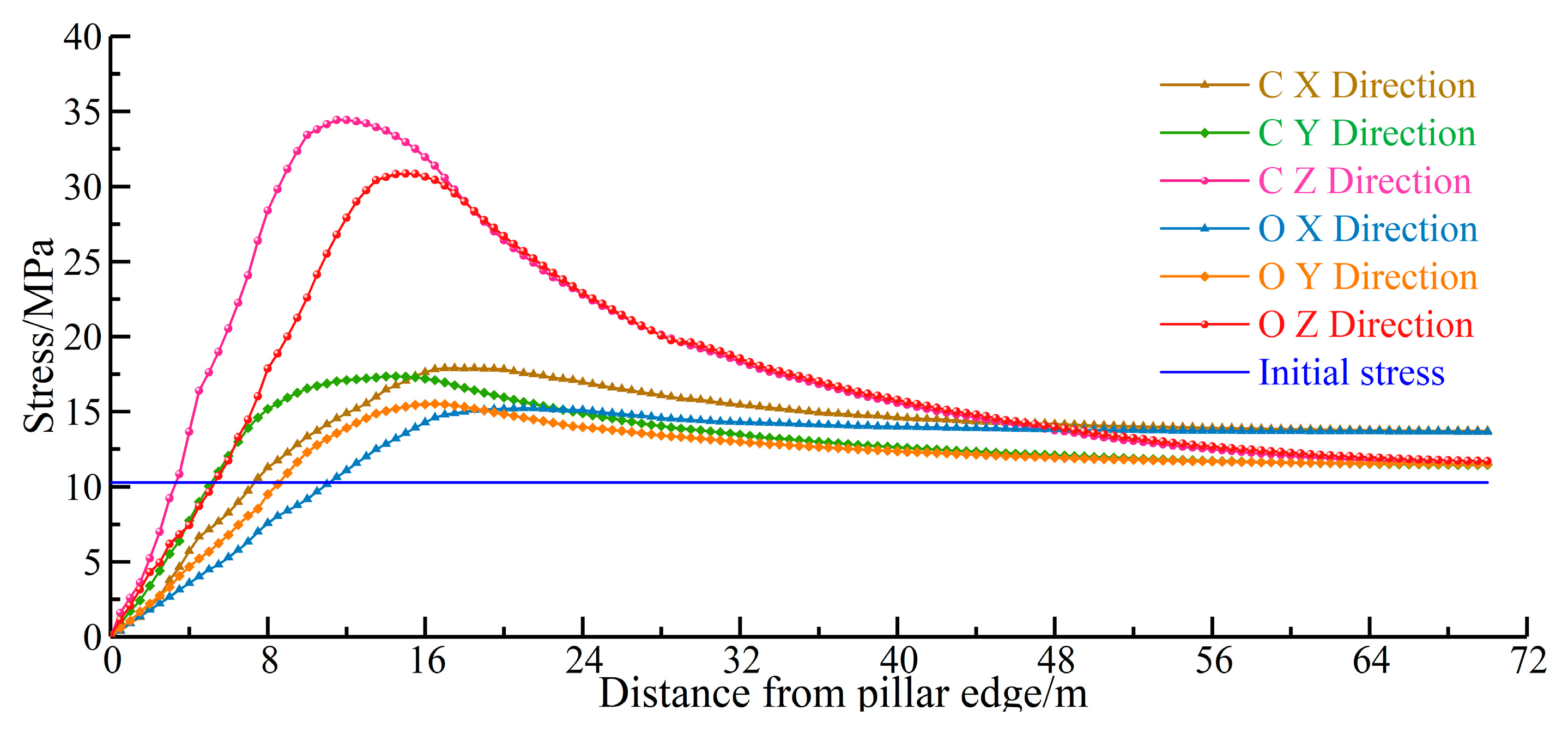
The cantilever beam forms lateral stress in the coal pillar on the side of the working face during the rotary sinking process after the stoping of the working face (see Figure 7). The stress peak in the Z direction of the side coal pillar is 11.5 m away from the coal pillar’s edge; the stress peak value is 34.44 Mpa; the original rock stress is 10.27 Mpa; the stress concentration factor is 3.35. The concentration factor of vertical stress is less than 2, with a slow reduction rate outside the scope of 27 m on the side of the working face. The peak value of horizontal stress is about 15 m away from the coal pillar’s edge; the peak value of stress concentration is 17.5 Mpa; the stress concentration factor is 1.70. Compared with vertical stress, horizontal stress has a flat change in concentration.
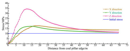
Figure 7.
Lines of lateral stress distribution.
Therefore, vertical stress is used as the main reference for the roadway layout on the side of the working face. The roadway can be arranged outside the scope of 27 m to reduce the impact of mining on the side roadway. The surrounding rock’s plasticization and deformation of the roadway are simulated when the roadway is 30 and 35 m from the coal pillar’s edge.
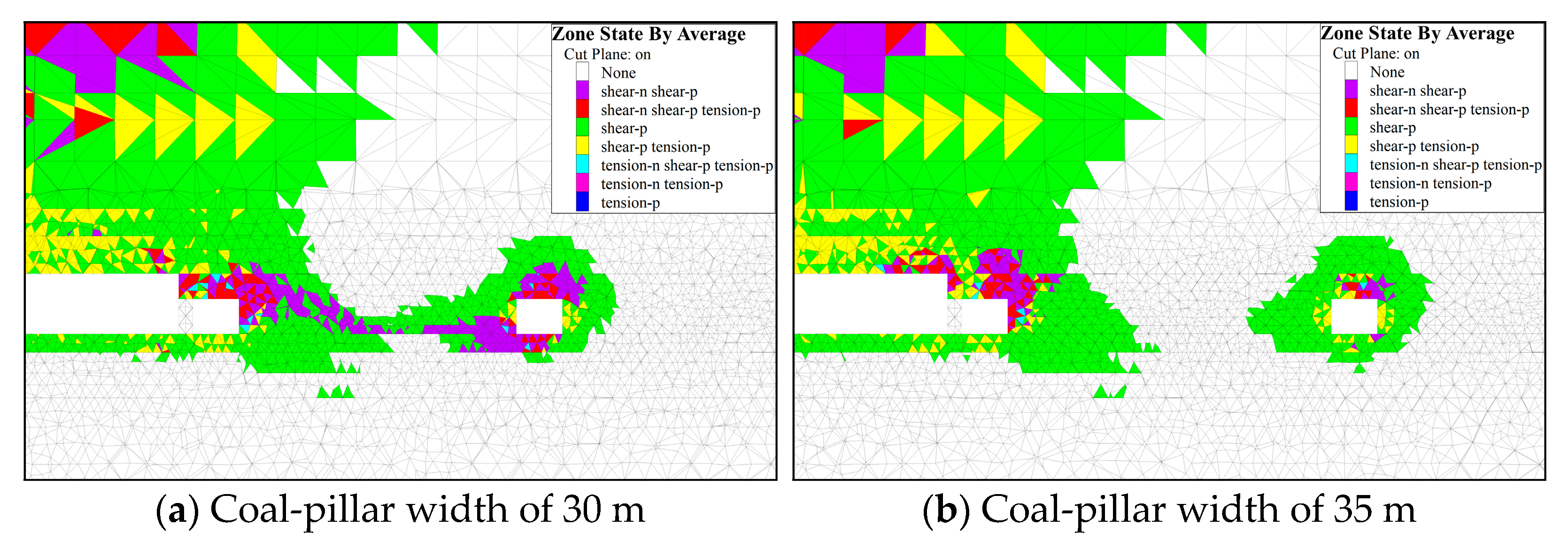
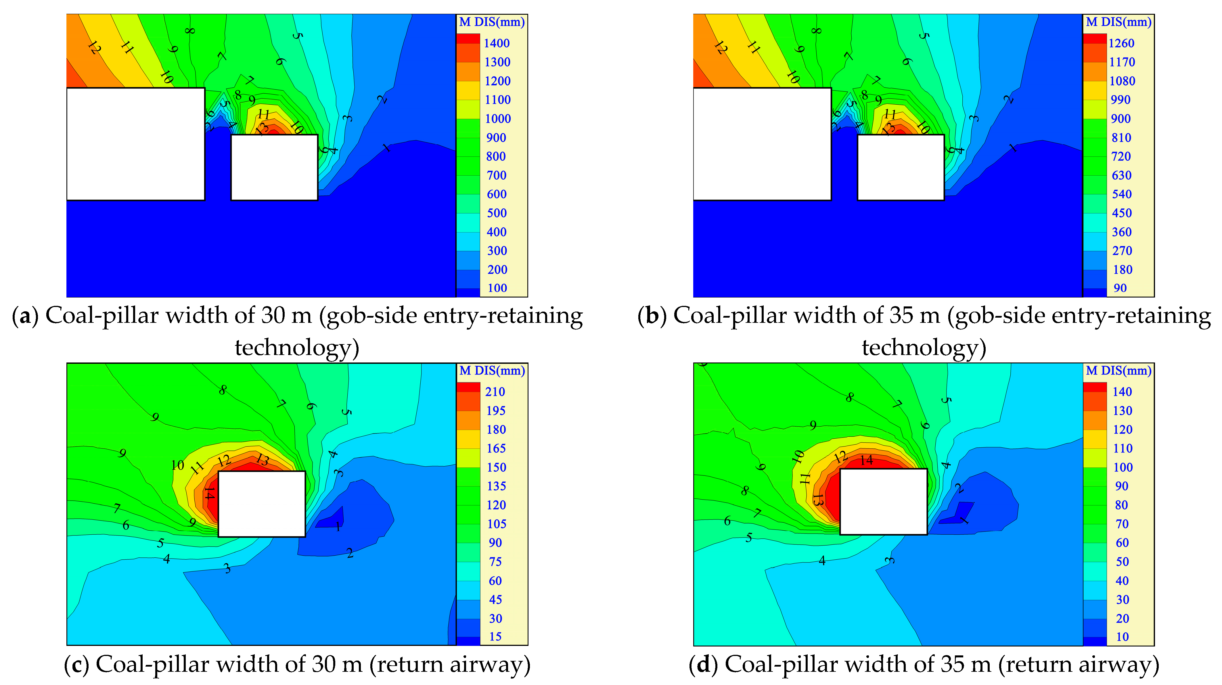
When the coal-pillar width is 30 m, the coal-pillar plastic development zones between the W1318 gob-side entry-retaining technology and W1319 return airway are connected after the stoping of the W1318 working face. When the coal-pillar width increases to 35 m, an elastic zone of about 10 m appears between the coal pillars (see Figure 8), Coal pillars are stable, and the surrounding rock deformation across the roadway is easily controlled by the coal pillar. When the coal-pillar width is 30 m, the maximum roof subsidence of the gob-side entry-retaining technology is 1422 mm (see Figure 9), with large deformations of floor and roadside backfill. The maximum roof subsidence of the return airway is 212 mm, and the maximum subsidence on the left side of the roadway is 214 mm. A slight deformation appears on the right side and floor of the return airway, with a maximum floor heave volume of 75 mm. When the coal-pillar width is 35 m, the surrounding rock deformation of the gob-side entry-retaining technology decreases with the weakened plastic failure of the coal pillar and return airway. The maximum roof subsidence is 1301 mm and decreases by 8.5%. The surrounding rock deformation of the return airway is controlled. The maximum roof subsidence is 146 mm, which is 31% less than that of the 30 m coal pillar. Based on the simulation results, the reserved coal-pillar width of the working face is determined to be 35 m.

Figure 8.
Plastic development of return airway at different reserved coal-pillar widths.
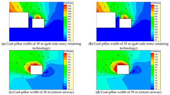
Figure 9.
Displacement deformations of the roadway under different coal-pillar widths.
4.2. Mathematical Analysis of the Reasonable Layout of High-Pumping Roadways
The roadway layout and reserved coal-pillar size in the coal seam are studied to determine the control measures for entry retaining by roof cutting. More roadways are excavated to achieve better ventilation and gas control. Besides, high-pumping roadways are set to drain gases in the goaf. The layout level and area of the high-pumping roadway directly determine the gas drainage effect in the goaf. If the high-pumping roadway is arranged at a high level, the drainage effect is unsatisfactory. If the layout level is low, the roadway will be seriously deformed. Therefore, theoretical analysis and numerical simulations are used to determine the layout level and area of the high-pumping roadway. The high-drawing roadway is generally arranged in the fracture zone, which is expressed as follows [32].
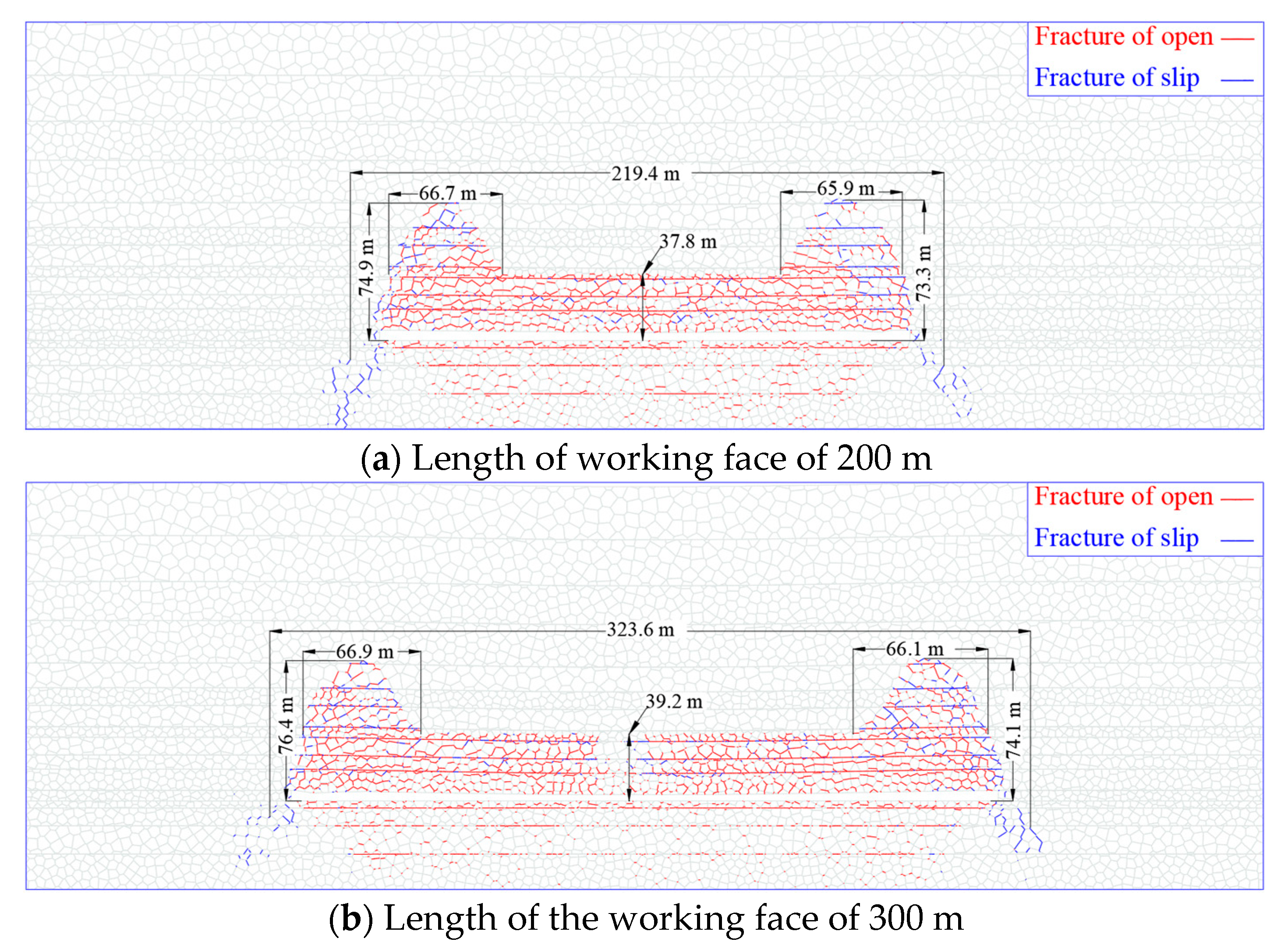
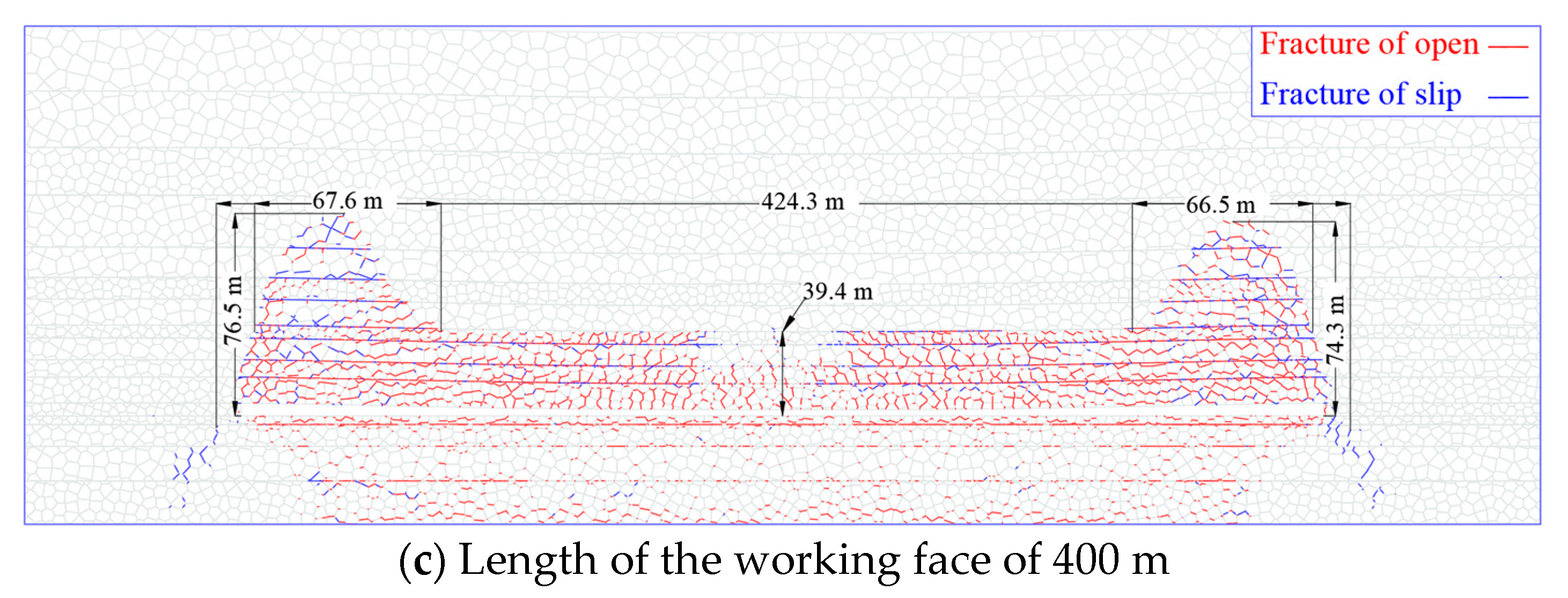
Equations (6) and (7) are used to calculate the height of the fissure zone according to the soft-roof and medium-hard rock layers, respectively. The average coal thickness of the W1319 working face is 6.5 m. Mudstone and sandy mudstone are soft strata on the coal-seam floor; the siltstone and fine-grained sandstone are medium-hard strata. The heights of the fracture zone are calculated to be 21.8–29.8 and 40.85–52.05 m according to soft and medium-hard strata. Therefore, the average value is 36.92 m. The 2D discrete element simulation software UDEC is used to explore the development height of the fracture zone by combining the coal-seam distribution with the physical and mechanical parameters of the W1319 working face of Gaohe Energy due to the deficiencies in finite difference software. The stress of 6.0 MPa is applied to the top of the model to simulate the unit weight of the overburdens. The boundary conditions applied by the model are the same as those of FLAC. Figure 10 shows the simulation results.
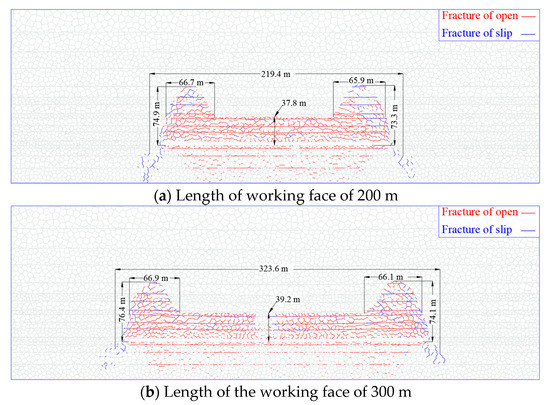
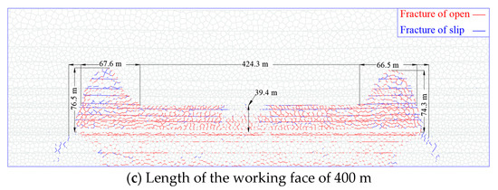
Figure 10.
Development heights of the fracture zone under different lengths of the working face.
Overlying strata are provided with activity space after the stoping of the working face. There are caving, fracture, and curved subsidence zones in the stope from bottom to top. The fracture developments are different in different regions of the fracture zone. Overlying strata on both sides of the working face generate slippage and opened fractures after rotary sinking. Fractures in this region are highly developed. Overlying strata in the middle of the working face subside as a whole. Some opened fractures are developed for re-compaction. The height of the fracture is small after stabilization, which presents a saddle-shaped development. Table 1 shows the fracture development in different regions.
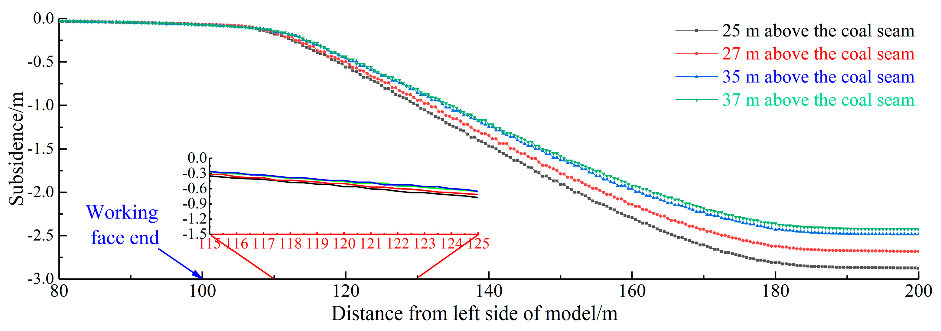
The width and height of the saddle peaks on both sides of the fracture zone are about 66.5 and 75.5 m, respectively, after the stabilization of fracture development. The fracture-development height in the middle of the working face is 39.2 m. The monitoring data of the survey lines, which are 25, 27, 35, and 37 m above the working face, are derived to draw the subsidence curves (see Figure 11).
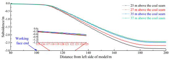
Figure 11.
Subsidence Curves.
The subsidence of the overlying roof strata decreases from bottom to top after the stoping of the working face, and it increases from the working face’s end to the middle area. Subsidence achieves its maximum about 80 m from the end. The overall roof subsidence is small, from 115 to 125 m, and the adjacent layers have similar rock-mass subsidence. The saddle peak of the fracture zone is about 60 m away from the end. The high extraction roadway is arranged in this area to easily control the stability of the surrounding rocks, which extract adequate gases.
4.3. Mathematical Analysis of Pressure Relief Reinforcement of Gob-Side Entry-Retaining Technology
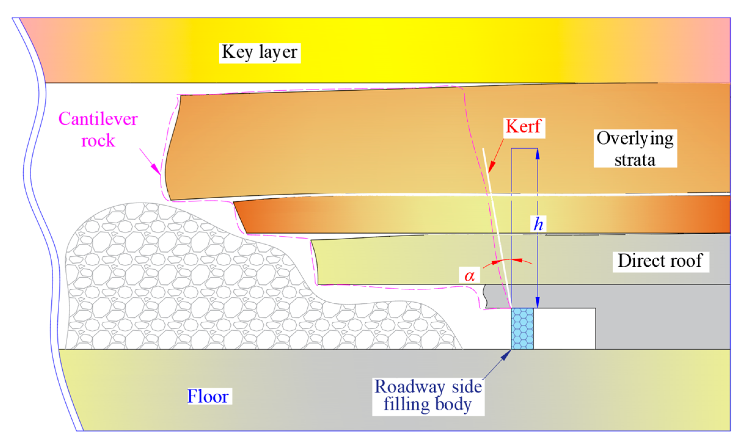
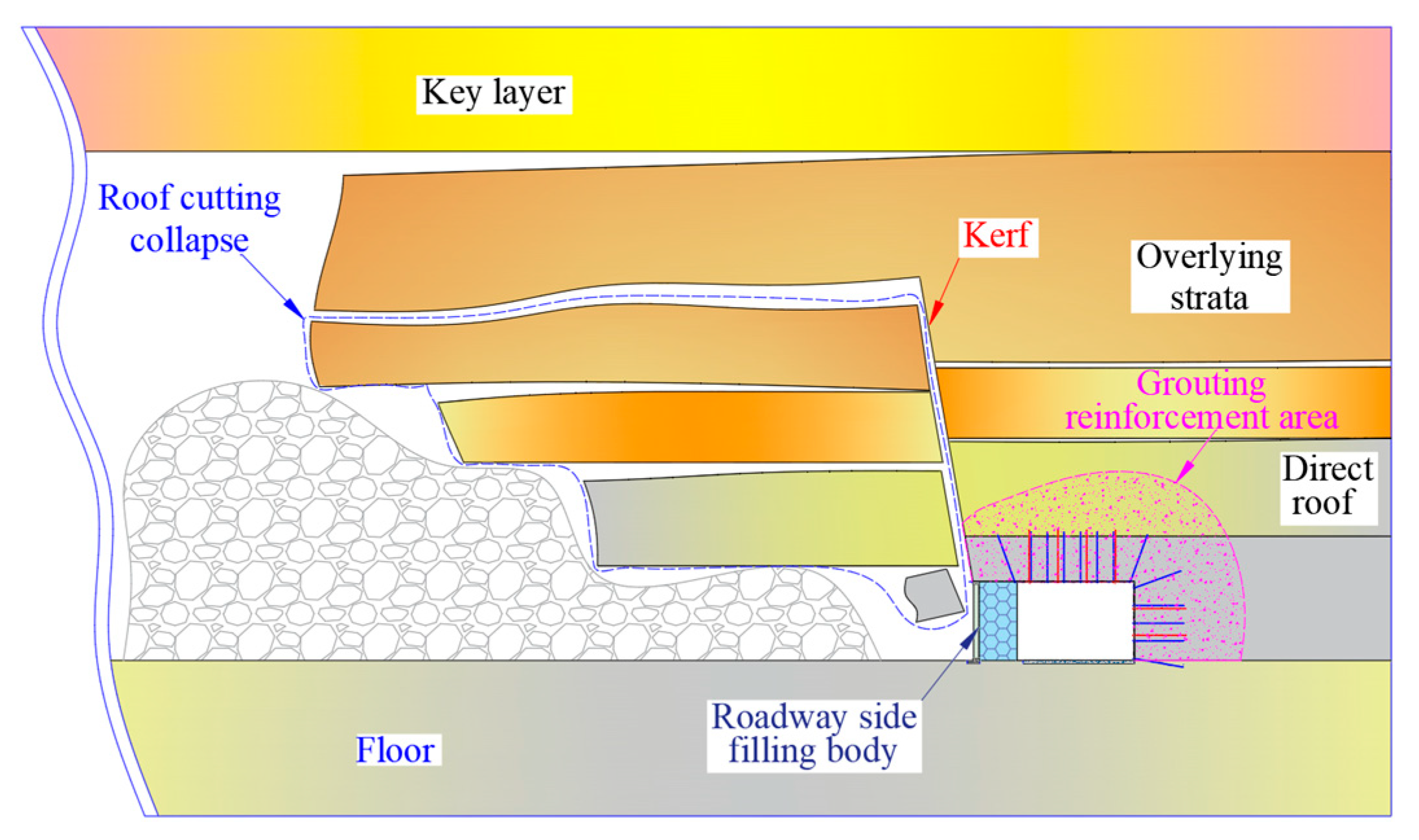
The reserved coal-pillar width of the pillar-free working face was 35 m when gob-side entry-retaining technology was adopted in the previous research. However, the surrounding-rock deformation of the gob-side entry-retaining technology is large, which cannot guarantee safety and stability during the service period. This section focuses on the stability control technology for the surrounding rocks of roadways. A large amount of free space appears under the overlying strata after the stoping of the working face. Therefore, the overlying strata fail to collapse. However, both ends of the working face are supported by the lateral coal mass to form a cantilever beam structure on the side of the boundary coal pillar. The outwardly extending part of the cantilever beam produces huge stress on the coal pillar and roadway understrata in the rotary sinking process. Meanwhile, the cantilever beam transmits force generated from the subsidence of the upper overlying strata [33]. Therefore, cantilever rocks collapse freely by roof cutting, which eliminates the force generated from rotary sinking and weakens the stress of the upper overlying strata (see Figure 12).

Figure 12.
Cantilever beam structure.
The caving and the fracture zones appear from bottom to top after mining coal seams. Swelled rock masses fill the goaf to bear overlying strata due to the swellability after caving. The height of the caving zone is calculated as follows.
Mudstone and sandy mudstone above the W1319 working face are soft strata; fine-grained sandstone and siltstone in the roof are medium-hard strata. Equations (8) and (9) are used to calculate the height of the caving zone according to the soft roof and medium-hard strata, respectively. The heights of the caving zone are 7.49–10.49 and 10.91–15.31 m, according to the soft and medium-hard strata, respectively. The roof cutting height can be positioned at 15.3 m to ensure the roof cutting effect. Therefore, the kerf height is also set to 15.3 m in the numerical simulation model. The stability of the surrounding rocks of the roadway is simulated after pressure relief by roof cutting.
Vertical stress has the largest change after pressure relief by roof cutting, and horizontal stress changes gently. The lateral stress peak of the working face shifts outward. The maximum peak is 15 m away from the coal pillar’s edge, and the maximum vertical stress is 30.85 MPa (see Figure 13). The lateral stress concentration factor is less than 2 at 29 m away from the coal pillar’s edge. The area where the lateral stress recovers to the stress state close to the original rock is farther from the edge of the coal pillar than when the roof is not cut. The area is farther from the coal pillar’s edge. Therefore, the reserved coal-pillar width is still set to 35 m.

Figure 13.
Lateral stress distribution curves after pressure relief by roof cutting.
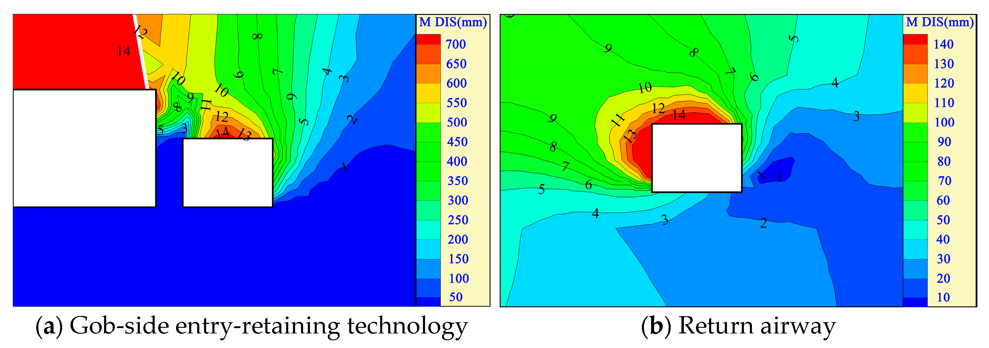
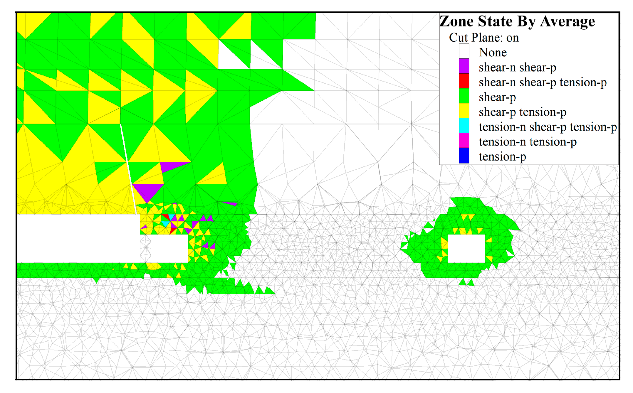
The plastic development of surrounding rocks weakens after the roof cutting with the gob-side entry-retaining technology. The plastic development degree of the surrounding rocks in the return airway increases due to the influence of lateral stress (see Figure 14). The surrounding rocks of the gob-side entry-retaining technology have the maximum subsidence of 733 mm after roof cutting, which is 48.5% less than the roof subsidence of the roadway before roof cutting. The floor heave of the gob-side entry-retaining technology has also been controlled. The maximum subsidence of the roof is 144 mm, and the maximum deformation of the left side is 146 mm for the surrounding rocks of the return airway (see Figure 15). The surrounding rocks of the gob-side entry-retaining technology are stabilized after roof cutting. However, the stability of the surrounding rocks of the return airway cannot be controlled. Therefore, the gob-side entry-retaining technology is further reinforced to control the surrounding rocks’ deformation.
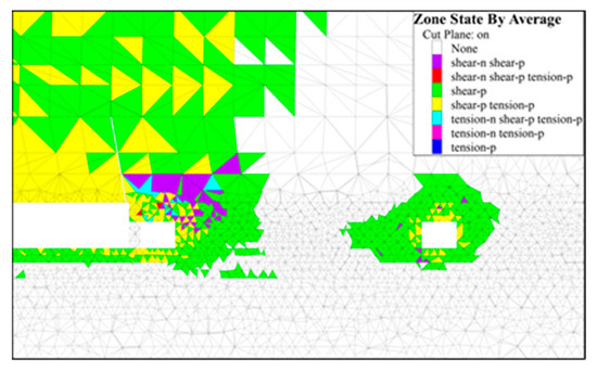
Figure 14.
Plastic development of surrounding rocks after roof cutting.

Figure 15.
Roadway deformations after roof cutting.
4.4. Grouting Reinforcement Technology of the Surrounding Rocks of the Roadway
The results of discrete element simulations show that numerous fractures developed in the coal pillars on two sides, the roof and floor, after the stoping of the working face. The bearing capacity greatly decreases for coal-rock masses in a broken state. The broken surrounding rocks of the gob-side entry-retaining technology have been controlled after pressure relief by roof cutting. The grouting reinforcement technology is adopted to improve the strength of coal-rock masses, which stabilizes the surrounding rocks of the roadway during the service period. Make the surrounding rock of the roadway a whole, and further ensure the stability of the goaf retaining roadway and the return air roadway of w1319 working face
Grouting materials are injected into fractures of broken surrounding rocks through the coal pillars and roof at a certain pressure in the grouting reinforcement process. Broken coal masses are bonded to integrate the original support system with the sides and roof of the roadway. The deep and shallow hole grouting is adopted (see Figure 16). The fractures of the coal-rock masses are developed under stress in the shallow hole-grouting area, where coal masses completely lose their bearing capacity. Broken rock masses are bonded with slurries to improve the physical and mechanical strength of coal-rock masses in this area. Broken rock masses and the original support system constitute an anchoring composite carrier to avoid the failure of bolt cables in the loose rock masses. Support strength is improved to prevent the deformations and failure of surrounding rocks [34,35,36,37,38].
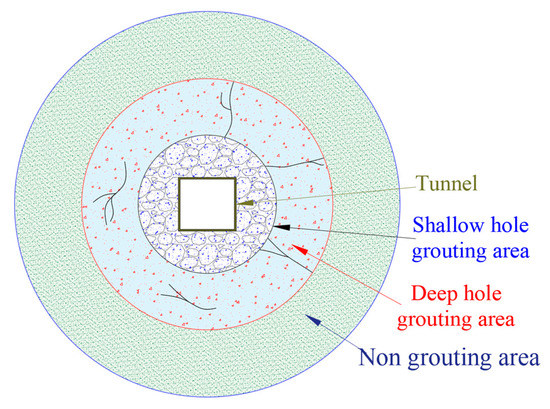
Figure 16.
Roadway deformations after roof cutting.
The deep hole grouting area is located in the deep part of the surrounding rocks. It has a certain bearing capacity, with less-developed surrounding fractures. The fractures in the surrounding rocks are filled with slurries to improve their bearing capacity, which controls the deformations and failure of the surrounding rocks induced by multiple mining disturbances. The bearing capacity of the surrounding rocks is greatly improved by the deep and shallow hole grouting for the stable use of the retained entry during the service period. Figure 17 and Figure 18 show the numerical simulations after roof-cutting reinforcement and roof cutting, respectively.

Figure 17.
Plastic development of surrounding rocks after roof-cutting reinforcement.
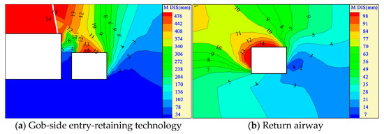
Figure 18.
Roadway deformation after roof cutting.
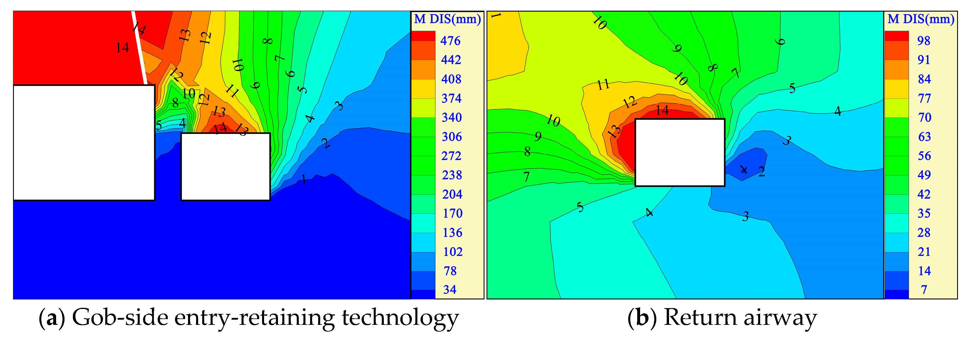
Coal pillars and the roof of the gob-side entry-retaining technology are reinforced by grouting to integrate the broken surrounding rocks with the support system. An anchoring composite carrier is formed to greatly improve the bearing capacity of the surrounding rocks of the roadway. Besides, the plastic failure area of the surrounding rocks of the gob-side entry-retaining technology significantly weakens. The plastic development degree of the return airway decreases greatly due to the good support effect of coal pillars on the roadway roof.
The maximum roof subsidence of the gob-side entry-retaining technology is 482 mm after grouting reinforcement; the maximum deformation of the coal-pillar side is 170 mm; the deformations of the floor and roadside backfill are less than 100 mm. The maximum roof subsidence of the return airway of the W1319 working face is 102 mm; the maximum deformation of the left side of the roadway is 103 mm; the deformations of the floor and the right side of the roadway are about 35 mm. The plastic development and deformation of the gob-side entry-retaining technology and return airway are within a controllable range, which ensures the safe and stable use of the roadway during the service period.
5. Discussion
The thick-seam high-gas working face has been conducted with pillar-free mining in previous research. Gases are extracted by the high-pumping roadway and Y-shaped ventilation of the gob-side entry-retaining technology in the stoping of the first working face. They are controlled by the high-pumping roadway and W-shaped ventilation of the gob-side entry-retaining technology in the first working face in the stoping of the second working face. The most critical factors for pillar-free mining are the layout of the high-pumping roadway, the spatial position relationship of mining roadways, and the surrounding rocks’ control of the gob-side entry-retaining technology.
According to the theoretical analysis and discrete-element numerical simulations, the height of the fracture zone is about 38 m; that of the saddle peak of the fracture zone is about 75.5 m; the width of the saddle peak is about 66.5 m. The roof has rotary sinking within 30 m from the end of the working face. However, the overall subsidence is not large. The subsidence difference between strata, which are 35 and 37 m above coal seams, is less than 2 cm. The fracture development is serious in the area. Therefore, the high-pumping roadway can be arranged at 20 m from the end and 35 m from the coal seam.
The high-pumping roadway of the W1318 working face is arranged at 20 m from the intake airway in terms of the changes in the coal strata of the W1318 and W1319 working faces; the high-pumping roadway of the W1319 working face is arranged at 20 m from the W1319 return airway. The reserved coal-pillar width of the working face is determined to be 35 m after the theoretical analysis and finite-difference numerical simulations. The pressure relief technology by roof cutting is used to control the surrounding rock deformation of the gob-side entry-retaining technology. However, it cannot guarantee the safe and stable use of the gob-side entry-retaining technology within the service period.
When the reserved coal-pillar size increases from 30 to 35 m, the surrounding rock deformations of the return airway of the W1319 working face reduce by about 32%. The surrounding rock deformations of the gob-side entry-retaining technology slightly decrease, and reduce by about 43% after pressure relief by roof cutting. The surrounding rock deformations of the W1319 return airway reduce after roof cutting. However, the overall change is not significant. The surrounding rocks after roof cutting are reinforced by grouting. The surrounding rock deformations of the gob-side entry-retaining technology reduce by about 34%. Meanwhile, the deformation of the return airway of the W1319 working face decreases by about 28% (see Figure 19 ). Pressure relief by roof cutting can control the surrounding rock deformations of the gob-side entry-retaining technology and return airway according to numerical simulations. Technical measures can be taken for the pillar-free working face of high gassy mines (see Figure 20).
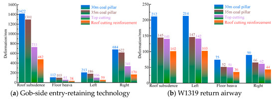
Figure 19.
Deformation statistics of surrounding rocks of the roadway.
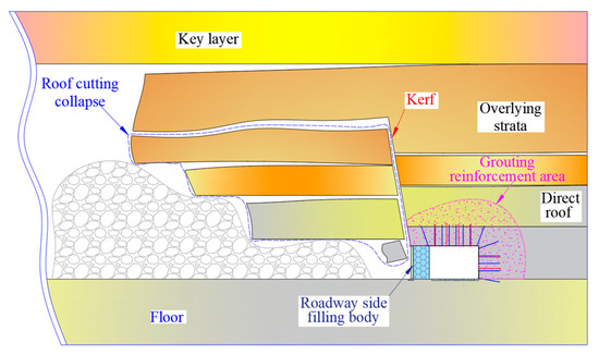
Figure 20.
Deformation statistics of surrounding rocks of the roadway.
Roof cutting is located at the side of the working face. The roof-cutting height and angle are set to 15.3 m and 10°, respectively. Meanwhile, the grouting reinforcement is adopted for the roof and side coal pillars of the gob-side entry-retaining technology. Jin’an Reinforcement I# is selected as the grouting material by deep-shallow hole grouting, with depths of 5 and 2 m, respectively.
On-Site monitoring
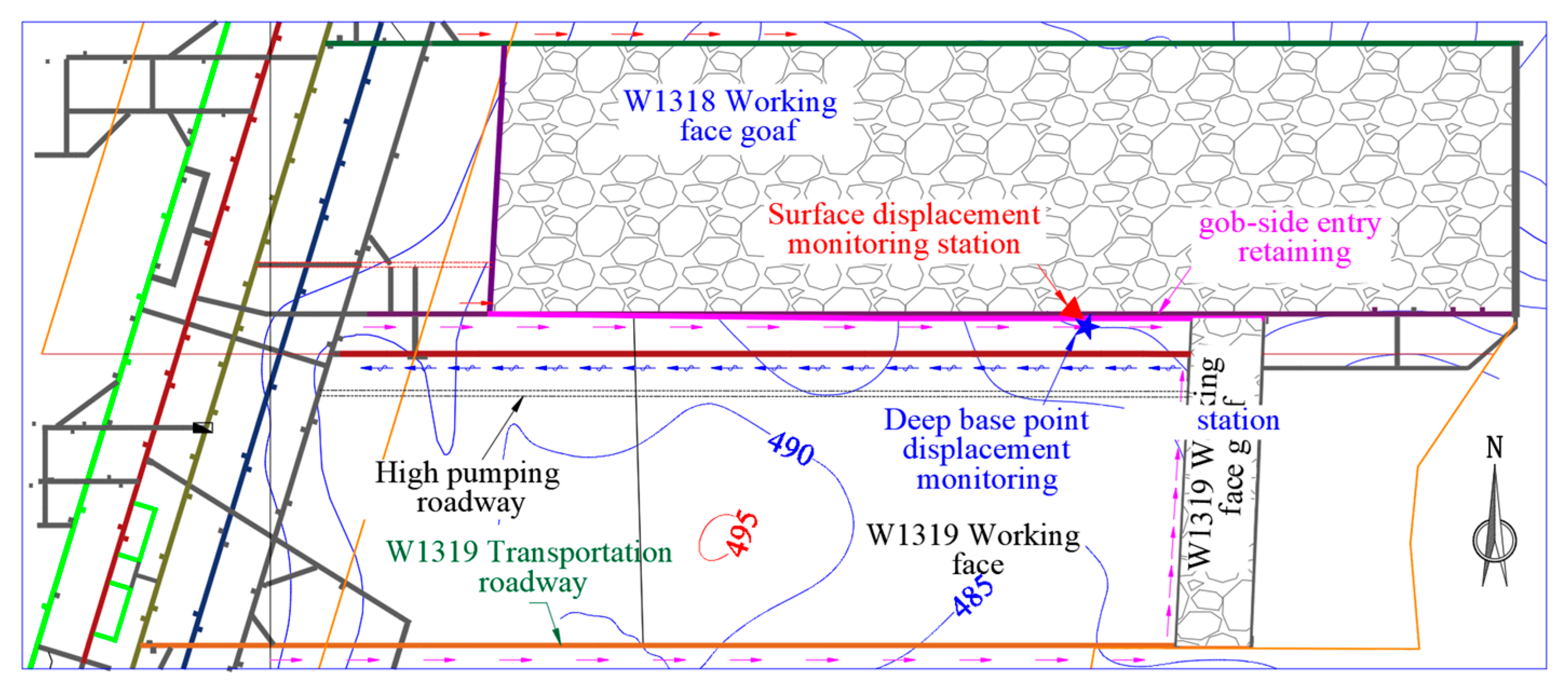
Roof cutting pressure relief and grouting reinforcement are implemented in the stoping process of the W1318 working face. The surface displacement and multi-point displacement monitoring stations are arranged within 100 m in front of the W1319 working face (see Figure 21). Surrounding rock deformations of the roadway are monitored in the stoping process of the working face to determine the surrounding rock failure of the roadway, which verifies the application effect of roof-cutting reinforcement.
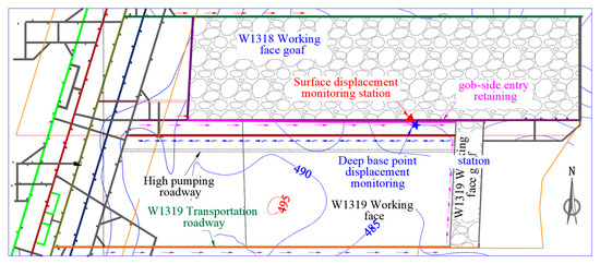
Figure 21.
Position calibration of mine pressure monitoring.
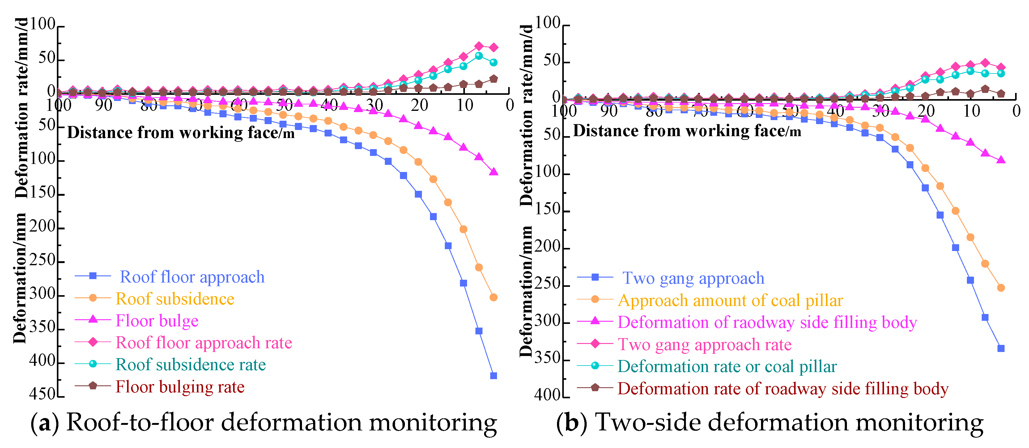
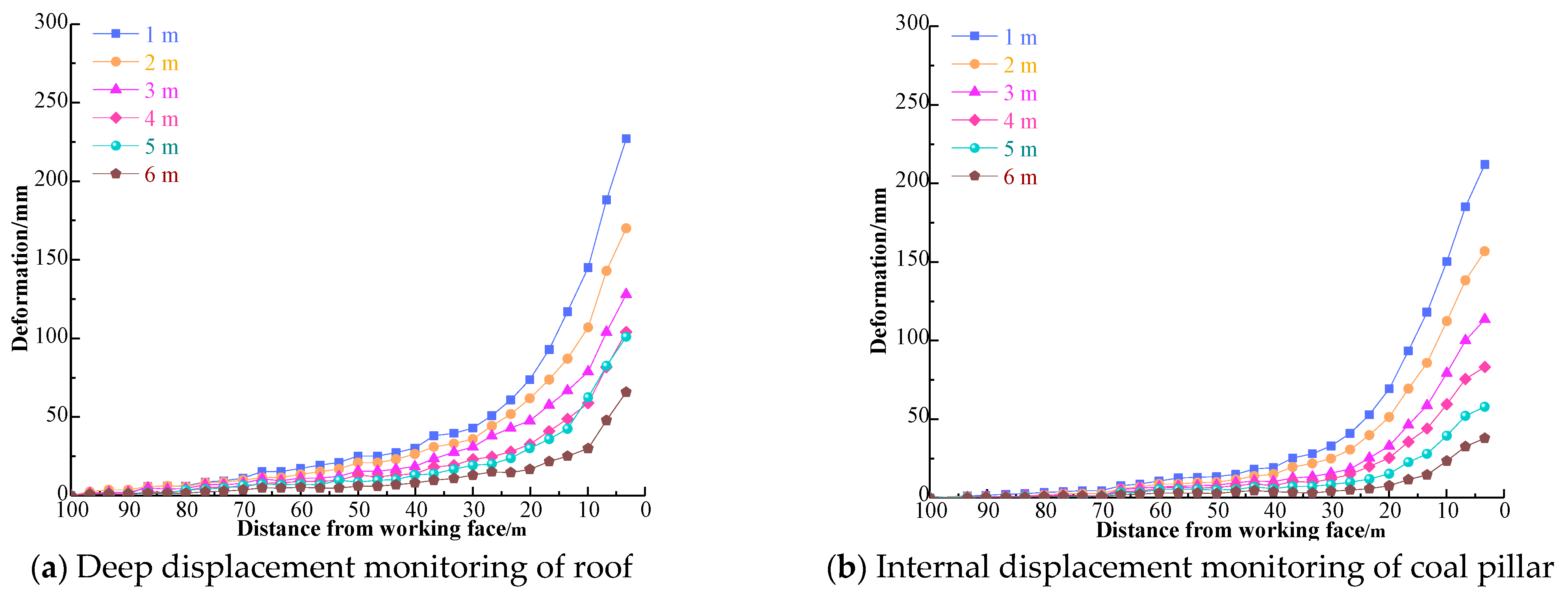
The field measurement results are shown in Figure 22 and Figure 23, When the monitoring station is 40 m away from the working face, the surrounding rocks of the gob-side entry-retaining technology are activated to have severe deformation due to the influence of mining and advanced stress in the mining process of the working face. The deformation rate of the surrounding rocks of the roadway reaches the maximum at about 6 m in front of the working face. The maximum roof-to-floor deformation rate is 71 mm/d; the maximum roof-to-floor approach is 418 mm; the maximum roof subsidence is 302 mm; the maximum two-side approach rate is 44 mm/d. The deformation on the coal-pillar side is much larger than that of the roadside backfill. The maximum two-side approach is 334 mm, and the maximum deformation of the coal pillar side is 253 mm.
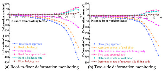
Figure 22.
Monitoring of surrounding-rock deformations of gob-side entry-retaining technology.
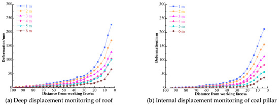
Figure 23.
Deep displacement monitoring of gob-side entry-retaining technology.
Separation layers decrease in the roof and two-side coal rocks with the increased distance from the roadway surface. When the distance between the monitoring station and the working face is less than 40 m, the deep part of the surrounding rocks of the roadway has severe deformations. The maximum deformation in the area within 1 m from the roof is 227 mm; that in the area within 6 m from the roof is 66 mm; that of the roadside in the area within 1 m from the roadway surface is 212 mm; that in the area within 6 m from the roadway surface is 38 mm. The deformation of the deep roadway is consistent with the displacement of the roadway surface. Severe deformations occur in the area within 40 m from the working face. The roadway has certain deformations and global stability in the service period after entry retaining.
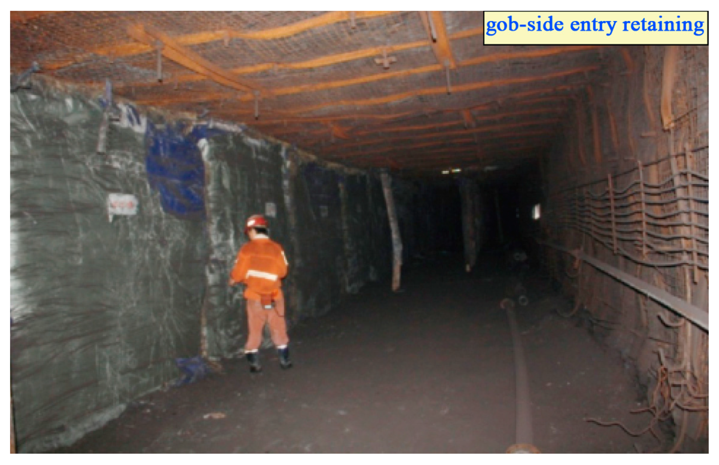
Roadway layout and comprehensive surrounding-rock stability-control technology in soft coal seams without pillar mining in high gas mines studied in the work are applied in the field. The application is shown in Figure 24, The good gas drainage effect of the high-extraction roadway and the prevention of gas accumulation in the stope indicate the reasonable layer selection of high-extraction roadways. The W1319 gob-side entry retaining and W1319 working-face return airway have good surrounding-rock stability during the service period. The work greatly improves the recovery rate of coal resources and realizes the safe and efficient mining of coal pillar-free working faces in soft coal seams in high-gas mines, which prolongs the service life of mines and provides a theoretical basis and scientific reference for similar projects.

Figure 24.
Deep displacement monitoring of gob-side entry-retaining technology.
6. Conclusions
Combined with the geological conditions of coal seams in Gaohe Energy, theoretical analysis, numerical simulation, and on-site measurement were applied to study the roadway layout and entry-retaining control technology for pillar-free mining in high gassy mines.
- (1)
- When high-gas thick-seam coal resources were conducted with pillar-free mining, gob-side entry-retaining technology was used to achieve Y-shaped ventilation in the stoping of the first working face. The gob-side entry-retaining technology of the first working face was adopted to realize W-shaped ventilation in the stoping of the second working face. The gas was extracted by installing high-pumping roadways in the goaf to prevent gas accumulation.
- (2)
- The composite beam theory was combined with Heim’s hydrostatic pressure theory to calculate the stress on the coal pillar. The coal-pillar width was greater than 33.42 m, according to the optimized calculation equation of coal-pillar strength by Bernabeuth-King. The reasonable coal-pillar width was determined to be 35 m by numerical simulation.
- (3)
- According to theoretical calculation and discrete-element numerical simulations, the fracture presented a saddle-shaped development, where the saddle peaks had large heights on both sides; the height of the fracture zone was 38 m in the middle area. Combined with the occurrence of coal seams on-site, the high-pumping roadways of the W1318 working face were arranged in strata that were 35–38 m above the coal seam and 20 m away from the intake airway. Technical measures of roof cutting pressure relief and grouting reinforcement were put forward for controlling the surrounding rocks of the gob-side entry-retaining technology. Combined with the height and fracture development of the on-site caving zone, the height and angle of roof cutting were 15.3 m and 10°, respectively; the grouting method was deep-shallow hole grouting. Surrounding-rock deformations were controlled after the roof-cutting reinforcement.
- (4)
- The entry retaining technology after roof-cutting reinforcement had stable surrounding rocks and controllable deformations in the service period, which met the requirements of safe and stable use. The gas extraction by high-pumping roadways avoided gas accumulation in the goaf. The roadway layout and entry retaining control technology in pillar-free mining has a good on-site application effect, which provides the theoretical basis and scientific reference for similar projects.
Author Contributions
Conceptualization, Q.M. and Y.Z. (Yidong Zhang); methodology, Z.L.; software, Z.L. and Y.Z. (Yu Zheng); validation, G.S. and Q.M.; writing—original draft preparation, Q.M.; writing—review and editing, Y.Z. (Yidong Zhang) and Q.M.; project administration, Y.Z. (Yu Zheng). All authors have read and agreed to the published version of the manuscript.
Funding
The work was funded by the Key Project of Joint Funds of the National Natural Science Foundation of China (Grant No. U1903209).
Institutional Review Board Statement
Not applicable.
Informed Consent Statement
Not applicable.
Data Availability Statement
Not applicable.
Acknowledgments
The authors would like to thank the engineering technicians in Shaping Coal Mine for their enthusiastic assistance and suggestions.
Conflicts of Interest
The authors declare no conflict of interest.
References
- Zhang, T.Z. Current Situation and Development Trend of Energy Utilization in China. Territ. Nat. Resour. Study 2021, 5, 76–78. [Google Scholar]
- Ling, Y.M.; Xu, D.C.; Ju, J.H.; Jiang, W.B.; Deng, G.P. China Mineral Resources; Geological Publishing House: Bejing, China, 2021. [Google Scholar]
- Zheng, C.; Zhang, Y.F.; Long, L.J. Adjustment and Optimization of China’s Main Energy Consumption Structure in the New Era. Coal Geol. China 2021, 33, 49–51. [Google Scholar]
- Hou, C.J. Roadway Surrounding Rock Control; China University of Mining and Technology Press: Xuzhou, China, 2013. [Google Scholar]
- Zhang, H.; Wang, D.X.; Wang, Q.F. Analysis on accident characteristics of Large coal mines in China from 2005 to 2016. J. Saf. Environ. 2019, 15, 1847–1852. [Google Scholar]
- Zhang, J.W.; Yang, H.X. Statistical analysis and safety countermeasures of major and above coal mine accidents in China from 2005 to 2019. Saf. Coal Mines 2021, 52, 261–264. [Google Scholar]
- Xie, X.G.; Huang, C.H.; Yu, Z.Y. Study on safety production situation and countermeasures during the eleventh five-year Plan period of China’s coal mines. Min. Saf. Environ. Prot. 2012, 39, 90–92. [Google Scholar]
- Zhu, Y.F.; Wang, D.M.; Qi, X.Y. Statistical analysis of coal mine Accidents in China from 1950 to 2016. Saf. Coal Mines 2018, 49, 241–244. [Google Scholar]
- Cheng, X.K.; Cai, C.F.; Xiao, Y. Statistical analysis of Coal mine gas accidents in China from 2005 to 2014. Saf. Coal Mines 2016, 47, 224–226, 230. [Google Scholar]
- Guo, Z.T.; Li, J.; Bai, J.B. Study on reasonable width of coal pillar along goaf in fully mechanized Caving mining of extra-thick Coal Seam. Coal Eng. 2022, 54, 19–24. [Google Scholar]
- Guo, J.G.; Li, Y.H.; He, F.L. Study on pillar width and control of fully mechanized Caving along goaf in Extra-thick Coal Seam. Saf. Coal Mines 2021, 52, 190–195. [Google Scholar]
- Lu, S.L. Mine Pressure Appearance of Roadway without Coal Pillar; Coal Industry Press: Beijing, China, 1982. [Google Scholar]
- Li, X.F. Pillar Free Mining; Coal Industry Press: Beijing, China, 1986. [Google Scholar]
- Sun, H.H.; Zhao, B.L. Pillar Free Mining; Coal Industry Press: Beijing, China, 1993. [Google Scholar]
- Ding, K.; Tong, Y.D. Development and Prospect of pillar free Mining in China (I). Coal Eng. 1984, 3, 11–16. [Google Scholar]
- Ding, K.; Tong, Y.D. Development and Prospect of pillar free Mining in China (Ⅱ). Coal Eng. 1984, 4, 1–6. [Google Scholar]
- Kang, H.P.; Zhang, X.; Wang, D.P. Surrounding Rock Control Technology and Application in Pillar-free Mining. J. China Coal Soc. 2022, 47, 29. [Google Scholar]
- Hua, X.Z. Development status and improvement suggestions of goaf retaining support technology in China. Coal Sci. Technol. 2006, 12, 78–81. [Google Scholar]
- He, M.C.; Gao, Y.B.; Yang, J. Study on the coalbolt-free self-generated roadway and its influence on the stress evolution of surrounding rock. Chin. J. Rock Mech. Eng. 2017, 36, 1314–1325. [Google Scholar]
- He, M.C.; Gao, Y.B.; Yang, J. Engineering test of thick coal seam rapid stoping, roof cutting and pressure relief without coal pillar. Rock Soil Mech. 2018, 39, 254–264. [Google Scholar]
- Zhu, Z.; He, M.C.; Wang, Q. A new mining method of automatic roadway formation without pillar in Korshintiaota Coal Mine. J. China Univ. Min. Technol. 2019, 48, 46–53. [Google Scholar]
- Zhang, N.; Han, C.L.; Kan, J.G. Theory and practice of surrounding rock control along goaf retaining roadway. J. China Coal Soc. 2014, 39, 1635–1641. [Google Scholar]
- Zhang, N.; Yuan, L.; Wang, C. Failure characteristics and stability analysis of roof roadway in pressure relief mining. J. China Coal Soc. 2011, 36, 1784–1789. [Google Scholar]
- Chen, Y.; Bai, J.B.; Wang, X.Y. Support technology research and application insideroadway of gob-side entry retaining. J. China Coal Soc. 2012, 37, 903–910. [Google Scholar]
- Yuan, L. Theory and practice of coal pillar-free co-mining in low permeability coal seam group. Strateg. Study CAE 2009, 11, 72–80. [Google Scholar]
- Yuan, L. Research on key technology of safe Mining of Low permeability and High gas Coal seam Group. Chin. J. Rock Mech. Eng. 2008, 7, 1370–1379. [Google Scholar]
- Kang, H.P.; Niu, D.L.; Zhang, Z. Deformation characteristics and supporting technology of surrounding rock of deep goaf retaining roadway. Chin. J. Rock Mech. Eng. 2019, 29, 1977–1987. [Google Scholar]
- Jia, X.R.; Wang, L. Theoretical calculation method of coal pillar critical width in mining roadway. J. Taiyuan Univ. Technol. 2011, 42, 102–103. [Google Scholar]
- Jia, X.R. Rock Mechanics and Strata Control; China University of Mining and Technology Press: Xuzhou, China, 2010. [Google Scholar]
- Bieniawskizt, Z.T.; Sun, H.H. Rock Strata Control in Mining Engineering; China University of Mining and Technology Press: Xuzhou, China, 1990. [Google Scholar]
- Qian, M.G.; Shi, P.W.; Xu, J.L. Mine Pressure and Strata Control; China University of Mining and Technology Press: Xuzhou, China, 2010. [Google Scholar]
- Xu, J.L. Green Mining of Coal Mine; China University of Mining and Technology Press: Xuzhou, China, 2010. [Google Scholar]
- Ministry of Coal Industry. Regulations on Mine Hydrogeology: Trial implementation; Coal Industry Press: Beijing, China, 1984. [Google Scholar]
- Ren, Y.F. Proposal and verification of cantilevered beam-articulated rock beam structure for overburden of shallow buried face. J. China Coal Soc. 2019, 44, 1–8. [Google Scholar]
- Xu, Y.C.; Yang, Y. New progress in water prevention and control technology of floor grouting reinforcement in stope face. Coal Sci. Technol. 2014, 42, 98–102, 120. [Google Scholar]
- Du, X.W. Study on surrounding rock stability and control technology of Gob-side entry retaining in Fully mechanized Caving face of Gaohe Energy. China Univ. Min. Technol. 2019, 2021, 5819672. [Google Scholar]
- Huang, D.F.; Wang, Z.M.; Yang, B. Construction Technology of Water Plugging and Reinforcement by Grouting in Stratum; China University of Mining and Technology Press: Xuzhou, China, 2013. [Google Scholar]
- Wang, P.; Ye, S.F.; Wang, H. Comprehensive grouting reinforcement technology for underground roadway. Saf. Coal Mines 2013, 44, 103–105. [Google Scholar]


Publisher’s Note: MDPI stays neutral with regard to jurisdictional claims in published maps and institutional affiliations. |
© 2022 by the authors. Licensee MDPI, Basel, Switzerland. This article is an open access article distributed under the terms and conditions of the Creative Commons Attribution (CC BY) license (https://creativecommons.org/licenses/by/4.0/).