Article

Characteristics of Bauxite Residue–Limestone Pellets as Feedstock for Fe and Al2O3 Recovery

Department of Materials Science and Engineering, Norwegian University of Science and Technology (NTNU), 7041 Trondheim, Norway
*
Author to whom correspondence should be addressed.
Processes 2023, 11(1), 137; https://doi.org/10.3390/pr11010137
Submission received: 22 November 2022 / Revised: 23 December 2022 / Accepted: 30 December 2022 / Published: 3 January 2023
(This article belongs to the Section Sustainable Processes)

Abstract

:
Experimental research was carried out to produce pellets from bauxite residue for the further extraction of iron and alumina. Bauxite residue and limestone with three different mixture compositions were pelletized experimentally via agglomeration followed by drying and sintering at elevated temperatures. X-Ray diffraction (XRD) and scanning electron microscopy (SEM) were used for the phase and microstructural analysis, respectively. Tumble, abrasion, and breaking load tests were applied to determine the strength of the pellets. For measurement of porosity and surface area, mercury porosimetry and BET surface area methods were applied. It was found that at 1100 °C sintering temperature, all the three sintered pellet compositions have a moderate porosity and low strength, but the reverse result was found when 1200 °C sintering temperature was applied. Moreover, for the pellets sintered at 1150 °C high strength and proper porosities were obtained. In the sintered pellets, iron present in form of brownmillerite (Ca2Fe1.63Al0.36O5), srebrodolskite (Ca2Fe2O5), and fayalite (Fe2SiO4), while alumina present mostly in gehlenite (Ca2Al2SiO7) and little fraction in mayenite (Ca12Al14O33) and brownmillerite phases. The identified phases are the same for of the three pellets, however, with variations in their quantities. Porosity and mechanical properties of pellets are inversely related with both varying sintering temperature and composition. It was found that with more CaCO3 use in pelletizing, higher porosity is obtained. However, with increasing sintering temperature the strength of the pellets increases due to clustering of particles, while porosity decreases.

1. Introduction

Bauxite residue (BR) is a solid waste generated from the Bayer process during alumina production after the significant removal of water from red mud [1,2]. Iron contained in the BR is high and usually around 28 to 54 wt.% depending on the origin of the bauxite ore and the Bayer process parameters [2,3,4]. About 1 to 1.12 tons of BR is generated per ton of alumina produced [5]. More than 168 million tons of BR is generated globally [6], which is a big environmental concern for the aluminum industry because of its large requirement of land for storage and its hazardous nature [3]. It was estimated that the global directory of BR in 2018 exceled above 4.6 billion tons and stockpiled [7]. The residue is hazardous due to its high alkalinity, presence of toxic elements, and very fine particle size, which makes the safe disposal of the residue a big problem. Red mud is stored in huge ponds, which not only occupies large land but also pollutes soil, groundwater, and air [8]. However, BR stockpiling is easier as it does not have potential flood accidents, while landfilling must be done via specific precautions in suitable geographical locations. As BR contains a large percentage of iron, iron recovery from the BR will decrease nearly half the residue’s mass, and a couple of techniques have been studied in the literature [9,10,11] through carbothermic reduction [12]. The valorization of BR through carbothermic reduction with simultaneous slag feedstock production for alumina recovery has been studied through the Ensureal EU project [13]. The carbothermic reduction-based processes have significant carbon footprints and there are concerns about their application in future. Biocarbon use in the BR valorization has been tested successfully in lab and pilot scale in Ensureal to establish a new integrated sustainable process [13].
BR contains iron, aluminum, silicon, calcium, titanium, etc., in different compounds of oxide, hydroxide, carbonate, etc. These are the major contents, and rare earth elements (REEs) usually co-exist as minor valuable elements [14]. Significant research and pilot-scale trials have been carried out in recent years, and still, the commercial utilization of BR in view of material recovery is a major challenge. However, BR is valorized in small amount in cement production, and construction. It can be used to make bricks, tiles, and aggregate blocks for the construction industry, and some patents have been filed [15,16]. The use of BR in these applications is accompanied with the direct loss of valuable materials [4], in particular iron, alumina, and REEs, and indeed its valorization in metallurgical industry is important with regard to circular economy.
A sustainable approach to valorize BR and extract iron, alumina, and REEs has been recently introduced by HARARE EU project, in which an approach to hydrogen reduction of BR agglomerate is carried out to form metallic iron, followed by its magnetic separation and further alumina and REE extraction from the non-magnetic portion. The present research is about the production of feed material for the HARARE process in a so-called Ca-route in which the agglomeration of BR is conducted via mixing with a significant amount of CaO or CaCO3. The addition of lime to BR is based on former research results for Al2O3 recovery from calcium aluminate slags [17] and to stabilize leachable Al2O3-containing phases in the reduced pellets. Azof et al., 2019 found that the leachability order of the calcium aluminate phase from lowest to highest is as follows CaO.Al2O3, 3CaO.Al2O3 and 12CaO.7Al2O3 [17]. When 7 moles of alumina combines with 12 moles of calcium oxide, mayenite is formed (12CaO.7Al2O3), which is an easily leachable phase in Na2CO3 solution to form sodium aluminate and calcium carbonate residue [18,19]. The goal of CaCO3 addition is to form leachable calcium aluminate phases and iron calcium complexes containing as little as possible of the non-leachable gehlenite (Ca2Al2SiO7) phase. In this paper, we focused on the chemical, physical, structural, and mechanical properties of BR–lime pellets based on the limestone fraction and applied sintering temperature.

2. Materials and Methods

2.1. Materials Preparation

BR was provided by the Mytilineos Metallurgy Business Unit S.A., which was previously named Aluminum of Greece, in the form of large and hard lumpy pieces. These were first deagglomerated into a fine powder and dried overnight in an oven at 80 °C. Limestone was received from a paper manufacturing plant in Norway as a waste product, and it was dried for two days in the oven at 80 °C. After the limestone was dried, it was deagglomerated into a fine powder with particle size around the same as BR, below 500 µm.

2.2. Pelletizing and Sintering

The two raw material powders were mixed in three different CaO/Al2O3 ratios equal to 0.85, 1.0, and 1.15 (called hereafter C0.85A, C1A, and C1.15A, respectively) in a ball milling machine at 30 revolutions per minute (rpm) for 90 min to do both mixing and deagglomerate possible remained large BR or limestone clusters. The mixing ratio selection was based on the chemical composition of the two materials and maintained the formation of leachable calcium aluminates in the pellets. Green pellets were produced using a disk pelletizer via water addition. The pelletizing disk speed was 26 ± 2 rotations per minute (rpm) with the disk volume capacity around 130 dm3, and the disc angle was 45 degrees, as experienced to be the optimum angle. The size of the produced green pellets was 4–10 mm, and the pellets were dried in an oven overnight at 80 °C. The overall flow process of pelletization and further high-temperature sintering is shown in Figure 1.
Sintering has two main roles; one is to form some complexes, and the other is to strengthen pellets. Pellet strength has prime importance for the bed permeability; otherwise, it hinders the homogenization of gas flow through the solid bed, which ultimately affects the gas–solid reaction. The dried pellets were subjected to high-temperature sintering in a muffle furnace (Naberthem N17/HR, Bremen, Germany) at three different temperatures (1100 °C, 1150 °C, and 1200 °C) in air. The heating rate of the furnace was 25 °C/min to the desired temperature, 120 min of holding time at the sintering temperature, followed by sample cooling in the furnace. After sintering, the color of the pellets changed from brown to black, as typically shown for increasing temperature for pellet C1A in Figure 2. As shown in Figure 2, there is some clustering of the pellets at C1A-1200 °C sintered pellets with possible partial fusion or formation of semi-molten species. In the C1A-1100 °C- and C1A-1150 °C-sintered pellets, no clustering was observed, while for the latter, the pellets were stronger with no breakage in handling, which was observed for the pellets C1A-1200 °C as well.
In commercial iron ore pelletizing machines such as grate–kiln, the pellets are heated to high temperatures and cooled down in continuous process, and the residence at the elevated temperatures may be shorter than the selected heating profile in this study. However, as the produced pellet compositions in this study are new the chosen temperature profile was to achieve an overview of temperature effect. On the other hand, in the real pelletizing machine there is flow of warm and hot gases through the pellets bed (in different direction) and very complicated than the applied simple sintering in the muffle furnace in this study. An important outcome of this study is, however, that maximum sintering temperature of 1150 °C is proper for BR pellets. Optimizing the proper heating regime and even under gas flows to simulate real pelletizing machine needs dedicated experimental further research.

2.3. Characterization

The mineralogical analysis of materials was carried out by X-Ray diffraction (XRD) technique (Bruker D8 A25 DaVinciTM, Karlsruhe, Germany) with the CuKꭤ radiation in 2θ range from 20 to 70° diffraction angle and step size 0.03 degrees. For the diffraction analysis, the pellets were milled to a fine powder in the ring mill for 45 s at rpm 800. For the phase analysis, a crystallographic database and diffraction EVA software were used. The elemental analysis of the raw materials and produced pellets were conducted using the X-Ray fluorescence (XRF) technique (Thermo Fisher, Degerfors labortorium AB, Sweden). For the microstructural analysis of materials, a scanning electron microscope (SEM) (Zeiss ultra 55LE, Carl Zeiss, Jena, Germany) was used. The chemical elements distribution was evaluated using elemental mapping and energy dispersive spectroscopy (EDS) (Bruker AXS, microanalysis GmbH, Berlin, Germany).
The porosity and pore size distribution of pellets were measured by a mercury intrusion porosimeter (Autopore IV 9520, Micromeritics, USA ) applying high pressures. BET surface area was measured using 3Flex 3500 Chemisorption Analyzer, Micromeritics, USA. Before the sample analysis, the sample was degassed at 250 °C for 10 h to remove the moisture contents of the sintered pellets. To check the strength of the pellets, we used a Compact Hydraulik press, and the cold compression strength of a few single pellets was measured, and the average was calculated. Three measurements for each pellet were carried out to take the average for the calculation of the breaking load. Tumbler and abrasion tests were done as per international standard ISO 3271, 3rd edition [20]. For this test, we used pellets of size greater than 7 mm in diameter in a mini-tumbler test unit in which the standard [20] is rescaled to a smaller size. The dimension of the mini tumbler was an inner diameter of 200 mm, 12 mm in length, and a lifter drum height of 6 mm. The rotation speed of tumbler was 40 rpm for 30 min and 1200 total revolution. The abrasion index was calculated based on the weight fraction of fines below 500 µm divided by the total weight of pellets which is 50 g. The tumble index was calculated as the weight fraction above 5.5 mm pellets divided by the total weight of the pellets taken for the testing. The true density of pellets was measured by a pycnometer (Micromeritics, Accupyc 1340, Pycnometer, USA) with helium gas injection. The calculated true density was based on the total mass divided by the true volume of the sample.

3. Results

3.1. Physical Properties

All the physical properties of the pellets mentioned above are presented and described as follows. The mass loss of all the pellets was in the range of 21 to 23.8% during sintering, as shown in Table 1. The mass loss was more for the more added CaCO3 pellets. With increasing temperature, the weight reduction increases, but there was a smaller weight reduction difference between 1150 °C and 1200 °C.
The BET surface area of dried pellets of C1A is around 16.6 m2/g, while the sintered pellets have a lower surface area. Table 2 shows the BET surface area and porosity of C1A at different sintering temperatures. With increases in sintering temperature, both BET surface area and porosity decrease at fixed composition of C1A.
Table 3 shows the BET Surface area and porosity of pellets sintered at 1150 °C for different compositions. With an increase in CaCO3 in pelletizing at the fixed sintering temperature, both BET surface area and porosity are increased.
For a given pellet composition C1A, it was observed that the sintering temperature rise causes the true density to increase. The density is around 3.53 g/cm3 for 1200 °C and 3.52 g/cm3 for 1150 °C sintered pellets, which is not notable. Standard drop number test was carried out, where green pellets were individually dropped from a 46 cm height on a thick steel plate until the pellets had a breakage or crack appearance on the surface. It was found that drop numbers were the same and in the range of four to five for three different types of green pellets. The wet crushing strength of all three pellet compositions was performed by compression test instrument and found around 0.009–0.01 kN, which were near around compact strength of dry pellets (about 0.01 kN). There was no observation of swelling and no disintegration during the sintering of the pellets, which is shown in Figure 2, which signifies the pellets are not deformed at sintering temperature. Table 4 shows that the breaking load for the sintered pellets increases with increasing the sintering temperature. In addition, an increase in the CaCO3 content of the pellets is accompanied by breaking load decreases.
In a gas–solid reaction, the strength of the pellets bed is very important to have low pellet degradation and abrasion and attain proper gas flow. For C1A-1150 °C, C1A-1200 °C, and C0.85A-1150 °C pellets, the tumble index was above 88%, and the abrasion index was below 6% (see Figure 3), which showed good strength of the pellets for further handling.
The tumbler index is around 80%, and abrasion index is around 10% for C1.15A-1150 °C sintered pellets. It was found in the literature that a tumble index above 92% and an abrasion index below 6% show quite good strength for iron ore pellets for the Midrex process [21]. For C1A-1100 °C, the tumble index is around 54% and abrasion index is around 14%, which signifies this pellet does not have good strength.

3.2. Chemical Analysis

The chemical analysis of the materials with XRF is presented in Table 5. XRF gave the results in the form of elemental analysis, but here we presented the most stable oxide forms of those elements. The XRF results show that the loss of ignition (LOI) was high for limestone sample, as limestone contains CO2 in calcite that is decomposed. The LOI was around 22.5% for dry pellets, and it was below 1% for the sintered pellets. The relative loss weight percentage (wt.%) of oxides is more in the sintered pellets as compared to the dry pellet, which is due to higher LOI in the case of dry pellets, but Na2O content decreases, which indicates that there is some Na2O loss during sintering, probably due to lower vapor pressure than other oxides.

3.3. Phase Analysis (XRD)

XRD analysis result of BR and limestone is shown in Figure 4. Iron is present in the BR in the form of hematite (Fe2O3) and goethite (FeHO2). Titanium is present in the form of anatase (TiO2) and perovskite (CaTiO3). Calcium appears as a calcite (CaCO3) phase in the BR. Aluminum presents as diaspore ꭤ-AlO (OH) and complex phases such as sodalite (Al3Cl1K1Na4O12Si3), cancrinite (C0.76H1.7Al3Ca0.75Na3O14.4Si3), and katoite (AlCa3H9.7O12Si0.69). The XRF analysis in Table 5 shows that hematite present in BR is around 42%, which is the major phase, and alumina is around 22%, which is undigested alumina; hence the quantity of Al-containing phases in the sample regarding XRD results is higher. Calcium in XRF analysis of the limestone is usually reported as CaO. In the limestone sample, the XRD spectrum contains only CaCO3, while in XRF analysis, a small amount of Al2O3, MgO, Fe2O3, SiO2, etc., were measured.
XRD results of three sintered temperatures for pellet C1A are illustrated in Figure 5. It is shown that there are notable phase changes between the sintered pellets and raw materials (Figure 4). Iron is mostly present in the sintered pellets as brownmillerite (Ca2(Fe,Al)2O5), srebrodolskite (Ca2Fe2O5), and fayalite (Fe2SiO4). The main other phases in the sintered pellets are gehlenite (Ca2Al2SiO7), cristobalite (SiO2), perovskite (CaTiO3), lime (CaO), and yeelimite (Al6Ca4O16S). XRD shows some free CaO present in the sintered pellets, while the intensity of free CaO is less for a higher sintering temperature of 1200 °C compared to a lower sintering temperature. The brownmillerite (Ca2(Fe, Al)2O5) phase has the highest amount at 1150 °C sintering temperature.
The XRD spectrums for the C1.15A and C0.85A are presented in Figure 6 and Figure 7, respectively. In both mixtures, the identified phases are almost the same, but the main difference is adding a different amount of CaCO3. The perovskite (CaTiO3) peak appears differently. In the lower CaCO3 addition, the perovskite (CaTiO3) peak intensity is stronger at 1100 °C than 1150 °C, while it again becomes stronger at the higher sintering temperature of 1200 °C (Figure 7). However, for the higher CaCO3 addition, the perovskite (CaTiO3) spectrum is stronger at higher temperatures. Iron-containing phases behave similarly at different sintering temperatures in higher and lower CaCO3 ratios. At 1150 °C, sintering temperature iron-containing phases in all three pellets compositions have a higher intensity of peaks as compared to other sintering temperatures.
From the XRD spectrums in Figure 5, Figure 6 and Figure 7 for all pellets at 1150 °C sintering temperature, it is observed that the iron-containing phases of brownmillerite (Ca2(Fe,Al)2O5), srebrodolskite (Ca2Fe2O5) and fayalite (Fe2SiO4) have higher intensity peaks for C1A. Perovskite (CaTiO3) peak was found to have higher intensity in C1A and C1.15A but the lower intensity at C0.85A.

3.4. Microstructural Analysis

Figure 8 shows the SEM images of sintered pellet C1A at different temperatures. It shows that the sintering of particles is significant at 1200 °C (Figure 8c), which results in more of the pores closing. Sintering at 1100 °C is insignificant (Figure 8a); compared to 1200 °C, while moderate sintering and open porosity have been maintained via sintering at 1150 °C (Figure 8b). The evidence of sintering and semi-molten phase formation at higher temperatures is obvious regarding the changes in porosity distribution and shape and observing less liberated particles at higher temperatures.
Figure 9 shows that in lower C0.85A, too much sintering occurred at 1150 °C, which results in lower open porosity in the pellets compared to 1100 °C (Figure 8). In C1.15A and C1A samples in Figure 9, the microstructures are more similar. At a higher CaCO3 mixture (C1.15A) the porosity is more visible, which agrees with the above porosity measurements. The SEM backscattered images in Figure 9 show that the produced pellets are not homogeneous regarding the chemical composition.
From the scanning electron microscopy (SEM) backscattered detector (QBSD) analysis (Figure 10), it was found that the brightest phases are calcium ferrite (Ca2Fe2O5), calcium aluminoferrite (Ca2(Fe,Al)2O5) and calcium titanate (CaTiO3). However, the CaTiO3 phase appears brighter in the SEM images, with close contrast. We found that Ca2Fe2O5 contains a few percentages of aluminum, such as 6.11 at%, representing Ca2Fe1.44Al0.55O5. The grey phase is the Ca2Al2SiO7 phase, and the outer periphery of the gray phase is sodium aluminate (Figure 10). Silicon is present in two phases in the matrix, one is Ca2Al2SiO7, and another one is Fe2SiO4. As the Fe2SiO4 fraction is low (XRD result), very small areas show the EDS elemental mapping of both Fe, Si, and O. Sodium in the matrix in some areas (Figure 10). Regarding Al, O, and Si co-distribution, it is confirmed that they are found in the form of sodium aluminate and jadeite (AlNaO6Si2) phases, and it is aligned with the XRD analysis above.
The elemental analysis in Figure 10 shows that Ca, Al, and Si are found in a phase together, most likely the Ca2Al2SiO7 phase, considering the XRD results. The elemental mapping at 1150 °C sintered C1.15A pellets shows that in some areas, sodium, and aluminum present with high intensity, but calcium is deficient in those areas (Table 6). Calcium is distributed everywhere in the matrix but is more intense in the iron-containing area.
There are three distinguishable phases based on the contrast in the backscattered imaging. In the pellet, as shown in the Figure 11a; the compositional analysis of area 1 and 3 are the same, but the compositional analysis of area 2 shows that it is a complex mixture of calcium aluminate phase with some fraction of sodium present. The elemental analysis of point 4 shows that it is a complex mixture of sodium aluminate and calcium aluminoferrite.
Brownmillerite (Ca2(Al, Fe)2O5) and srebrodolskite (Ca2Fe2O5) are the iron-containing phases, which are shown in Figure 11b. These are brighter in the BSD analysis of SEM image (Figure 11c,d). Calcium titanate (CaTiO3) and calcium ferrite (Ca2Fe2O5) phases contrast similarly in the SEM image. Figure 11d shows three main phases in the sintered sample. The dark brown phase is the gehlenite (Ca2Al2SiO7) phase, while the calcium ferrite (Ca2Fe2O5) and perovskite (CaTiO3) phases look brighter.

4. Discussion

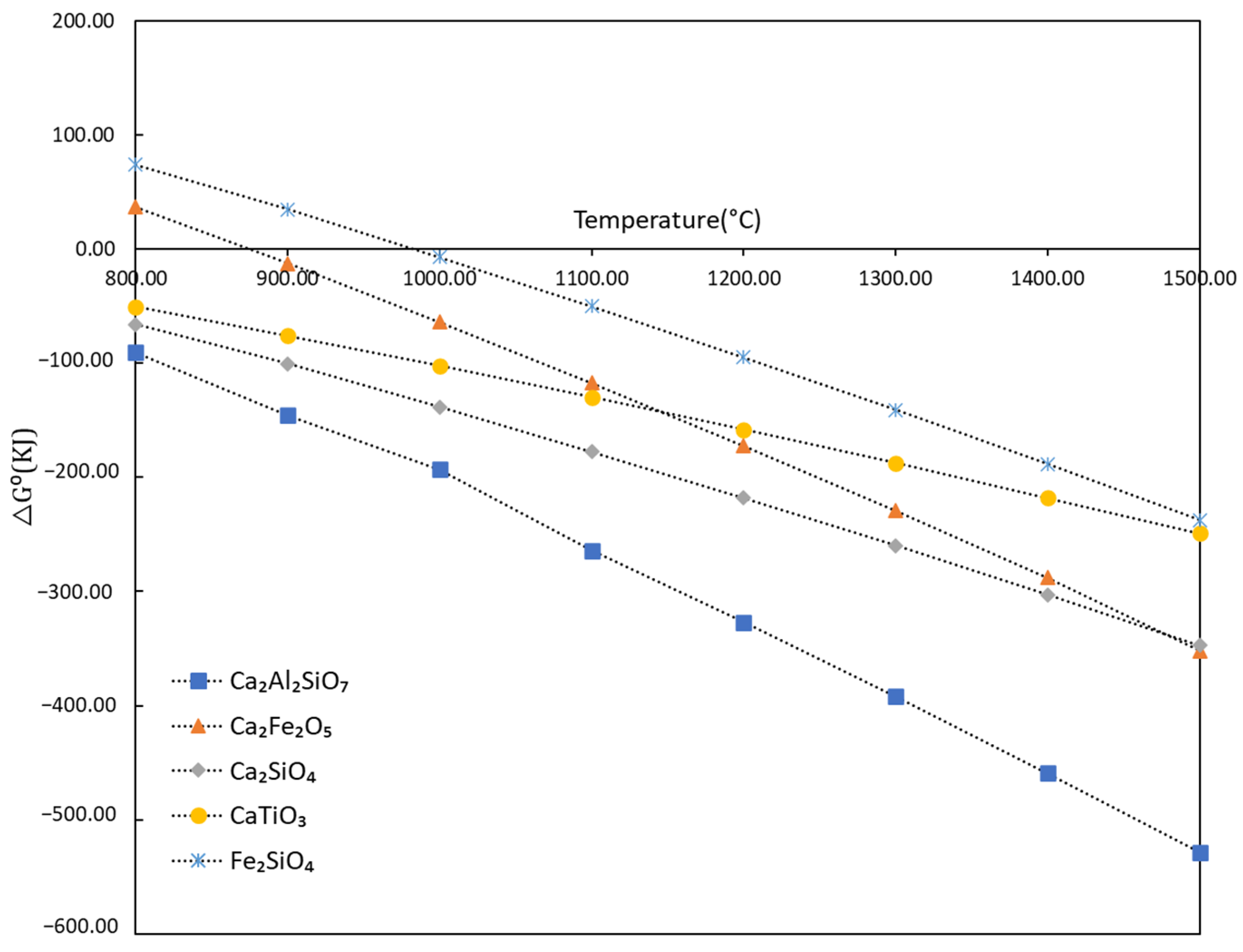
4.1. Evolution of Phases

Based on the XRD and SEM analysis results, the major phases found in the sintered samples are tabulated in Table 7. The melting points found for the stoichiometric phases in the literature are presented. The major phases observed in BR do not exist in the produced pellets, and they have been transformed into other compounds via interaction with the other components of the pellets.
Titanium is present in the BR in TiO2 and minor amount in CaTiO3 phase. During sintering of BR and CaO (that has formed from CaCO3 at lower temperatures) reacts with TiO2 of BR to form CaTiO3:
CaO + TiO 2   CaTiO 3
As shown in Figure 12, the standard free energy of CaTiO3 formation decreases minimally with increasing the sintering temperature.
Gehlenite (Ca2Al2SiO7) is a major peak in all sintered samples, correlated with both XRD and SEM analysis. It is a complex phase of calcium aluminosilicate, formed by two moles of CaO and one mole of Al2O3 and SiO2. The standard free energy of gehlenite formation is relatively lower than other phases, which formed during sintering (Figure 12). With increasing the sintering temperature, the intensity of gehlenite (Ca2Al2SiO7) spectra increases for all different BR and limestone ratio (C0.85A, C1A and C1.15A). As gehlenite is the dominant phase, its formation is most likely through the interaction of Al2O3 (from the decomposed Al hydroxides), SiO2, and CaO via the following reaction:
2 CaO + Al 2 O 3 + SiO 2 Ca 2 Al 2 SiO 7
There is minor amount of Ca12Al14O33 phase found in all sintered samples due to formation of other oxide complexes such as Ca2Al2SiO7, Ca2(Fe,Al)2O5, Al6Ca4O16S.
Fayelite (Fe2SiO4) is the iron silicate phase, it is a moderate/minor phase in sintered samples and regarding the existence of hematite and silica in the raw materials its formation may be shown via the following overall reaction:
Fe 2 O 3 + SiO 2 Fe 2 SiO 4 + 1 2 O 2
Srebrodolskite (Ca2Fe2O5) is a minor Fe-containing phase in all sintered samples. The standard free energy of formation of this phase decreases with sintering temperature rise as shown in Figure 12. During high temperature sintering, iron oxide in the BR reacts with CaO to form calcium ferrite (Ca2Fe2O5) and calcium aluminoferrite (Ca2(Fe,Al)2O5). The Calcium ferrite phase is known as Srebrodolskite (Ca2Fe2O5). However, in X-ray diffraction and SEM-EDX analysis, it was found that in srebrodolskite small amount of Al is present, which can be the reason for observing the XRD peak is a little bit shifted from the standard peak position. The formation of Ca2Fe2O5 phase may be via Formula (4). Furthermore, the formation of Ca2(Fe,Al)2O5 can be via the contribution of Al2O3 directly in the reaction or via later mass transport of Al to Ca2Fe2O5 through the dissolution of Al2O3 into Ca2Fe2O5 or diffusion through solid/semi-solid phases in material.
2 CaO + Fe 2 O 3 Ca 2 Fe 2 O 5
In brownmillerite, there are two atoms of Ca, five atoms of O and the sum of Al and Fe atoms is two, such like Ca2Al0.365Fe1.63 O5. It was found that the intensity of brownmillerite (Ca2Al0.365Fe1.63O5) spectrum decreases at 1200 °C sintering temperature and maximum intensity is found at 1150 °C for a fixed BR and limestone C1A, which may be due to more formation of Ca2Al2SiO7 at 1200 °C. The similar trend is found in both C0.85A and C1.15A. At 1200 °C, in Ca2Al0.55Fe1.44O5, Al atomic fraction increases from 4 to 6.1 at%, which may be due to high temperature atomic diffusion. The chemical reaction for brownmillerite formation may be written as:
6 CaO + 5 2   Fe 2 O 3 + 1 2   Al 2 O 3 + 7 2   O 2 3 ( Ca 2 Fe 1.63 Al 0.36 O 5 )
Yeelimite (Al6Ca4O16S) is a moderate phase which found in all sintered sample. By the reaction of four moles of CaO, three moles of Al2O3 reacts with one mole of SO3 to form Al6Ca4O16S. The SO3 comes from the limestone as it was mentioned.
4 CaO + 3 Al 2 O 3 + SO 3 Al 6 Ca 4 O 16 S
It is worth mentioning that brownmillerite (Ca2Fe1.63Al0.36O5) and yeelimite (Al6Ca4O16S) are currently unavailable in Factsage and other thermodynamical database software and we could not perform the calculations for the formation of these phases.
The observed compounds’ melting points in Table 7 are higher than the applied sintering temperatures in the sintered pellets. Partial melting or softening of compounds normally starts at around 0.6–0.8 Tm, near the sintering temperature of 1200 °C for compounds such as Fe2O3, Ca2Fe2O5, Ca2Al2SiO7, and TiO2. On the other hand, the presented melting points in Table 2 are for the stoichiometric (pure) compounds, while the pellets are not pure and contain impurities; therefore, they have real melting points lower than those in Table 7. Hence, at the applied sintering temperatures, the reactants in Formula (1) to (6) could interact properly within the applied two hours of sintering to yield the products and the formation of the same phases at 1100–1200 °C. The existence of the not significant number of reactants (Al2O3, Fe2O3, CaO, TiO2, SiO2) indicates that they have been consumed completely via the chemical Formula (1) to (6).
In the sintered pellet samples the major fraction of iron and alumina present in brownmillerite (Ca2Fe1.63Al 0.36O5) in addition to iron present in srebrodolskite (Ca2Fe2O5), and fayalite (Fe2SiO4), while alumina is present in gehlenite (Ca2Al2SiO7). After reduction with hydrogen, most of the brownmillerite is converted to metallic iron and mayenite, which was described in our previous work [30]. Alumina can be separated by sodium carbonate leaching of mayenite, and leach residue goes for magnetic separation of iron recovery. Some amount of alumina lost in gehlenite as gehlenite is not leachable phase. In the main approach in the Harare Project, however, Fe separation from the reduced pellets is be performed by magnetic separation and then the alumina recovery from the non-magnetic portion comes via alkaline leaching.

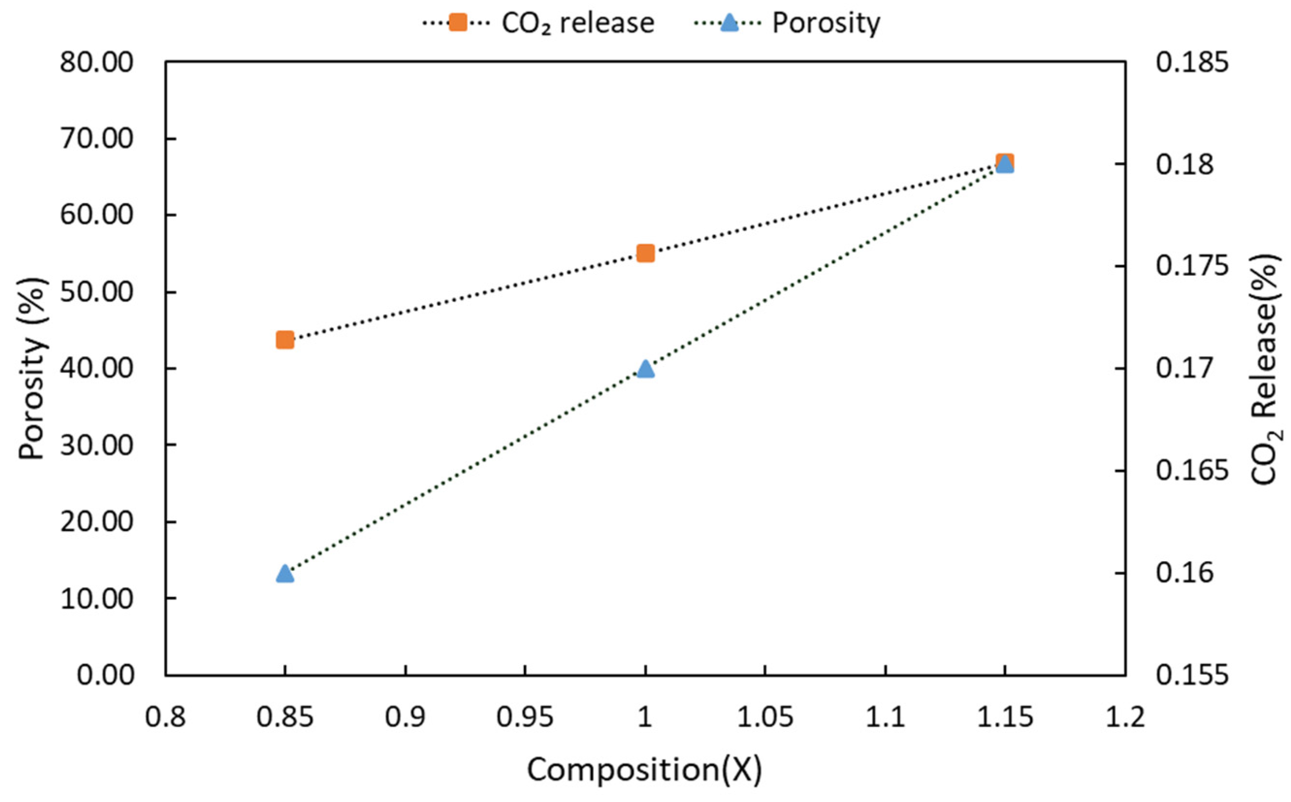
4.2. Physical Properties of Pellets

The higher amount of added calcite causes higher porosity in the pellets. When the sample temperature increases, CaCO3 decomposes to CaO and CO2, and the decomposition temperature is in range of 700–800 °C has been reported [31], while the theoretical decomposition temperature is 887 °C as per HSC version 9.9.2.3. Therefore, the higher weight loss of the samples in sintering when more limestone added is due to the greater CO2 release from the samples.
The mass loss due to calcite decomposition is calculated as 16%, 17%, and 18% for pellets C0.85A, C1A, and C1.15A, respectively. However, the LOI for the C1A-1150 °C is around 22%, so there is 5% difference in the weight loss between calcite decomposition and LOI. It is worth noting that the calcite decomposition weight difference is almost the same at different sintering temperatures for a fixed composition. The 5% weight loss difference between the calcite decomposition and loss of ignition (LOI) may be due to diaspore, gibbsite, and goethite decomposition. Thermal decomposition of the major phase diaspore is between 530 °C to 650 °C [32]. There may be some chemisorbed water that causes weight loss during sintering.
At higher sintering temperatures, the observed slightly higher weight loss is related to some low vapor pressure compounds in BR and limestone, which may vaporize during sintering. XRF results in Table 5 show that the weight percentage of all oxides increases when dry pellets are sintered at 1150 °C except Na2O, indicating a little more weight loss of Na2O during sintering at higher temperatures. There are two compounds of alkali metal oxides that formed after sintering, namely jadeite (AlNaO6Si) and katoite (Al2.1Fe1.9K0.9O12Si2.8). Actually, on the surface of solid particles in BR there is NaOH, which originates from the Bayer process, and yields Na2O in the later sintering process. During sintering, the NaOH on BR particles react with Al2O3 and SiO2 in BR and yields jadeite, which provides strength to the sintered pellets [33]. However, these compounds are present in a very small fraction. These compounds have hardening behaviors, but it was difficult to observe the notable effect of Na2O in the experiments due to its minuscule amount compared to CaO. At high sintering temperature, 1200 °C and above some compounds become softened or semi-molten, usually at 0.6–0.8 Tm of these compounds (Table 7). Therefore, more fusion/sintering occurs, and it causes increase of pellet strength; however, it reduces the porosity of the pellets. As Na2O’s melting point is low (1132 °C) it becomes molten at higher applied temperature and interacts with adjacent oxides (Al2O3 and SiO2) and forms jadeite, as we observed in XRD. The formation of molten Na2O is important because it helps form primary liquid phase and accelerates the migration and recrystallization of solids, a mechanism that may propose is the dissolution of Al2O3 and SiO2 into molten Na2O and the formation of jadeite during the sintering step via mass transport between solid and liquid and even solid to solid regarding the high melting point jadeite (above 1500 °C). This complex oxide formation between the pellets’ particles increases the strength.
BET surface area and porosity of the pellets are largely related to each other, as observed in Table 2. It was found that the porosity of the pellets increases with an increase in limestone addition; however, it decreases with increasing temperature. From the SEM images (Figure 8) we observe significant porosity loss via sintering at 1200 °C compared to the lower temperatures as most of the particles being sintered. Comparing mercury porosimetry and BET surface area, the latter may be more accurate because in BET, we used nitrogen adsorption isotherm, and as nitrogen has a smaller atomic size, it can diffuse more into micropores, which is not possible by pressurized mercury porosimetry.
It is found that the CO2 releases from pellets and porosity evolution for the samples show similar trends at constant sintering temperatures for different BR and limestone ratios as shown in Figure 13. As the limestone amount increases, more CO2 leaves out the sample during sintering, resulting in higher porosity. Hence, we may conclude that porosity evolution correlates with the amount of limestone used and further calcite decomposition. Therefore, it is expected that if quicklime (CaO) is used, the porosity is less dependent on CaO addition compared to CaCO3 addition.

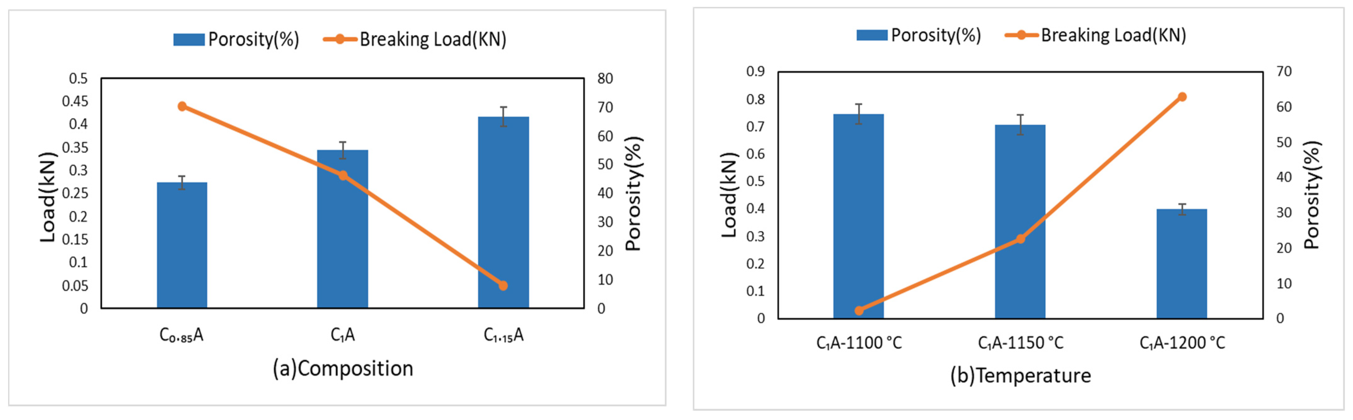
4.3. Mechanical Properties of Pellets

We found that during sintering, the outer surface of the pellets became semi-molten or achieved partial fusion at 1200 °C, causing them to stick to each other. For these pellets, the tumbler index and abrasion index, and breaking load of the pellets were the best. Obviously, the slag-kind phase formation during sintering is accompanied by the formation of stronger bonding between the pellet particles. Moreover, the mechanical properties of pellets depend on the porosity, and lower porosity is directly related to the lower abrasion index. As SEM results indicated, the pellets sintered at 1100 °C did not have many fusion and semi-molten phases.
Figure 14a shows that when the porosity increases the breaking load decreases regarding the composition of pellets. As mentioned above, porosity depends on the sintering temperature and the amount of limestone added. More limestone addition causes higher porosity, which decreases the strength of pellets. Figure 14b indicates that the pellet strength increases for a fixed composition with increasing sintering temperature, but the porosity decreases. This is due to the formation of stronger pellets via more sintering and in parallel porosity loss. In principle, ceramics with higher porosity and lower sintering are weaker in mechanical properties, which is seen here for the pellets sintered at lower temperatures.

5. Conclusions

Experimental work on the pelletizing of bauxite residue and limestone and high temperature sintering was carried out. The effect of lime addition and sintering temperature were studied. The main conclusions are summarized as:
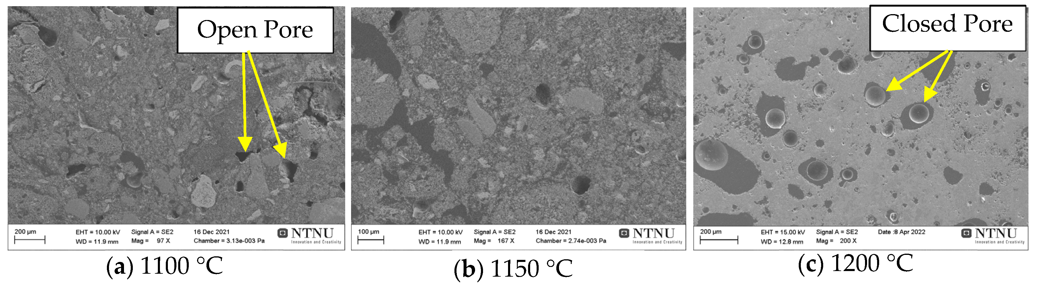
  • Pellet density and weight loss are increased with higher sintering temperature application, which is partly explained by the decrease in BET surface area and porosity; on the other hand, BET surface area and porosity are increased with more CaCO3 addition.
  • It was found that in view of porosity and pellet strength, sintering temperature of 1150 °C yields acceptable pellets with about 90% tumbler index and 55% porosity.
  • Tumble and abrasion indexes are better for the pellets sintered at higher temperatures in range of 1100 °C to 1200 °C and the less CaCO3 added pellets.
  • There is inverse correlation between the strength of the pellets and the porosity, with porosity decreases the strength of pellets is increased, for both varying sintering temperature in range of 1100 °C to 1200 °C and composition of pellets.
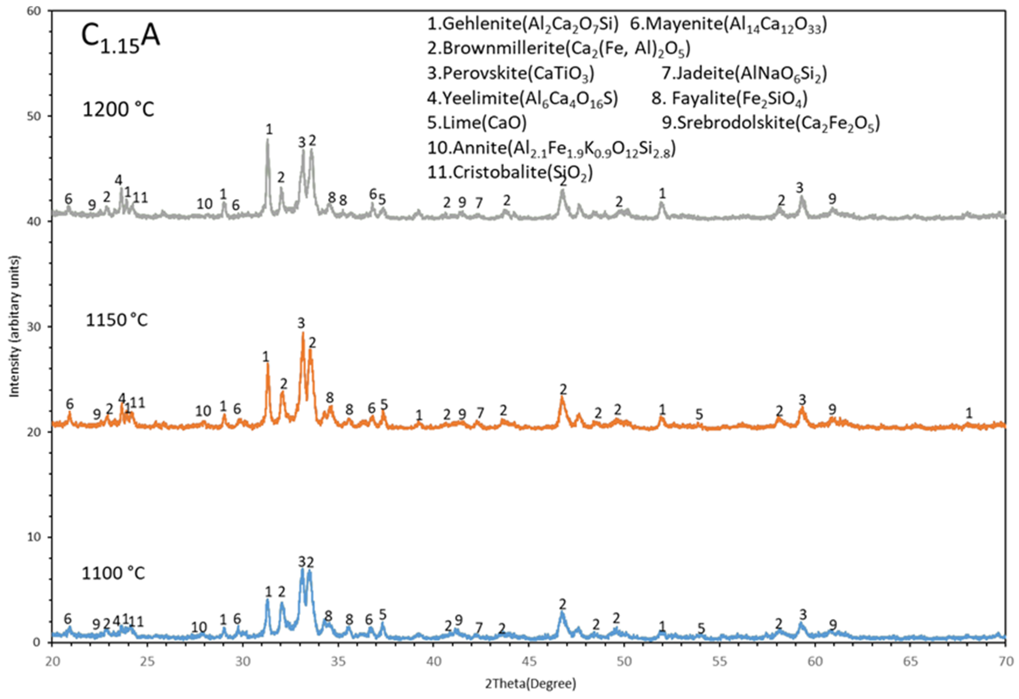
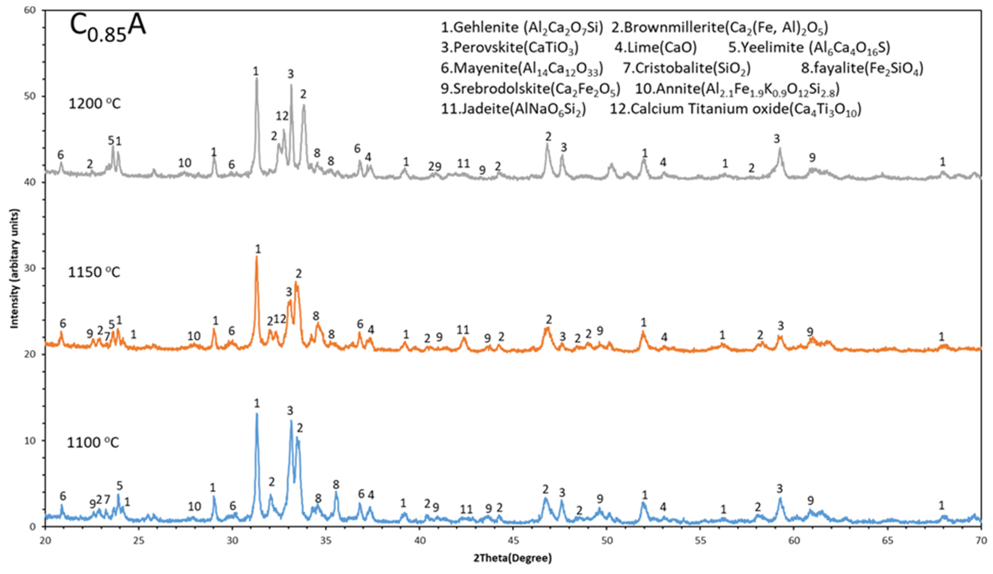
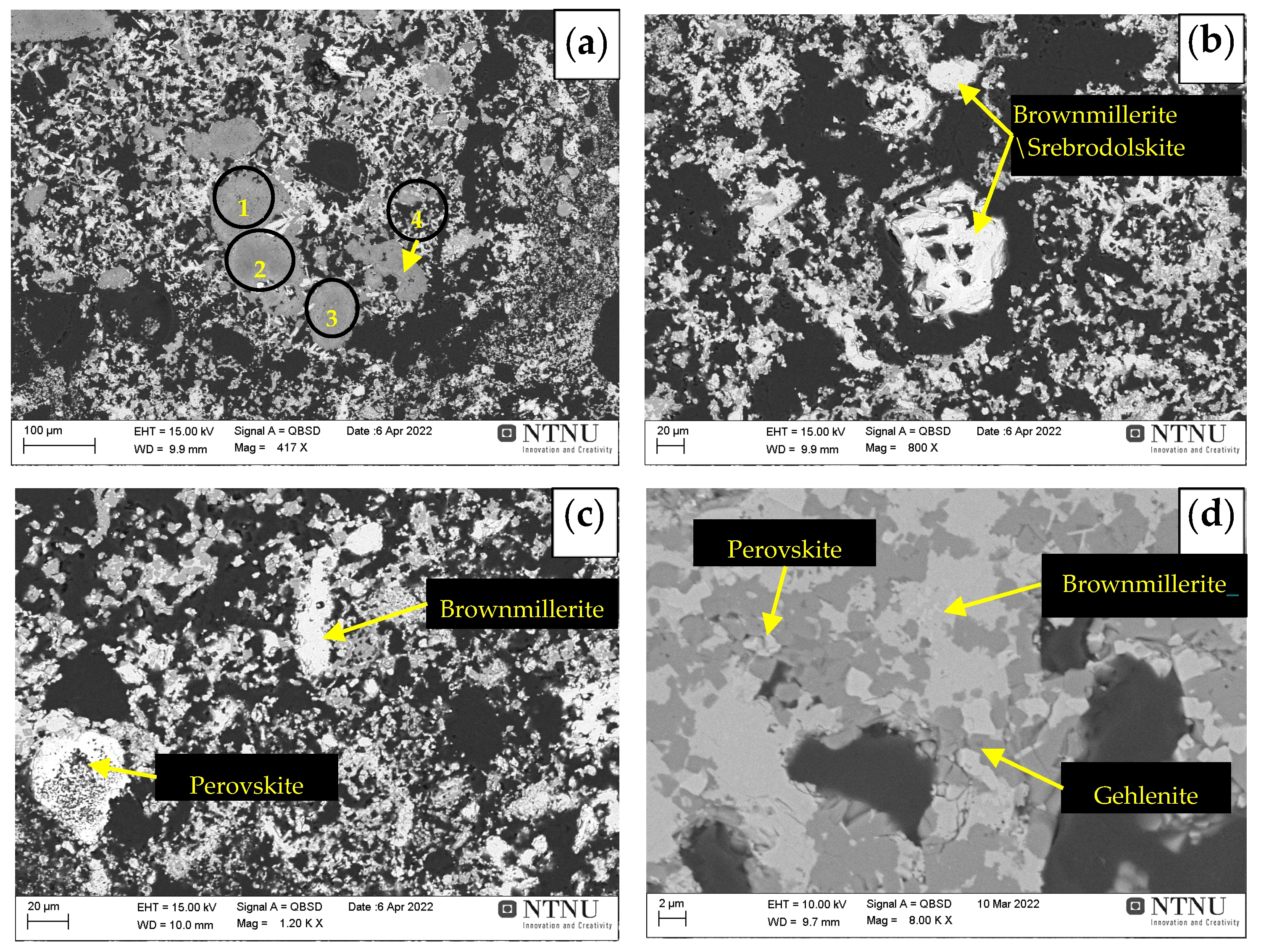
  • Iron present in the sintered pellets mainly in three different phases such as brownmillerite (Ca2(Fe,Al)2O5), srebrodolskite (Ca2Fe2O5), and fayalite (Fe2SiO4). Among these brownmillerite (Ca2(Fe,Al)2O5) is the major iron containing phase.
  • The Al fraction in the Ca2(Fe,Al)2O5 increases with increases in the sintering temperature in range of 1100 °C to 1200 °C, which may be due to more mass transport in sintering via high temperature diffusion.
  • Gehlenite, brownmillerite, and perovskite are the major spectrums in the sintered pellets and gehlenite spectrum becomes more intense with increases in sintering temperature (1100 °C to 1200 °C).

Author Contributions

Conceptualization, M.K.K. and J.S.; methodology, M.K.K. and J.S.; software, M.K.K. and J.S.; validation, M.K.K. and J.S.; formal analysis, M.K.K. and J.S.; investigation, M.K.K.; resources, J.S.; data curation, M.K.K.; writing—original draft preparation, M.K.K.; writing—review and editing, M.K.K. and J.S.; visualization, M.K.K. and J.S.; supervision, J.S.; project administration, M.K.K. and J.S.; funding acquisition, J.S. All authors have read and agreed to the published version of the manuscript.

Funding

This project has received funding from the European Union’s Horizon 2020 research and innovation program under grant agreement 958307.

Data Availability Statement

Not applicable.

Acknowledgments

This project has received funding from the European Union’s Horizon 2020 research and innovation program under grant agreement No. 958307. This publication represents only the authors’ views, exempting the Community from any liability. The Harare Project website is https://h2020harare.eu/ (accessed on 22 November 2022).

Conflicts of Interest

The authors declare no conflict of interest.

References

  1. Balomenos, E.; Panias, D.; Paspaliaris, I. Energy and Exergy Analysis of the Primary Aluminum Production Processes: A Review on Current and Future Sustainability. Miner. Process. Extr. Metall. Rev. 2011, 32, 69–89. [Google Scholar] [CrossRef]
  2. Borra, C.R.; Blanpain, B.; Pontikes, Y.; Binnemans, K.; Van Gerven, T. Recovery of Rare Earths and Other Valuable Metals from Bauxite Residue (Red Mud): A Review. J. Sustain. Metall. 2016, 2, 365–386. [Google Scholar] [CrossRef] [Green Version]
  3. Evans, K. The History, Challenges, and New Developments in the Management and Use of Bauxite Residue. J. Sustain. Metall. 2016, 2, 316–331. [Google Scholar] [CrossRef] [Green Version]
  4. Safarian, J.; Kolbeinsen, L. Sustainability in Alumina Production from Bauxite. Sustain. Ind. Process. Summit 2016, 5, 75–82. [Google Scholar]
  5. Kumar, S.; Kumar, R.; Bandopadhyay, A. Innovative Methodologies for the Utilisation of Wastes from Metallurgical and Allied Industries. Resour. Conserv. Recycl. 2006, 48, 301–314. [Google Scholar] [CrossRef]
  6. Wang, M.; Liu, X. Applications of Red Mud as an Environmental Remediation Material: A Review. J. Hazard. Mater. 2021, 408, 124420. [Google Scholar] [CrossRef]
  7. Lyu, F.; Hu, Y.; Wang, L.; Sun, W. Dealkalization Processes of Bauxite Residue: A Comprehensive Review. J. Hazard. Mater. 2021, 403, 123671. [Google Scholar] [CrossRef]
  8. Power, G.; Gräfe, M.; Klauber, C. Bauxite Residue Issues: I. Current Management, Disposal and Storage Practices. Hydrometallurgy 2011, 108, 33–45. [Google Scholar] [CrossRef]
  9. Cardenia, C.; Xakalashe, B.; Balomenos, E.; Panias, D.; Friedrich, B. Reductive roasting process for the recovery of iron oxides from bauxite residue through rotary kiln furnace and magnetic separation. In Proceedings of the 35th International ICSOBA Conference, Hamburg, Germany, 2–5 October 2017; pp. 2–5. [Google Scholar]
  10. Yin, P.T.; Buhle Xakalashe, B.F.; Panias, D.; Vassiliadou, V. Carbothermic reduction of bauxite residue for iron recovery and subsequent aluminium recovery from slag leaching. In Proceedings of the 35th International ICSOBA Conference, Hamburg, Germany, 2–5 October 2017; pp. 603–613. [Google Scholar]
  11. Archambo, M.S.; Kawatra, S.K. Utilization of Bauxite Residue: Recovering Iron Values Using the Iron Nugget Process. Miner. Process. Extr. Metall. Rev. 2021, 42, 222–230. [Google Scholar] [CrossRef]
  12. Lazou, A.; Van Der Eijk, C.; Tang, K.; Balomenos, E.; Kolbeinsen, L.; Safarian, J. The Utilization of Bauxite Residue with a Calcite-Rich Bauxite Ore in the Pedersen Process for Iron and Alumina Extraction. Metall. Mater. Trans. B 2021, 52, 1255–1266. [Google Scholar] [CrossRef]
  13. Lazou, A.; Van der Eijk, C.; Balomenos, E.; Safarian, J. Smelting Reduction of Bauxite Residue and Beneficiation By-Product in View of a Leachable Slag and Pig Iron Production. In Proceedings of the European Metallurgical Conference, Düsseldorf, Germany, 23–26 June 2019; pp. 17–34. [Google Scholar]
  14. Gräfe, M.; Power, G.; Klauber, C. Bauxite Residue Issues: III. Alkalinity and Associated Chemistry. Hydrometallurgy 2011, 108, 60–79. [Google Scholar] [CrossRef]
  15. Wagner, G.H. Making Concrete Articles and the Like; 1932. Available online: https://patents.google.com/patent/US1865732A/en (accessed on 22 November 2022).
  16. Jaquays, C. Building and Other Materials Containing Treated Bauxite Tailings and Process for Making Same. U.S. Patent 20050087107, 28 April 2005. [Google Scholar]
  17. Azof, F.I.; Yang, Y.; Panias, D.; Kolbeinsen, L.; Safarian, J. Leaching Characteristics and Mechanism of the Synthetic Calcium-Aluminate Slags for Alumina Recovery. Hydrometallurgy 2019, 185, 273–290. [Google Scholar] [CrossRef]
  18. Blake, H.E. Adaptation of the Pedersen Process to the Ferruginous Bauxites of the Pacific Northwest; U.S. Department of the Interior, Bureau of Mines: Washington, DC, USA, 1967; p. 6939. [Google Scholar]
  19. Azof, F.I.; Safarian, J.; Kolbeinsen, L. The leachability of calcium aluminate phases in slags for the extraction of alumina. In Proceedings of the 35th International ICSOBA Conference, Hamburg, Germany, 2–5 October 2017. [Google Scholar]
  20. ISO 3271; Iron Ores for Blast Furnace and Direct Reduction Feedstocks–Determination of the Tumble and Abrasion Indices. ISO: Geneva, Switzerland, 1995.
  21. Monsen, B.E.; Thomassen, E.S.; Bragstad, I.; Ringdalen, E.; Hoegaas, P.H. Characterization of DR pellets for DRI applications. In Proceedings of the Association for Iron and Steel Technology Conference Proceedings, Cleveland, OH, USA, 4–7 May 2015. [Google Scholar]
  22. Qu, Y.; Yang, Y.; Zou, Z.; Zeilstra, C.; Meijer, K.; Boom, R. Melting and Reduction Behaviour of Individual Fine Hematite Ore Particles. ISIJ Int. 2015, 55, 149–157. [Google Scholar] [CrossRef] [Green Version]
  23. Li, Y.; Ishigaki, T. Thermodynamic Analysis of Nucleation of Anatase and Rutile from TiO2 Melt. J. Cryst. Growth 2002, 242, 511–516. [Google Scholar] [CrossRef]
  24. Poirier, J. 1P Lindemann Law and the Melting Temperature of Perovskites. Phys. Earth Planet. Inter. 1989, 54, 364–369. [Google Scholar] [CrossRef]
  25. Charlu, T.V.; Newton, R.C.; Kleppa, O.J. Thermochemistry of Synthetic Ca2Al2SiO7 (Gehlenite)-Ca2MgSi2O7 (Åkermanite) Melilites. Geochim. Cosmochim. Acta 1981, 45, 1609–1617. [Google Scholar] [CrossRef]
  26. Jackson, W.E.; De Leon, J.M.; Brown, G.E., Jr.; Waychunas, G.A.; Conradson, S.D.; Combes, J.-M. High-Temperature XAS Study of Fe2SiO4 Liquid: Reduced Coordination of Ferrous Iron. Science 1993, 262, 229–233. [Google Scholar] [CrossRef]
  27. Luna Vera, F.; Guancha Chalapud, M.; Castillo Viveros, I.; Vásquez Medina, E.A. From Eggshells to Quicklime: Using Carbonate Cycle as an Integrating Concept to Introduce Students to Materials Analysis by TGA and FTIR. J. Chem. Educ. 2018, 95, 625–630. [Google Scholar] [CrossRef]
  28. Tolkacheva, A.S.; Shkerin, S.N.; Korzun, I.V.; Plaksin, S.V.; Khrustov, V.R.; Ordinartsev, D.P. Phase Transition in Mayenite Ca12Al14O33. Russ. J. Inorg. Chem. 2012, 57, 1014–1018. [Google Scholar] [CrossRef]
  29. Ceretti, M.; Corallini, S.; Paulus, W. Influence of Phase Transformations on Crystal Growth of Stoichiometric Brownmillerite Oxides: Sr2ScGaO5 and Ca2Fe2O5. Crystals 2016, 6, 146. [Google Scholar] [CrossRef] [Green Version]
  30. Kar, M.K.; Van Der Eijk, C.; Safarian, J. Hydrogen reduction of high temperature sintered and self-hardened pellets of bauxite residue produced via the addition of limestone and quicklime. In Proceedings of the 40th International ICSOBA Conference, Athens, Greece, 10–14 October 2022; p. 11. [Google Scholar]
  31. Karunadasa, K.S.P.; Manoratne, C.H.; Pitawala, H.; Rajapakse, R.M.G. Thermal Decomposition of Calcium Carbonate (Calcite Polymorph) as Examined by in-Situ High-Temperature X-Ray Powder Diffraction. J. Phys. Chem. Solids 2019, 134, 21–28. [Google Scholar] [CrossRef]
  32. Kloprogge, J.T.; Ruan, H.D.; Frost, R.L. Thermal Decomposition of Bauxite Minerals: Infrared Emission Spectroscopy of Gibbsite, Boehmite and Diaspore. J. Mater. Sci. 2002, 37, 1121–1129. [Google Scholar] [CrossRef] [Green Version]
  33. Jamil, N.H.; Abdullah, M.M.A.B.; Ibrahim, W.M.A.W.; Rahim, R.; Sandu, A.V.; Vizureanu, P.; Castro-Gomes, J.; Gómez-Soberón, J.M. Effect of Sintering Parameters on Microstructural Evolution of Low Sintered Geopolymer Based on Kaolin and Ground-Granulated Blast-Furnace Slag. Crystals 2022, 12, 1553. [Google Scholar] [CrossRef]
Figure 1. Overall pelletization and sintering process.
Processes 11 00137 g001
Figure 2. Sintered oxide pellets at different temperatures for C1A.
Processes 11 00137 g002
Figure 3. Tumble and abrasion indexes of sintered pellets.
Processes 11 00137 g003
Figure 4. XRD patterns of the bauxite residue and limestone with the identified phases.
Processes 11 00137 g004
Figure 5. XRD patterns of the C1A oxide pellets at different sintering temperatures.
Processes 11 00137 g005
Figure 6. XRD patterns of the C1.15A oxide pellets at different sintering temperatures.
Processes 11 00137 g006
Figure 7. XRD patterns of the C0.85A oxide pellets at different sintering temperatures.
Processes 11 00137 g007
Figure 8. SEM secondary electron image of C1A ratio pellets with three different sintering temperatures (a) 1100 °C, (b) 1150 °C, (c) 1200 °C.
Processes 11 00137 g008
Figure 9. SEM backscattered electron images of three different pellet compositions sintered at 1150 °C (a) C0.85A, (b) C1A, (c) C1.15A.
Processes 11 00137 g009
Figure 10. EDS elemental mapping of C1.15A sintered at 1150 °C.
Processes 11 00137 g010
Figure 11. SEM images of C1.15A-1150 °C (ac) and C0.85A-1150 °C (d), and the identified phases.
Processes 11 00137 g011
Figure 12. Standard free energy of formation, △G° (J/mol at 1 atm), for one mole of different phases at elevated temperatures. Calculated using Factsage 8.1 software.
Processes 11 00137 g012
Figure 13. Released CO2 gas and measured porosity for pellets with composition (CxA) at 1150 °C sintering temperature.
Processes 11 00137 g013
Figure 14. Porosity vs. breaking load of different compositions at fixed sintering temperature 1150 °C (a), and at different temperatures for fixed composition C1A (b).
Processes 11 00137 g014
Table 1. Weight reductions (wt.%) at different applied sintering temperatures.
Composition/Temperature (°C)1100 °C1150 °C1200 °C
C0.85A21.421.621.8
C1A21.521.821.9
C1.15A23.123.723.8
Table 2. BET surface area and porosity of different sintering temperatures for C1A.
Temperature (°C)BET Surface Area (m2/g)Porosity (vol%)
11001.0658.85
11500.2954.99
12000.2531.45
Table 3. BET surface area and porosity of different composition (CXA) pellets at 1150 °C sintering.
Composition (CxA)BET Surface Area (m2/g)Porosity (vol%)
C0.85A0.2543.35
C1A0.2954.99
C1.15A0.3966.78
Table 4. Breaking load of different sintering temperature with different pellets composition. (All measurements in kN, SD: standard deviation).
Ratio/Temperature1100 °C1150°C1200°C
C1.15A0.01330.050.5
SD0.010.010.1
C1A0.03660.29330.8166
SD0.010.080.8
C0.85A0.07330.44661.266
SD0.020.040.08
Table 5. Chemical composition of different materials measured by XRF (wt.%).
Samples/OxidesAl2O3CaOFe2O3K2OMnOMgONa2OP2O5SO3SiO2TiO2Cr2O3V2O5NiOLOI
BR22.008.8041.710.090.080.233.100.110.956.105.0011.83
Limestone0.9052.700.150.120.950.010.062.070.0342.60
BR + CaCO3
(Dry pellets)
13.2027.5023.200.150.040.592.550.070.586.053.250.140.110.0722.40
Sintered
(C1A-1150 °C)
19.8032.8029.600.190.050.512.310.120.968.304.070.200.150.100.72
Table 6. EDS elemental analysis of different areas and points of Figure 11a.
ElementsArea 1Area 2Area 3Point 4
Al35.041.135.531.7
O42.143.843.137.9
Fe5.31.43.24.5
Ca7.15.67.97.7
Na9.36.79.014.2
Table 7. The identified phases in the produced pellets at different compositions/temperatures, sorted based on their XRD spectrum intensity and SEM image analysis.
CompoundsBRC0.85A-1150 °CC1A-1150 °C C1.15A-1150 °C C1A-1100 °CC1A-1200 °CMelting Points
Fe2O3 (hematite)Major XRD1565 °C [22]
AlOOH (diaspore)Major XRD
TiO2 (anatase)Major XRD1784 °C [23]
CaTiO3 (perovskite)Minor XRDMajor XRD, SEMMajor XRD, SEMMajor XRD, SEMMajor XRD, SEMMajor XRD, SEM1975 °C [24]
Ca2Al2SiO7 (gehlenite)Major XRD and SEMMajor XRD and SEMMajor XRD and SEMMajor XRD and SEMMajor XRD and SEM1593 °C [25]
Ca2(Al,Fe)2O5 (brownmillerite)Major XRD and SEMMajor XRD and SEMMajor XRD and SEMMajor XRD and SEMMajor XRD and SEM
Fe2SiO4 (fayelite)Moderate XRDModerate
XRD
Minor XRDModerate XRD Minor XRD1204 °C [26]
CaO (calcium oxide)Moderate XRD and SEMModerate XRD and SEMModerate XRD and SEMModerate XRD and SEMMinor in XRD and SEM2572 °C [27]
Al6Ca4O16S (yellimite)Moderate XRDModerate
XRD
Moderate
XRD
Moderate
XRD
Moderate
XRD
12CaO.7Al2O3 (mayenite) Minor XRDMinor XRDMinor XRDMinor XRDMinor XRD1373 °C [28]
Ca2Fe2O5 (srebrodolskite)Minor XRD and SEMMinor XRD and SEMMinor in XRD and SEMMinor in XRD and SEMMinor in XRD and SEM1350 °C [29]
Disclaimer/Publisher’s Note: The statements, opinions and data contained in all publications are solely those of the individual author(s) and contributor(s) and not of MDPI and/or the editor(s). MDPI and/or the editor(s) disclaim responsibility for any injury to people or property resulting from any ideas, methods, instructions or products referred to in the content.

