Article

Design and Dynamic Characteristics Analysis of Novel Support Adjustment Mechanism of Wheeled Downhole Tractor

1
School of Mechatronic Engineering, Southwest Petroleum University, Chengdu 610500, China
2
School of Mechanical Engineering, Sichuan University of Science & Engineering, Yibin 644005, China
3
Sichuan Guangtai Construction Project Management Co., Ltd., Nanchong 637003, China
4
State Key Laboratory of Oil and Gas Reservoir Geology and Exploitation, Chengdu University of Technology, Chengdu 610059, China
*
Author to whom correspondence should be addressed.
Processes 2023, 11(1), 140; https://doi.org/10.3390/pr11010140
Submission received: 1 December 2022 / Revised: 24 December 2022 / Accepted: 27 December 2022 / Published: 3 January 2023
(This article belongs to the Special Issue New Research on Oil and Gas Equipment and Technology)

Abstract

:
Conventional design method of the downhole tractor is based on cementing casing, which is only suitable for the smooth wellbore. For the open hole well, the conventional downhole tractor has poor adaptability and even cannot work normally. In order to improve the obstacle surmounting performance of the wheeled downhole tractor (WDR) and expand the application range of the WDR, a double push rod-double spring support adjustment mechanism (DPRDSSAM) is proposed in this paper. Meanwhile, the proposed DPRDSSAM also needs to increase the traction force and the stability of the WDR in the open hole well. Kinematic simulation numerical models of both conventional support adjustment mechanism and the DPRDSSAM are established. The two models comprehensively considere the influence of different obstacle forms and sizes on the obstacle surmounting performance of the tractor. The influence of different obstacle forms on the obstacle surmounting performance of DPRDSSAM and single push rod support adjustment mechanism (SPRSAM) is analyzed. Results show that the DPRDSSAM has better obstacle surmounting performance than the SPRSAM. The DPRDSSAM can effectively promote further research and application of the tractor in the open hole well.

1. Introduction

The horizontal well is the main well type in downhole engneeing. The horizontal well technology has become an important technique in oil recovery [1,2,3,4,5]. Downhole operations (such as logging) are usually faced with the challenge of instrument transportation. The downhole tractor can solve the problem of downhole instrument transportation. Commonly used downhole tractors are divided into the wheeled downhole tractor (WDR) and the telescopic downhole tractor. The telescopic downhole tractor provides greater traction, but the speed is slow. On the contrary, the WDR provides small traction and faster speed [6]. In terms of well logging, as time is very tense, the traction instrument for logging is light in weight, and the WDR with high speed is mainly used [7,8,9]. It is simple and fast to use the WDR to transport instruments in the horizontal well [10]. However, at present, the tractive force of the WDR is small, and the requirements for wellbore quality are high. Because the conventional WDR is not suitable for the open hole well, the instrument transportation for the open hole well is faced with major technical probems [11]. The adaptability of the WDR is poor. The WDR moves in the casing pipe. During the use of the casing pipe, defects, such as well wall deposit, casing wear, and casing reduction, are caused on the inner wall [12,13]. Therefore, the propping wheel may move on the irregular inner wall of the casing pipe. If the propping wheel cannot cross through obstacles, the WDR may be seized, affecting normal operations, and even resulting in downhole accidents. Therefore, the industry places higher demands on the obstacle surmounting the performance of the existing WDR [14,15]. The WDR is essentially composed of the transmission mechanism and the support adjustment mechanism. The transmission mechanism drives the propping wheel to rotate. The support adjustment mechanism regulates the radial position of the propping wheel so that the propping wheel contacts with the casing pipe or disengages from the casing pipe. The propping wheel contacts the casing pipe under the action of the support adjust ment mechanism so that the WDR can move forward in the casing pipe. The support adjustment mechanisms of the existing WDR mainly include the piston and rod support adjustment mechanism, the motor and slider support adjustment mechanism, the cam support adjustment mechanism, the skid rod support adjustment mechanism, and the slider and chute support adjustment mechanism. For the piston and rod support adjustment mechanism, it is difficult to adjust the support arm. The WDR with the piston and rod support adjustment mechanism has a poor obstacle surmounting performance. The structure of the motor and slider support adjustment mechanism is simple. The motor and slider support adjustment mechanism only has an adjustment spring. Therefore, the propping wheel operates with difficulty under complex casing obstacles. The structure of the cam support adjustment mechanism is complex. One cam controls two propping wheels. The WDR with the cam support adjustment mechanism is prone to inconsistent movements when crossing different obstacles simultaneously. The cam support adjustment mechanism has a poor obstacle surmounting performance. The skid rod support adjustment mechanism contains three or more support wheels. The skid rod support adjustment mechanism can produce greater traction than conventional support adjustment mechanisms. The WDR with the slider and chute support adjustment mechanism has an excellent efficiency of transmission. The slider and chute support adjustment mechanism operates more stably. However, the slider and chute support adjustment mechanism does not accommodate multiple casing obstacles [16,17,18,19]. Therefore, the above support adjustment mechanisms cannot meet the requirements of the downhole complex environment and the working of domestic horizontal wells when dealing with various impurities and obstacles in the casing pipe. For the support adjustment mechanism, it is necessary to improve the traction and the stability of the WDR.
Based on this condition, this paper proposed a double push rod-double spring support adjustment mechanism (DPRDSSAM) with excellent obstacle surmounting performance. The proposed DPRDSSAM can improve the adaptability of the WDR. The obstacle surmounting performance of the support adjustment mechanism of the WDR was studied with kinematics software. Relevant performance between the existing single push rod support adjustment mechanism (SPRSAM) and the designed DPRDSSAM in the obstacle surmounting process was contrasted and analyzed. Thus providing the basis for the optimization design of the support adjustment mechanism of the WDR.

2. Structure Design of DPRDSSAM

In this paper, according to performance parameters and characteristics of the WDR, a new support adjustment mechanism was designed which is DPRDSSAM. The overall structure of the WDR with the SPRSAM is similar to that of the WDR with DPRDSSAM. The overall structure model of the WDR with the push rod-spring support adjustment mechanism was established, as shown in Figure 1. When the support system of the WDR is in a contracted state, the WDR is lowered into the casing pipe, after which the hydraulic motor and the hydraulic pump in the support system are activated. The support arm extends under the action of hydraulic pressure. The drive motor of the drive system is activated, and the propping wheel of the drive system is drived in well wall under the action of the support arm. Under the action of positive pressure, the propping wheel rotates to drive the WDR forward by friction with the casing pipe. The WDR with the DPRDSSAM differs from the WDR with the SPRSAM in the support adjustment mechanism.The principle diagram of the existing SPRSAM is shown in Figure 2. The SPRSAM mainly consists of single adjustment spring, single push rod, actuated arm and support arm. The mechanism uses two pairs of push rods and springs that correspond one to one. The principle diagram of the DPRDSSAM is shown in Figure 3. The DPRDSSAM consists of actuated arm, support arm, internal push rod, external push rod, internal adjustment spring and external adjustment spring.
The DPRDSSAM can ensure that one push rod corresponds to one support arm and one push rod corresponds to one adjustment spring. When the propping wheels simultaneously cross through different casing obstacles in the inner wall of the casing pipe, the contact between the propping wheels and the inner wall of the casing pipe can be adjusted by the respective adjustment springs. The DPRDSSAM can ensure that the propping wheels stick to the inner wall of the casing pipe under different casing obstacles. Meanwhile, the DPRDSSAM can ensure that the proper positive pressure always exists between the propping wheels and the inner wall of the casing pipe. Therefore, the WDR can crawl forwards normally under the action of traction force. Due to the use of DPRDSSAM, the WDR can adapt to a series of different casing obstacles in the casing pipe. The DPRDSSAM can greatly improve the obstacle surmounting performance and casing adaptability of the WDR.

3. Dynamic Models of Novel WDR System

3.1. Dynamic Models of the Support Adjustment Mechanism

The WDR has a complex structure integrally. Therefore, for computing and simulating, simulation models of the WDR were simplified properly. Meanwhile, core components of the support adjustment mechanism of the WDR were reserved. With Solidworks software, the WDR was modelled and exported to obtain the parasolid file, followed by importing it to ADAMS software. In order to compare and illustrate the superiority of obstacle surmounting performance of the designed DPRDSSAM, other parts of the existing SPRSAM and the designed DPRDSSAM were kept consistent. Comparing Figure 2 and Figure 3, it can be seen that the SPRSAM mainly consists of single adjustment spring, single push rod, actuated arm and support arm. The DPRDSSAM mainly consists of double springs, double push rods, actuated arm and support arm. Therefore, the simulation model of the SPRSAM of the WDR was derived, as shown in Figure 4a. And the simulation model of the DPRDSSAM was derived, as shown in Figure 4b.
The three-dimensional model of the WDR was established, as shown in Figure 5. In order to facilitate the study of obstacle surmounting performance, four support adjustment mechanisms were selected. Assuming that the front and rear mechanisms are the righting mechanisms, only the obstacle surmounting performance of the two mechanisms in the middle was studied. According to the connection mode of the tractor at home and abroad, the mechanisms were distributed in a 90° rule. The propping wheels were named propping wheels 1 and 2, propping wheels 3 and 4, propping wheels 5 and 6, and propping wheels 7 and 8 from left to right, as shown in Figure 5. For the accuracy of simulation, the dimensions of the model were not scaled. Meanwhile, the dimensions were consistent with the designed WDR. Fixedly connecting bodies in the simulation model were combined by Boolean operations [20], and the remaining parts were considered as individual members. 41 components of the simulation model of the WDR were renamed and material attributes were defined. As the WDR was the rigid mechanism, the WDR was designed as the steel attribute.
The simulation model of the support adjustment mechanism of the WDR has a total of 41 kinematic pairs, including 1 fixed pair, 8 sliding pairs, and 32 revolving pairs.
Fixed pair: between casing and ground.
Sliding pair: 2 for every single link among internal push rod, external push rod, and fixedly connecting shell, with a total of 8 for 4 single links.
Revolving pair: 8 between the support arm and fixedly connecting shell, 8 between the support arm and propping wheel, 8 between propping wheel and supporting rod. 2 between the internal push rod and external push rod and between the internal push rod and supporting rod and between the external push rod and supporting rod, with a total of 8 for 4 simple links.
The gravity of the tractor was ignored, and the contact between the propping wheels and the casing pipe was defined as “collision restraint”. The contact type was defined as “entity to entity”. And contact pairs between the propping wheels and the casing pipe and damping factor are shown in Table 1 [21].

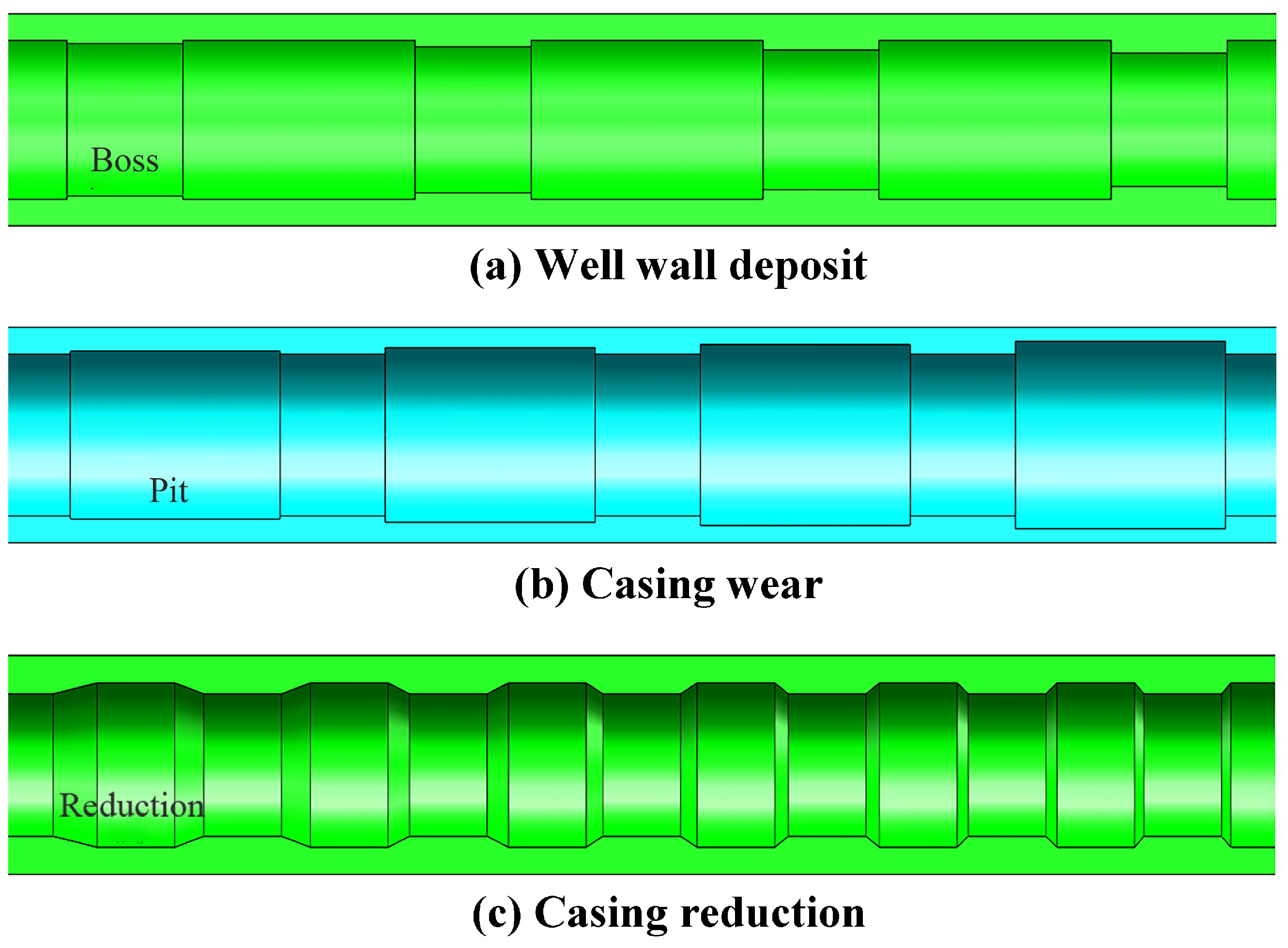
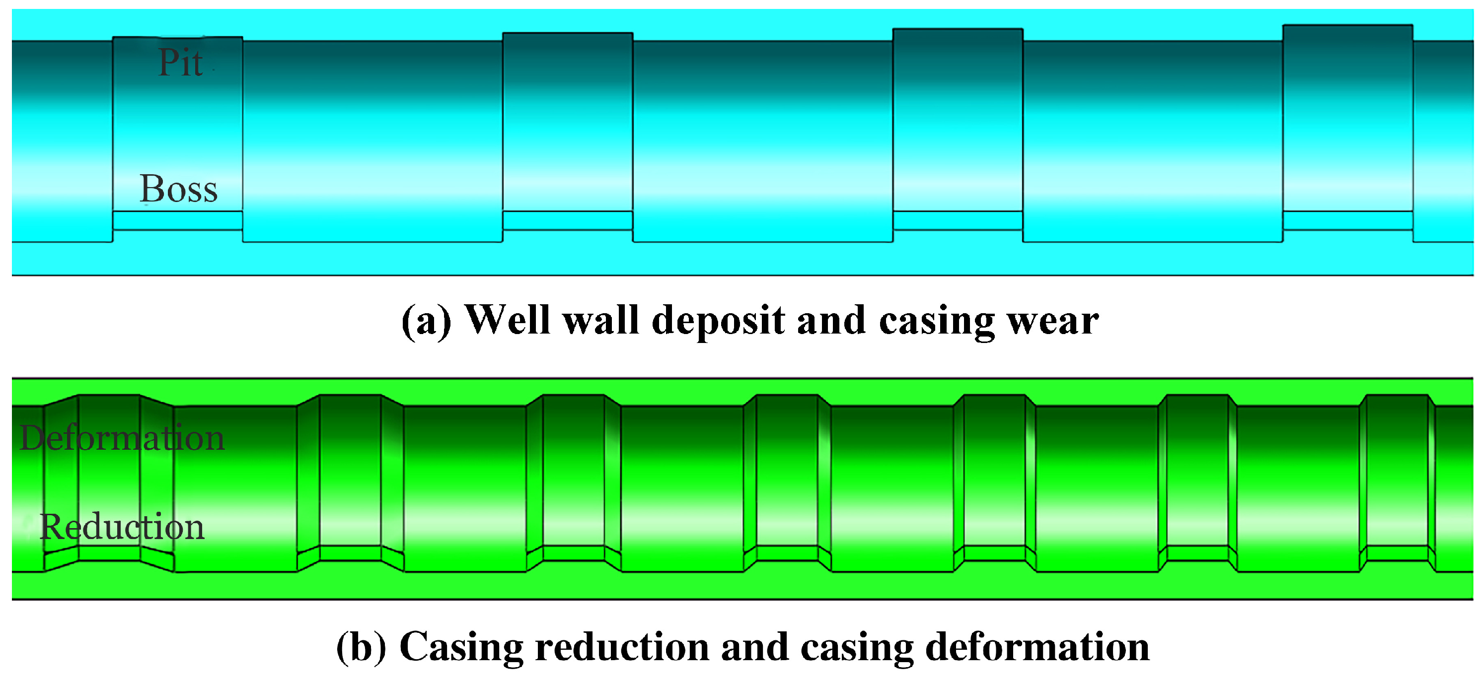
3.2. Models of Casing with Obstacle

The obstacles of the casing pipe are generally divided into well wall deposit, casing wear and casing reduction. This paper took the casing with a 150 mm inner diameter as the study object. In order to facilitate the simulation study, well wall deposit in the casing pipe was simulated with rectangular bosses with step heights of 3 mm, 6 mm, 9 mm, and 12 mm, and the length of 50 mm. Casing wear was simulated with pits with depths of 3 mm, 6 mm, 9 mm, and 12 mm, and the length of 100 mm. And casing reduction was simulated with inclination angles with 9 mm in height, 10°, 15°, 20°, 25°, 30°, 35°, and 40° in inclination angles, and 20 mm in length. The models are shown in Figure 6.
At present, scholars’ studies on the analysis of the obstacle surmounting of the propping wheels mainly focus on single obstacle such as well wall deposit, casing wear or casing reduction. Without considering studies on facing multiple obstacles simultaneously, such as well wall deposit and casing wear or casing reduction and casing deformation at different slopes. Therefore, this paper made an analysis and studies on the situation that the propping wheels encounter single obstacle when crossing the casing pipe. Meanwhile, this paper made analysis and studies on facing multiple obstacles, such as well wall deposit and casing wear, casing reduction and casing deformation at different slopes simultaneously when the propping wheels cross the casing. The models are shown in Figure 7.

4. Dynamic Characteristics of Support Adjustment Mechanism of WDR

4.1. Obstacle Surmounting Performance under Single Obstacle

The WDR with the SPRSAM and DPRDSSAM crossed through well wall deposit, casing wear and casing reduction respectively. The single obstacle in this section referred to well wall deposit, casing wear and casing reduction. The motion state and obstacle surmounting performance of the WDR were compared as follows.

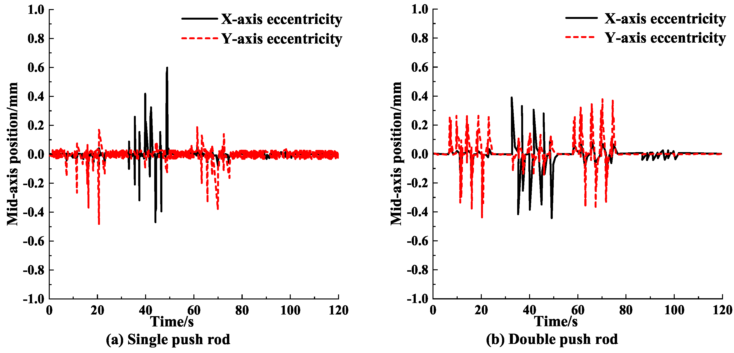
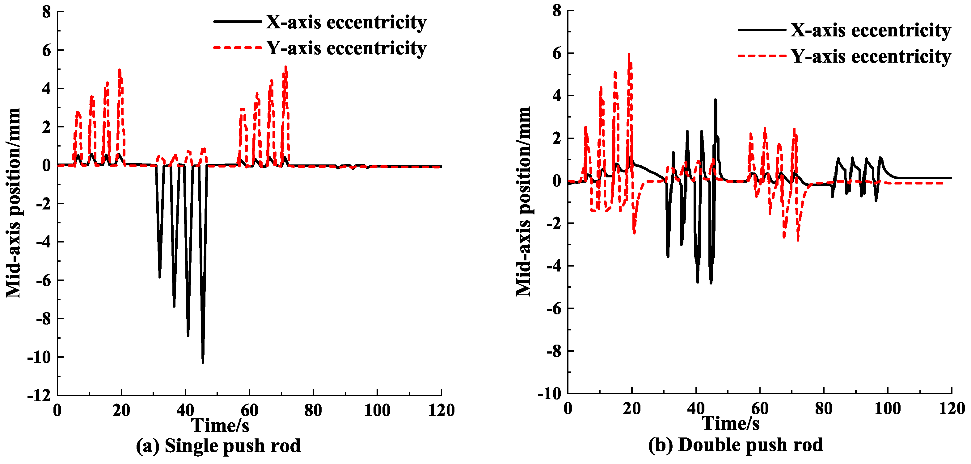
4.1.1. Mid-Axis Offset of Support Adjustment Mechanism under Single Obstacle

Figure 8, Figure 9 and Figure 10 show the displacement of the mid-axis of the SPRSAM and the DPRDSSAM under single obstacle. It can be seen from Figure 8, Figure 9 and Figure 10 that:
The SPRSAM and DPRDSSAM operated under obstacles of well wall deposit, casing wear and casing reduction. During operation, the mid-axis position of the WDR changed. The changes were not significant, indicating that both support adjustment mechanisms can maintain excellent centring performance. Both support adjustment mechanisms can ensure the normal operation of the WDR in the casing pipe under such circumstances. The mid-axis offset of the SPRSAM is greater than that of the DPRDSSAM when the propping wheels cross through the obstacles. The result indicates that the centring performance of the DPRDSSAM is better than that of the SPRSAM.
Upon analysis, both support adjustment mechanisms of the WDR can keep the excellent centring performance when crossing through well wall deposit, casing wear, and casing reduction. Meanwhile, both support adjustment mechanisms of the WDR can achieve the excellent obstacle surmounting effect. But in general, the centring performance of the DPRDSSAM is superior to that of the SPRSAM when the WDR crosses through single obstacle.

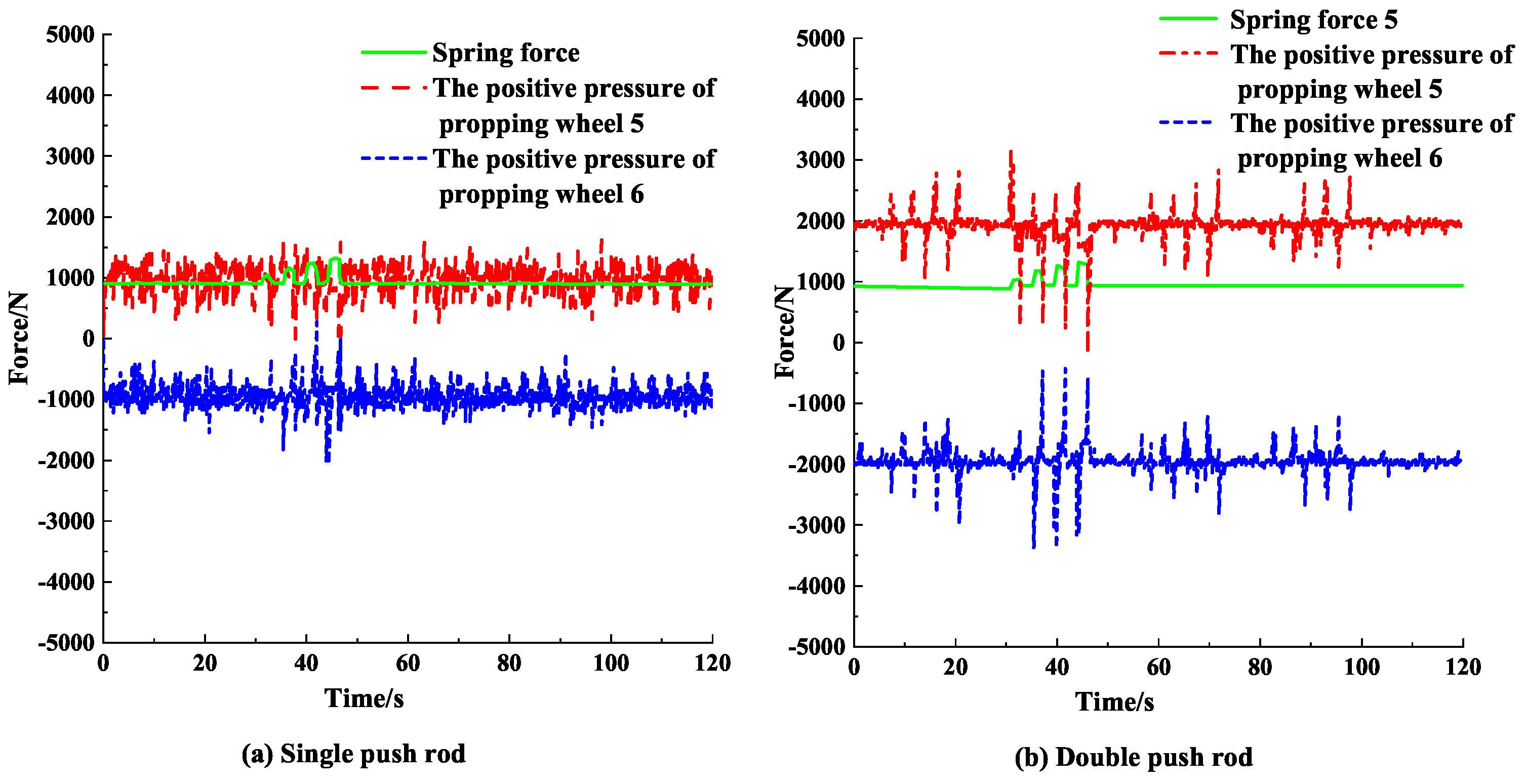
4.1.2. Positive Pressure of Support Adjustment Mechanism under Single Obstacle

Figure 11, Figure 12 and Figure 13 show the changes in the positive pres- sure of SPRSAM, and DPRDSSAM under single obsta- cle. It can be seen from Figure 11, Figure 12 and Figure 13 that:
When the propping wheels 5 and 6 ran on the inner wall of the casing pipe, springs were in the compression state. And the spring force was close to 1000 N. The spring force gradually increased when the propping wheels crossed through well wall deposit or casing reduction (Figure 11 and Figure 13). Figure 11 and Figure 13 indicate that the springs were continuously compressed when the WDR crossed well wall deposit or casing reduction. Meanwhile, the spring force continuously increased. The spring force gradually decreased when the propping wheels crossed through casing wear (Figure 12). Figure 12 indicates that the springs were continuously released when the WDR crossed casing wear. Meanwhile, the spring force continuously decreased. The adjustment effect of the springs allowed the propping wheels to continuously contact the casing, ensuring the positive pressure between the propping wheels and the casing pipe.
Under the action of the single push rod, two positive pressures of the propping wheels 5 and 6 fluctuated continuously under the acting force of 1000 N. Since the positive pressures of the two propping wheels were regulated with one spring, the positive pressure applied to the WDR can only be guaranteed at the expense of part of the centring performance. For the DPRDSSAM, the springs regulated the corresponding propping wheels respectively. And the propping wheels did not affect each other. Therefore, the positive pressure of the propping wheels continuously fluctuated under the acting force of 2000 N. The structure can ensure both the centring performance of the WDR and the effect of applying positive pressure to the propping wheel. The fluctuation of the positive pressure of the propping wheels 5 and 6 of the DPRDSSAM changed significantly. Thus the positive pressure is more sensitive to the spring force and the changing state of the tractor. The result indicates that the size of the positive pressure can be adjusted timely according to the motion state of the tractor, thus avoiding the phenomenon of lagging in the adjustment of the SPRSAM, and improving the obstacle surmounting performance of the tractor.
The above analysis shows that the two different support adjustment mechanisms of the WDR have a greater effect on the value of the positive pressure of the propping wheels. Therefore, the DPRDSSAM of the WDR can more easily meet the design requirements of the WDR as against SPRSAM. And the DPRDSSAM of the WDR is superior to the SPRSAM.

4.2. Obstacle Surmounting Performance under Multiple Obstacles

When two support adjustment mechanisms of the WDR cross well wall deposit, casing wear, and casing reduction, the DPRDSSAM is superior to the SPRSAM. The casing obstacles show symmetrical changes in the X-axis and the Y-axis. Therefore, the effect advantage of the DPRDSSAM in the obstacle surmounting performance is not embodied fully. Only a single state of well wall deposit, casing wear or casing reduction has been discussed above. Multiple obstacles in this section referred to well wall deposit and casing wear, casing reduction and casing deformation. Therefore, the section focused on discussing the effect of the two support adjustment mechanisms of the WDR on the obstacle surmounting performance when the WDR crossed through the well wall deposit and casing wear, casing reduction and casing deformation.

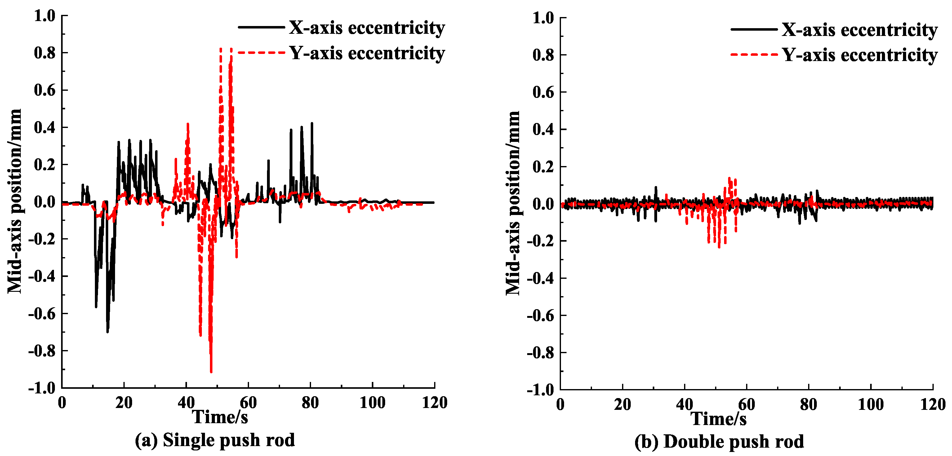
4.2.1. Mid-Axis Offset of Support Adjustment Mechanism under Multiple Obstacles

Figure 14 and Figure 15 show the displacement of the mid-axis of the SPRSAM, and DPRDSSAM under multiple obstacles. It can be seen from Figure 14 and Figure 15 that:
When the two support adjustment mechanisms crossed through well wall deposit and casing wear, casing reduction and casing deformations, the mid-axis positions of the two support adjustment mechanisms changed. When the WDR with the two support adjustment mechanisms crossed through the obstacles, the offsets of the WDR at the mid-axis positions were caused, only with the offset amount being different. The maximum off-centre value of the X-axis is 10 mm and the maximum off-centre value of the Y-axis is 6 mm when the WDR with the SPRSAM crossed through well wall deposit and casing wear, casing reduction and casing deformation. The maximum off-centre value of the X-axis is 5 mm and the maximum off-centre value of the Y-axis is 6 mm when the WDR with the DPRDSSAM crossed through well wall deposit and casing deformation, casing reduction and casing deformation. When the WDR crossed through the same obstacles, the offset of the DPRDSSAM at the mid-axis position is smaller than that of the SPRSAM at the mid- axis position. The maximum eccentricity value of the obstacles in the casing pipe is 12 mm. For the SPRSAM, the maximum value of the mid-axis eccentricity of the tractor is 10 mm. The centring performance of the SPRSAM is poor, which causes a collision between the tractor and the inner wall of the casing pipe, resulting in failure to the obstacle crossing of the wheeled tractor. For DPRDSSAM, the off-centre maximum value of the tractor is only 6 mm. Each adjustment spring of the DPRDSSAM corresponds to a push rod and drives a propping wheel to move radially. So even when the propping wheel crosses well wall deposit and casing wear simultaneously, the propping wheel can still maintain the excellent centring performance, which can better avoid any accident caused by the excessive mid-axis offset in the tractor.
It can be known from the above analysis: When the WDR crosses through the well wall deposit and casing wear, casing reduction and casing deformation, the WDR with the DPRDSSAM has a higher centring performance.

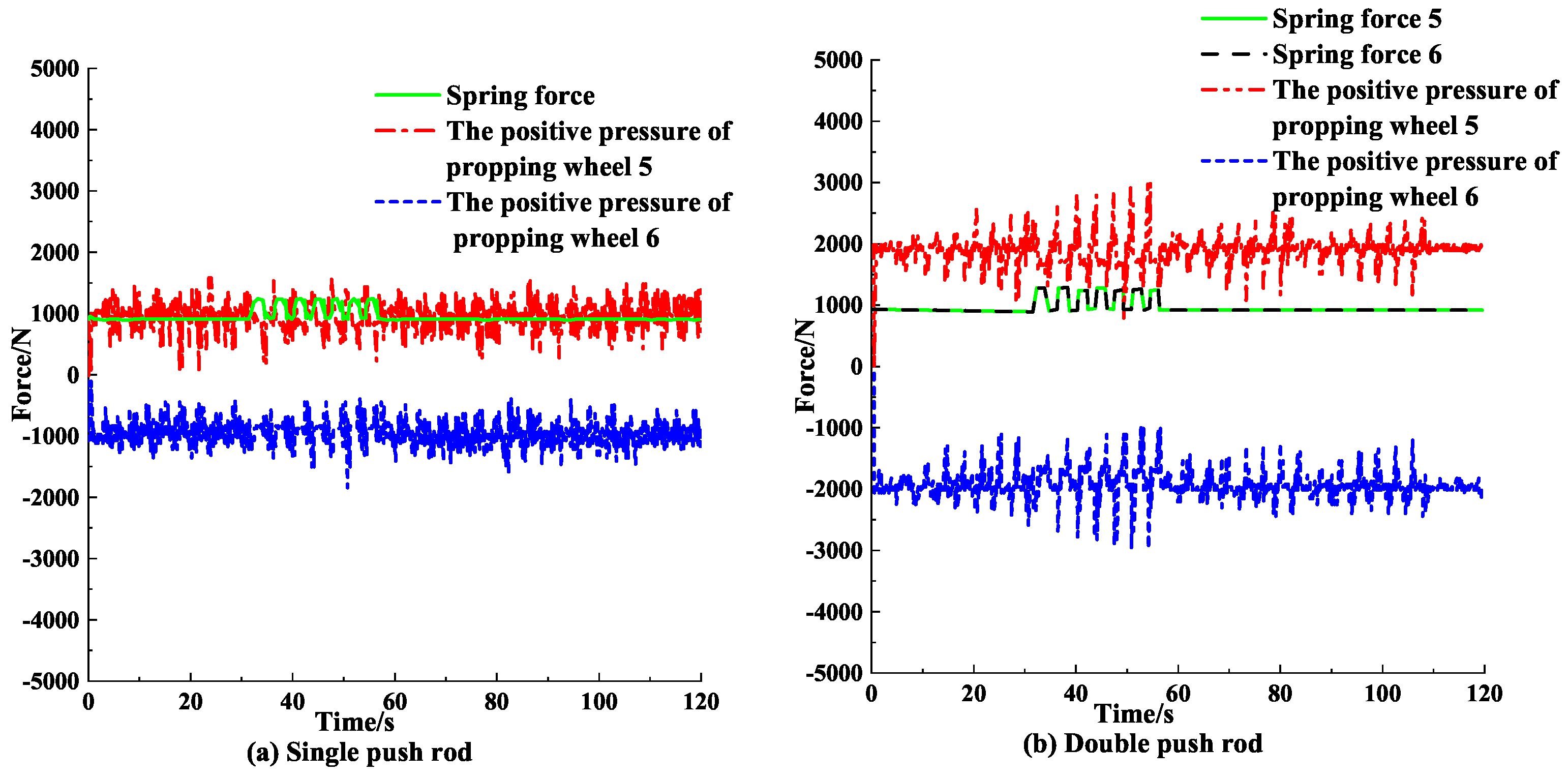
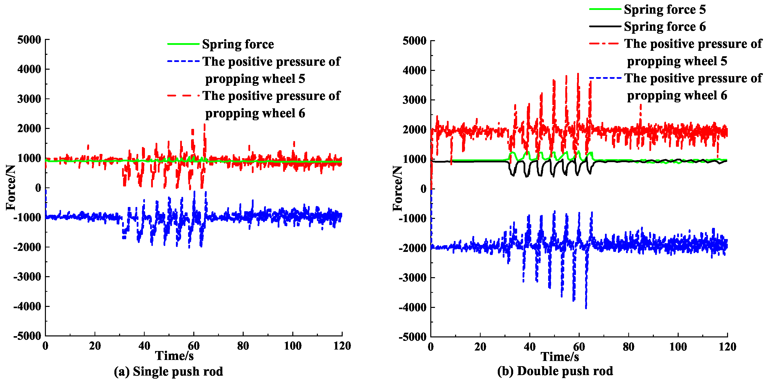
4.2.2. Positive Pressure of Support Adjustment Mechanism under Multiple Obstacles

Figure 16 and Figure 17 show the changes in the positive pressure of SPRSAM, and DPRDSSAM under multiple obstacles. It can be seen from Figure 16 and Figure 17 that:
Figure 16a and Figure 17a show that when the WDR with the SPRSAM operated in the casing pipe, the spring was in a compressed state. And the spring force was about 1000 N. The propping wheels 5 and 6 were under positive pressure. And the positive pressures of propping wheels 5 and 6 were about 1000 N. When the WDR operated to about 40 s, the propping wheels 5 and 6 started to cross the obstacles. In the presence of well wall deposit, casing reduction, the spring can only be compressed and cannot extend to adapt to casing wear, casing deformation. The spring force began to fluctuate and the positive pressures of the propping wheels also began to fluctuate to adapt changes in the spring force. The obstacles on one side of the propping wheels are casing wear and casing reduction. Therefore, in order to keep contact between the propping wheels and the casing pipe, the WDR can make the propping wheels 5 and 6 contact the casing pipe simultaneously only by the off-centre of the mid-axis, resulting in poor centring performance in the tractor. Figure 16b and Figure 17b show that the spring forces of springs 5 and 6 were about 2000 N and the positive pressures of propping wheels 5 and 6 were about 2000 N. At the 40 s, one spring was compressed, and the other was extended. Therefore, the spring force of one spring increased, while the other reduced. The springs regulated one propping wheel respectively, the propping wheels can be regulated according to respective the situation of the obstacles. Therefore, the DPRDSSAM can keep a better centring performance. Upon comparison with fluctuation in the positive pressure, it can be found that the positive pressure of the DPRDSSAM is more sensitive to the operating situation of the tractor and better in the feedback effect. The DPRDSSAM can quickly adjust the compression or extension state of the springs and can adapt to a complex environment in the casing pipe as against the SPRSAM.
Upon analysis, it can be known that when the WDR crosses through well wall deposit and casing wear, casing reduction and casing deformation, the DPRDSSAM is superior to the SPRSAM.

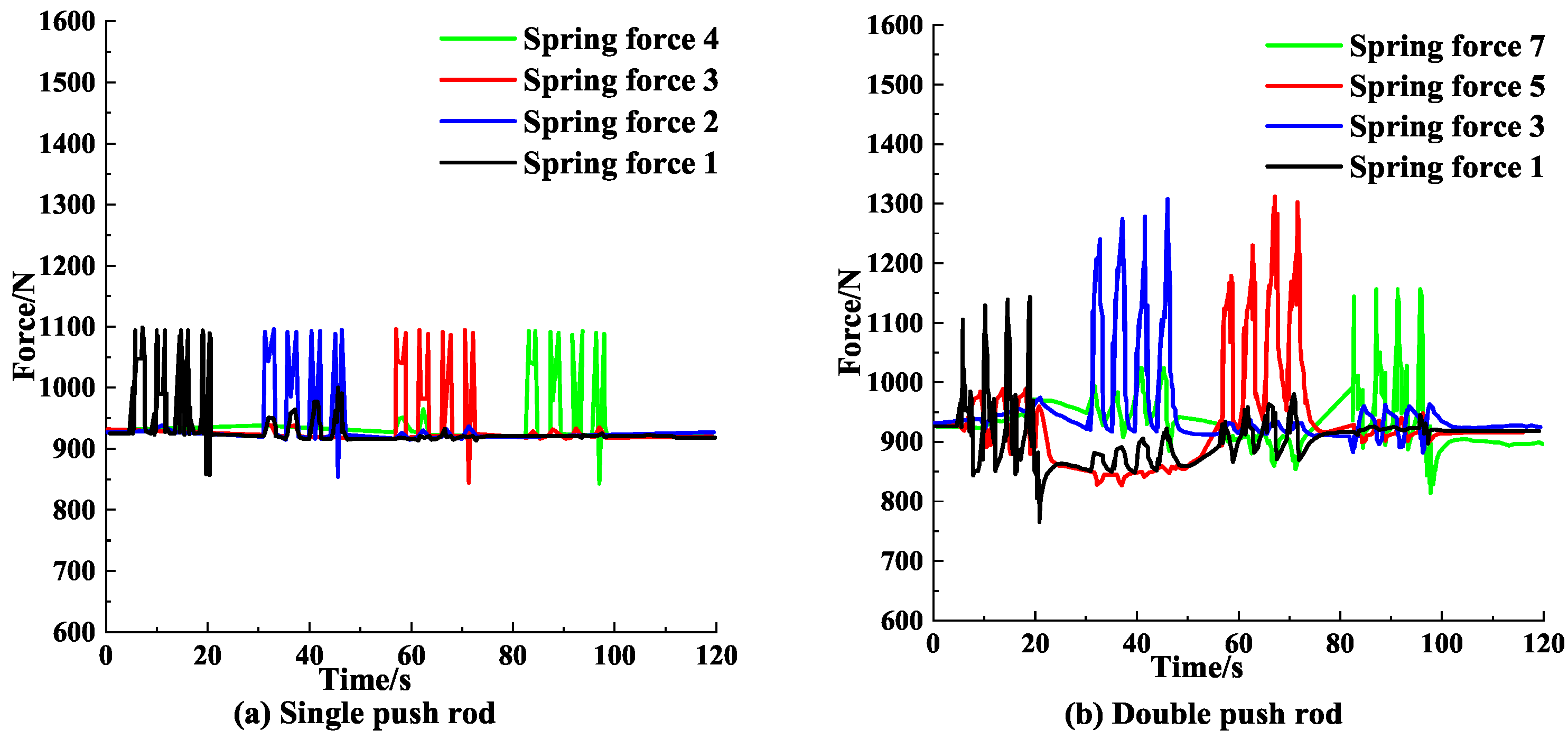
4.2.3. Spring Force of Support Adjustment Mechanism under Multiple Obstacles

Figure 18 and Figure 19 show the changes in the spring force of SPRSAM, and DPRDSSAM under multiple obstacles. It can be seen from Figure 18 and Figure 19 that:
Figure 18a shows that the spring force in the WDR with the SPRSAM changed four times, with four-wave crests with equal heights. Figure 19a shows that the spring force in the WDR with the SPRSAM changed four times, with seven gradually elevated wave crests for each time. The states just correspond to the situation that the four pairs of the propping wheels crossed the four well wall deposits (with equal heights) and seven gradually increasing casing reductions. For the obstacles caused by casing wear and casing reduction, the adjustment spring can not be adjusted. Under the action of the centring guide, if the tractor keeps centred forcibly, which makes the propping wheels that crossing casing wear keeps in the suspended state, resulting in the incapability of providing tractive force. Figure 18b and Figure 19b show that changes in the spring force of the DPRDSSAM just corresponded to changes that the four propping wheels crossed the obstacles. The result indicates that the propping wheels can still keep in contact with the borehole wall under multiple obstacles and provide the tractive force required for the tractor. Upon comparison, the spring force of the DPRDSSAM fluctuated more greatly and the fluctuation was more complex. This is because the tractor crosses the obstacles, and the DPRDSSAM is more sensitive in response and quicker in feedback. And when the tractor crosses complex obstacles, the motion status of the tractor can be fed back more quickly. The action of the springs can be regulated timely so that the positive pressure between the propping wheels and the casing pipe can be adjusted timely according to the motion status of the tractor.
Upon analysis, the SPRSAM can only adapt to the four well wall deposits with equal heights and seven casing reductions which increased gradually. And the SPRSAM can not adapt to four casing wears which are aggravated gradually and seven casing deformations which are reduced gradually. The DPRDSSAM can adapt to the four well wall deposits with equal heights and seven casing reductions which are increased gradually. The DPRDSSAM also can adapt to four casing wears which are aggravated gradually and seven casing deformations which are reduced gradually. Therefore, the DPRDSSAM is superior to the SPRSAM when the WDR crosses through well wall deposit and casing wear, casing reduction and casing deformation.

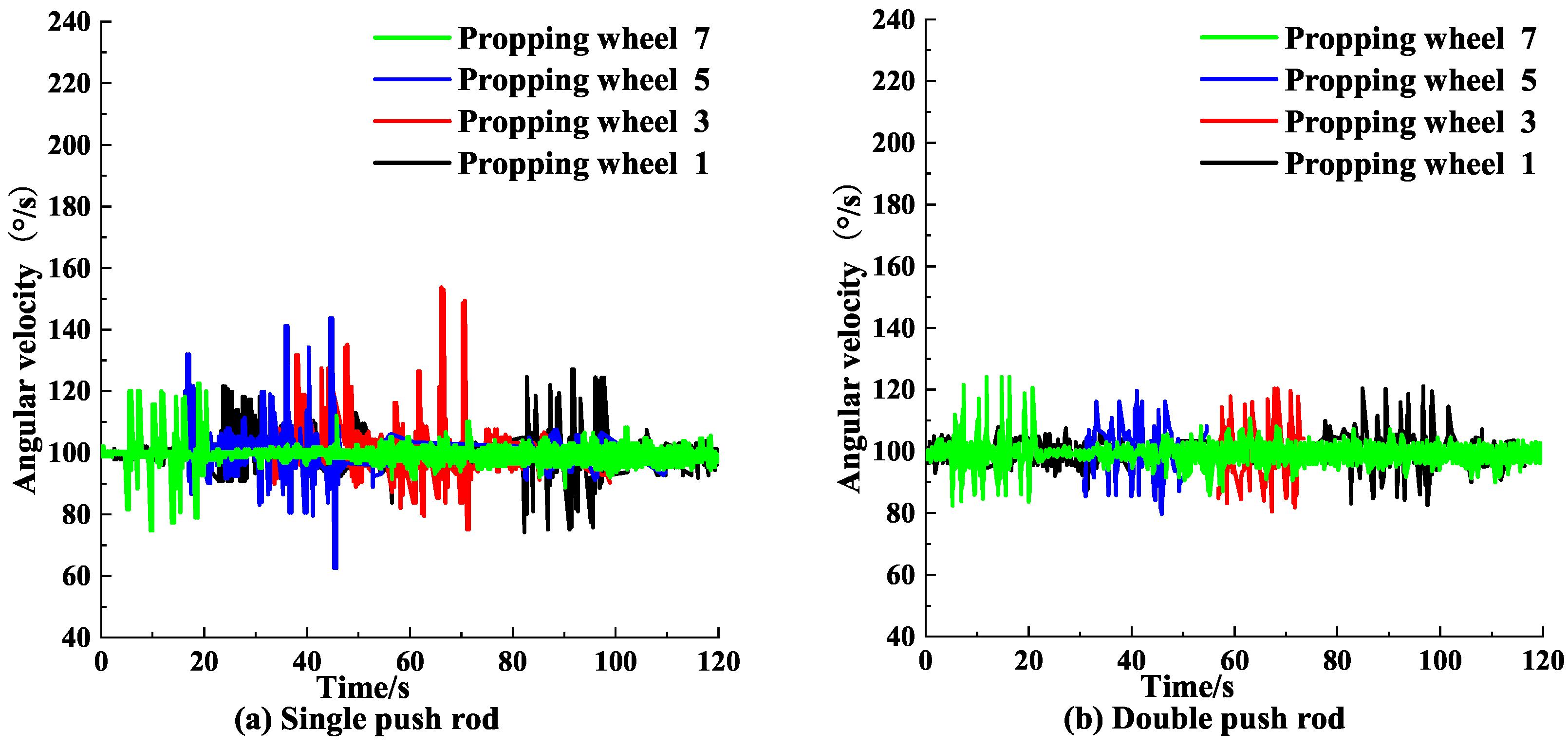
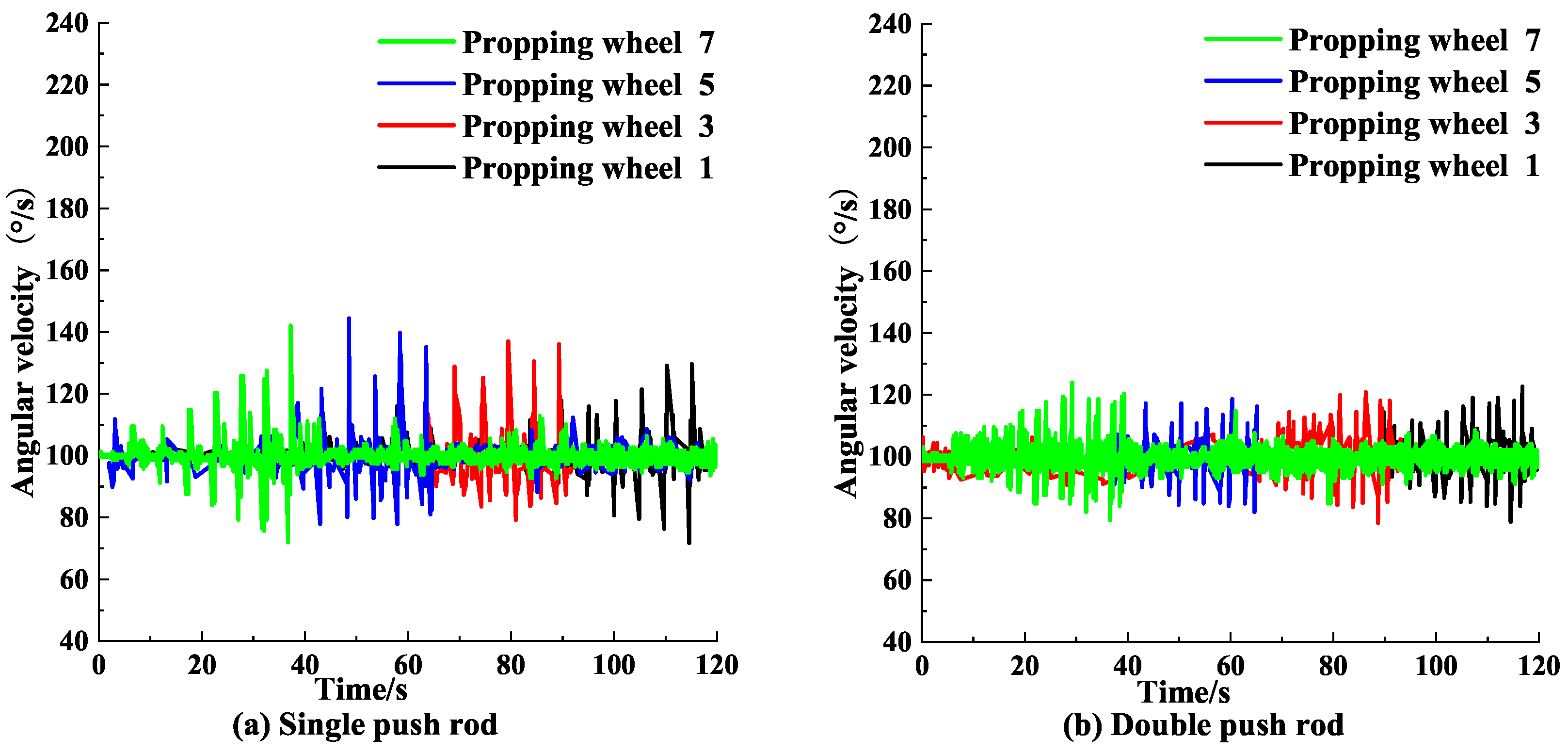
4.2.4. Angular Velocity of Support Adjustment Mechanism under Multiple Obstacles

Figure 20 and Figure 21 show the changes in the angular velocity of SPRSAM, and DPRDSSAM under multiple obstacles. It can be seen from Figure 20 and Figure 21 that:
When the WDR with two different support adjustment mechanisms ran in the casing pipe, the propping wheels fluctuated. In order to avoid seizing when the WDR cross through the barrier, the differential speed between the obstacles crossing propping wheels needs to be formed by changing the angular velocity. When the propping wheels of two support adjustment mechanisms of the WDR didn’t cross the obstacles, the angular velocity was kept at 100 deg/s. Meanwhile, when the propping wheels crossed through well wall deposit and casing wear, casing reduction and casing deformation, the angular velocity changed. The SPRSAM is large in the change in the angular velocity when the propping wheels cross through the obstacles. The torque of the propping wheels of the SPRSAM is increased when the propping wheels cross the obstacles. So that the angular velocity is increased in fluctuation, and the service life of the drive motor is reduced. Therefore, the DPRDSSAM is superior to the SPRSAM when the WDR simultaneously crosses through well wall deposit and casing wear, casing reduction and casing deformation.

5. Discussion

From above six simulations, the proposed WDR with the DPRDSSAM provides the proper positive pressure between the propping wheels and the inner wall of the casing pipe. The WDR with the DPRDSSAM have an outstanding obstacle surmounting performance as against that with the SPRSAM under single obstacle or multiple obstacles. In many of studies on wheeled downhole tractor, the driving system and the mechanical characteristic are studied deeply. However, the support adjustment mechanism plays an important role in the advancement of the WDR. Through a suitable and excellent support adjustment mechanism, the force state between the support wheel and the inner wall of the casing is adjusted. Through the double push rod structure, the WDR adapt to a series of obstacles such as different well wall deposit, casing wear, casing reduction, casing deformation in the casing pipe. Based on above simulations, the obstacle surmounting performance of the DPRDSSAM is verified from the mix-axis offset, positive pressure, spring force and angular velocity. The above four physical quantities are the main evidences for testing the traction effect of the WDR. However, there are many factors that affect the movement of the WDR in horizontal wells. This study do not take into account all the influencing factors. The DPRDSSAM needs more verification to meet more requirements of downhole operations.
In the subsequent work, more physical quantities that affect motion will be studied. In the next work, the support adjustment mechanism of the WDR is an important research direction and content. The driving system of the WDR also is the research direction. The excellent driving system and appropriate support adjustment mechanism make the WDR better transport the instrument in the casing pipe.

6. Conclusions

In this paper, a novel WDR with the DPRDSSAM of based on push rods and adjustment springs was proposed. The SPRSAM and the proposed DPRDSSAM have consistent effects on changes in the centre position of the propping wheel and angular speed of the propping wheel when crossing through well wall deposit, casing wear and casing reduction. Meanwhile, The SPRSAM and the DPRDSSAM have large effects on differences in the mid-axis position of the WDR and changes in the positive pressure of the propping wheel of the WDR. The DPRDSSAM has better centring performance and can provide larger positive pressure than the SPRSAM. The mid-axis maximum eccentricity of the wheel downhole tractor with SPRSAM is 10 mm under multiple obstacles. The mid-axis maximum eccentricity of the wheel downhole tractor with DPRDSSAM is 6 mm under multiple obstacles. The angular velocity of DPRDSSAM has a lesser fluctuation as against SPRSAM under multiple obstacles. The spring force of the DPRDSSAM has a greater fluctuation as against SPRSAM under multiple obstacles. The results show that the WDR with the DPRDSSAM is superior to the WDR with the SPRSAM in adaption to changes in the diameters of the casing pipe, and the motion state of the traction can be fed back quickly. When the WDR crosses through the obstacles, the DPRDSSAM is superior to the SPRSAM in obstacle surmounting performance. The WDR with the DPRDSSAM has better obstacle casing adaptability. The WDR with the DPRDSSAM has a longer service life than the WDR with the SPRSAM.
Based on the above results, the proposed DPRDSSAM the proposed DPRDSSAM can effectively improve the adaptability and application of the WDR in the open hole well. In petroleum engineering, there are multiple casing obstacle forms on the inner wall of the casing pipe. The WDR with the DPRDSSAM is more suitable for transporting instruments in casing with multiple casing obstacles in the future. The research results of this paper lay a way of solving the adaptability of the WDR under the open hole well and other complex conditions. It can effectively ensure the downhole safety of oil and gas wells.

Author Contributions

J.Z., conceptualization, methodology, writing—original draft, funding acquisition; X.Z., writing—review and editing, software, data curation; X.W., investigation, supervision; X.L., writing—review and editing; X.D., writing—review and editing, resources. All authors have read and agreed to the published version of the manuscript.

Funding

National Natural Science Foundation of China (No. 52004232, U19A200380), Sichuan Province Science and Technology Support Program (23QYCX0060, JG2021-624, 2021YFS0305, 22YFQ0061) and Sichuan Provincial Key Lab of Process Equipment and Control (GK202006).

Institutional Review Board Statement

Not applicable.

Informed Consent Statement

Not applicable.

Data Availability Statement

There is no associate data in this study.

Acknowledgments

This work was supported by Sichuan Guangtai Construction Project Management Co., Ltd. We thank Sichuan Guangtai Construction Project Management Co., Ltd. for providing suggestions.

Conflicts of Interest

The authors declare no conflflict of interest.

Abbreviations

The following abbreviations are used in this manuscript:
WDRwheeled downhole tractor
DPRDSSAMdouble push rod-double spring support adjustment mechanism
SPRSAMsingle push rod support adjustment mechanism

References

  1. Shang, J.Z.; Fang, D.L.; Luo, Z.R.; Wang, R.; Li, X.; Yang, J.H. Design and analysis of a hydraulic drive downhole traction in-pipe robot based on flexible support structure. Proc. Inst. Mech. Eng. Part C. 2021, 235, 18–27. [Google Scholar] [CrossRef]
  2. Zhao, J.G.; Han, S.; Liu, Q.Y.; Zhang, Y.; Xiao, X.H.; Dong, R.; Fang, S.J.; Tu, C. Combined control mechanism of WOB and ROP with downhole robot in coiled tubing drilling process. SPE J. 2022, 27, 153–166. [Google Scholar] [CrossRef]
  3. Castillo, H.C.; Turner, D.R.; Smalley, E.A. Extreme production logging in long horizontal wells with high flow rates using downhole tractors. In Proceedings of the Onepetro SPE Annual Technical Conference and Exhibition, Denver, CO, USA, 21 September 2008. [Google Scholar]
  4. Tian, J.L.; Yang, Z.; Li, Y.; Yang, L.; Wu, C.M.; Liu, G.; Yuan, C.F. Vibration analysis of new drill string system with hydro-oscillator in horizontal well. J. Mech. Sci. Technol. 2016, 30, 2443–2451. [Google Scholar] [CrossRef]
  5. Dong, Y. Analysis of key technology and application of horizontal well production logging technology. Petrochem. Ind. Technol. 2017, 24, 125. [Google Scholar]
  6. Fang, D.L.; Shang, J.Z.; Liu, Y.Y.; Wu, W.; Luo, Z.R. Development of a drilling fluid drive downhole tractor in oil field. IOP Conf. Ser. Earth Environ. Sci. 2018, 111, 012007. [Google Scholar] [CrossRef] [Green Version]
  7. Gao, S.; Sun, W.; Ni, H.; Chang, Y.L. Status and understandings of downhole tractor design. J. Mach. Des. 2014, 31, 1–8. [Google Scholar]
  8. Saeed, A.; Duthie, L.; Yaklovlev, T.; Sagr, H. Development and world’s first field deployment of 2.125 tridem coiled tubing tractor for extended reach open hole horizontal wells with esp completions. In Proceedings of the Abu Dhabi International Petroleum Exhibition & Conference, Abu Dhabi, United Arab Emirates, 13 November 2017. [Google Scholar]
  9. Tyagi, C.; Singh, V.; Nayak, J.P.; Pinto, T. Unique milling bit deployed via e-line intervention enables operator to achieve early production. In Proceedings of the SPE/ICoTA Coiled Tubing and Well Intervention Conference and Exhibition, Houston, TX, USA, 21–22 March 2017. [Google Scholar]
  10. Hou, X.J.; Gao, D.L.; Shen, Z.H. Structure design of coiled tubing tractor driven by motor in micro hole. Sci. Technol. Eng. 2013, 13, 1671–1815. [Google Scholar]
  11. Zhao, Q.M.; Fan, J.C.; Yan, D.; Tian, R.R.; Zhou, B.; Li, C. Development of downhole tools for stratified testing in oil and gas open-hole wells. Adv. Mat. Res. 2012, 422, 614–618. [Google Scholar] [CrossRef]
  12. Tan, L.C.; Gao, D.L. Casing wear prediction model based on casing ellipticity in oil and gas well-drilling with complex structures. J. Appl. Mech. 2018, 85, 101005. [Google Scholar] [CrossRef]
  13. Chen, L.F.; Gao, D.L.; Sun, T.F. Characteristics of process of surmounting obstacles by downhole tractors in horizontal shafts. Chem. Technol. Fuels Oil 2017, 53, 569–578. [Google Scholar] [CrossRef]
  14. Liu, Q.Y.; Zhao, J.G.; Zhu, H.Y.; Zheng, W.; Yang, Y.Q. A novel double bevel support structure for downhole robot. Arab. J. Sci. Eng. 2019, 44, 1069–1079. [Google Scholar] [CrossRef]
  15. Liu, Q.Y.; Zhao, J.G.; Zhu, H.Y.; Wang, G.R. Review, classification and structural analysis of downhole robots: Core technology and prospects for application. Rob. Auton. Syst. 2019, 115, 104–120. [Google Scholar] [CrossRef]
  16. Schwanitz, B.; Henriques, K. The development of wireline-tractor technology. Way Ahead. 2009, 5, 18–20. [Google Scholar] [CrossRef]
  17. Stuart-Bruges, W.P.; Searight, T.L.; Harris, N.G. Centralizer for Wireline Tools. U.S. Patent 7090007, 15 August 2006. [Google Scholar]
  18. Doering, F.W.; Sheiretov, T.K.; Ewan, R.A.; SSDD. Traction Control for Downhole Tractor. U.S. Patent 7143843, 5 December 2006. [Google Scholar]
  19. Sheiretov, T. Wireline tractors and mechanical services tools: Comparative study of technical solutions. In Proceedings of the SPE/ICoTA Coiled Tubing and Well Intervention Conference and Exhibition, Houston, TX, USA, 22–23 March 2016. [Google Scholar]
  20. Wang, C.C. Approximate boolean operations on large polyhedral solids with partial mesh reconstruction. IEEE Trans. Vis. Comput. Graph. 2010, 17, 836–849. [Google Scholar] [CrossRef] [PubMed]
  21. Phuoc, L.M.; Martinet, P.; Lee, S.; Kim, H. Damped least square based genetic algorithm with Ggaussian distribution of damping factor for singularity-robust inverse kinematics. J. Mech. Sci. Technol. 2008, 22, 1330–1338. [Google Scholar] [CrossRef]
Figure 1. The overall structure model of the WDR with the push rod−spring support adjustment mechanism.
Processes 11 00140 g001
Figure 2. Structures of single push rod support adjustment mechanism.
Processes 11 00140 g002
Figure 3. Structures of double push rod−double spring support adjustment mechanism.
Processes 11 00140 g003
Figure 4. ADAMS simulation models of single push rod support adjustment mechanism, double push rod−double spring support adjustment mechanism.
Processes 11 00140 g004
Figure 5. Three−dimensional model of wheeled downhole tractor.
Processes 11 00140 g005
Figure 6. Simulated casing with single obstacle.
Processes 11 00140 g006
Figure 7. Simulated well wall deposit and casing wear, casing reduction and casing deformation.
Processes 11 00140 g007
Figure 8. The displacement of the mid−axis of the single push rod support adjustment mechanism, double push rod−double spring support adjustment mechanism under well wall deposit obstacle.
Processes 11 00140 g008
Figure 9. The displacement of the mid−axis of the single push rod support adjustment mechanism, double push rod−double spring support adjustment mechanism under casing wear obstacle.
Processes 11 00140 g009
Figure 10. The displacement of the mid−axis of the single push rod support adjustment mechanism, double push rod−double spring support adjustment mechanism under casing reduction obstacle.
Processes 11 00140 g010
Figure 11. The change of positive pressure of single push rod support adjustment mechanism, double push rod−double spring support adjustment mechanism under the barrier of well wall deposit.
Processes 11 00140 g011
Figure 12. The change of positive pressure of single push rod support adjustment mechanism, double push rod−double spring support adjustment mechanism under the barrier of casing wear.
Processes 11 00140 g012
Figure 13. The change of positive pressure of single push rod support adjustment mechanism, double push rod−double spring support adjustment mechanism under the barrier of casing reduction.
Processes 11 00140 g013
Figure 14. The displacement of the mid−axis of the single push rod support adjustment mechanism, double push rod−double spring support adjustment mechanism across the well wall deposit and casing wear.
Processes 11 00140 g014
Figure 15. The displacement of the mid−axis of the single push rod support adjustment mechanism, double push rod−double spring support adjustment mechanism across the casing reduction and casing deformation.
Processes 11 00140 g015
Figure 16. The positive pressure change of propping wheel of single push rod support adjustment mechanism, double push rod−double spring support adjustment mechanism when crossing the well wall deposit and casing wear.
Processes 11 00140 g016
Figure 17. The positive pressure change of propping wheel of single push rod support adjustment mechanism, double push rod−double spring support adjustment mechanism when crossing the casing reduction and casing deformation.
Processes 11 00140 g017
Figure 18. The change of spring force of single push rod support adjustment mechanism, double push rod−double spring support adjustment mechanism when crossing the well wall deposit and casing wear.
Processes 11 00140 g018
Figure 19. The change of spring force of single push rod support adjustment mechanism, double push rod−double spring support adjustment mechanism when crossing the casing reduction and casing deformation.
Processes 11 00140 g019
Figure 20. The change of the angular velocity of the support wheel of the single push rod support adjustment mechanism, double push rod−double spring support adjustment mechanism when crossing the well wall deposit and casing wear.
Processes 11 00140 g020
Figure 21. The change of the angular velocity of the support wheel of the single push rod support adjustment mechanism, double push rod−double spring support adjustment mechanism when crossing the casing reduction and casing deformation.
Processes 11 00140 g021
Table 1. Correlation coefficient between propping wheel and casing.
ParameterNumerical ValueParameterNumerical Value
Damping coefficient10Contact rigidity (N/mm)10 5
Force index2.2Penetration depth (mm)0.2
Disclaimer/Publisher’s Note: The statements, opinions and data contained in all publications are solely those of the individual author(s) and contributor(s) and not of MDPI and/or the editor(s). MDPI and/or the editor(s) disclaim responsibility for any injury to people or property resulting from any ideas, methods, instructions or products referred to in the content.

