Abstract
The doubly fed induction generator (DFIG) is vulnerable to grid faults due to its direct stator connection, causing issues like excess stator current during voltage dips. Consequently, sensitive inverters suffer from increased currents, and the DC-link capacitor undergoes overcharging. This document examines two protection strategies employing a proportional–integral (PI) controller to manage the transient rotor current and mitigate DC-link overcharging, thereby optimizing DFIG behavior during network faults. One option combines a classic crowbar circuit with a DC-chopper, while the other is a modified protection scheme (MPS) that includes an impedance with passive elements and a crowbar. The impedance forms a resistance Rp parallel with an inductance Lp. Both configurations, situated between the rotor coils and the rotor-side converter (RSC), augment the capacity for low-voltage ride-through (LVRT). MATLAB/SIMULINK simulations of the two schemes demonstrate successful rotor current reduction at 2.9 kA and 3.4 kA, and DC-link tension reduction below and at 1.4 KV. In addition, the conventional crowbar and MPS configurations efficiently restrict the RSC current to levels below 0.21 kA and 2.94 kA, while absorbing up to 2.52 kA and 1.52 kA, respectively. The key difference lies in the fact that fine-tuning the parameters in the MPS design prevents rotor disconnection when faced with a balanced fault. This enhancement enhances machine performance and enables full stator power control via the RSC.
1. Introduction
The growing use of electricity derived from fossil fuels and nuclear power, both of which come with environmental risks, is prompting scientists to actively pursue sustainable solutions. Wind energy has arisen as a substantial and complex source of environmentally friendly energy in the worldwide economy [1,2]. Among the various wind power generation systems, DFIG currently stands out as the most extensively employed technology, particularly in wind energy production facilities with capacities surpassing 1 MW [3,4]. Conversely, DFIG is an asynchronous generator with a wound rotor, where its stator is connected to the electrical grid without requiring an external power source, while the rotor is linked to the electrical network via two inverters, which are reversible static-power frequency converters Haut du formulaire [5]. Utilizing a control system to oversee the converters allows for the continuous improvement of power generation by identifying the ideal point for maximum power generation, known as the MPPT strategy [6].
Due to its dependence on power electronics and its integration with the power network, the DFIG is vulnerable to grid faults, particularly when confronted with balanced voltage dips in the grid. Therefore, this scenario can give rise to heightened stator current peaks, oscillations in active and reactive stator power, and fluctuations in electromagnetic torque [7,8]. Moreover, the sturdy electromagnetic connection between the stator and rotor facilitates the efficient transmission of peak currents from the rotor to the sensitive power inverters [9]. Should this situation manifest, it has the potential to cause overcharging of the DC-link capacitor and the rotor converters to operate in excess of their safety thresholds. Consequently, the converters might experience degradation, potentially leading to a scenario where the user is unable to utilize the power control capabilities of the DFIG even after the fault has been rectified. The initial idea for safeguarding the converter from damage during a balanced fault involved isolating the DFIG from the electrical grid through disconnection. The extensive integration of wind turbines into the electric grid creates difficulties when it comes to restoring network voltage due to their significant presence. This has prompted network experts to formulate stringent network codes, which require wind turbines to maintain their connection during network faults and, in certain situations, supply reactive energy to the electrical grid to aid in restoring its voltage levels [10]. In Figure 1, you can see the LVRT curve as described in this document. It outlines that wind turbines must stay connected to the network during short-circuit faults, provided that the voltage at the point of common coupling (PCC) remains higher than the continuous voltage level.
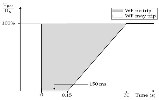
Figure 1.
The requirements for voltage at the PCC [11].
To ensure continuous network connectivity during disturbances, the system should incorporate fault ride-through (FRT) techniques that enable it to overcome faults. Many different FRTs in the literature have been proposed and can be classified as follows: integrating an additional device for protection [12,13,14,15,16,17,18,19,20] and implementing a reactive power supply [21,22,23,24,25]. The protection device that is most commonly used is the “crowbar with DC-chopper”-type resistor. The crowbar consists of a unique combination of resistor banks [26,27] that are placed in series via an IGBT switch with the rotor windings, and the DC-chopper consists of unique resistors placed in parallel through an IGBT switch with the capacitor of the DC-link. In the course of the fault, the RSC is uncoupled from a rotor, and collector rings are commutated toward the crowbar resistors. Consequently, the DFIG becomes similar to a generator with a squirrel cage, which necessitates reactive energy from the network that establishes a voltage drop at the point where the park is linked. Furthermore, the RSC disconnection to the rotor causes a loss of regulation of the active and reactive stator power.
In the context of this research, we present a modified protection scheme (MPS) designed for DFIG systems. The primary goal is to improve the wind farm’s dynamic behavior, specifically by enhancing its capability in low-voltage ride-through (LVRT) scenarios. Subsequently, we proceed to compare this MPS with a configuration that incorporates a crowbar along with a DC-chopper, particularly in situations where voltage dips occur. The MPS includes a single crowbar assembly alongside RpLp devices in parallel, and it does not rely on a DC-chopper circuit to manage limited DC-link voltage, as described in [16]. Under conditions of balanced voltage dips, power is harvested from the rotor coils, and then, delivered to the RSC. Moreover, in multiple simulation outcomes, we manage to eliminate the need for a DC-chopper circuit by selecting more appropriate RpLp values. In conclusion, we effectively accomplish a reduction in the elevated rotor current, maintain a restricted intermediate circuit voltage, and sustain the connection between the RSC and the rotor. Additionally, the generator is partially constructed as a DFIG, which results in a decreased need for reactive energy from the grid and enables the precise regulation of both active and reactive stator power output. This presents a notable advantage when contrasted with the conventional approach involving a crowbar and a DC-chopper.
This document comprises several sections. Section 2 focuses on the modeling and control of the wind turbine and DFIG using a PI controller. This is followed by Section 3, in which we introduce a protective scheme against excess rotor current for the DFIG. We showcase the scheme’s effectiveness by contrasting it with the conventional approach in a MATLAB/Simulink-based simulation of a balanced voltage dip in Section 4. Finally, in Section 5, the document is concluded.
2. Modeling the System of a Wind Farm
The wind farm being discussed consists of ten wind turbines that use rotor windings within induction generators in combination with a three-phase power grid. The generators’ stator coils have a direct connection to the grid. To establish a connection for the rotor coils with the electrical networks, an AC/DC/AC power inverter with variable frequency is employed. This inverter comprises components such as the RSC, DC-link, GSC (grid-side converter), and RfLf filter, as shown in Figure 2.
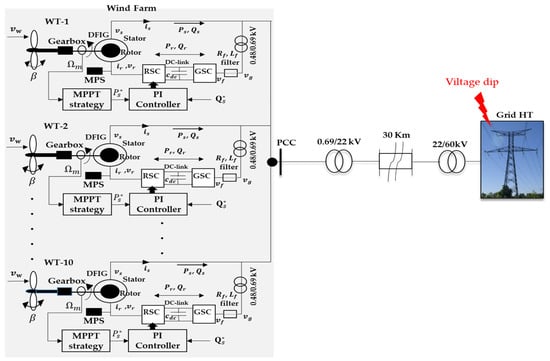
Figure 2.
Wind farm installation using DFIG.
2.1. Modeling the Turbines and the Approach for MPPT
The wind turbine model calculates the extracted mechanical power (Pcap) using the following equation:
St is the area swept by the turbine and ρ is the air mass density, respectively. The stall angle is denoted as β, while the speed ratio is represented by λ. The coefficient of power (Cp) and speed of wind (vw) are designated accordingly. In this paper, the coefficient of power model is formulated as in [6,28,29]:
By employing the DFIG, we can seize the peak wind power potential at the optimal tip speed (λopt), as illustrated in (4). Additionally, the mechanical speed controller of the generator utilizes the MPPT curve, as outlined in [28], and this utilization is determined by substituting (3) and (2) into (1).
When λ and β are kept at their optimal values, the maximum Cp value is achieved. As shown in Figure 3 below, Cp(λ,β) equals 0.48 when λopt is set to 8.1 and βopt to 0.
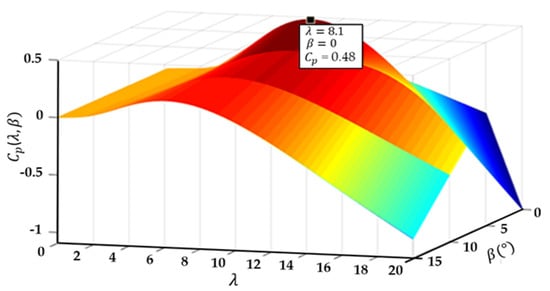
Figure 3.
Three-dimensional plot illustrating the Cp.
2.2. The Modeling of the DFIG and RSC Converter
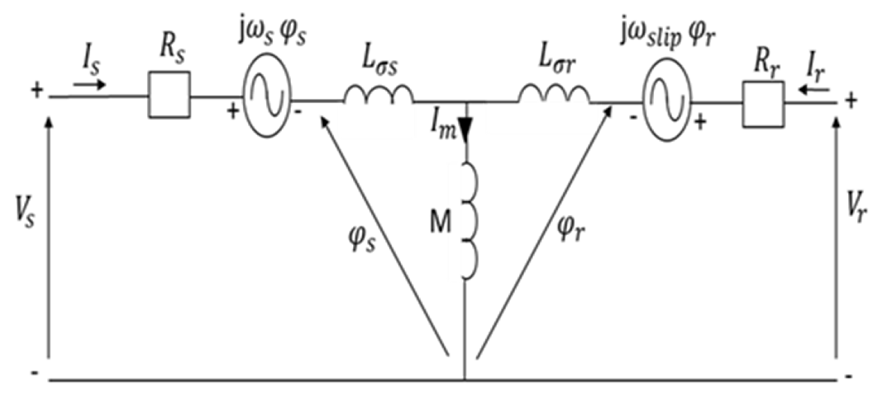
Equations (5)–(8), as outlined in [28,30] below, offer a means to record the stator and rotor voltages and fluxes. This is accomplished by applying both the DFIG-circuit model, as shown in Figure 4, and the reference synchronous frame, which is kept fixed relative to the stator flux level.
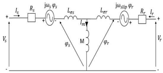
Figure 4.
The electrical model for the back-to-back converter circuit.
As depicted in Figure 2, Equations (9) and (10) [31] describe both the converter’s voltage and power (PS and QS) within the dq reference frame. These equations are defined with respect to the stator flux and the alternating current voltage of the network.
2.3. Design of the Controller for the DFIG-RSC System
The RSC can provide a variable steady-state frequency to the DFIG rotor, leading to changes in its rotational speed. Furthermore, the RSC dictates the provision of active and reactive output energy to the stator based on the dq current values of the rotor. As a result, the Equations mentioned above are transformed into the following expressions:
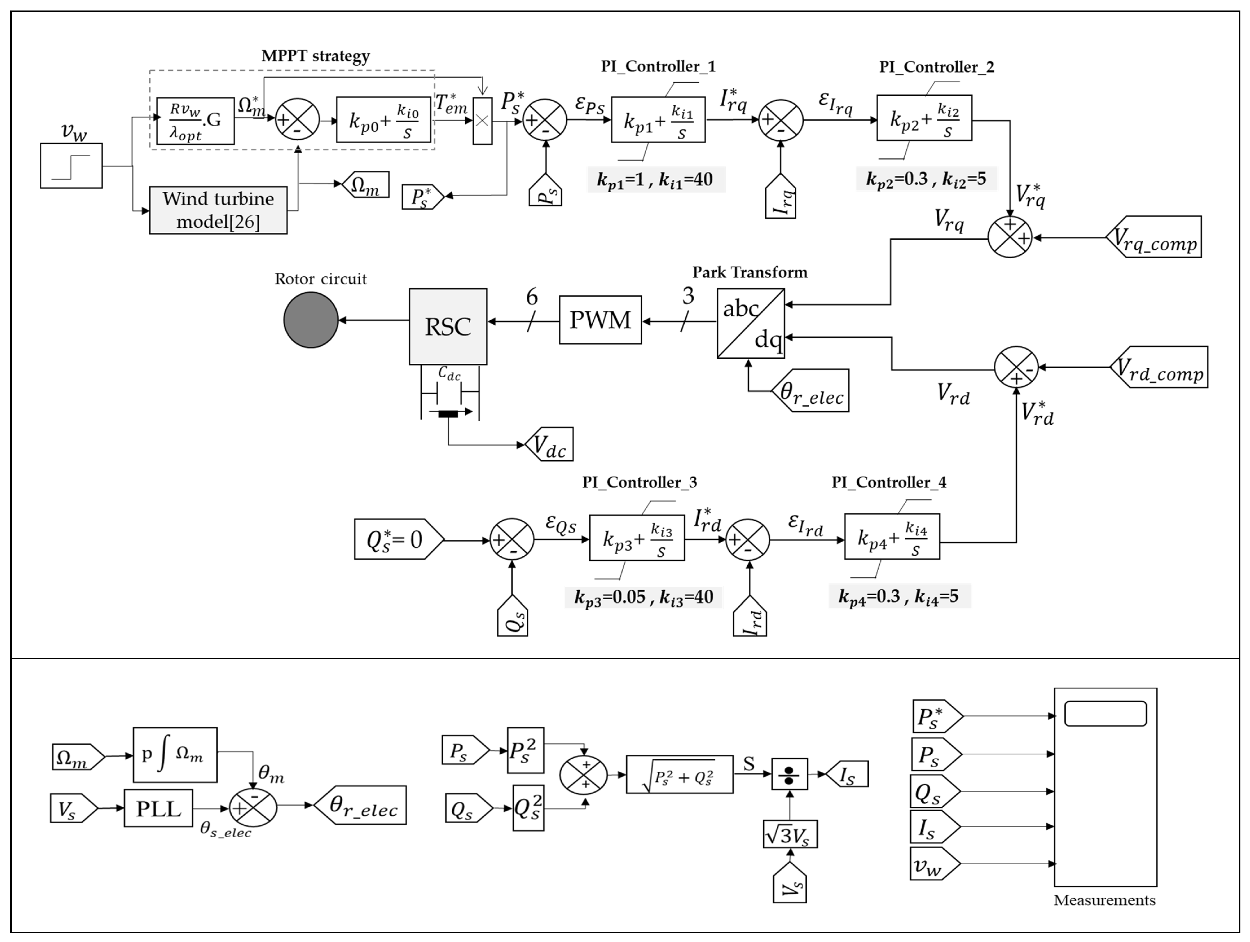
The expressions provided in Equations (11) and (12) can be derived to establish the relationship between the rotor’s dq current components and the stator power outputs Ps and Qs in the reference frame that is aligned with the static flux. In this specific application, the RSC is utilized for dual purposes: to control velocity (stator output power) and to monitor reactive energy (terminal voltage), as illustrated in Figure 5. To decouple the active and reactive power outputs from the stator using a rotor current command, the 3-phase instantaneous ir_abc was initially extracted and subsequently transformed into Ird and Irq through the utilization of a reference stator flux-oriented framework. To accomplish this, the references for Irq and Ird (denoted as I*rq and I*rd) are established through power controllers designed to control both the active and reactive output values, respectively. To calculate the actual error values, the real currents Ird and Irq are measured, and then, compared to their respective reference values. Subsequently, these measured error values are input into the PI regulators, which generate the command signals Vrq and Vrd. The related cross-coupling terms, Vrd_comp and Vrq_comp, are employed to rectify the two command voltage signals, leading to the determination of the resultant output magnitudes, Vrd and Vrq. The PWM unit delivers gate commands for IGBT to drive the RSC to process this output.

Figure 5.
Configuration of the RSC controller.
2.4. DFIG Operation during a Balanced Voltage Dip Event
A rapid decrease in stator tension, lowering it to a different level, results in a sudden increase in both the rotor current and the tension within the intermediate circuit DC-link. Although these surges are of brief duration, they can inflict harm on both the RSC and the DC capacitor in the linking circuit. This primarily arises from the converter’s insufficient capacity, rendering it incapable of generating the requisite voltage to manage the generator. Additionally, in Equation (13) [32,33], it illustrates the connection between the tension in both the stator and rotor:
In a stable state, where , Equation (13) transitions into Equation (14).
Upon the occurrence of a fault, a sudden alteration in the AC voltage (ΔVs) becomes evident. However, at the instant of the fault’s onset, the stator and rotor fluxes will not experience an abrupt change due to their definitions as = dt, and =, respectively. Considering Equation (13), the modification in this context will not be abrupt. As a result, when a fault arises, the fluctuation in stator voltage can be expressed using the following formulation:
To ensure remains at zero during the default state, a substantial step change (ΔVr) in the rotor voltage is necessary to match the alteration in stator voltage. However, due to the limited capacity of the RSC, it cannot produce the required ΔVr, as its maximum voltage capacity is only approximately 30%. Consequently, attempting to generate such a change in voltage would lead to a notable overcurrent in the rotor winding. This situation necessitates protective measures to prevent potential damage to the winding.
3. Protecting against an Overabundance of Rotor Current
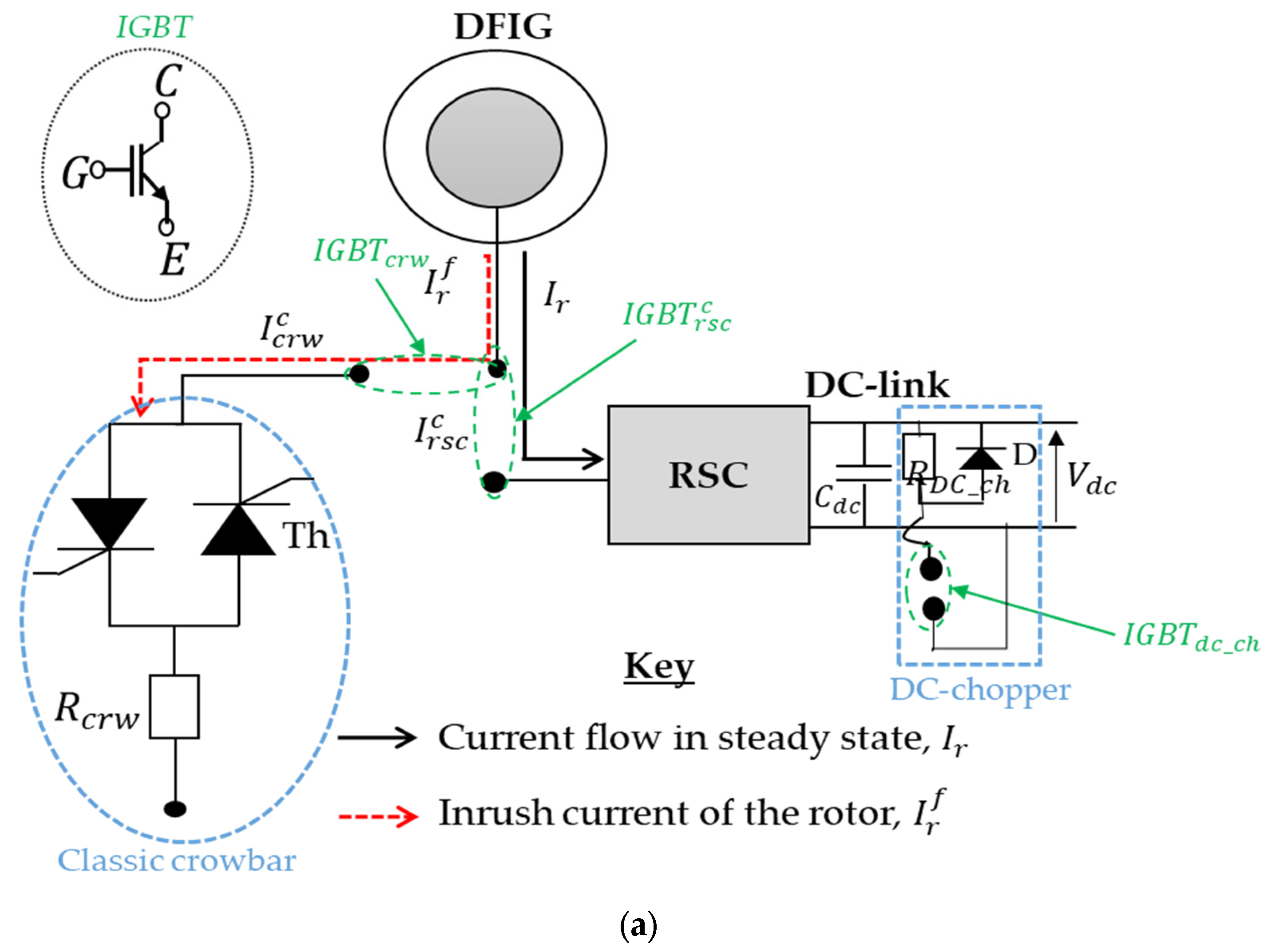
The subsequent section delineates the proposed modified protective scheme for rotor current in a DFIG. The crowbar (equipped with a DC-chopper) is the prevailing security apparatus in use for DFIG systems, designed to function in a specified timing sequence (as depicted in Figure 6a). Due to its high reliability, cost-effectiveness, and seamless integration, it stands as one of the favored approaches for mitigating surge currents in the rotor among various strategies. Nonetheless, activating the crowbar (IGBTcrw ON) during a grid failure prevents the RSC ( OFF) from operating, resulting in a total breakdown of generator control. In this scenario, the generator behaves akin to a squirrel-cage induction generator (SCIG), which operates with elevated resistance and encounters a pronounced slip, consequently generating a substantial requirement for reactive power. The increased need for reactive power depletes the tension level at the PCC.
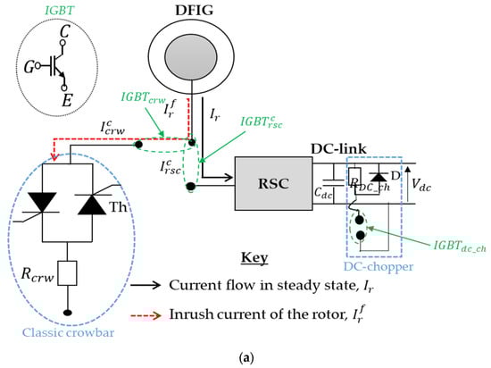
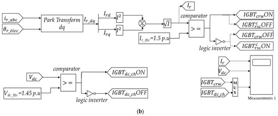
Figure 6.
Commutation configurations are depicted for (a) the conventional crowbar with DC-chopper arrangement and (b) the corresponding IGBT control algorithms.
Modified Protection Scheme
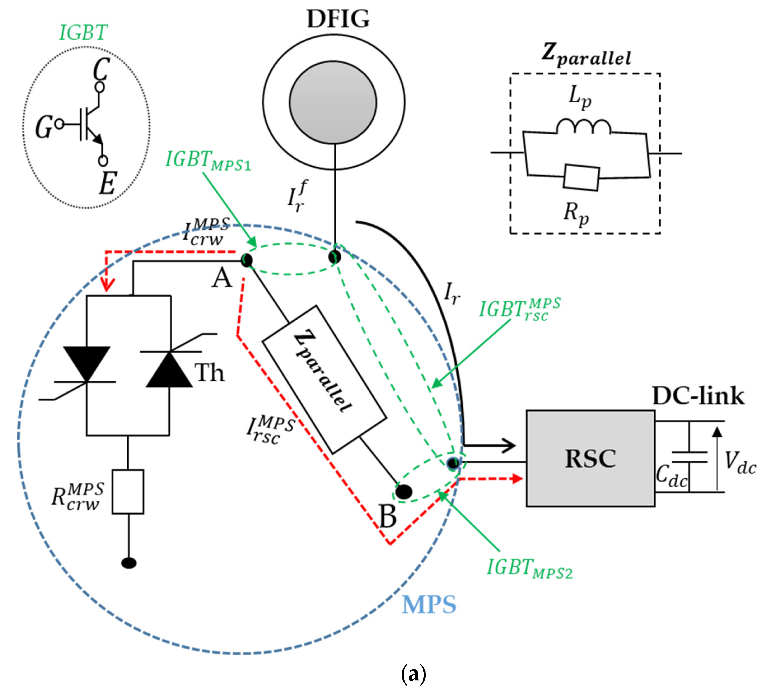
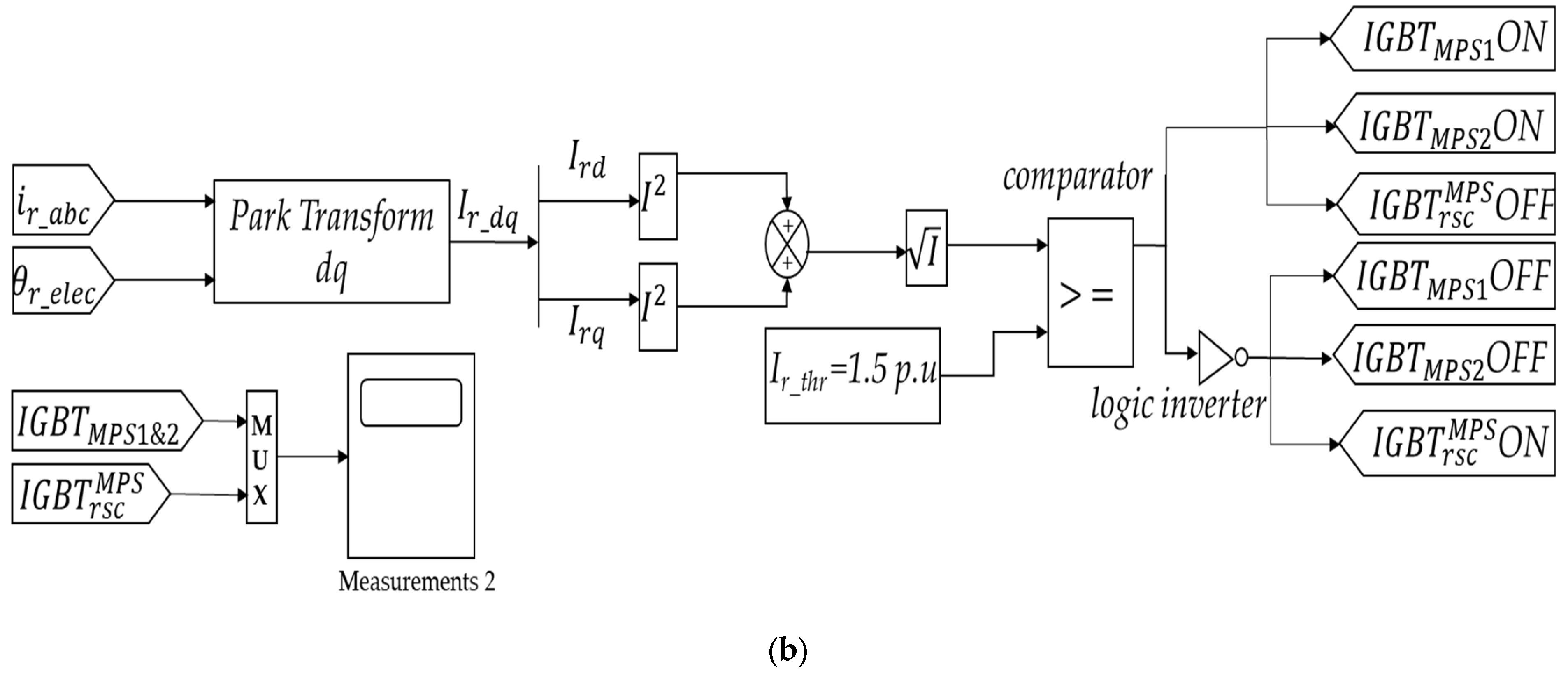
Figure 7a illustrates a schematic diagram of a recommended rotor current protection scheme designed to enhance the DFIG-LVRT’s performance during electric network disruptions. This involves the integration of both a crowbar and a component from the RpLp parallel circuit. In the event of the rotor current exceeding its maximum limit, the altered diagram is activated for the rotor windings at position A (IGBTMPS1 ON), and the RSC terminal is moved to position B (IGBTMPS2 ON).
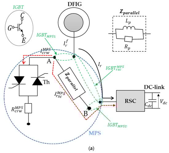

Figure 7.
Commutation configurations are depicted for (a) the modified protection scheme and (b) the corresponding IGBT control algorithms.
At this stage, the elevated rotor current () is apportioned between the crowbar current () and the current that flows through the RSC ().
The current level in the crowbar is determined by the value of the crowbar resistor (), while the current in the RSC is influenced by the impedance of the RpLp device (Zparallel).
Without factoring in the switching maneuvers during interruptions and fault clearance procedures, the RSC remains continuously connected to the rotor windings during the DFIG’s operation. Additionally, when the MPS is triggered, the generator’s rotor windings are separated, with one segment diverted through the crowbar and the other segment connected to the RSC. Retaining automatic control of the generator’s output through the RSC via a PI controller represents a notable advantage compared to the conventional crowbar (with a DC-chopper). Moreover, this protection scheme, involving the partial short-circuiting of rotor windings via the crowbar and their partial connection to the RSC through the RpLp circuit, creates a temporary operational mode for the generator. During this period, the machine demonstrates features reminiscent of both a wound-rotor induction generator and a squirrel-cage induction generator, thanks to the functioning of the MPS.
If we select a significant parallel impedance with (the resistance of the MPS crowbar) equal to the traditional crowbar resistance (), the MPS can assume the role of a standard crowbar. However, this outcome depends on the values of the RpLp parameters and the resistance of the MPS (). Conversely, when employing a low Zparallel and opting for a high crowbar resistance, the rotor’s overcurrent flows through the RpLp circuit towards the converter, potentially causing damage to the converter. Hence, it is necessary to uphold the correct parameters for Rp, and Lp in order to realize the intended objectives for the MPS.
4. Results from Simulations
The proposed techniques are explored and compared in this subsection with the help of compilation studies in a MATLAB/Simulink environment. One wind turbine of DFIG with both RSC and GSC physically spaced through the DC-link was connected to the electrical network modeled as a single two-mass unit, and the parameter values of the wind turbine and DFIG were found in [5,33] (Table 1).

Table 1.
Parameter values for the wind turbine and DFIG.
4.1. Results Pertaining to the Power Obtained
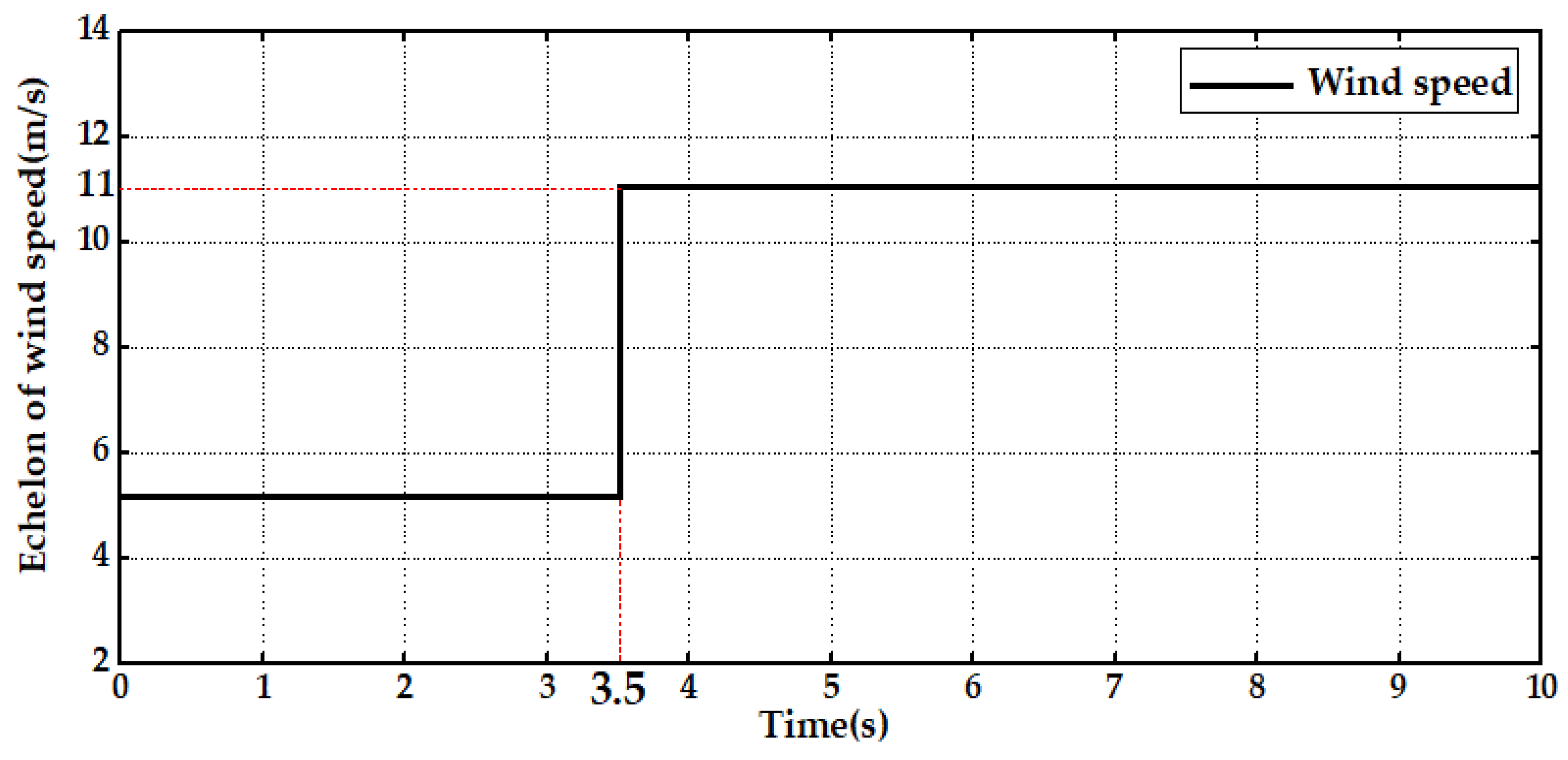
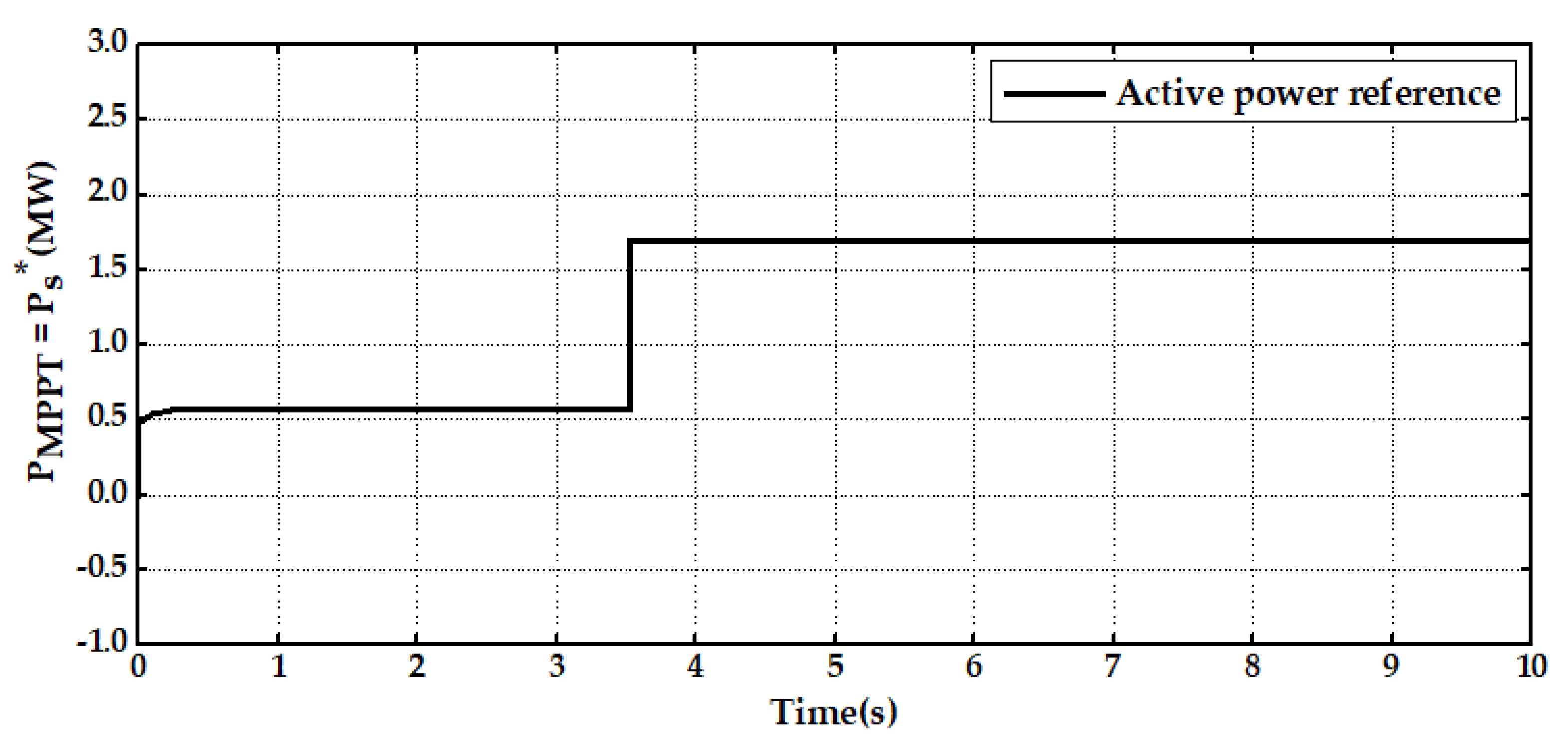
This study focused on wind farm operations using a DFIG. A wind profile modeled as a step change was used for analysis (shown in Figure 8). The simulation results are presented in the subsequent sections. The wind speed started at 5.1 m/s and rose to 11 m/s within 3.5 s. Figure 9 provides a visual representation of the changes in extracted power resulting from the employment of the MPPT strategy. This strategy utilizes a stator power reference and operates across various wind speeds. Notably, any influence from mechanical friction was excluded from this analysis.
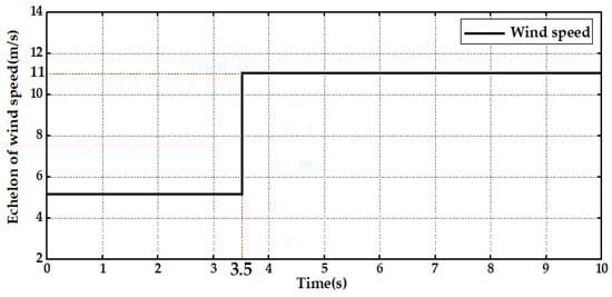
Figure 8.
Profile of wind speed.
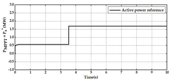
Figure 9.
Extracted power.
4.2. Results Obtained during the Comparison When a Balanced Voltage Dip Fault Is Present
At the time t = 7.5 s, a fault involving a balanced voltage dip emerged, originating at a location exceeding a distance of 30 km from the PCC. The fault persisted until t = 7.62 s (as depicted in Figure 10), at which point the issue was effectively resolved by isolating the malfunctioning section.
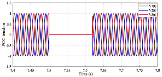
Figure 10.
Per unit (PU) voltage profile at the PCC.
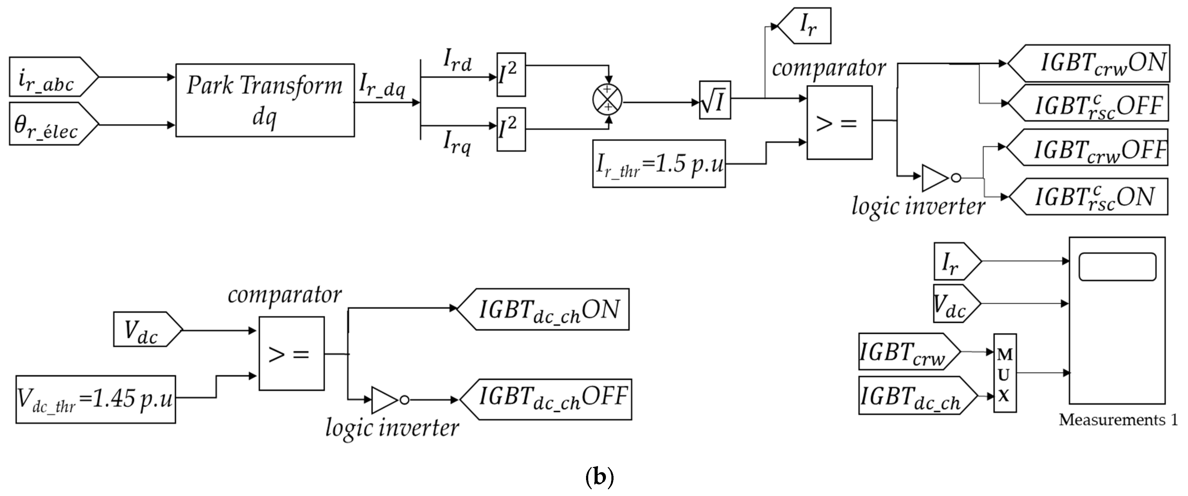
To demonstrate the validated responses for a 2 MW-DFIG unit, a comparison was conducted between two scenarios: one employing the conventional crowbar protection scheme with a DC-chopper, and the other utilizing the MPS. Therefore, a comparison was performed between these two distinct responses in the absence of any protection. To guarantee the activation of all protection schemes during critical failure scenarios, the threshold value for the rotor’s current limit was configured as Ir-thr = 1.5 pu (the maximum permissible value). The switching command diagram of the two protection schemes is shown in Figure 6b and Figure 7b. After conducting numerous simulation tests and employing a trial-and-error approach, the optimal values for the parameters ,, , Rp, and Lp were identified and are documented in Table 2.
Table 2.
Values of parameters for the traditional crowbar with DC-chopper and MPS.
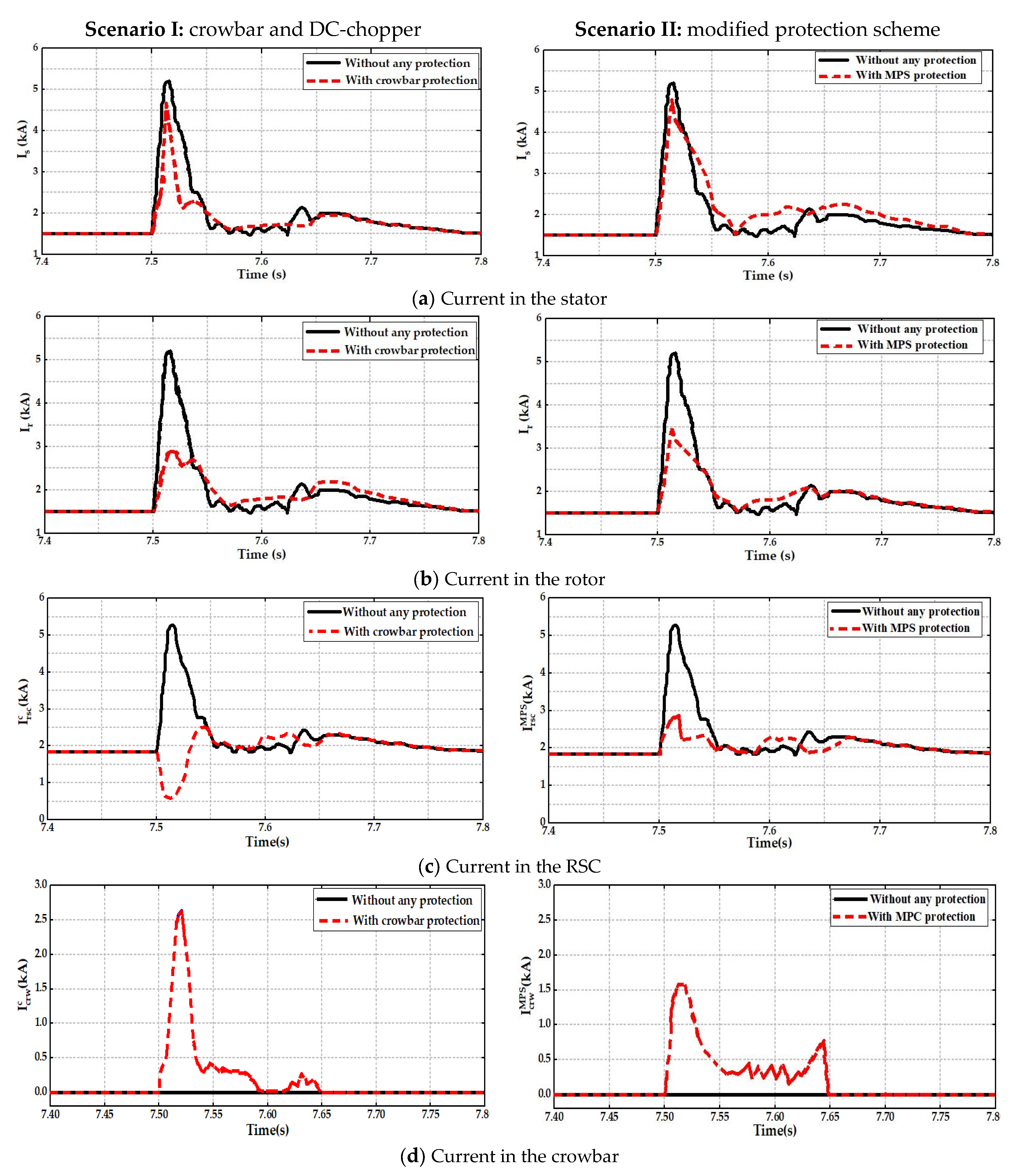
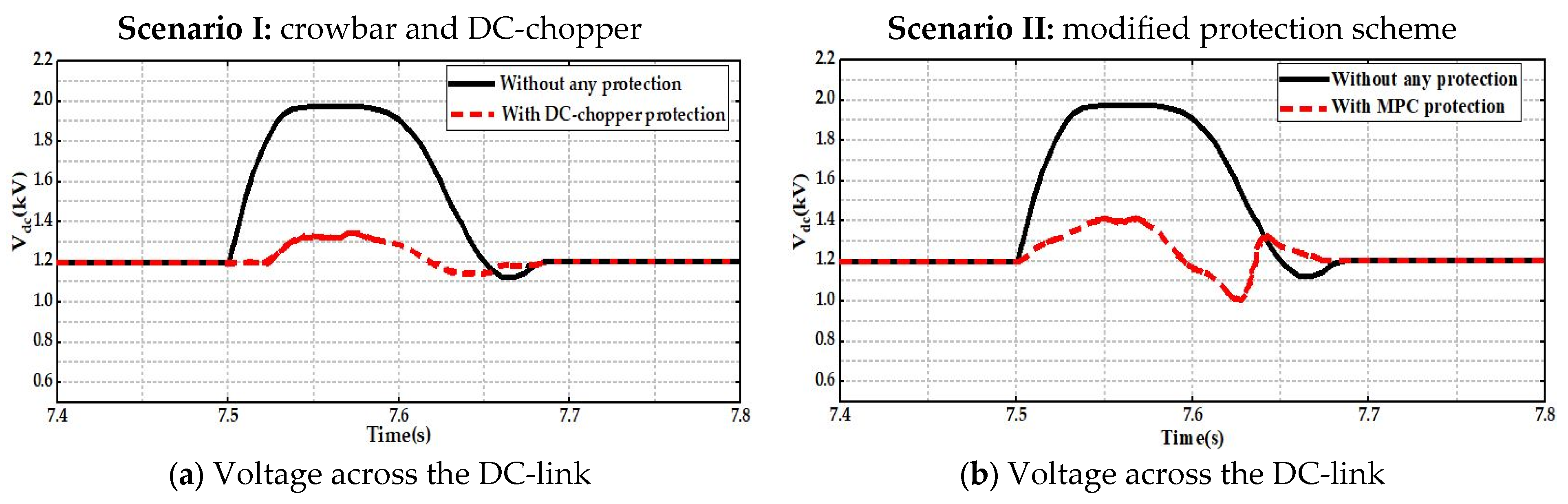
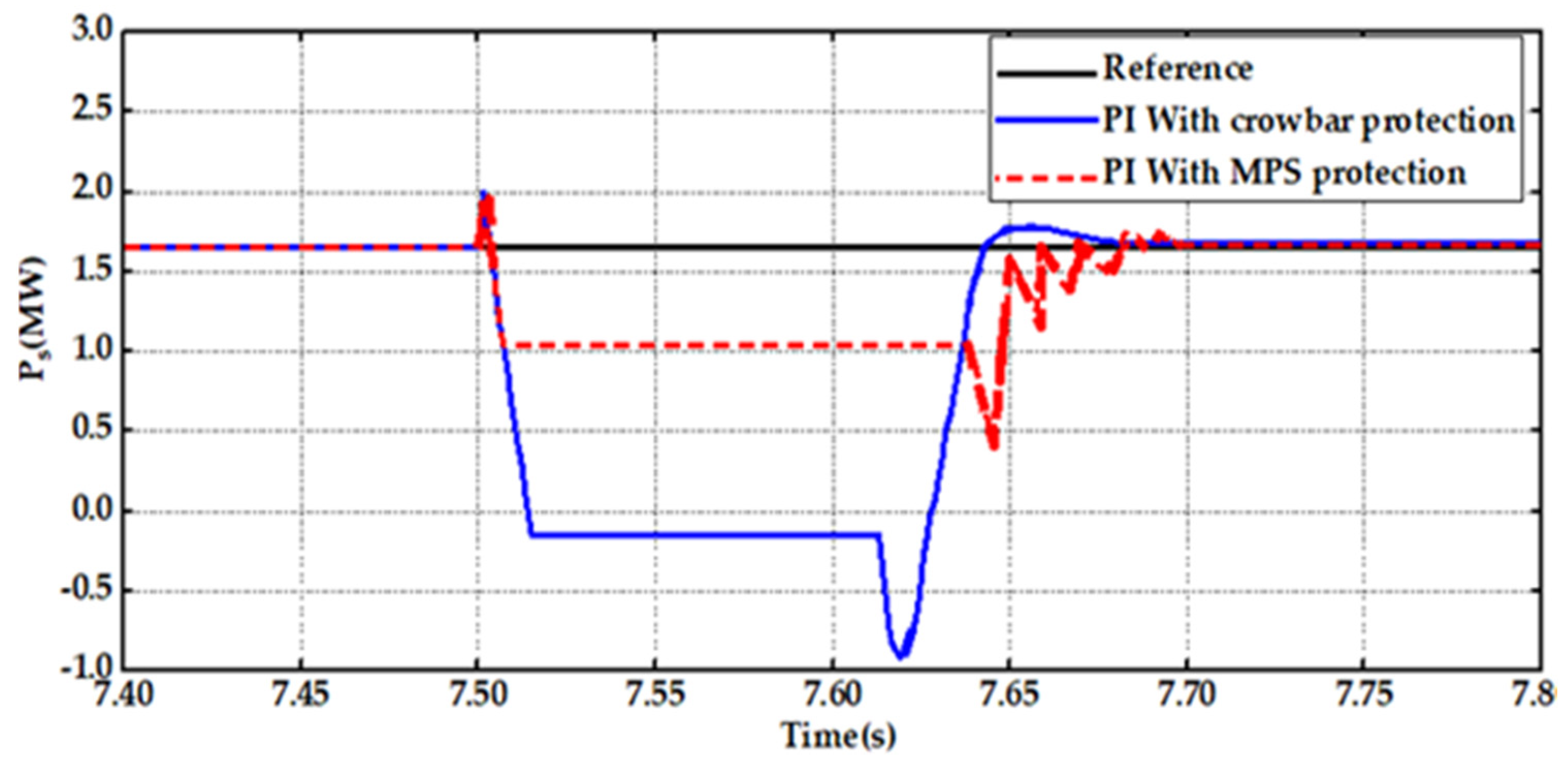
When no protective schemes are in place, both the stator and rotor currents (Figure 11a,b) exhibit similar characteristics. This similarity is a result of the strong electromagnetic coupling between the stator and rotor windings, which facilitates the transmission of the voltage dip’s effect on the stator current to the rotor. In Figure 11a, the stator current, observed under the incorporation of both protection schemes (scenarios I and II), remains inadequately regulated due to their sequential integration with the rotor windings, coupled with the magnetic interaction between the stator and rotor. Furthermore, it is worth noting that the stator current induces the generation of the rotor current through Faraday’s law of electromagnetic induction. Therefore, the protection schemes effectively confine only the rotor current to a considerable extent. The RMS stator current is approximately 5.2 kA without any protection measures. However, with the implementation of the traditional crowbar and MPS-enabled techniques, the RMS stator current decreases to 4.6 kA and 4.8 kA, respectively. Figure 11b, the RMS rotor current with no protection present is approximately 5.2 kA, while after the traditional crowbar and MPS are enabled, it is decreased to 2.9 kA and 3.1 kA, accordingly. Furthermore, with MPS, the RSC current reduces to below 2.9 kA instead of 0.2 KA with a crowbar, which demonstrates the keeping of the connection of RSC to the rotor, as seen in Figure 11c. In addition, when the MPS is used, its crowbar consumes 1.52 kA of rotor current against 2.52 kA with the standard crowbar, as illustrated in Figure 11d. It is important to emphasize that the primary purpose of employing this conventional crowbar in DFIG protection is to ensure the secure connection of the RSC to the rotor coils and swiftly dissipate the excess rotor current via the grounded resistor of the crowbar. With the MPS design, the goal is to keep the RSC attached to the coils of the rotor. The integrated crowbar of the MPS redirects excess current to the ground through its resistor. This mechanism absorbs a portion of the overcurrent in the rotor and assists in maintaining the RSC current within acceptable limits. Such safety tolerances exist in power electronics designs to manage transient conditions. For illustrative purposes, if the RSC threshold current were increased to twice its value (2 × 1.775 kA), the DFIG would be able to operate without any disconnection from the electric grid. Nonetheless, a significant drawback of the conventional crowbar method lies in the fact that the generator relinquishes control while the crowbar is activated. Through the implementation of the modified protection scheme (MPS), the necessity to deactivate the rotor-side converter (RSC) is effectively bypassed. This, in turn, results in improved performance of the DFIG-LVRT system. Maintaining safety is of paramount importance, and one key aspect in this regard is to ensure that the DC-link voltage remains within a secure range. Specifically, it is imperative to keep the DC-link voltage below the threshold of 1.45 per unit (pu) to prevent any potential risks or hazards. Figure 12 provides a clear visual representation of the DC-link voltage behavior. When no protective measures are in place, the DC-link voltage rises to 1.96 kV. However, with the implementation of the modified protection scheme (MPS), the peak voltage is effectively curbed at 1.4 kV. This stands in stark contrast to the conventional protection method, where the utilization of the DC-chopper (specifically, IGBTdc_ch ON) results in a significant reduction in the voltage to 0.3 kV. Therefore, the MPS demonstrates its capability to limit the DC-link voltage without necessitating the usage of a DC-chopper. Figure 13 shows a graphical representation of the dynamic response of the stator’s active power. This response is observed in the context of the PI controller. Initially, under the implementation of crowbar protection, the value of the parameter reaches 2 MW at the onset of the fault. Subsequently, it experiences a swift decline, dropping to a value below zero for the duration of the remaining fault period. Following the resolution of the fault, the parameter starts to rise again, accompanied by minor oscillations. Conversely, when the MPS is introduced, there is an enhancement in the dynamics of the active power, particularly throughout the fault period. The active power level attains 1.1 MW instead of the −0.1 MW observed with the implementation of a crowbar.
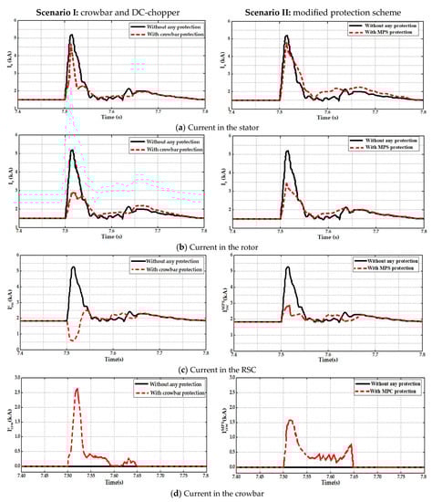
Figure 11.
Analyzing the outcomes when comparing two scenarios: Scenario I, which involves only the crowbar, and Scenario II, which incorporates the MPS for protection.
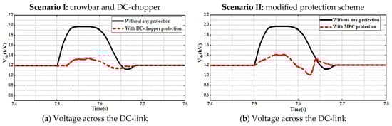
Figure 12.
Comparing the DC-link voltage outcomes between two scenarios: Scenario I, which involves solely the DC-chopper, and Scenario II, which includes the MPS for protection.
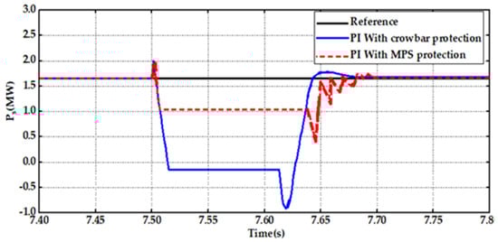
Figure 13.
Evaluating active power results for the stator using a PI controller in the context of two distinct protection schemes.
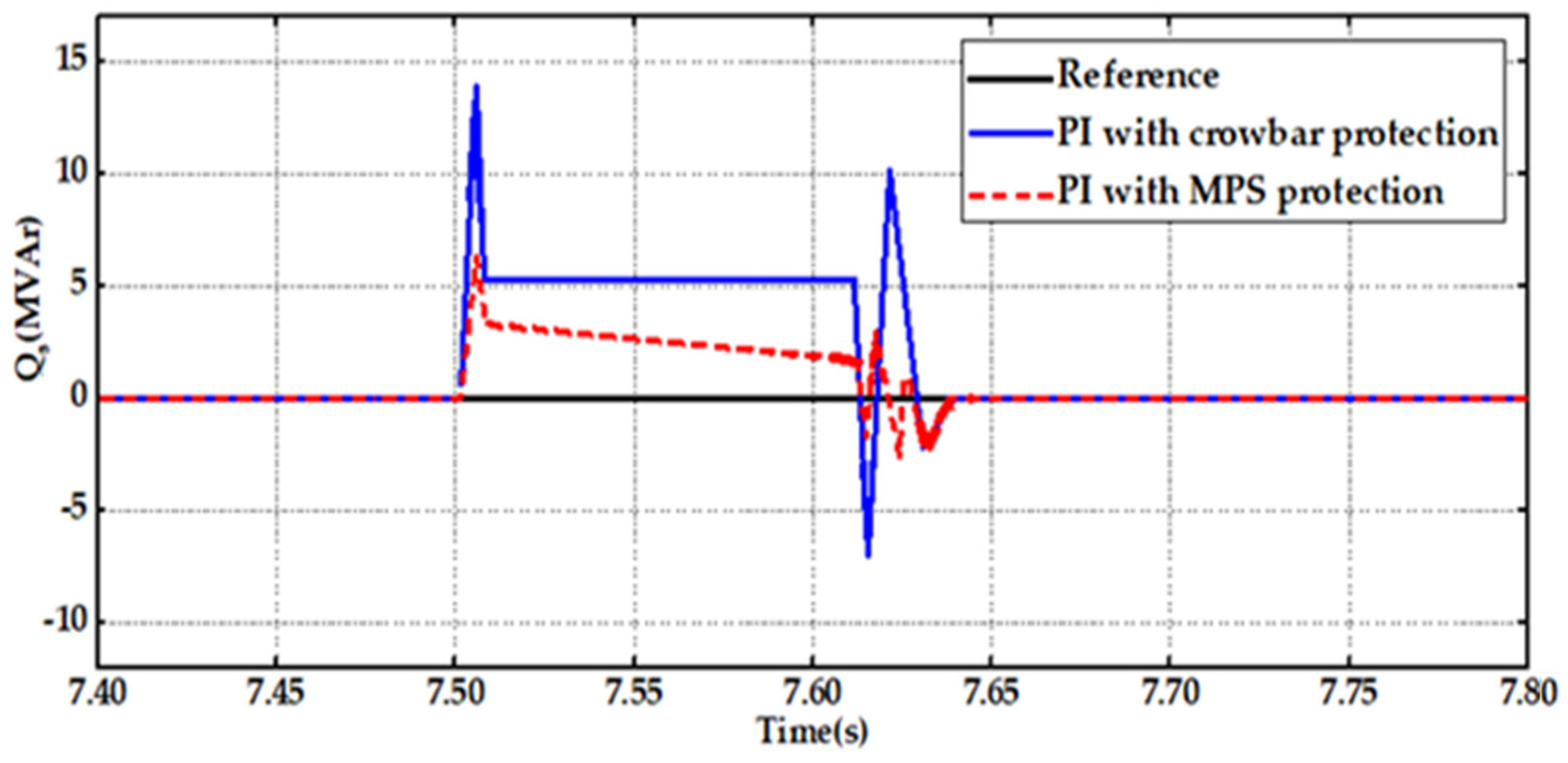
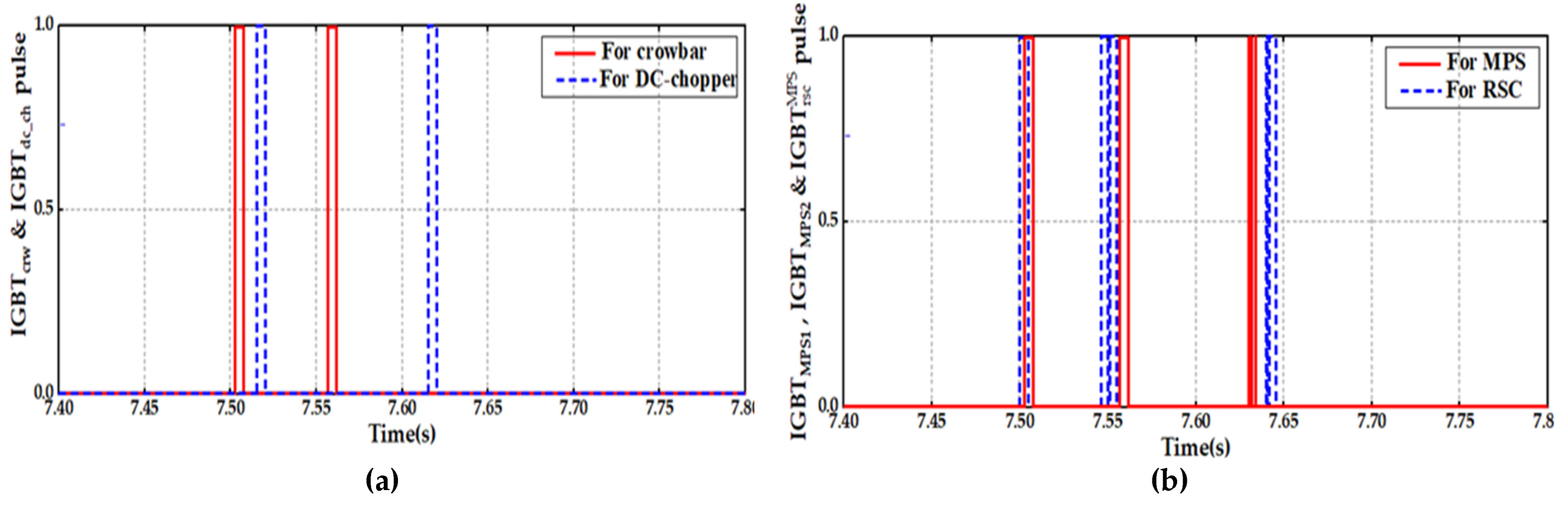
Figure 14 illustrates the dynamic behavior of the stator’s reactive power when controlled by the PI controller. Initially, under crowbar protection, the system requires a significant amount of reactive power from the grid upon the occurrence of a fault. Subsequently, this demand swiftly drops to 5 MVAr throughout the remainder of the fault period. After the fault is resolved, there is a notably pronounced oscillation in the reactive power. The second observation pertains to the utilization of MPS protection, which yields enhanced dynamics in the stator’s reactive power. Notably, during the fault, the reactive power value is mitigated to 1.5 MVAr. Subsequently, minimal oscillations occur post-fault clearance, contributing to elevated voltage levels at the PCC. This advantageous outcome ensures the sustained connection of the wind power system to the grid. In Figure 15a,b, the activation and inactivation pulses of the IGBTs are graphically depicted. These pulses indicate the moments when the IGBTs are turned on and turned off, allowing current to flow through them. This is a crucial aspect of the system’s operation as it defines the intervals when the IGBTs conduct electricity.
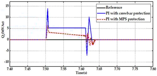
Figure 14.
Evaluating reactive power results for the stator using a PI controller in the context of two distinct protection schemes.
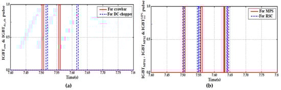
Figure 15.
Control signals of (a) IGBTcrw and IGBTdc_ch, and (b) IGBTMPS1, IGBTMPS2, and .
5. Conclusions
This research proposes an approach to enhancing the operational characteristics of wind farms that employ DFIGs when confronted with balanced voltage dips. The effectiveness of this solution is compared with the conventional crowbar protection system integrated with a DC-chopper. The proposed location for the MPS is directly situated behind both the rotor coils and the RSC converter during the installation process. It incorporates a traditional crowbar circuit and an RpLp circuit operating in parallel. In a manner akin to the crowbar, the MPS works to secure both the RSC and the DC-link capacitor, ensuring the RSC converter remains attached to the rotor and preventing any disruptions in generator control. When the MPS settings are finely tuned for the RpLp parallel device with an integrated crowbar, the DFIG operates in a hybrid mode, demonstrating qualities of both a semi-SCIG and a semi-DFIG. As a result, it is vital to exercise care when deciding on the settings in order to satisfy the needs of protective functions while preserving the functionality of the RSC. The comparative analysis undertaken reveals that the implementation of the MPS significantly augments the DFIG’s ability to withstand balanced voltage dips within the network. Furthermore, it effectively enhances the stator efficiency of the DFIG within wind energy systems when subjected to balanced voltage dips.
Author Contributions
Conceptualization, A.L., H.C., M.A.M. and A.B.B.; methodology, A.L., H.C., M.E.M. and A.B.B.; software, A.L., N.E. and A.H.; validation, A.L. and Z.M.S.E.; formal analysis, A.L., M.A.M., A.H. and M.A.M.; resources, A.L., H.C., M.E.M., N.E. and A.H.; data curation, A.L., H.C., M.E.M., N.E. and A.H.; writing—original draft preparation, A.L., M.A.M. and A.B.B.; writing—review and editing, A.L., H.C., M.E.M. and Z.M.S.E.; visualization, A.L., H.C., N.E. and A.H.; supervision, H.C. and Z.M.S.E.; project administration, H.C. and M.A.M.; funding acquisition, Z.M.S.E. All authors have read and agreed to the published version of the manuscript.
Funding
This research was funded by the Deanship of Scientific Research at King Khalid University through the General Research Project under Grant number (RGP.1/309/44).
Data Availability Statement
Not applicable.
Acknowledgments
The authors extend their appreciation to the Deanship of Scientific Research at King Khalid University for funding this work through the General Research Project under Grant number (RGP.1/309/44).
Conflicts of Interest
The authors declare no conflict of interest.
Abbreviations
| List of Notations | |
| Vs,Vr | Instantaneous stator and rotor voltages |
| Upcc | Common coupling point tension |
| Variation in stator voltage during a voltage dip | |
| Variation in rotor voltage during a voltage dip | |
| Is,Ir | Instantaneous stator and rotor currents |
| Ir-thr | Rotor current limit value during a voltage dip |
| Ps,Qs | Stator active and reactive power |
| Reference of stator active and reactive power | |
| S | Apparent power |
| θr_elec | Rotor electrical angle |
| θs_elec | Stator electrical angle |
| Reference electromagnetic torque | |
| Cdc | DC-link capacitance |
| Rf,Lf | Resistance and inductance of the filter |
| s,slip | Stator angular frequency, slip angular frequency |
| Mechanical speed | |
| p | Number of pole pairs |
| Wind speed | |
| Rp,Lp | Resistance and inductance of parallel impedance |
| Vsd,Vsq | Direct and quadrature stator voltage |
| Vrd,Vrq | Direct and quadrature rotor voltage |
| Ird,Irq | Direct and quadrature rotor current |
| Isd,Isq | Direct and quadrature stator current |
| Rcrw | Resistance of conventional crowbar |
| Resistance of MPS crowbar | |
| kp,ki | Controller constants |
| Acronyms | |
| WT | Wind turbine |
| WF | Wind farm |
| DFIG | Doubly fed induction generator |
| SCIG | Squirrel-cage induction generator |
| RSC | Rotor-side converter |
| GSC | Grid-side converter |
| AC | Alternating current |
| DC | Direct current |
| dq | Direct quadrature |
| PCC | Point of common coupling |
| MPPT | Maximum power point tracking |
| PWM | Pulse width modulation |
| PLL | Phase-locked loops |
| MUX | Multiplexer |
| LVRT | Low-voltage ride-through |
| FRT | Fault ride through |
| PI | Proportional–integral |
| Th | Thyristor |
| D | Diode |
| MPS | Modified protection scheme |
| IGBT | Insulated-gate bipolar transistor |
References
- Mossa, M. Modeling Analysis and Enhancement of the Performance of a Wind Driven DFIG During Steady State and Transient Conditions; Anchor Academic Publishing: Hamburg, Germany, 2014. [Google Scholar]
- Chetouani, E.; Errami, Y.; Obbadi, A.; Sahnoun, S. Design of Optimal Backstepping Control for a Wind Power Plant System Using the Adaptive Weighted Particle Swarm Optimization. Int. J. Intell. Eng. Syst. 2021, 14, 125–136. [Google Scholar]
- Saad, N.H.; Sattar, A.A.; Mansour, A.E.A.M. Low voltage ride through of doubly-fed induction generator connected to the grid using sliding mode control strategy. Renew. Energy 2015, 80, 583–594. [Google Scholar] [CrossRef]
- Li, S.; Haskew, T.A.; Williams, K.A.; Swatloski, R.P. Control of DFIG wind turbine with direct-current vector control configuration. IEEE Trans. Sustain. Energy 2012, 3, 1–11. [Google Scholar] [CrossRef]
- Rached, B.; Elharoussi, M.; Abdelmounim, E. Fuzzy logic control for wind energy conversion system based on DFIG. In Proceedings of the 2019 International Conference on Wireless Technologies, Embedded and Intelligent Systems (WITS), Fez, Morocco, 3–4 April 2019; pp. 1–6. [Google Scholar]
- Beltran, B.; Ahmed-Ali, T.; Benbouzid, M.E.H. Sliding mode power control of variable-speed wind energy conversion systems. IEEE Trans. Energy Convers. 2008, 23, 551–558. [Google Scholar] [CrossRef]
- Mwasilu, F.; Justo, J.J.; Ro, K.-S.; Jung, J.-W. Improvement of dynamic performance of doubly fed induction generator-based wind turbine power system under an unbalanced grid voltage condition. IET Renew. Power. Gener. 2012, 6, 424–434. [Google Scholar] [CrossRef]
- Qin, B.; Li, H.; Zhou, X.; Li, J.; Liu, W. Low-voltage ride-through techniques in DFIG-based wind turbines: A review. Appl. Sci. 2020, 10, 2154. [Google Scholar] [CrossRef]
- Akanto, J.M.; Hazari, M.R.; Mannan, M.A. Lvrt and stability enhancement of grid-tied wind farm using dfig-based wind turbine. Appl. Syst. Innov. 2021, 4, 33. [Google Scholar] [CrossRef]
- Yamparala, S.; Lakshminarasimman, L.; Rao, G.S. Improvement of LVRT Capability for DFIG based WECS by Optimal Design of FoPID Controller using SLnO + GWO Algorithm. Int. J. Intell. Eng. Syst. 2023, 16, 202–213. [Google Scholar]
- Loulijat, A.; Ababssi, N.; Makhad, M. Kalman Observer Contribution to a Second Order Sliding Mode Control for Wind Turbine Based on DFIG During the Network Voltage Dip. Int. J. Intell. Eng. Syst. 2021, 14, 88–101. [Google Scholar] [CrossRef]
- Okedu, K.E.; Member, S.; Muyeen, S.M.; Takahashi, R.; Tamura, J.; Member, S. Wind farms fault ride through using DFIG with new protection scheme. IEEE Trans. Sustain. Energy 2012, 3, 242–254. [Google Scholar] [CrossRef]
- Yang, J.; Fletcher, J.E.; O’Reilly, J. A series-dynamic-resistor-based converter protection scheme for doubly-fed induction generator during various fault conditions. IEEE Trans. Energy Convers. 2010, 25, 422–432. [Google Scholar] [CrossRef]
- Rahimi, M.; Parniani, M. Low voltage ride-through capability improvement of DFIG-based wind turbines under unbalanced voltage dips. Int. J. Electr. Power Energy Syst. 2014, 60, 82–95. [Google Scholar] [CrossRef]
- Mohammadi, J.; Afsharnia, S.; Ebrahimzadeh, E.; Blaabjerg, F. An Enhanced LVRT Scheme for DFIG-based WECSs under Both Balanced and Unbalanced Grid Voltage Sags. Electr. Power Compon. Syst. 2017, 45, 1242–1252. [Google Scholar] [CrossRef]
- Pannell, G.; Zahawi, B.; Atkinson, D.J.; Missailidis, P. Evaluation of the performance of a DC-link brake chopper as a DFIG low-voltage fault-ride-through device. IEEE Trans. Energy Convers. 2013, 28, 535–542. [Google Scholar] [CrossRef]
- Yang, S.; Zhou, T.; Sun, D.; Xie, Z.; Zhang, X. A SCR crowbar commutated with power converter for DFIG-based wind turbines. Int. J. Electr. Power Energy Syst. 2016, 81, 87–103. [Google Scholar] [CrossRef]
- Noureldeen, O. Behavior of DFIG Wind Turbines with Crowbar Protection under Short Circuit. Int. J. Electr. Comput. Sci. IJECS-IJENS 2012, 12, 129103–136868. [Google Scholar]
- Adekanle, O.S.; Guisser, M.; Abdelmounim, E.; Aboulfatah, M. Nonlinear Controller with Rotor Crowbar and DC-Chopper Fault Ride Through Technique for Grid-Connected Doubly-Fed Induction Generator. Int. Rev. Autom. Contr. 2018, 11, 281–292. [Google Scholar] [CrossRef]
- Saeed, S.; Asghar, R.; Mehmood, F.; Saleem, H.; Azeem, B.; Ullah, Z. Evaluating a Hybrid Circuit Topology for Fault-Ride through in DFIG-Based Wind Turbines. Sensors 2022, 22, 9314. [Google Scholar] [CrossRef]
- Sharma, R.; Makwana, V.H. An advanced LVRT controlled DSCC-STATCOM for reactive power compensation. Int. J. Power Electron. Drive Syst. 2023, 14, 294–303. [Google Scholar] [CrossRef]
- López, J.; Gubía, E.; Olea, E.; Ruiz, J.; Marroyo, L. Ride through of wind turbines with doubly fed induction generator under symmetrical voltage dips. IEEE Trans. Ind. Electron. 2009, 56, 4246–4254. [Google Scholar] [CrossRef]
- Qiao, W.; Venayagamoorthy, G.K.; Harley, R.G. Real-time implementation of a STATCOM on a wind farm equipped with doubly fed induction generators. IEEE Trans. Ind. Appl. 2009, 45, 98–107. [Google Scholar] [CrossRef]
- Liang, J.; Qiao, W.; Harley, R.G. Feed-forward transient current control for low-voltage ride-through enhancement of DFIG wind turbines. IEEE Trans. Energy Convers. 2010, 25, 836–843. [Google Scholar] [CrossRef]
- Wessels, C.; Member, S.; Gebhardt, F.; Member, S.; Fuchs, F.W.; Member, S. Fault Ride-Through of a DFIG Wind Turbine Using a Dynamic Voltage Restorer During Symmetrical and Asymmetrical Grid Faults. IEEE Trans. Power Electron. 2011, 26, 807–815. [Google Scholar] [CrossRef]
- Qin, K.; Wang, S.; Kang, Z. Research on zero-voltage ride through control strategy of doubly fed wind turbine. Energies 2021, 14, 2287. [Google Scholar] [CrossRef]
- Reddy, K.; Saha, A.K. A Heuristic Approach to Optimal Crowbar Setting and Low Voltage Ride through of a Doubly Fed Induction Generator. Energies 2022, 15, 9307. [Google Scholar] [CrossRef]
- Chojaa, H.; Derouich, A.; Chehaidia, S.; Zamzoum, O.; Taoussi, M.; Benbouhenni, H.; Mahfoud, S. Enhancement of Direct Power Control by Using Artificial Neural Network for a Doubly Fed Induction Generator-Based WECS: An Experimental Validation. Electronics 2022, 11, 4106. [Google Scholar]
- Sobhy, A.; Abo-Khalil, A.G.; Lei, D.; Salameh, T.; Merabet, A.; Alkasrawi, M. Coupling DFIG-Based Wind Turbines with the Grid under Voltage Imbalance Conditions. Sustainability 2022, 14, 5076. [Google Scholar] [CrossRef]
- Ngom, I.; Mboup, A.B.; Thiaw, L.; Skander-Mustapha, S.; Belkhodja, I.S. An improved control for DC-link fluctuation during voltage dip based on DFIG. In Proceedings of the 2018 9th International Renewable Energy Congress (IREC), Hammamet, Tunisia, 20–22 March 2018; pp. 1–6. [Google Scholar]
- Meegahapola, L.G.; Littler, T.; Flynn, D. Decoupled-DFIG Fault Ride-Through Strategy for Enhanced Stability Performance During Grid Faults. IEEE Trans. Sustain. Energy 2010, 1, 152–162. [Google Scholar] [CrossRef]
- Foster, S.; Xu, L.; Fox, B. Coordinated reactive power control for facilitating fault ride through of doubly fed induction generator-and fixed speed induction generator-based wind farms. IET Renew. Power Gener. 2010, 4, 128–138. [Google Scholar] [CrossRef]
- Loulijat, A.; Chojaa, H.; El Marghichi, M.; Ettalabi, N.; Hilali, A.; Mouradi, A.; Abdelaziz, A.Y.; Elbarbary, Z.M.S.; Mossa, M.A. Enhancement of LVRT Ability of DFIG Wind Turbine by an Improved Protection Scheme with a Modified Advanced Nonlinear Control Loop. Processes 2023, 11, 1417. [Google Scholar] [CrossRef]


Disclaimer/Publisher’s Note: The statements, opinions and data contained in all publications are solely those of the individual author(s) and contributor(s) and not of MDPI and/or the editor(s). MDPI and/or the editor(s) disclaim responsibility for any injury to people or property resulting from any ideas, methods, instructions or products referred to in the content. |
© 2023 by the authors. Licensee MDPI, Basel, Switzerland. This article is an open access article distributed under the terms and conditions of the Creative Commons Attribution (CC BY) license (https://creativecommons.org/licenses/by/4.0/).