3.1. The Influence of Jet Angle on the Isolation Pressure Difference
As one of the main factors affecting the efficiency of a multi-machine parallel circulation air curtain, the jet air supply angle directly determines the strength of its air flow ability to partition a roadway [
25]. When an air curtain works to isolate the air flow of a roadway, the static pressure difference generated before and after it is called the effective pressure of the air curtain, that is, the partition pressure difference of the air curtain [
26]. This indicator can directly reflect the barrier capacity of the air curtain. The simulation is divided into five parts, which are the numerical simulation of different jet angles under the full pressure of the fan blade at 20°, 25°, 30°, 35°, and 40°, from which the relationship between the full pressure of the fan and the pressure difference of the separator can be judged. The jet angle at each fan blade angle is set to 5°, 15°, 30°, 45°, and 60°. The outlet width is set to 0.16 m, and the outlet height is 1.7 m. The simulation results of different jet angles under different full pressures of different fans are analyzed and compared by intercepting Y = 0.86 m sections.
Figure 7,
Figure 8 and
Figure 9 show pressure clouds of the fan blade angles of the air curtain at 20°, 25°, and 30° and the jet working at different angles. It can be seen that under the action of the air curtain, the pressure distribution of the roadway undergoes a very obvious change. The roadway pressure cloud map where the air curtain is located can be divided into three parts, namely, the chamber position and upstream and downstream of the roadway wind flow. As shown in the figure, it can be seen that the upstream position of the roadway is green, and the downstream is light blue. This is due to the action of the air curtain, which causes the pressure upstream of the roadway wind flow to be significantly greater than that downstream of the roadway, resulting in a partition pressure difference.
The blue area at the chamber location is significantly deeper than downstream of the roadway, and the pressure is negative. This is due to the rotation of the fan blades of the air curtain fan, which extracts the roadway air, and the inhaled air flow is ejected through the air supply to form a high-speed jet. And because of the influence of the lateral pressure from the roadway wind flow, the jet bends and shifts, and flows downstream of the roadway air flow, so that the air flow forms a circulation between the inlet and outlet of the air curtain.
It can also be seen from
Figure 7,
Figure 8 and
Figure 9 that when the air curtain is 5°, 15°, and 30°, the jets ejected by the air curtain on both sides of the chamber position collide and merge in the middle of the roadway, forming a closed air curtain, and the ability to resist the roadway wind flow is strong. When the jet angle is 45° and 60°, the blue color of the chamber position is lighter, indicating that the local negative pressure formed is small, and the jets ejected by the air curtains on both sides also collide in the middle of the roadway.
From
Figure 10 and
Figure 11, it can be seen that the color of the chamber position is close to downstream of the roadway wind flow, and there is no obvious difference. This shows that there is no circulating air flow between the inlet and outlet of the air curtain on both sides of the chamber, that basically no completely closed air curtain is formed, and that the effect of isolating the air flow of the roadway is not exerted. Comparing the results of the same angle in
Figure 7,
Figure 8 and
Figure 9 shows that when the fan blade angle of the air curtain fan is 35° and 40°, the working nature changes, and the air curtain may show the phenomenon of excessive partition, which needs to be further analyzed and determined from the specific data.
Since the model adopts a large-section roadway, the pressure of each Y axial height plane is close to but not exactly the same under the action of the air curtain and the roadway wind flow. The jet of the air curtain collides with the roadway wind flow, and a vortex will be formed locally, resulting in large changes in wind flow disturbance, and the position where the wind flow disturbance changes greatly. It is necessary to avoid the position where the wind flow disturbance changes greatly.
According to the relationship between power, pressure difference, and air volume, combined with the above simulation data, it can be calculated that under the conditions of different fan full pressure and different jet angles, the effective power generated by the air curtain is between 840.8 and 2043.3 W. The result of calculating the isolation pressure difference is shown in
Figure 12.
As can be seen from
Figure 12, the size of the isolation pressure difference depends on two variables: one is the angle and the other is the full pressure of the fan. When the full pressure of the air curtain fan is at a blade angle of 20°, when the jet is shot out at different angles, the overall isolation pressure difference is small. At a jet angle of 5°, the isolation pressure difference reaches 36 Pa. As the angle increases to 15°, the rate of differential isolation pressure rises steeper. When the jet angle reaches 30°, the isolation pressure difference reaches the maximum, but the upward trend between 15° and 30° is smoother than the upward trend of 5~15°. At the jet angle of 45°, the isolation pressure difference drops very significantly. As the jet angle continues to increase to 60°, the isolation pressure difference continues to fall, and the rate of decline is reduced compared with the previous section when the isolation pressure difference reaches the minimum value. By analyzing the polyline when the fan blade is 25°, 30°, 35°, and 40°, it can be found that it has the same change law as described above. When the jet angle is fixed, with the increase in the full pressure of the fan, the partition pressure difference also continues to increase, showing a positive correlation. This law is the same in the jet angle of 5~60°, indicating that the ability of the multi-machine parallel circulating air curtain to isolate the air flow of the roadway is enhanced with the increase in the full pressure of the fan. Since the jet angle is in the range of 15~30°, the rate of increase in the isolation pressure difference is gentler than that of the previous section and basically reaches the maximum value.
This shows that the optimal jet angle range of the multi-machine parallel circulation air curtain is 15~30°. When the angle is greater than 30°, the isolation pressure difference drops sharply. When the angle increases to 45°, the isolation pressure difference continues to decrease, but the angle has less effect on the isolation pressure difference.
When the jet angle is greater than 30°, two jets erupt from the air curtain outlet. Sufficient air is not sucked up in a relatively short time, and the boundaries and sections of the jet are not sufficiently enlarged to a certain extent. Under the action of the lateral pressure of the roadway wind flow, it bends and flows downstream of the roadway wind flow, so that the two jets do not collide to form a wind curtain or the formed wind curtain is not completely closed. The air curtain is not completely intercepted, resulting in some roadway air flow through, resulting in a certain degree of air leakage, resulting in a small partition pressure difference.
3.2. The Influence of Jet Angle on Air Leakage Volume and Wind Choke Rate
In order to explore the influence of the jet angle of the air curtain on the wind flow of the partition roadway, the velocity cloud and velocity vector plot of the jet ejected at each angle when the full pressure of the fan is 25° are listed below. Due to the large number of models, the specific situation of wind turbine blade angles of 20°, 30°, 35°, and 40° is represented in
Figure 13.
The inlet wind speed of the roadway is 4 m/s, and the total air volume is 58.8 m
3/s. When the air curtain is closed, because the cross-sectional area of the two roadways is the same, the natural distribution of the components of both roadways in the parallel wind network is 29.4 m
3/s, that is, the wind speed is equal to 2 m/s. It is clear from the velocity cloud plots in
Figure 13,
Figure 14,
Figure 15,
Figure 16 and
Figure 17 that the color difference between the two roadways is large. The color of the roadway with the air curtain is dark, and the display speed is about 0.0~1.0 m/s. The roadway without the air curtain is lighter in color, and the speed is displayed at 3.0~4.0 m/s. This shows that under the action of the multi-machine parallel circulation air curtain, some roadway air flow is effectively intercepted and plays a significant role.
Figure 13 shows a clear high-speed wind flow passing between the two jets because the air curtain on both sides of the roadway is at 5°. The jets ejected at 5° are close to the roadway wall, so the jets will rub against the roadway wall, and the friction position will form a vortex, which has a more obvious wall effect. In the case of a certain amount of jet flow, as the jet ejected from the outlet moves forward and continuously sucks the air in the roadway, the momentum of the jet gradually decreases, and after reaching a certain distance, the momentum decreases to 0. However, at this time, the two jets of the air curtain have not collided and merged in the middle of the roadway to form a closed air curtain, more roadway wind flows through, and the air leakage is large, so the ability to intercept the roadway wind flow is poor.
From
Figure 14,
Figure 15 and
Figure 16, it can be found that when the jet angle is 15°, 30°, and 45°, a circulating air flow is formed between the air curtain outlet and the inlet at the chamber position, and the colors of the upper and lower reaches of the roadway in the velocity cloud diagram are close to the same, indicating that the effect of intercepting the roadway wind flow is better. In
Figure 15, when the jet angle is 30°, the wind velocity distribution at the chamber position is the most uniform, the wind curtain formed is the most complete, and the wind flow disorder is good. It can be seen from
Figure 17 that due to the excessive angle of the jet, after the jet is ejected and before the air flow is sucked up enough to further convert the momentum, it is subjected to lateral pressure from the roadway wind flow, resulting in bending and shifting. The two jets cannot collide and merge in the middle of the roadway, so more roadway wind flows through, the air leakage is large, and the ability to intercept the roadway wind flow is very poor.
In order to accurately judge the air leakage volume and wind choke rate at various angles, we obtain the change trend between 5° and 60° and the angle interval with the best effect of isolating the roadway wind flow, intercept the roadway section 20 m downstream of the chamber, and use Fluent to calculate the average air volume of the entire section as the air leakage volume. Then, we subtract the air leakage from the original total air volume of the roadway to be the air volume intercepted by the air curtain and then divide it by the total air volume of the roadway to determine the wind choke rate at various angles. The calculation results are shown in
Figure 17 and
Figure 18.
As shown in
Figure 18, it can be seen that there are positive and negative values in the air leakage volume. Positive values indicate that the air curtain is not intercepted by the roadway wind flow, whereas negative values mean that the partition is excessive, no roadway air flow passes through the air curtain, and the function of the air curtain is no longer a barrier. According to the positive and negative air leakage volume, the diagram can be divided into two parts: upper and lower. When the fan blade angle is 30° and the jet angle is 30°, the air leakage at this time is minimal, and only 2.5 m
3/s of roadway wind flow is not intercepted. When the jet angle is 45°, the air leakage increases to 4.8 m
3/s, and the partition capacity deteriorates significantly. When the jet angle continues to increase to 60°, the air leakage reaches a maximum of 6.8 m
3/s. At this time, the ability of the multi-machine parallel circulating air curtain to isolate the roadway air flow is the worst, the rate of air leakage increase at 45~60° is significantly faster than that at 30~45°, and the slope becomes steeper, as intuitively reflected in
Figure 18. It shows that when the jet angle reaches 45° and continues to increase, the blocking capacity will be sharply reduced.
When the jet angle is 5~15°, the air leakage volume is negative. At this time, the section of the roadway taken for the leakage air volume not only does not have the wind flow from upstream of the roadway but the air volume downstream of the roadway is led upstream under the action of the air curtain, resulting in the reverse wind phenomenon. This shows that the isolation effect of the multi-machine parallel air curtain has reached its best when the full pressure of the fan is 30°, and reducing the angle will make the air curtain lose its ability to block the air flow in the roadway and start to drain the air flow.
When the fan blade angles are 20° and 25°, respectively, the air leakage volume in the range of 5~60° is positive, indicating that there is air leakage at any angle, and the air curtain is blocking the air flow. When the jet angle is 5~15°, the air leakage volume is significantly reduced. In the angle range of 15~30°, the air leakage volume still continues to decrease, and the decline rate begins to slow down compared with the rate of the previous angle range, indicating that the air curtain isolation capacity increases in this angle range and gradually approaches the optimal angle. When the jet angle increases to 30~45°, the air leakage volume begins to increase at a faster rate, and the isolation capacity decreases rapidly. When the angle increases to 60°, the air leakage volume increases to the maximum value at the full pressure of the corresponding fan, and the isolation capacity is the worst. When the fan blade angle is 35° and 40°, it can see that most of the air leakage is negative, indicating that the air curtain directs air flow at this time.
When the fan blade angle is 35° and the jet angle is 45° and when the fan blade angle is 40° and the jet angle is 60°, the air leakage volume is positive, indicating that the air curtain under these conditions is in the isolation roadway air flow, and the relationship between partition capacity and angle is consistent with the law when the angle of the fan blade is 20° and 25°. However, when you want to achieve the same partition effect, you can use a lower fan full pressure by setting different installation angles, whereas using a larger full pressure will undoubtedly increase power consumption. In the folded line when the fan blade angle is 40°, when the jet angle is 5°, the air leakage reaches the minimum value within the angle range of the taken angle range of −12.2 m3/s. When the jet angle gradually increases, the air leakage volume increases. This indicates that the emissive capacity of the air curtain decreases with the increase in the jet angle.
Figure 19 visually shows the relationship between the choke rate, the full fan pressure, and the air curtain jet angle. It can be seen from the figure that the wind choke rate exceeds 100%, which is due to the phenomenon of excessive partition when the full pressure of the air curtain fan is too large, and the partition is generated at a certain jet angle. With the wind choke rate of 100% as the boundary, the graph can be divided into two parts for analysis: upper and lower. When the blade angle of the air curtain fan is 30° and the jet angle is 30°, the wind choke rate of the multi-machine parallel air curtain reaches 91.4%, which achieves the best isolation effect under this full pressure condition. When the jet angle increases to 60°, the wind choke rate shows a clear downward trend. When the blade angle is 20° and 25°, the wind choke rate is in the range of 61.6~85.7%, which is lower than 100%. It is shown that under the conditions of these two full pressure values, any jet angle has a greater influence on the wind flow of the partition roadway, and with the increase in the jet angle, it shows the law of first increasing and then decreasing. When the fan blade angle is 35° and 40° and the jet angle is 45~60°, the wind choke rate is 81.0~89.1%, and the wind flow capacity of the isolation roadway is strong, but due to the large full pressure of the fan, it will produce more power consumption. When the angle is within 5~30°, the wind choke rate is greater than 100%, indicating that the air curtain is educating air flow at this time, and with the increase in the angle, the emissive capacity is weakened.
3.3. The Influence of Air Curtain Outlet Width on the Isolation Pressure Difference
Numerous studies have shown that the air curtain outlet is also one of the important factors affecting the ability of air curtain partitioning. In order to explore the relationship between the outlet width of the multi-machine parallel circulation air curtain and the air flow capacity of the partition roadway, five air curtain models with different outlet widths were made using GAMBIT software [
27,
28]. Under the condition of maintaining the jet angle for a certain amount, the isolation pressure difference generated under different models is calculated. The full pressure of the fan is also one of the influencing factors affecting the air curtain’s ability to intercept the air flow in the roadway, so the full pressure of multiple sets of fans is set for different situations, and the specific simulation setting data conditions are shown in
Table 7.
The jet angle remains unchanged under 30°, and the simulation results for different air curtain outlet widths under different full pressure of different fans are analyzed and compared when Y = 0.86 m is intercepted. Since there are many simulation figures, the range of 0.16~0.32 m is selected to obtain a conclusive picture of the middle part for further analysis.
It can be seen from
Figure 20,
Figure 21,
Figure 22 and
Figure 23 that the multi-machine parallel circulation air curtain makes the pressure value at both ends of the chamber of the roadway significantly different. Thus, the color upstream of the roadway is significantly darker than downstream, that is, the pressure value upstream of the roadway is greater than that of the valve downstream, resulting in a partition pressure difference.
The pressure at the chamber position is negative, which is due to the rotation of the fan blade of the air curtain fan, sucking the roadway air, generating local negative pressure, and causing the inhaled air flow through the air supply to form a high-speed jet ejection. Because of the influence of the lateral pressure from the roadway wind flow, the jet bends and shifts and flows downstream of the roadway air flow, so that the airflow forms a cycle between the inlet and outlet of the air curtain [
29].
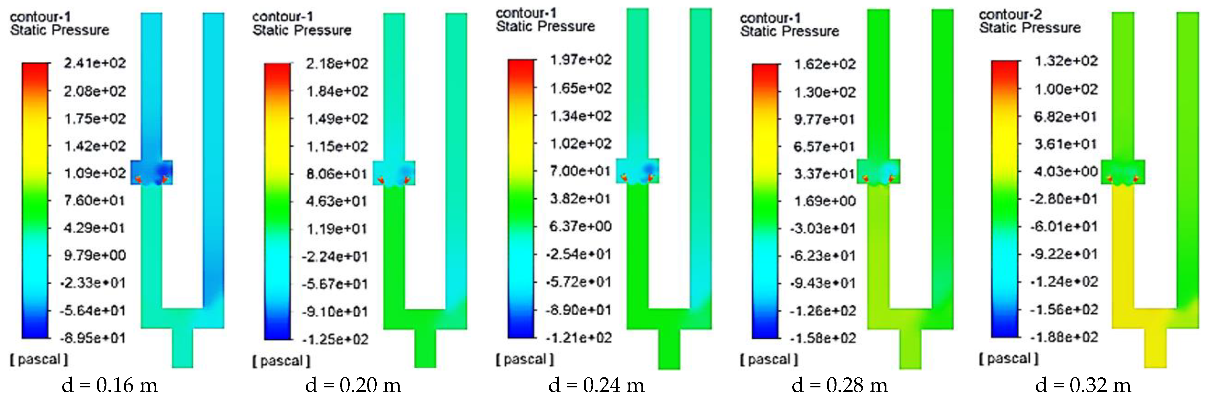
It can be seen in
Figure 20 that when the fan blade angle is 20° and the air curtain width is 0.16 m, the color upstream of the roadway is a very dark green and the pressure value is positive. As the width of the air curtain gradually increases to 0.32 m, the color upstream of the roadway gradually changes from dark green to light green and finally to yellow, but the color downstream also gradually warms, so the resulting partition pressure difference changes. In
Figure 21,
Figure 22 and
Figure 23, the colors of the upper and lower reaches of the roadway also show the same change pattern as in
Figure 20. Since the model adopts a three-dimensional large-section roadway, there will be local wind flow disorder. In order to reduce the error, the entire section of the roadway is taken 20 m upstream and downstream of the chamber, and the pressure average of the entire section is calculated using Fluent, and then the partition pressure difference generated by the air curtain is calculated.
From the calculation results of the above isolation pressure difference, it can be seen that the effective power made under different outlet widths and different fan full pressures is in the range of 1126.0~1425.9 W. The calculation result of the isolation pressure difference is shown in
Figure 24.
As shown in
Figure 24, we can see the relationship between the isolation pressure difference, the full pressure of the fan, and the outlet width of the air curtain. The different outlet widths and the full pressures of the fan determine the partition pressure difference of different sizes produced by the multi-machine parallel circulation air curtain.
When the fan blade angle is 20° and the air curtain outlet width is 0.08 m, the partition pressure difference generated by the air curtain is 38.3 Pa, and the partition effect is the worst. When the outlet width increases to 0.20 m, the isolation pressure difference increases to a certain extent, and the growth rate is large. As the outlet width continues to increase, so does the isolation pressure difference. When the outlet width is increased to 0.24 m, the partition pressure difference reaches the maximum, and the multi-machine parallel air curtain at this time has the strongest ability to resist the roadway air flow and the isolation effect is the best. As the outlet width continues to increase, the isolation pressure differential begins to decrease. By analyzing the folded lines at the angle of the fan blade of 25°, 30°, and 35° and different outlet widths, the same law as above can be obtained. This shows that under the full pressure of any fan, with the increase in the outlet width of the air curtain, the isolation pressure difference shows a trend of first increasing and then decreasing, and the ability to intercept the air flow of the roadway is first enhanced and then weakened. The partition effect reaches its best when it is 0.20~0.24 m.
3.4. The Influence of Air Curtain Outlet Width on Air Leakage Volume and Wind Choke Rate
In order to explore the influence of the outlet width of the air curtain and the full pressure of the fan on the air leakage volume and wind choke rate when the air flow of the roadway is isolated, a numerical simulation is made under the condition that the jet angle is unchanged by 30°, and different air curtain outlet width and different fan full pressure are selected as variables.
Due to the large number of models, only the velocity clouds and velocity vectors of the air curtain at different widths at a fan blade angle of 20° are listed here. The results are shown in
Figure 25.
The wind speed at the inlet of the roadway is 4 m/s, and when the air curtain is closed, the frictional wind resistance, local resistance, roadway break area, and other conditions of the two roadways are equal. Thus, the natural allocation of the components of the two roadways is 29.4 m
3/s, that is, the wind speed is equal to 2 m/s. From the velocity cloud figures in
Figure 25,
Figure 26,
Figure 27,
Figure 28 and
Figure 29, it can be seen that the wind speed distribution of the roadway has changed significantly under the action of air curtains with different outlet widths. Downstream of the roadway with the air curtain is dark blue and the speed is about 0.0~1.0 m/s, whereas the roadway without the air curtain is light blue and the speed is about 3.0~4.0 m/s. From the velocity vector diagram, it can be seen that the two jets of the air curtain form a closed air curtain in the middle of the roadway, and a circulating air flow is formed between the outlet and the inlet of the air curtain, which effectively intercepts part of the roadway air flow. However, it can also be seen that part of the air volume from upstream of the roadway is pumped away by the air curtain fan, and the remaining part flows downstream of the roadway, all with different degrees of air leakage.
In comparison, the downstream position of the chamber in
Figure 25,
Figure 28, and
Figure 29 is lighter in color, indicating that when the air curtain outlet width is 0.16 m, 0.28 m, and 0.32 m, the air leakage volume is larger and the ability to intercept the roadway air flow is weak. When the air curtain outlet width is 0.20 m and 0.24 m, the air leakage volume is small, and the ability to intercept the roadway air flow is strong. As can be seen from
Figure 27, when the air curtain outlet width is 0.24 m, the air flow through the air curtain is minimal.
A roadway section is taken 20 m downstream of the chamber, the average air volume of the entire section is calculated using FLUENT to be the air leakage volume, and then the wind choke rate under different air curtain outlet widths is calculated.
As shown in
Figure 30, it can be seen that there are two positive and negative values in the air leakage volume, and most of the positive values exist when the fan blade angle is 20°, 25°, and 30°. When the outlet width of the air curtain is 0.08~0.40 m, a negative value exists in the case that the full pressure of the fan is 35° and the outlet width is 0.24~0.32 m. When the full pressure of the fan is 20°, the air leakage is positive at any outlet width. This shows that the outlet width of the multi-machine parallel air curtain at this time is within 0.08~0.40 m, which has a certain effect on intercepting the air flow of the roadway, and with the increase in the outlet width, the air leakage volume first decreases and then increases.
In the process of increasing the width of the air curtain outlet, the resistance in the air curtain formed by the two jets of the air curtain to the lateral pressure of the roadway wind flow gradually increases, and the effect of intercepting the roadway wind flow becomes better and better. When the outlet width is increased to 0.24 m, the interception effect is best. When the outlet width continues to increase, the air leakage volume begins to increase and the interception effect begins to weaken. This shows that when the outlet width is 0.24 m, the energy loss in the multi-machine parallel air curtain is the smallest, and the interception effect is the strongest. The same variation law can be obtained by analyzing the broken lines with fan blade angles of 25° and 30°. When the angle of the fan blade is 35° and the outlet width is 0.20 m, the air leakage volume is positive, and the air leakage decreases with the increase in the outlet width, indicating that the effect of intercepting the air flow in the roadway increases, which is in line with the law of the air curtain when it exerts the effect of intercepting the air flow. When the outlet width is 0.24~0.32 m, the air leakage volume is negative, and it decreases first and then increases with the increase in outlet width, indicating that this node is the critical point of the isolation and drainage air flow.
Figure 31 shows the relationship between the multi-machine parallel circulation air curtain, outlet width, and wind choke rate. The efficiency of the air curtain intercepting roadway air flow can be intuitively seen. When the choke rate exceeds 100%, it indicates that the air curtain has changed from a state of intercepting wind flow to an induced air flow. When the angle of the fan blade is 20°, 0.08~0.40 m, the corresponding wind choke rate is 67.0~74.1%. The wind choke rate is lowest when the outlet width is 0.08 m, and the maximum value is reached at a width of 0.24 m. As the outlet width continues to increase, the choke rate begins to decrease. At the fan blade angles of 25° and 30°, the wind choke rate is less than 100%. This shows that under the conditions of full pressure and outlet width, the multi-machine parallel air curtain can effectively intercept the wind flow, and the interception effect first increases and then weakens with the increase in outlet width, which is the same as when the blade angle is 20°.
When the fan blade angle is 35°, it can be seen that the choke rate increases with the increase in the outlet width. When the outlet width is increased to 0.24 m, the wind choke rate reaches 101.7%, and the wind flow from intercepting roadway to draining air flow begins to change.
From
Figure 31, it can be seen that when the full pressure of the fan is small, the ability to intercept the wind flow can be improved by increasing the width of the air curtain outlet. Although increasing the full pressure of the fan can also improve the air flow capacity of the partition roadway of the multi-machine parallel air curtain, it will increase additional power consumption and cause unnecessary waste. According to the relationship between the full pressure of the fan, the width of the air curtain outlet, and the wind choke rate, by combining the actual needs, the design of the air curtain outlet width can provide certain guidance for the practical application of multi-machine parallel air curtains, reduce energy consumption and enhance economic value.


