Article

Optimization and Application of Water Injection Process in Gas-Bearing Coal Seam

1
College of Safety and Environmental Engineering, Shandong University of Science and Technology, Qingdao 266590, China
2
Luling Coal Mine, Huaibei Mining Co., Ltd., Suzhou 234113, China
*
Author to whom correspondence should be addressed.
Processes 2023, 11(10), 3003; https://doi.org/10.3390/pr11103003
Submission received: 19 September 2023 / Revised: 12 October 2023 / Accepted: 16 October 2023 / Published: 19 October 2023

Abstract

:
Coal seam pre-drainage technology is widely used to prevent and control gas in China’s high-gas coal seams, and upward drilling is a safe and reliable technology. Using the Luling Coal Mine as the study location, according to the actual situation of the site, a layer-through drilling process was proposed. Relying on a cross-layer extraction borehole, coal seam water injection efficiency extraction and high-efficiency water injection dust prevention can be performed in the later stage of borehole extraction, enabling one-hole multi-purpose and “gas-powder” integrated prevention and control. In order to study the “stress-seepage” coupling characteristics of the coal around the borehole, a numerical simulation of the coal seam water injection process was conducted. Based on the simulation results, a field test of water injection in coal seam upward drilling was performed. The field monitoring data show that the water injection and water content of the coal seam were increased by about 3.07 m3 and 0.69%, respectively, compared with the traditional water injection process. The water injection effect is remarkable, which is of great significance to ensure the safe and efficient production of the mine.

1. Introduction

As the most abundant energy source in the world, coal has become the basis for promoting rapid economic development. It is still the main energy source that has been used to support the social and economic development of our country for a long time [1,2]. However, in the process of coal mining, spontaneous coal combustion, gas explosions, and coal mine dust-induced accidents often occur [3,4,5,6,7,8,9,10,11,12,13], which seriously affect the underground green environment, bring serious and fatal damage to the miners, and cause huge economic losses. In China, the most widely used technology to curb disasters from the source is coal seam water injection [14,15,16], which can effectively prevent the occurrence of coal mine accidents.
Coal seam water injection refers to the injection of high-pressure water into the coal body through drilling before coal seam mining, so that the water flow diffuses along the cracks and bedding of the coal body, thereby increasing the water content of the coal seam [17], infiltrating the coal body in advance [18,19], and reducing dust production [20], which can effectively improve the production environment of the working face and achieve the purpose of controlling coal and gas outbursts, coal dust, and other coal mine disasters. At present, coal seam water injection has been widely used, and water injection methods tend to be diversified [21,22]. Many scholars have carried out extensive research on water injection technology [23,24,25,26,27,28,29,30,31,32,33,34,35,36]. However, the traditional coal seam water injection process has problems, such as high ground stress, low porosity, and poor permeability [37,38,39], which fails to meet the actual needs of the site, and seriously restricts and affects the disaster prevention and dust reduction effects of coal seam water injection.

Water Injection Technology

To sum up, how to realize the synchronous control of “gas-dust” and improve the efficiency of existing engineering disaster prevention technology is an urgent problem to be solved in coal mine disaster prevention and control. In this paper, the III 1022 working face of the Luling Coal Mine was taken as the research object, and the simulation software Flac3D6.0 was used to simulate the seepage field of coal seam water injection. According to the simulation results combined with the actual situation of the coal mine site, the field coal seam water injection process was improved. In view of the singleness of gas extraction boreholes and the decrease in gas extraction efficiency in the later stage of pre-drainage, “one hole multi-purpose” layer-through high-efficiency sealing technology was developed. The study of the stress–seepage coupling law around the coal body of water injection boreholes provides a basis for the optimization of the coal seam water injection process, and has important guiding significance for the realization of coal mine production safety.

2. The “ Stress–Seepage ” Coupling Characteristics of Coal around Boreholes

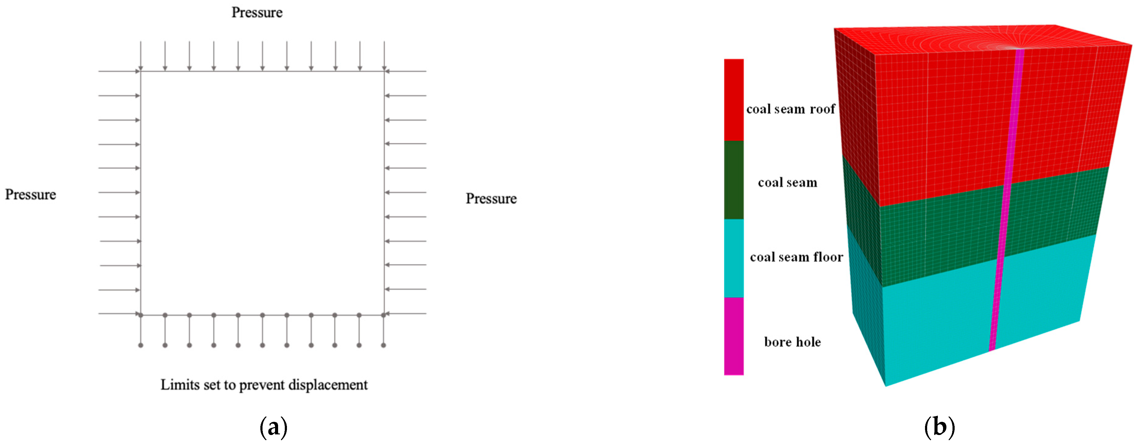
2.1. Stress Distribution Characteristics of Coal around Boreholes

2.1.1. Stress Distribution Characteristics of Coal around the Borehole Prior to Water Injection

During the drilling process, the redistribution of stress in the encompassing coal body gives rise to distinct zones, namely pressure relief zones, stress concentration zones, and original rock stress zones. The permeability of coal seams can vary across different regions, making it challenging to directly ascertain the stress distribution surrounding a borehole. The Lagrangian algorithm used by Flac3D does not form a stiffness matrix in the calculation, and does not need to iterate to satisfy the elastoplastic constitutive relationship, but only needs to calculate the stress through strain. Therefore, it is more suitable for the excavation calculation of a nonlinear rock mass with a large volume, divided units, and more nodes [40]. It is widely used in geotechnical engineering, mining engineering, and other fields [41,42]. Consequently, in this study, we employed Flac3D6.0 simulation software to construct a numerical model to study water injection engineering through boreholes. The three-dimensional fast Lagrangian finite difference program was used to analyze the mechanical characteristics of the plastic failure of a coal-and-rock mass when it reached the strength limit.
This study took the III1022 working face of the Luling Coal Mine in Suzhou City, Anhui Province, as the simulation background. The III 1022 fully mechanized mining face plane layout diagram is shown in Figure 1. The working face is the first mining face of 10 coal seams in the III2 mining area. The model can be mined to 1350 m, the inclined length is 170 m, and the mining height is 2.4 m. The maximum original gas pressure of the working face is 2.6 MPa (−711.6 m), and the maximum original gas content is 13.79 m3/t (−711.6 m), making it an outburst danger area. Located in the central mining area of the mine, the geological structure is relatively simple compared to the east and west. The overall performance of the coal seam is a monocline structure with a northwest trend and a tendency to the northeast, and the coal-measure strata have a stable occurrence. The local area is affected by the fault structure, and the stratum has small ups and downs. The dip angle of the stratum in the working face is 15~22°.
The numerical model is shown in Figure 2 and is based on the actual situation at the site. The length × width × height of the model is 10 m × 10 m × 8 m, and the buried depth of the model is 710 m. Therefore, a stress of 15.6 MPa needs to be applied [43]. The model is divided into 96,000 units. The model parameters are listed in Table 1.
In this study, the Mohr–Coulomb elastoplastic constitutive model was used as a basis, and several adjustments were made to the model to better meet the research requirements for coal seam water injection. In the upper part of the model, considering the existence of the free surface, an overburden pressure load of 15.6 MPa was applied to simulate the in situ stress of the overlying strata, and the direction of the load was vertical downward. In addition, we also considered factors such as the influence range of the goaf, and we set conditions to limit the displacement around and at the bottom of the model to simulate the actual situation more realistically. After the initial operation of the model, we analyzed the stress distribution of the coal around the borehole and obtained the corresponding cloud map, as shown in Figure 3.

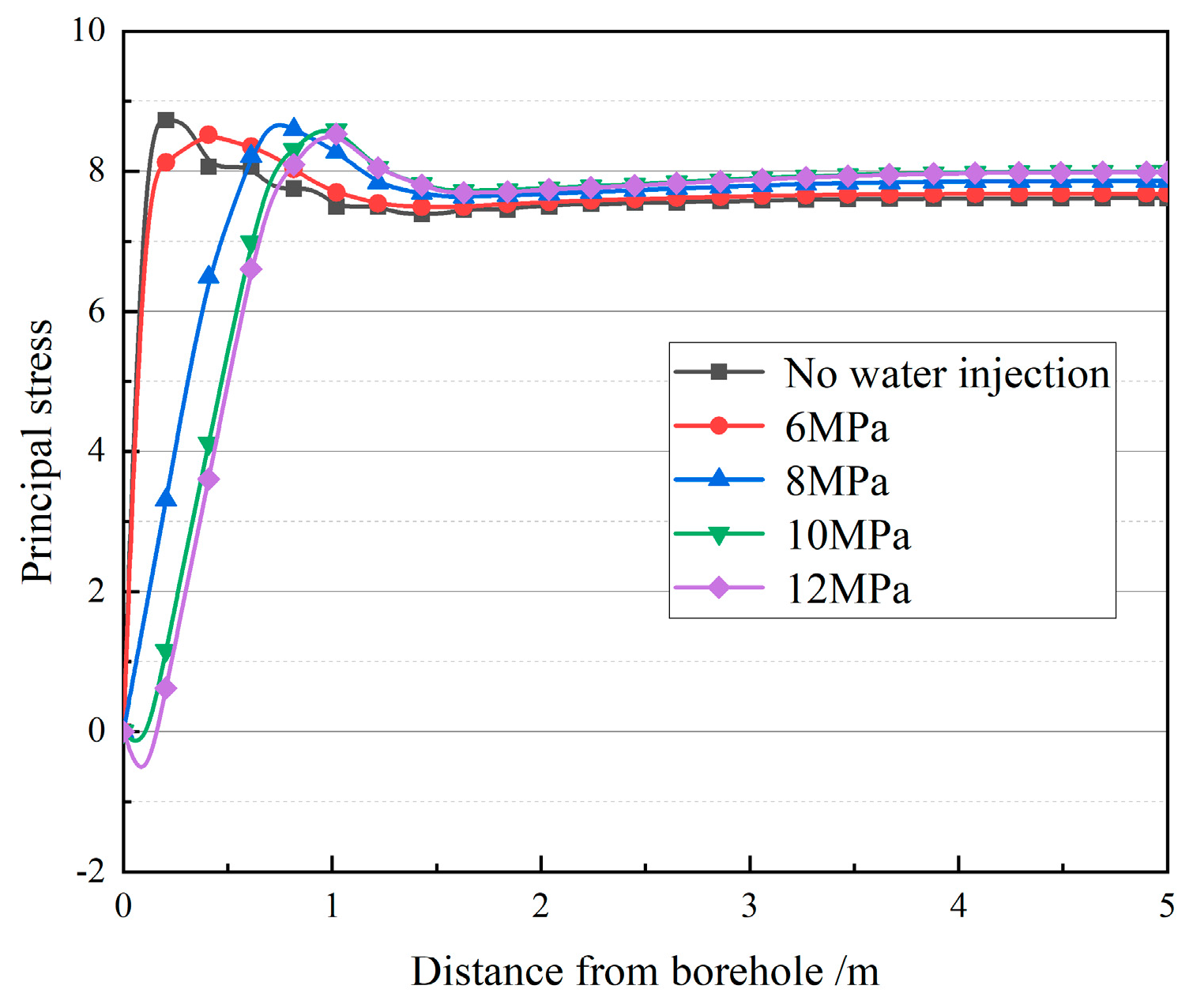
2.1.2. Stress Distribution Characteristics of the Coal around the Borehole after Water Injection

The FISH language mechanics calculation compiler in Flac3D numerical simulation software was used to construct a plug-in program that could independently perform seepage calculation. Under different water injection pressure conditions, after the stress of the coal body around the borehole prior to water injection formed a secondary balance, the default seepage operation constitutive model of the numerical simulation software was changed such that the seepage operation program conformed to the change law of the coal sample permeability and improved the accuracy of the test results.
In practical engineering applications, the water injection pressure should be lower than the formation pressure and higher than the coal seam gas pressure. This is generally calculated according to the following formula [43]:
( 1.2 ~ 1.5 )   P G P Z 0.75 P R
where P G is the gas pressure in the coal seam [MPa]; P Z is the water injection pressure [Mpa]; and P R is the overburden pressure, P R = 0.01   ρ H , where ρ is the average density of the overlying strata, and H is the average thickness of the overlying strata [m].
According to Equation (1), the theoretical water injection pressure is between 3 MPa and 12 MPa. Therefore, based on the actual occurrence of the coal seam and the numerical simulation model, the vertical downward overburden pressure was set to 15.6 MPa, and the water injection pressure was set to 6 MPa, 8 MPa, 10 MPa, and 12 MPa by the seepage operation program. Multiple water injection simulation tests were performed, and the specific water injection test parameters are shown in Table 2.
Using different injection pressures (6 MPa, 8 MPa, 10 MPa, and 12 MPa) to inject the water, the radial pore pressure cloud map of the borehole can be observed to obtain the distribution law of the principal stress around the borehole under different injection pressures.
As shown in Figure 4, taking the water injection pressure of 6 MPa as an example, when the water injection pressure is constant, the hydraulic influence area is quasi-circular. With the increase in water injection time, the hydraulic influence range gradually expands, and the stress concentration area is affected by the water injection, which gradually moves away from the borehole along the radial direction of the borehole. When the water injection time is fixed, with increasing water injection pressure, the diffusion range of the water along the radial direction of the borehole increases, and the diffusion speed also increases. At the same position as the distance from the borehole, the pore pressure increases. The diffusion rate of the water increases nearly uniformly with the increasing water injection pressure.
The stress evolution law of a coal seam under different water injection pressures can be obtained from Figure 5. When the water injection pressure is relatively small (6 MPa), there is no obvious movement of the peak point of the principal stress after water injection, and the peak stress is reduced to 8.5 MPa. When the water injection pressure is 8 MPa, the principal stress of the coal around the borehole is further unloaded, and the principal stress in a range of 0.26 m from the borehole is completely relieved. The peak point of the principal stress moves 0.31 m along the radial depth of the borehole, the pressure relief range is expanded to 0.71 m, and the peak stress increases to 8.7 MPa. When the water injection pressure increases to 10 MPa, the peak point of the principal stress moves 0.31 m along the radial depth of the borehole, the pressure relief range is expanded to 1.02 m, and the peak value of the principal stress is decreased to 8.6 MPa. When the water injection pressure further increases to 12 MPa, the movement effect of the stress concentration zone is not obvious, and the peak point of the principal stress does not change significantly, remaining between 10 MPa and 12 MPa.
As shown in Figure 5, the stress exhibits a decreasing trend, followed by an increase, and then stabilizes with increasing distance from the borehole. This phenomenon can be attributed to the impact of the water injection in the surrounding coal seam. Specifically, water injection leads to an increase in the pore water pressure, which partially offsets the overburden pressure, resulting in a decrease in the principal stress around the borehole. However, as the water injection pressure continues to rise, the stress around the borehole also increases. This leads to an expansion of the pressure relief area, consequently enhancing the effectiveness of the pressure relief. Furthermore, with the progressive increase in the water injection pressure, the range of the stress concentration area shifts towards deeper regions of the coal seam.

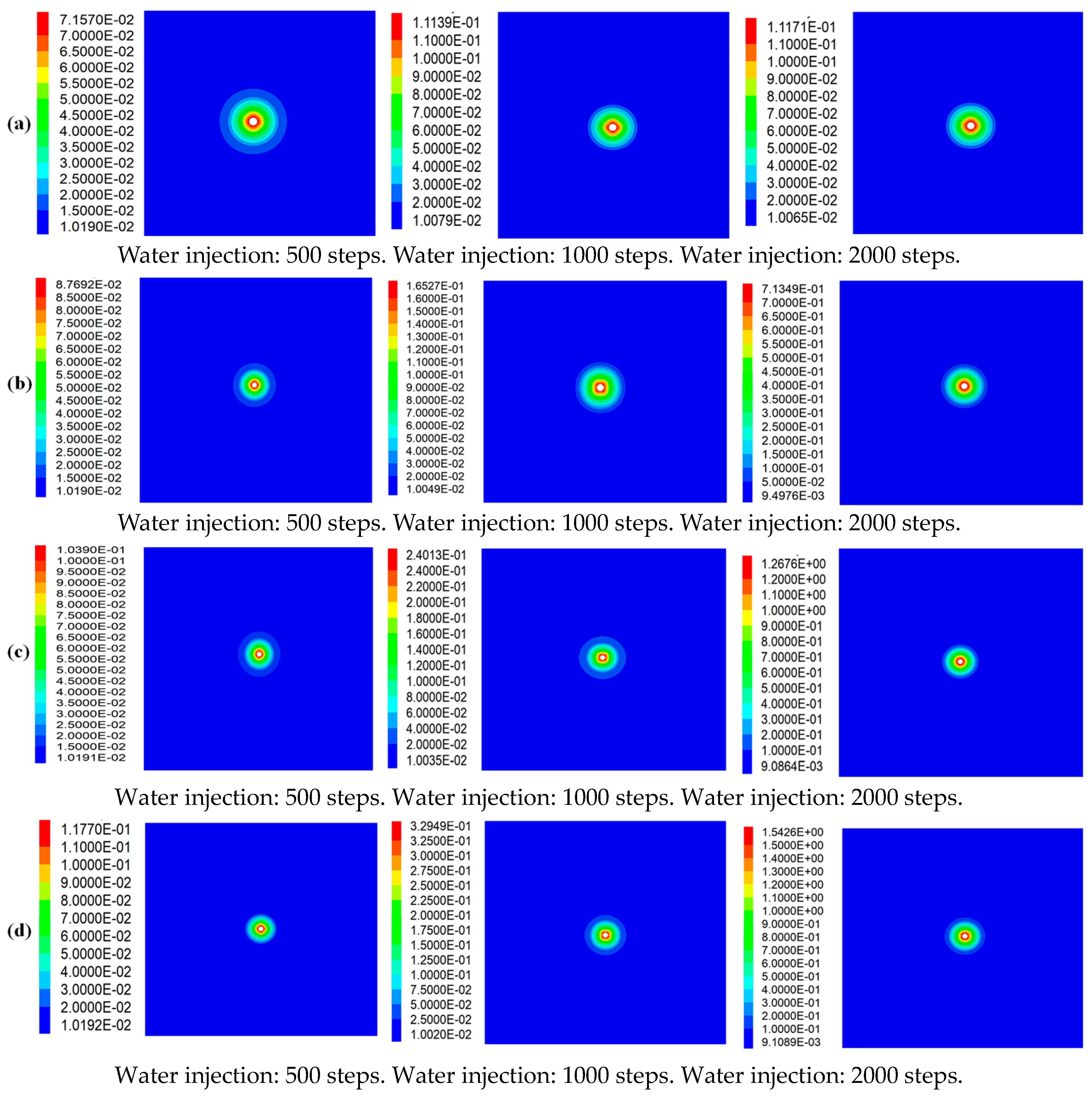
2.2. Seepage Characteristics of Coal around Boreholes

Under an overburden pressure of 15.6 MPa, the model was injected with water at 6 MPa, 8 MPa, 10 MPa, and 12 MPa. The change law of the permeability of the model was recorded at the same time.
Figure 6 shows that, with increasing water injection pressure, the hydraulic influence range expands, and the permeability experiences a proportional increase as a result of the impact of the water injection. Conversely, when the water injection pressure remains constant, an augmentation in the water injection time leads to a decrease in the initiation difficulty of hydraulic fracturing, consequently expanding the range of the influence of the permeability.
Figure 7 shows the permeability distribution of the coal around the borehole. When the water injection time is fixed, the water injection pressure gradually decreases from its highest point at the borehole wall to a point away from the borehole until it reaches the original permeability. However, the increase in the coal permeability differs under different water injection pressures. The maximum permeabilities of coal corresponding to water injection pressures of 6 MPa, 8 MPa, 10 MPa, and 12 MPa are 0.04, 0.11, 0.71, 1.26, and 1.48, respectively, which are 1.75%, 16.75%, 30.5%, and 36% higher than the original permeability of the coal. In the effective wetting range of the coal body, a greater water injection pressure at the same position corresponds to a greater permeability of the coal body. Therefore, the effect of a low water injection pressure on the fracturing and permeability enhancement of a coal body is not obvious, and the permeability does not change significantly. Under the action of a high water injection pressure, the pores and fissures in the coal body are interconnected, which increases the migration channels of the water in the coal body, and the permeability changes significantly. Therefore, increasing the water injection pressure properly can increase the permeability of the coal and improve the effect of water injection.

3. Optimization of the Water Injection Process in a Gas-Bearing Coal Seam

Based on the above numerical water injection simulations, the existing water injection process in the coal mine can be optimized.

3.1. Sealing Process Optimization

Table 3 indicates that the working face of the field test has a long tendency distance and that the coal seam has a large dip angle. Because of the self-weight of the sealing material, the front-end plug of the borehole cannot be laid at a predetermined depth, and the surrounding rock cracks cannot be tightly sealed; this seriously affects the extraction effect of the coal seam gas.
According to the actual on-site situation, this study proposed a deep hole sealing process for cross-layer water injection drilling, as shown in Figure 8. First, the high-pressure water injection pipe, the hole packer, and the slurry return pipe are fastened together using steel wire, and the traction steel wire, with a length greater than the drilling depth, is tied at the front end of the hole packer; the traction steel wire is then passed through the push pipe. Next, with the help of the push pipe, the hole packer is pushed to a position 0.5 m beyond the coal point. The push pipe is then extracted to emplace the high-pressure water injection pipe, hole packer, slurry return pipe, and steel wire in the borehole. Finally, after the borehole is sealed, the grouting pump injects slurry into the gap between the two sealed bags. When slurry outflow occurs in the slurry return pipe, the ball valve of the slurry return pipe is closed. The grouting continues until the pressure reaches 1 MPa; then, it is stopped.

3.2. Coal Seam Water Injection Process Optimization

3.2.1. Adding a Surfactant

When water is injected into the coal seam, the coal body is in contact with the liquid injection and is wetted by it. This step plays a significant role in the infiltration process. However, it is difficult to achieve ideal results by using ordinary mine water in the Luling Coal Mine when wetting the coal body. By adding surfactants to reduce the polarity of water and increase the uniformity of the water in the coal body structure, the wetting effect of the coal seam can be significantly improved.

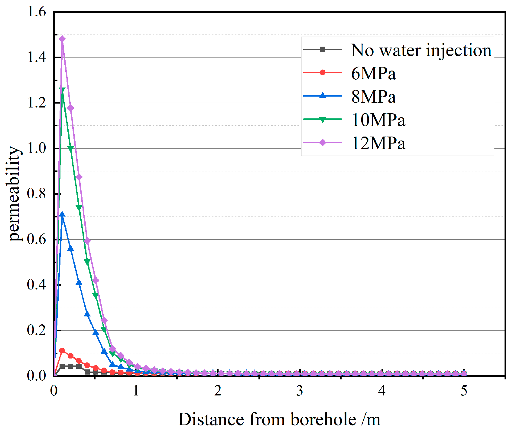
3.2.2. Water Injection Pressure Optimization

It can be seen from the second section that the effect of coal seam water injection is affected by the water injection pressure. Because of the complex geological conditions of coal seams, it is generally difficult for fluids to flow effectively under natural conditions; accordingly, a certain pressure should be applied during water injection operations.

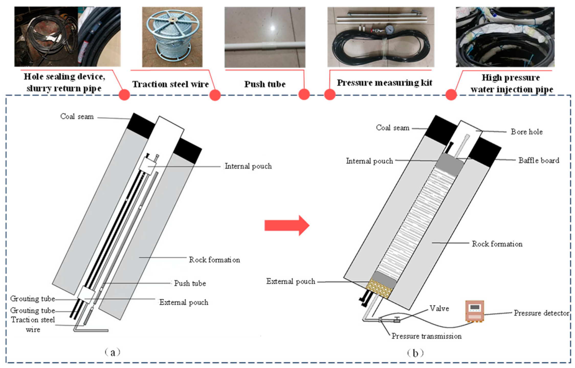
3.2.3. Optimization of the Water Injection Equipment

According to the evolution law of the stress–seepage field and the field practice of coal seam water injection, real-time acquisition-segment precision control technology for the physical parameters of the water injection power and liquid injection, with a programmable information control system as the core, was developed. Based on existing monitoring sensing technology and automatic control theory, the core of the field equipment is the logic controller, and the water injection parameters and liquid injection properties are its control objects. At the same time, it is equipped with a data monitoring substation, a real-time transmission module, and an intelligent transmission unit. The field equipment can complete intelligent data acquisition, transmission, and processing and real-time system response feedback control and realize the dynamic monitoring and control of the water injection dynamic parameters. The process principle of the field equipment is shown in Figure 9.

4. Field Test and Implementation Effect

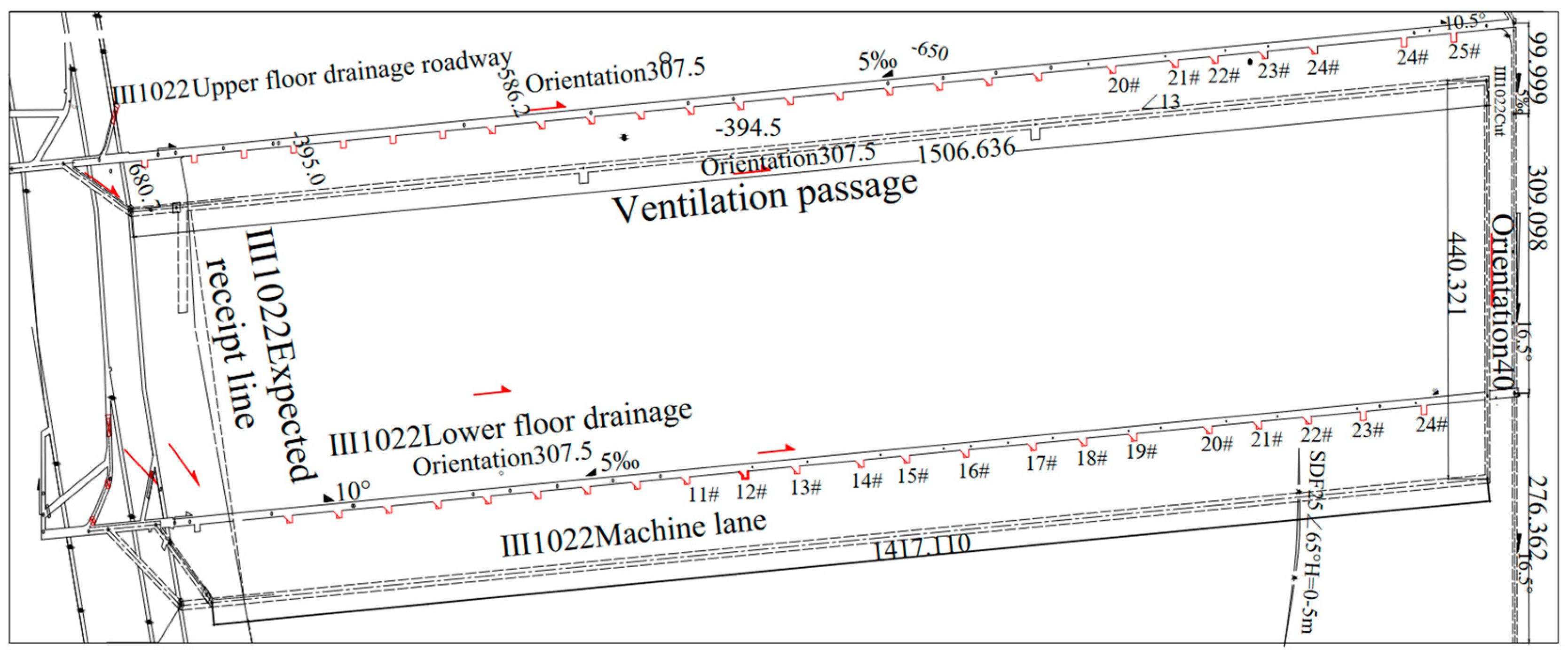
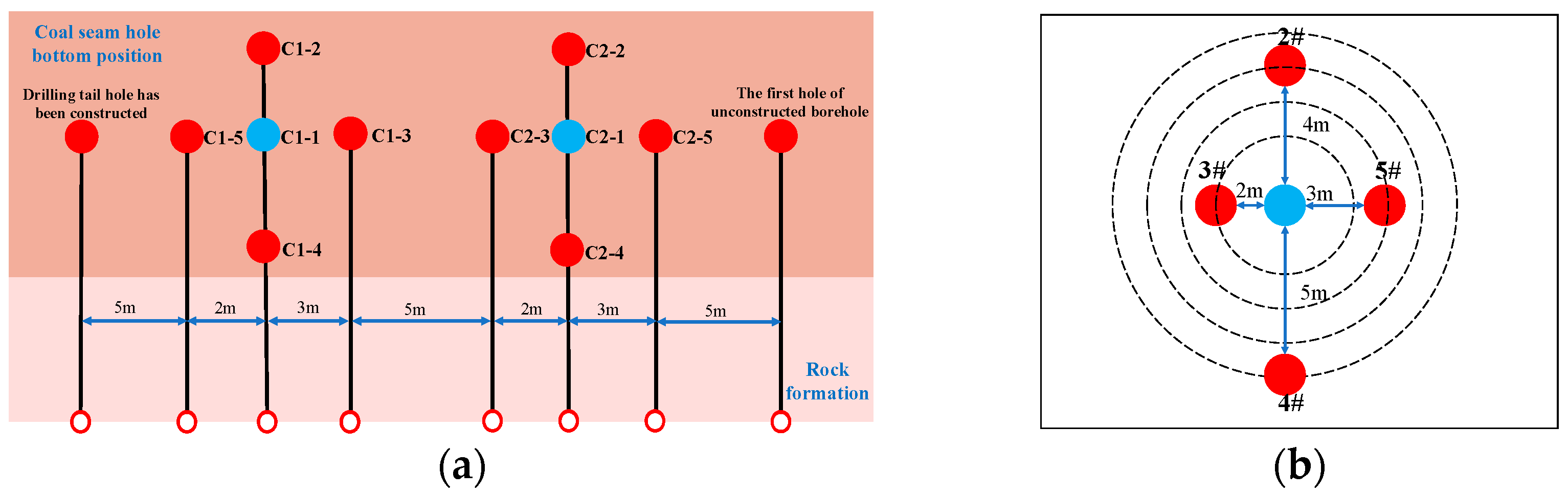
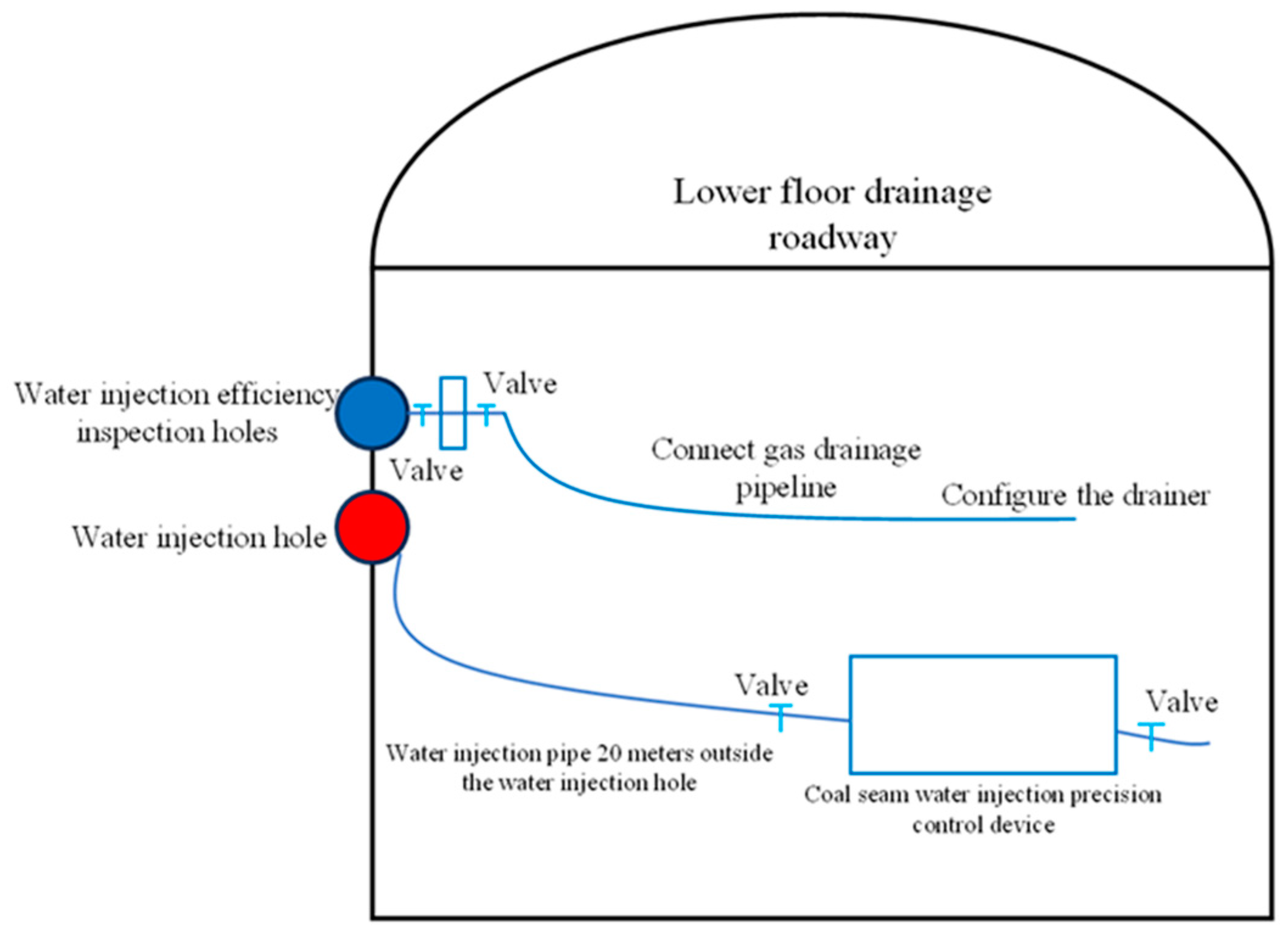
4.1. Field Test Schematic Design

To investigate the multi-purpose effect of “ cross-layer drilling”, two upward cross-layer drilling groups were constructed in the lower floor drainage roadway of the III1022 working face. The principle of annular drilling was adopted, as shown in Figure 10, and the C1 and C2 group drillings consisted of five drillings each. In each, one drilling was for water injection, and the remaining four drillings were water injection efficiency inspection holes.

Water Injection Test Steps

(1) The traditional water injection process test was carried out on the group C1 boreholes.
According to the schematic diagram of the pipeline connection between the water injection hole and the efficiency inspection hole in Figure 11, the rapid connector is used to connect the precise measurement and control device for the coal seam water injection with the existing water injection pipeline and access the C1-1 water injection hole after sealing. After sealing, the C1-2, C1-3, C1-4, and C1-5 efficiency inspection hole ends are equipped with a gas–water pressure monitoring device and a drainage pipe with a valve that can display and save data. After the pipeline connection is completed, the water injection pump is used to inject clean water. By observing the change in the pressure gauge at the end of the efficiency inspection hole, the change in gas–water pressure in each efficiency inspection hole is judged. When the pressure of the water injection pump is reduced to about 30% of the peak pressure, and the change in the pressure gauge at the end of the efficiency inspection hole tends to be stable, the water injection is stopped.
(2) A step-by-step water injection test was carried out on the C2 group boreholes.
The rapid connector is used to connect the precise measurement and control device for the coal seam water injection with the existing water injection pipeline and access the C2-1 water injection borehole after sealing. As shown in Figure 12, the gas–water pressure monitoring device and the drainage pipe with a valve that can be digitally displayed and can save the data are installed at the end of the C2-2, C2-3, C2-4, and C2-5 efficiency inspection holes after sealing. After the completion of the pipeline connection, the key nodes of water injection power and fluid physical parameter regulation are obtained according to the water injection pressure–flow variation law obtained in Experiment 1. The required dynamic parameters and fluid physical parameters are calculated according to the theoretical model, and the step-by-step water injection test is continued for the C2 group of boreholes. For stepwise water injection, the following three steps need to completed:
(1)
Before the start of water injection, thickener is added to the matching water tank to improve the viscosity of the fluid. According to the ratio, clean water is injected into the matching water tank and stirred evenly to complete the preparation of the thickener. Then, the water injection pump is started, and the flow regulation valve is used to continuously increase the water injection flow rate, so as to open multiple water injection main cracks and promote the expansion of secondary cracks.
(2)
When the water injection flow is increasing and the water injection pressure begins to decrease, it indicates that the water injection initiation process is completed. The fluid is replaced with a prepared surfactant, and the water injection flow is continuously increased through the water injection pump to reduce the fluid viscosity, increase the fluidity, and expand the influence range of the water injection.
(3)
When the water injection flow rate increases continuously and the water injection pressure increases again, it indicates that the water is wetted by seepage under the dual action of capillary force and surface tension. The fluid is replaced with a prepared high-concentration surfactant, and the water injection flow is continuously increased through the water injection pump to continuously reduce the surface tension between the liquid–solid two-phase contact surface and promote the further migration of water.
When the pressure of the water injection pump is reduced to about 30% of the peak pressure, and the change in the pressure gauge at the end of the efficiency inspection hole tends to be stable, the water injection is stopped.

4.2. Water Injection Efficiency Analysis

4.2.1. Investigation of the Sealing Effect Prior to Water Injection

The above-mentioned sealing process was used to seal the hole and test the sealing effect. After 48 h of gas pressure balance, the gas pressure in the efficiency inspection hole and the water injection hole was monitored using a digital monitor, and 30 min of data was intercepted. The resulting change rule is shown in Figure 13.
The variation law of the gas pressure in the borehole shown in Figure 13 indicates that within the monitored time range, the pressure changes in each borehole fluctuated within a certain range and did not fully reach the equilibrium state. The fluctuations in the C1-3 and C1-4 boreholes of the efficiency inspection hole were small, and the change in the gas pressure was relatively stable. The fluctuations in the C1-1 and C1-5 boreholes of the water injection hole were relatively large, and the fluctuation in the C1-2 borehole of the efficiency inspection hole was the largest. The stability of the gas pressure was poor, which was due to the analysis process. The variation law of the average gas pressure in the borehole was as follows: from C1-1 to C1-2, the average gas pressure decreased; from C1-2 to C1-4, the average gas pressure gradually increased; and from C1-4 to C1-5, the average gas pressure slowly decreased. The diagram also indicates that the air tightness of each borehole and the connecting pipeline outside the borehole were good, and that a good pressure holding effect was successfully realized.

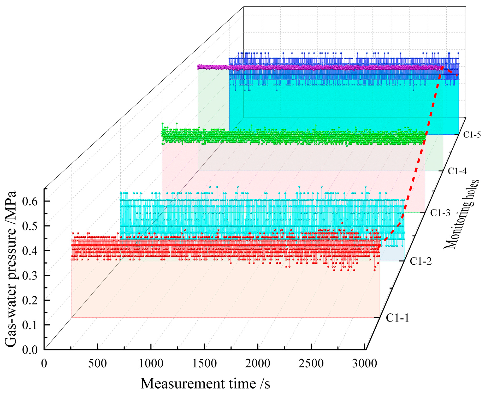
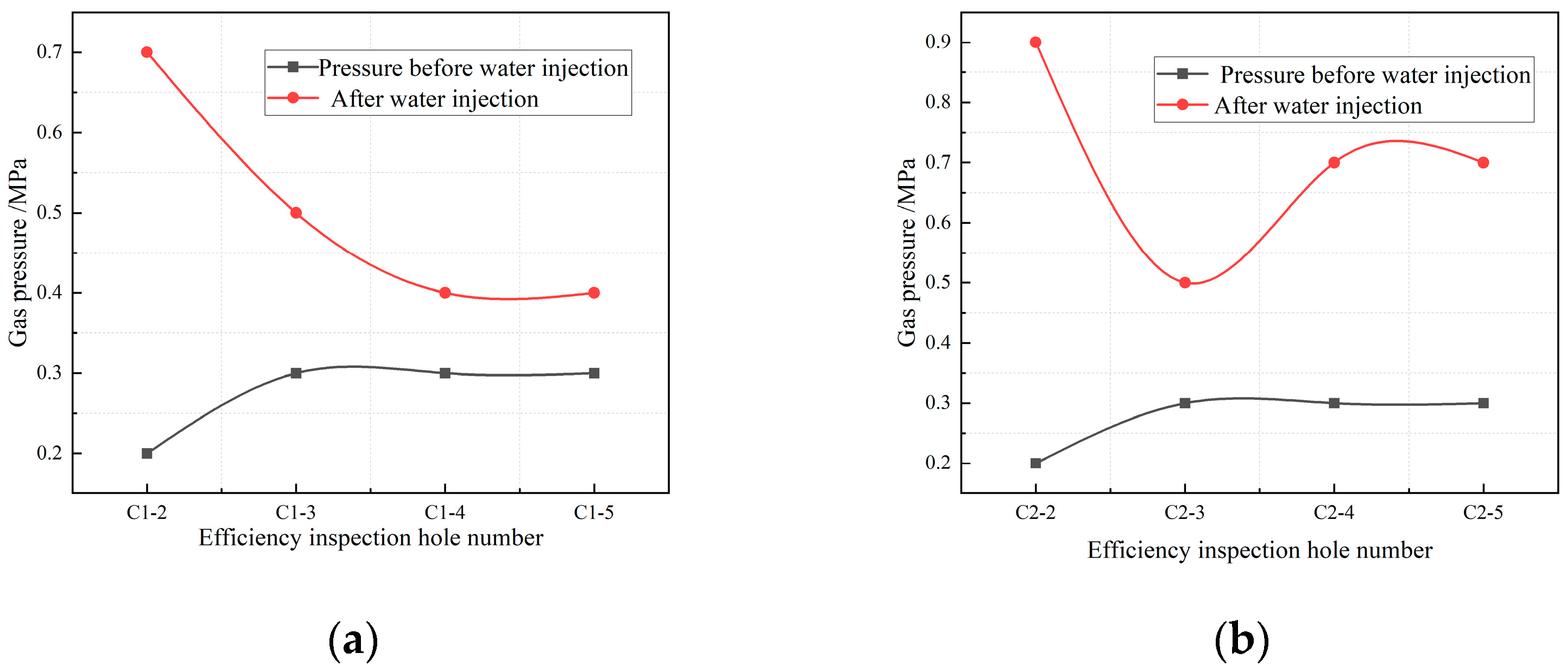
4.2.2. Investigation of the Water Injection Effect on the On-Site Coal Seam

The two groups of boreholes were subjected to water injection; group C1 was subjected to a traditional water injection process test, and group C2 was subjected to a step-by-step water injection test. A comparison of the change in the two-hour average pressure of the efficiency test holes before and after water injection into the two groups of boreholes is shown in Figure 14. The gas–water pressure in the two groups of test holes showed a significant increasing trend with the completion of the water injection; the pressure increase of group C2 was greater than that of group C1. The main reason for this is that the depth and breadth of the seepage channel were further effectively extended when the group C2 boreholes were subjected to the step-by-step water injection, thereby increasing the gas–water pressure and verifying the effectiveness of step-by-step water injection for strong permeability and permeability enhancement. Moreover, with the same group of boreholes, the pressure increase in the calibration hole near the bottom of the water injection borehole was always the largest. This is because only the gas pressure is included in the initial pressure test process. With progressive water injection, water and gas can flow quickly out through the calibration hole below. According to the above field test results, it is clear that the step-by-step water injection technology achieved good results.
It can be seen from Table 4, in terms of single-hole water injection, the water injection volume of group C1 was approximately 2.67 m3, while the water injection volume of group C2 increased to approximately 5.60 m3. In terms of the water content of the coal around the borehole after the water injection, the average water content of the boreholes in group C1 was approximately 3.73%, while the average water content of the boreholes in group C2 increased to approximately 4.42%. The water content of the boreholes in group C2 was greater than that of group C1, that is, the step-by-step water injection method significantly improved the water content in the coal body, thereby achieving a better dust reduction effect and increasing the gas extraction efficiency.

5. Conclusions and Prospects

5.1. Conclusions

Using numerical simulations, the stress–permeability evolution law in the process of coal seam water injection was studied. Water injection has a significant effect on the stress distribution of the coal around a borehole, and with increasing water injection pressure, the cracks in the coal around a borehole further expand, and the influence range of the borehole water injection increases. On this basis, water injection technology for upward cross-layer drilling in a gas-bearing coal seam was proposed, and the sealing technology of an upward cross-layer water injection depth hole was developed, solving problems associated with a long sealing distance, rough hole walls, and a large borehole dip angle. Field tests were performed on 10 coal seams in the Luling Coal Mine. Compared with the traditional water injection process, the water injection volume and water content of the coal seam increased by approximately 3.07 m3 and 0.69%, respectively, effectively displacing the gas in the coal seam, achieving a better dust reduction effect, and improving the comprehensive disaster prevention effect of water injection.

5.2. Prospects

(1)
As the coal seam is a typical grey system, it is impossible to directly obtain the actual change in stress in the process of water injection. With laboratory experiments and field tests, it is also difficult to completely reproduce the evolution characteristics of stress in the process of water injection that occur under the real mechanical environment. In this paper, the change in the coal stress field around the water injection borehole was obtained by numerical simulation. In the future, the real-time monitoring function of coal stress and strain in the seepage process can be realized by further improving the experimental system and using experimental research methods.
(2)
In the process of carrying out the engineering practice of step-by-step control technology for coal seam water injection, although the parameters, such as water injection pressure-flow rate, in this paper realized the real-time monitoring of the whole process of water injection, the control of key parameters and the core control equipment still need further study, and on this basis, the automatic and accurate solution of a mathematical analytical model was realized, and the automatic and intelligent coal seam water injection was completed, so as to further improve the effect of coal seam water injection disaster reduction.

Author Contributions

Conceptualization, Z.L.; data curation, N.G. and Q.G.; funding acquisition, Z.L.; investigation, N.G.; methodology, X.L. and P.H.; supervision, Z.L.; writing—original draft, X.L.; writing—review and editing, X.L. All authors have read and agreed to the published version of the manuscript.

Funding

The authors received funding from the National Natural Science Foundation of China (52274213, 52074173, 51934004), Natural Science Foundation of Shandong Province (ZR2022YQ52), and Taishan Scholars Project Special Funding.

Institutional Review Board Statement

Not applicable.

Informed Consent Statement

Not applicable.

Data Availability Statement

Not applicable.

Acknowledgments

The authors would like to acknowledge the support of the National Natural Science Foundation of China (52274213, 52074173, 51934004), Natural Science Foundation of Shandong Province (ZR2022YQ52, ZR2023QE132), and Taishan Scholars Project Special Funding.

Conflicts of Interest

The authors declare no conflict of interest.

References

  1. Liu, Z.; Hu, P.; Yang, H.; Yang, W.; Gu, Q. Coupling mechanism of coal body stress-seepage around a water injection borehole. Sustainability 2022, 14, 9599. [Google Scholar] [CrossRef]
  2. Liu, Z.; Jiao, L.; Yang, H.; Zhu, M.; Zhang, M.; Dong, B. Study on the microstructural characteristics of coal and the mechanism of wettability of surfactant solutions at different pH levels. Fuel 2023, 353, 129268. [Google Scholar] [CrossRef]
  3. Zeng, M.; Shi, S.; Lu, Y.; Li, H.; Wu, K. Research on current situation of coal and gas symbiosis disaster. China Energy Environ. Prot. 2020, 42, 6–9. [Google Scholar]
  4. Xu, T.; Wang, X. Statistics and Law Analysis of Gas Explosion Accidents in Low Gas Coal Mines in China in Recent Ten Years. Min. Saf. Environ. Prot. 2021, 48, 126–130. [Google Scholar]
  5. Deng, Q.; Wang, Y.; Liu, M. Statistical analysis and enlightenment of coal mine accidents in China from 2001 to 2013 years. Coal Technol. 2014, 33, 73–75. [Google Scholar]
  6. Li, B. Study on the basic characteristics and occurrence law of coal and gas outburst accident in China from 2001 to 2012. J. Saf. Environ. 2013, 13, 274–278. [Google Scholar]
  7. Weissman, D.N. Progressive massive fibrosis: An overview of the recent literature. Pharmacol. Ther. 2022, 240, 108232. [Google Scholar] [CrossRef]
  8. Ferguson, J.M.; Costello, S.; Elser, H.; Neophytou, A.M.; Picciotto, S.; Silverman, D.T.; Eisen, E.A. Chronic obstructive pulmonary disease mortality: The diesel exhaust in miners study (DEMS). Environ. Res. 2019, 180, 108876. [Google Scholar] [CrossRef]
  9. Düzgün, H.S.; Leveson, N. Analysis of soma mine disaster using causal analysis based on systems theory (CAST). Saf. Sci. 2018, 110, 37–57. [Google Scholar] [CrossRef]
  10. Trubetskoy, K.N.; Viktorov, S.D.; Iofis, M.A.; Grishin, A.V.; Shlyapin, A.V. Causes of man-Made accidents in gas-dynamically and geo-dynamically. Hazard. Coal Min. Min. Rep. 2017, 153, 101–105. [Google Scholar]
  11. Szlązak, N.; Obracaj, D.; Swolkien, J. Enhancing safety in the Polish high-methane coal mines: An overview. Min. Met. Explor. 2020, 37, 567–579. [Google Scholar] [CrossRef]
  12. Vorotnikov, V. Siberian Coal Mine Disaster Kills 52; Exposes Safety Shortfalls in Russian Mining Industry. Eng. Min. J. 2021, 222, 22. [Google Scholar]
  13. Durdán, M.; Laciak, M.; Kačur, J.; Flegner, P.; Kostúr, K. Evaluation of synthetic gas harmful effects created at the underground coal gasification process realized in laboratory conditions. Measurement 2019, 147, 106866. [Google Scholar] [CrossRef]
  14. Wang, J.; Song, T.; Kong, G.; Qi, W. Study on influential factors of dust wetting radius of water injection in coal seams. China Coal 2016, 42, 5. [Google Scholar]
  15. Cheng, W.; Liu, X.; Guo, Y.; Zhou, G.; Wang, G. Dust-proof technology with combined seam water injection for fully mechanized top coal caving mining face. Coal Sci. Technol. 2008, 36, 5. [Google Scholar]
  16. Zhang, H. Practice of spontaneous combustion prevention by water injection in closed goaf of flammable coal seam. Jiangxi Coal Sci. Technol. 2015, 146, 10–12. [Google Scholar]
  17. Cheng, G.; Hou, J.; Si, J.; Li, L. Research on influence law of key parameters of coal seam water injection for dust reduction. Saf. Coal Mines 2021, 52, 188–193. [Google Scholar]
  18. Zhang, D. Research on Water Injection Technology of II-1 Coal Seam in Xindeng Coal Industry. Ph.D. Thesis, North China Institute of Science and Technology, Yanjiao, China, 2020. [Google Scholar]
  19. Xiao, Y.; Sun, L. Study on Optimization and Effect of Coal Seam Water Injection Parameters in Mabao Coal Mine. Shanxi Coking Coal Technol. 2020, 44, 8–13. [Google Scholar]
  20. Cybulski, K.; Malich, B.; Wieczorek, A. Evaluation of the effectiveness of coal and mine dust wetting. J. Sustain. Min. 2015, 14, 83–92. [Google Scholar] [CrossRef]
  21. Gao, H. Research on Deep Hole Coal Seam Water Injection Technology in Coal Mining Face. Ph.D. Thesis, Anhui University of Science and Technology, Huainan, China, 2007. [Google Scholar]
  22. Zhao, C. Coal seam water injection process and effect analysis. Coal Sci. Technol. Mag. 2005, 45–47. [Google Scholar] [CrossRef]
  23. Zhang, X.; Cai, F.; Fei, Y.; Xuan, M.; Huang, Y. Application of coal seam water injection dust removal technology in fully mechanized excavation face. J. Saf. Sci. Technol. 2013, 9, 4. [Google Scholar]
  24. Liu, Y.; Si, C.; Zhang, Z. Application of Dynamic Pressure Water Injection in Dust Prevention of Fully Mechanized Excavation Face in Coal Roadway. Saf. Coal Mines 2008, 39, 2. [Google Scholar]
  25. Xiao, Z.; Wang, Z. Status and Progress of Studies on Mechanism of Preventing Coal and Gas Outburst by Coal Seam Infusion. China Saf. Sci. J. (CSSJ) 2009, 19, 150–158. [Google Scholar] [CrossRef]
  26. Zhao, D.; Feng, Z.; Zhao, Y. Experimental study on the influence of high pressure water injection on gas desorption characteristics of coal body. Chin. J. Rock Mech. Eng. 2011, 30, 9. [Google Scholar]
  27. Liu, Z.; Li, Z.; Yang, Y.; Ji, H. Experimental study on the influence of water on coal gas adsorption and radial seepage. Chin. J. Rock Mech. Eng. 2014, 33, 586–593. [Google Scholar]
  28. Wei, H. Study on Prevention and Control of Deep Impact-Ignition Compound Disaster by Coal Seam Water Injection with Chelating Wetting Agent. Ph.D. Thesis, Liaoning University, Shenyang, China, 2022. [Google Scholar]
  29. Xu, S. Risk assessment on unsafe behavior of coal miner based on Monte Carlo method. China Saf. Sci. J. 2020, 30, 172–178. [Google Scholar]
  30. Wang, L.; Sun, Y.; Chu, P.; Zhao, W.; Zou, S. Study on accuracy of coal seam gas pressure measurement based on its spatial and temporal distribution characteristics. China Saf. Sci. J. 2021, 31, 40–47. [Google Scholar]
  31. Lin, C. Experimental study on seepage and gas desorption of pulsating water injection in coal seam. Coal Eng. 2019, 51, 108–112. [Google Scholar]
  32. Wang, Q.; Zhou, X.; Liu, H.; Wang, W.; Si, L. Study on sealing length of high pressure water injection in Gaojiapu Coal Mine. Coal Mine Saf. 2019, 50, 149–152. [Google Scholar]
  33. Wang, X.; Yuan, P.; Ren, Z.; Xu, Q. Application and effect analysis of coal seam water injection technology. Coal Technol. 2020, 39, 97–99. [Google Scholar]
  34. Razavian, S.M.; Rezai, B.; Irannajad, M.; Ravanji, M.H. Numerical simulation of high voltage electric pulse comminution of phosphate ore. Int. J. Min. Sci. Technol. 2015, 25, 473–478. [Google Scholar] [CrossRef]
  35. Moisés, O.; Bustamante, R.; Alan, J.D.A.; Pablo, B.B. A study of fire propagation in coal seam with numerical simulation of heat transfer and chemical reaction rate in mining field. Int. J. Min. Sci. Technol. 2019, 29, 873–879. [Google Scholar]
  36. Giri, A.; Tarafdar, S.; Gouze, P.; Dutta, T. Multifractal analysis of the pore space of real and simulated sedimentary rocks. Geophys. J. Int. 2015, 200, 1108–1117. [Google Scholar] [CrossRef]
  37. Yang, H.; Cheng, W.; Liu, Z.; Wang, W.; Zhao, D.; Wang, W. Fractal characteristics of effective seepage channel structure of water infusion coal based on NMR experiment. Rock Soil Mech. 2020, 41, 8. [Google Scholar]
  38. Yan, J.; Wang, F.; Li, Y.; Gao, Y.; Li, Z.; Liu, H. A Feasibility Study of Coal Seam Water Injection Processes: The Effects of Coal Porosity and Mass Flow Rates of Injected Water on Wetting Radii. Energy Fuels 2020, 34, 16956–16967. [Google Scholar] [CrossRef]
  39. Lyu, X.; You, X.; He, M.; Zhang, W.; Wei, H.; Li, L.; He, Q. Adsorption and molecular dynamics simulations of nonionic surfactant on the low rank coal surface. Fuel 2018, 211, 529–534. [Google Scholar] [CrossRef]
  40. Zou, L.; Peng, X. The application principle, advantages and disadvantages and improvement measures of FLAC-3D are discussed. Sichuan Archit. 2007, 27, 3. [Google Scholar]
  41. Zhang, S.; Feng, J.; Han, R. FLAC3D numerical simulation study on the failure developing law of interface for geotechnical prestressed anchorage bolt. Adv. Mater. Res. 2013, 671–674, 50–53. [Google Scholar] [CrossRef]
  42. Gong, Y.; Guo, G. A data-intensive FLAC3D computation model: Application of geospatial big data to predict mining induced subsidence. Comput. Model. Eng. Sci. 2019, 119, 395–408. [Google Scholar] [CrossRef]
  43. Wang, W.; Liu, Z.; Song, K. Optimization and Application of Coal Seam Water Injection Process in Coal Mining Face. China Energy Environ. Prot. 2020, 42, 20–24. [Google Scholar]
Figure 1. III 1022 fully mechanized mining face plane layout diagram.
Processes 11 03003 g001
Figure 2. Model and the boundary conditions. (a) Calculating the model boundary conditions. (b) Numerical calculation model.
Processes 11 03003 g002
Figure 3. Principal stress distribution cloud diagram under an overburden pressure of 15.6 MPa.
Processes 11 03003 g003
Figure 4. Pressure–stress evolution nephogram of water injection under different overburden pressure conditions: (a) 6 MPa; (b) 8 MPa; (c) 10 MPa; and (d) 12 MPa.
Processes 11 03003 g004
Figure 5. Cloud diagram of stress evolution under different water injection pressures.
Processes 11 03003 g005
Figure 6. Evolution cloud diagram of the permeability under different water injection pressures: (a) 6 MPa; (b) 8 MPa; (c) 10 MPa; and (d) 12 MPa.
Processes 11 03003 g006
Figure 7. Range curve of the coal permeability around the borehole under different water injection pressures.
Processes 11 03003 g007
Figure 8. Diagram of the borehole sealing technology. (a) Pushing the sealer into the predetermined position. (b) The state of the hole sealer after the push tube is extracted.
Processes 11 03003 g008
Figure 9. Field equipment process schematic diagram.
Processes 11 03003 g009
Figure 10. Schematic diagram of the drilling construction: (a) section diagram and (b) coal point layout for the boreholes.
Processes 11 03003 g010
Figure 11. Pipeline connection diagram of water injection hole and efficiency inspection hole.
Processes 11 03003 g011
Figure 12. Coal seam water injection and step-by-step control process.
Processes 11 03003 g012
Figure 13. Variation law inside the borehole after gas pressure balance for 48 h prior to water injection.
Processes 11 03003 g013
Figure 14. Gas–water pressure change curve in the inspection hole before and after water injection for (a) group C1 and (b) group C2.
Processes 11 03003 g014
Table 1. Model parameters setting.
Coal-and- Rock StrataDensityBulk Modulus [GPa]Shear Modulus [GPa]Tensile Strength [MPa]Cohesion [MPa]Internal Friction Angle [°]
Coal seam roof130015.610.81.749.9525
Coal seam13000.650.30.70.518
Coal seam floor 145022.611.11.586.7242
Table 2. Mechanical parameters of the coal samples.
Test NumberWater Injection Pressure [MPa]Duration of Water InjectionDuration of Water InjectionDuration of Water Injection
1650010002000
2850010002000
31050010002000
41250010002000
Table 3. Drilling design parameters.
Hole NumberC1-1C1-2C1-3C1-4C1-5C2-1C2-2C2-3C2-4C2-5
Dip angle of hole [°]77.074.980.077.077.077.074.980.077.077.0
Depth of drilling coal [m]71.474.368.171.471.471.474.368.171.471.4
Drilling depth through coal [m]4.95.24.64.94.94.95.24.64.94.9
Table 4. Water injection parameter statistics of the two groups of water injection boreholes.
Group NumberWater Injection Pressure
[MPa]
Flow Rate
[m3/h]
Water Injection Volume
[m3]
Average Influence Radius
[m]
Water Content of the Coal around the Borehole before Water Injection
[%]
Water Content of the Coal around the Borehole after Water Injection
[%]
C1-10–102.002.673.001.313.73
C2-10–102.00–4.005.603.601.354.42
Disclaimer/Publisher’s Note: The statements, opinions and data contained in all publications are solely those of the individual author(s) and contributor(s) and not of MDPI and/or the editor(s). MDPI and/or the editor(s) disclaim responsibility for any injury to people or property resulting from any ideas, methods, instructions or products referred to in the content.

