Article

Mechanism of and Prevention Technology for Water Inrush from Coal Seam Floor under Complex Structural Conditions—A Case Study of the Chensilou Mine

1
School of QiLu Transportation, Shandong University, Jinan 250002, China
2
CCTEG Xi’an Research Institute (Group) Co., Ltd., Xi’an 710077, China
3
College of Architecture & Civil Engineering, Shangqiu Normal University, Shangqiu 476000, China
*
Author to whom correspondence should be addressed.
Processes 2023, 11(12), 3319; https://doi.org/10.3390/pr11123319
Submission received: 19 October 2023 / Revised: 23 November 2023 / Accepted: 24 November 2023 / Published: 29 November 2023
(This article belongs to the Special Issue Advanced Technologies of Deep Mining)

Abstract

:
Based on the complex hydrogeological conditions of the Chensilou mine, numerical simulations and field validation methods were used to study the mechanism of water inrush from the floor of the coal seam, which has faults and cracks, as well as the regional advanced grouting reinforcement technology during the coal mining process. The evolution laws of the roof stress field, displacement field, crack field, and plastic area are revealed at different mining distances. The coupling mechanism of floor water inrush channel formation under complex conditions is analyzed. Advanced grout filling reinforcement technology in the ground area is proposed, the slurry diffusion law of different grouting layers under different grouting pressures is revealed, and the grouting effect is evaluated, which provides a research basis for selecting a reasonable grouting pressure. Finally, the application of regional advanced grouting reinforcement technology was carried out at the site, and the grouting reconstruction effect was verified by the transient electromagnetic and three-dimensional DC resistivity method. The results show that the apparent resistivity of the floor after the grouting reinforcement is high, and the water yield of the verification borehole is less than 10 m3/h. The area where the three-dimensional direct current resistivity is less than 12 Ω·m only appears in the lower part of the middle of the working face, and there is no water in the verification borehole. Through our underground supplementary treatment and verification process, the initial water inflow meets the requirements of being less than 10 m3/h. It indicates that the ground regional advanced treatment project achieved significant results. The results of our research can also provide references for water hazard control in similar mines.

1. Introduction

Water inrush from the floor of a coal mine is a natural disaster in which the confined water beneath the coal seam floor breaks through the barrier of the aquifuge under the influence of mining activities. Water enters the working face in various forms, with a sudden or delayed onset, causing an increase in water inflow and even the flooding of the mine [1,2,3]. From the existing statistical data on water inrush accidents in various mining areas, most of them are caused by structures, accounting for as much as 80% of all water inrush accidents [4]. The presence of geological structures such as faults, collapse columns, and fractures; the magnitude of the water pressure in confined aquifers; the thickness of the floor aquifuge; the varying lithologies of the aquifuge; and the depth and intensity of mining can all affect the occurrence of water inrush accidents in the floor. Therefore, the water inrush problem in the floors of coal mines is closely related to the geological structure. To solve such problems, faults, collapse columns, cracks, and other geological structures are popular research subjects. Since the 1940s, some experts and scholars have studied the prevention and control of water inrush in coal mines from the perspective of the water inrush mechanism and its conditions. Frence first proposed the concept of the “relative aquifuge of floor”, pointing out that the water inrush from the floor of coal seams is not only related to the thickness of the aquifuge, but also to the water pressure [5]. The safe water pressure theory of floors [6], the critical strength theory of rock mass, the water inrush coefficient [7,8,9], the relative thickness method of water-resistant layers, the stress relationship between rock and water, the strong seepage channel and the plate model theory [10], the “three zones” theory [11,12], the in situ tension cracking and zero-position failure theory [13], and the key stratum (KS) theory [14] have also been developed.
These theories not only consider the effects of floor mining and structural factors on the water resistance capacity of the floor, but also qualitatively explain their correlation with water inrush from the floor. Hu et al. [15] conducted a theoretical analysis on the activation law of hidden faults in the floor, while Peng et al. [16,17,18] conducted a similar model experiment to study the activation mechanism of faults and the evolution law of induced fault zones under the influence of mining. However, the impact of different-pressure water bodies on fault activation and water inrush were not considered. Li et al. [19,20,21] used a porous media seepage stress-coupling model to analyze the influence of mining on the activation of faults in the floor of a pressurized mining area. Zhang et al. [22] used a solid–liquid coupling model to analyze the sliding characteristics and stress changes in the interface of the interrupted layer during the mining process of a working face. Zhang et al. [23] revealed the water inrush mechanism of inter-layer strata in close-distance coal seams and analyzed the fracture evolution law and distribution characteristics of different types of inter-layer strata. Liu et al. [24] proposed a water inrush risk assessment method based on the failure characteristics of the floor above confined water and applied it to engineering examples. Some scholars [25,26,27,28,29,30,31,32] have applied numerical simulation methods to explain the mechanism of water inrush from floors containing faults, but most of them consider the impact of a single factor on water inrush. Mining operations on confined water and structural water inrush problems should be the result of the comprehensive effect of complex conditions such as the lithology, structure, and geological environment of the surrounding rock under the influence of mining effects.
In view of this, a numerical model of water inrush from the coal seam floor was established using the characteristics of the floor rock layer combination of the 2601 working face in the Chensilou mine and the solid–liquid coupling calculation mode of the discrete element numerical software UDEC [33]. The stress field, displacement field, crack field, and plastic zone evolution law of the floor during the mining process of the working face under complex conditions were analyzed. The mechanisms of the floor fracture and water inrush under the combined action of the mining stress field and seepage field were revealed. Advanced grouting reinforcement technology for aquifer areas was proposed, revealing the diffusion laws of slurry under different grouting layers and pressures, and on-site verification was conducted, with significant results.

2. Project Overview

Taking the sixth mining area of the Chensilou coal mine as the engineering background, the hydrogeological conditions in the area are complex. The upper section of the Taiyuan Formation is characterized by an abundant supply of water, high water pressure, strong water richness, and poor sparsity. The L8, L9, L10, and L11 limestone in the upper section of the Taiyuan Formation are all rich in water to varying degrees. The water pressure of the coal seam floor aquifuge is about 5.7~6.5 MPa, making it difficult to control water damage and posing a serious threat to the safe production of the mining face. The lower aquifer of the coal seam is the karst aquifer of the Taiyuan Formation and Ordovician limestone. Due to the 210 m distance between the Ordovician limestone and the coal seam, as well as the thick layer of the aluminum mudstone, Taiyuan Formation limestone, sandstone, sandy mudstone, and mudstone at the top interface of the Ordovician limestone, it is generally difficult for this aquifer’s water to be introduced into the mine for water inrush. At the development of faults and fractures, under the combined effect of mining and the confined water in the limestone karst aquifer of the Taiyuan Formation, cracks or the activation of existing cracks in the coal seam floor can lead to the outflow of Taiyuan Formation limestone water.
The limestone karst has an overall small karst scale, mainly dissolution pores and small closed and semi-closed karst fissures. The early karst strong column is filled with calcite or iron, and the occurrence of karst is consistent with this; they are speculated to have similar geological causes. In the later period, the scale and quantity of the karst are small, the openness is good, and there are traces of running water. The upper section is weak and the lower section is strong, and the karst of the Taiyuan Formation has the overall characteristics of a downward enhancement.
As shown in Figure 1, influenced by the F18 fault (213°, ∠60–70°, H = 140 m) and F13 fault (17°, ∠60–70 °, H > 90 m) at the mining area boundary, the upper section of the Taiyuan Formation aquifer in some areas may even have hydraulic connections with the Ordovician limestone aquifer, resulting in complex hydrogeological conditions. The preliminary determination of the treatment strategy for water inrush from the coal seam floor is to conduct a regional advanced exploration of the limestone’s karst fractures, water channels, and water storage spaces along the L10 or L8 limestone, and to conduct high-pressure grout sealing. Finally, L10 or L8 will be transformed into an equivalent aquifuge.

3. Numerical Simulation of Water Inrush Mechanism from Coal Seam Floor

3.1. Software Introduction and Model Establishment

Universal Distinct Element Code (UDEC) is a two-dimensional discrete element program that deals with discontinuous media. It is mainly used for studying the progressive failure of rock slopes and evaluating the effects of joints, fractures, faults, and layers on underground engineering and rock foundations. It can also simulate fluid flow through pores and discontinuous surfaces in the model [31]. The specific analysis process is shown in Figure 2.
The geometric size of the model is 500 m × 260 m. The thickness, lithology, and complex structure of each rock layer are shown in Figure 3. This model reflects how the coal seam mining activities in the Yongxia mining area, represented by the Chensilou coal mine, are threatened by the limestone aquifer group in the upper section of the Taiyuan Formation, which has “multiple layers, close range, connectivity, and thin layers”. The Y-direction constraint displacement is fixed at the bottom, the X-direction displacement constraint is fixed on the left and right, and a horizontal stress of 9 MPa is applied. The upper boundary is subjected to a vertical stress of 12.5 MPa, equivalent to a geostress 500 m deep. On the right side of the working face, 100 m boundary coal pillars are on the left, and the left side is 50.8 m away from the fault. The coal seam and roof and floor joints are taken as 90° blocks, with a round of 0.02 and a fault dip angle of 120°. Rock materials adopt the Mohr Coulomb criterion, and joints adopt the Mohr Coulomb slip criterion. The fluid adopts the Bingham model, with a density of 1000 kg/m3 and a water pressure of 5.1 MPa. We excavated 20 m from left to right each time and arranged 5 measuring lines (A, B, C, D, and E) between the coal seam and the aquifer to monitor the stress field, displacement field, and fracture field. The initial numerical model is shown in Figure 4. The physical and mechanical parameters and joint mechanical parameters of the model are taken from the actual geological parameters of the mine, as shown in Table 1 and Table 2.
After the model is constructed, it is brought to the initial equilibrium state. The advancing speed of the working face is 20 m, and after calculating the equilibrium, excavation continues for a total of 200 m. The evolution laws of stress, displacement, cracks, and plastic zones in the roof and floor during coal seam mining under complex geological conditions were simulated, and the mechanism of water inrush from the floor under the combined effects of mining disturbances, structures, and water pressure was revealed.

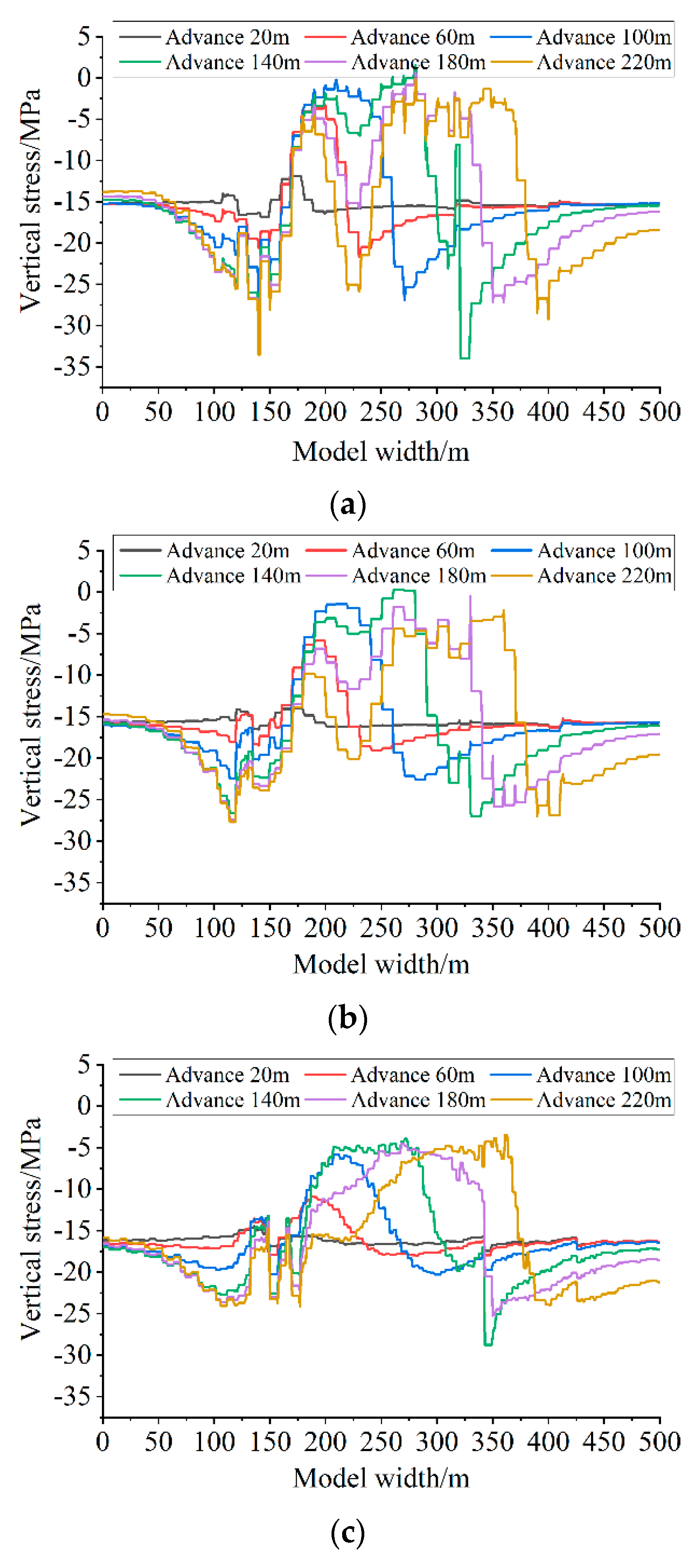
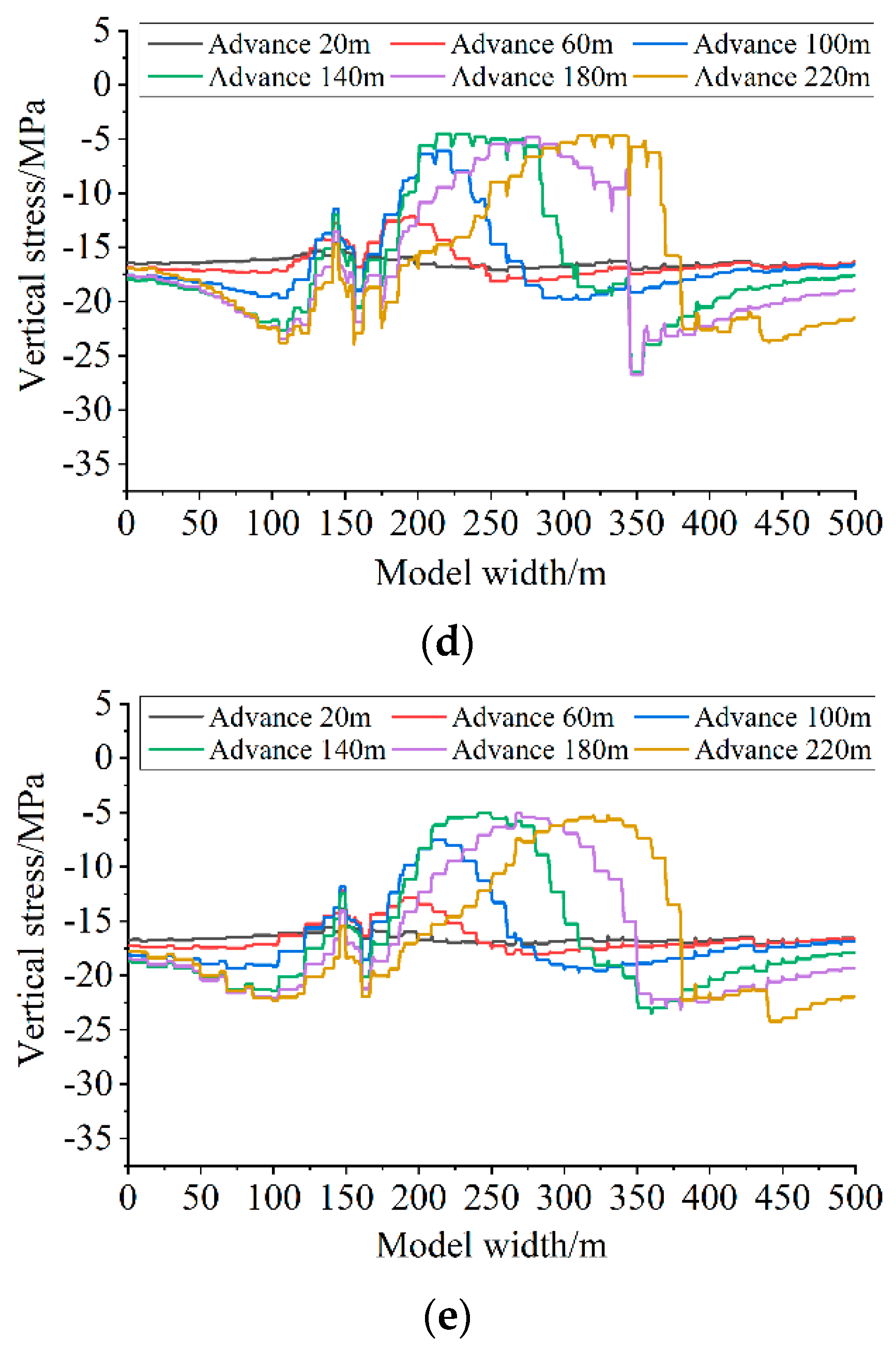
3.2. Analysis of Vertical Stress Evolution Characteristics

With the continuous advancement of the working face, the influence range of mining disturbance gradually expands, the original stress balance state in the roof and floor strata of the stope is changed, and the stress is redistributed, as shown in Figure 5. When the working face advances to 20 m, the stress concentration area is formed at the left and right ends of the goaf, and the pressure relief area is formed in the roof and floor, which is symmetrically distributed. The overall stress level at the fault is relatively low. When the working face advances by 60 m, the range of stress concentration area and pressure relief area increases, and the stress at the fault is at the same level as the stress at other positions of the model. When the working face advances by 100 m, the range of stress concentration area and pressure relief area further increases. At this time, a certain range of stress concentration area is formed at the fault below the left of the working face, and the pressure relief zone has entered the aquifer, which may lead to the connection between the mining cracks and the original cracks in the floor. Water in the limestone enters the working face along the connecting cracks, thereby affecting the safe and efficient recovery of the working face. When the working face advances 140 m, both the stress concentration area and the pressure relief area expand to the boundary position of the model. At this time, the cracks in the pressure relief area enter the Ordovician limestone layer, further increasing the probability of water inrush from the working face. When the working face advances 180 m, the pressure relief width in the coal seam floor further increases, and the probability of water inrush further increases. When the working face advances 220 m, except for the stress concentration areas at both ends of the goaf, the stress levels in other positions of the model are basically at the same low level. At this time, the pressure relief of the coal seam roof and floor is relatively sufficient, and the crack network is relatively dense, so the probability of water gushing in the working face is relatively high.
By extracting stress data from five monitoring lines on the coal seam floor, the evolution law of stress curves at different positions of the coal seam floor and at different working face advancing distances can be obtained, as shown in Figure 6. Line A is closer to the floor and has a higher vertical stress level. As the working face advances, the degree of stress concentration and its pressure relief range gradually increase, with the maximum concentrated stress reaching around 33 MPa and the pressure relief value reaching 0 MPa. There is local pressure relief and stress concentration at both ends of faults and original cracks. Starting from the advancement of the working face to 140 m, stress recovery began in the middle of the goaf. Therefore, as the working face advanced, local stress concentration occurred in the middle of the goaf and the corresponding coal seam floor. As the distance from the working face increases, the degree of pressure relief and stress concentration in the floor decrease, and the range of pressure relief decreases, with a pressure relief value of around −5 MPa.

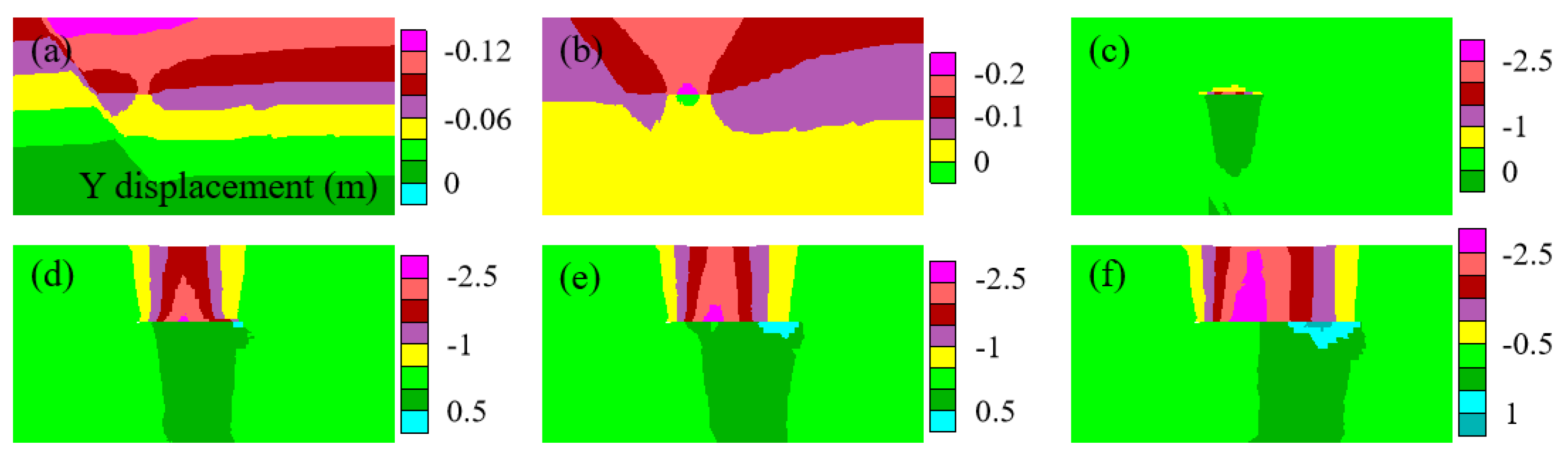
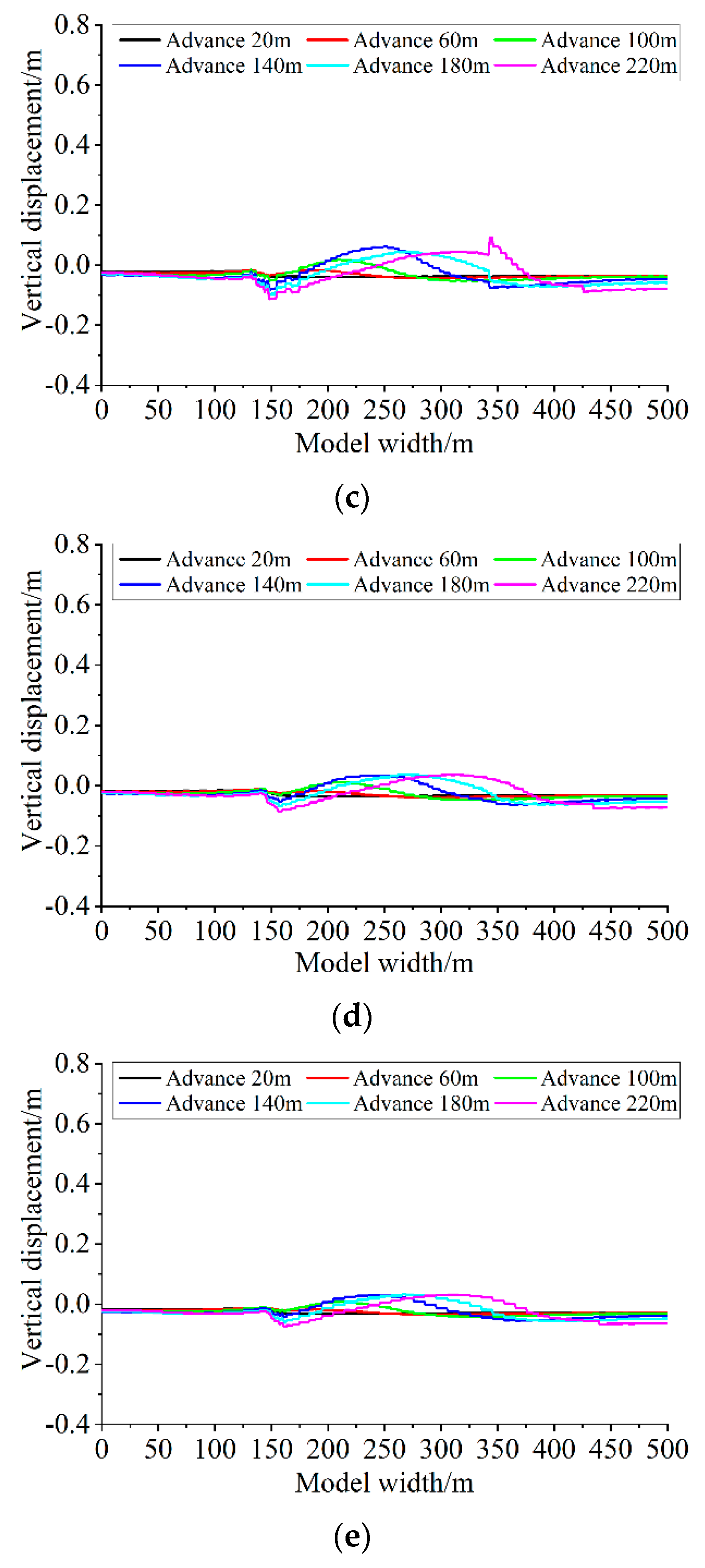
3.3. Analysis of Displacement Evolution Characteristics

Due to the extraction of coal, a goaf appeared in the original strata, and the surrounding rock moved towards the goaf due to the action of geostress. Due to the presence of a large fault on the left, different displacement characteristics are exhibited on both sides of the fault. As shown in Figure 7, when the working face advances by 20 m, the displacement stratification is obvious, and the overall displacement changes little except for the working face. When the working face advances by 60 m, the displacement stratification is not obvious, the coal seam roof displacement is large, and the floor moves upwards, resulting in a positive displacement. When the working face advances by 100 m, the positive displacement range of the floor expands; that is, the area where the floor moves upwards increases, the number of cracks increases, and the aquifer is affected, greatly increasing the probability of upward migration of confined water. When the working face advances by 140 m, the displacement of the roof shows a symmetrical strip distribution, and the range of positive displacement of the floor further increases, reaching the bottom boundary of the model. At the same time, it indicates that the Ordovician limestone aquifer also has an upward displacement, further increasing the range of the crack network. As the working face advances, the range of upward movement of the floor gradually increases, and a certain degree of floor heave is formed below the working face. At this time, there are hidden cracks connecting the aquifer below the floor heave, which will cause water inrush accidents in the working face.
By extracting displacement data from 5 monitoring lines of the floor, we can obtain the evolution law of displacement curves at different positions of the floor and different advancing distances, as shown in Figure 8. On line A, as the working face advances, the range and amplitude of the upward movement of the floor continue to increase. However, after advancing to 180 m, the goaf behind the working face is continuously compacted, and the upward displacement of the floor decreases. The maximum displacement near the working area is about 0.8 m, resulting in floor heave failure. In addition, the displacement of the fault continues to increase and move downwards as the working face advances. As the distance between the measuring line and the working face increases, the amplitude of displacement curve change becomes smaller; that is, the effect of mining on the working face is smaller, and the maximum displacement can also reach about 0.1 m. The cracks hidden in the floor, which provide favorable conditions for the water channel, are highly likely to cause water inrush accidents in the working face.

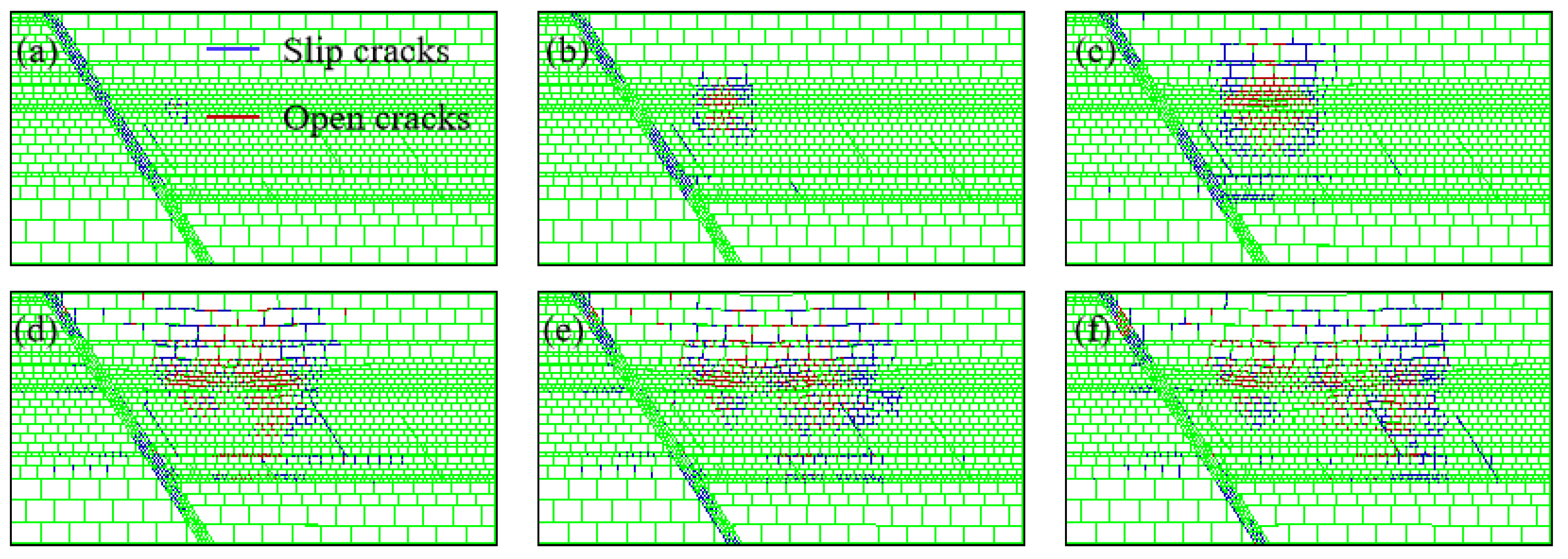
3.4. Analysis of Fracture Evolution Characteristics

Figure 9 shows the evolution law of geological fractures under different advancing distances of the working face, with red indicating open fractures and blue indicating slip fractures. When the working face advances by 20 m, the development range of roof and floor cracks is relatively small. Major faults and associated fractures nearby are activated. The fractures of major faults are particularly developed, and most of them are slip fractures at this time. As the working face advances by 60 m, the development range of roof and floor cracks gradually expands, and the hidden cracks between L10 limestone and L8 limestone are activated. Some cracks in the fault are compacted, and the number of open cracks increases at this time. When the working face advances by 100 m, the development range of roof and floor cracks continues to expand, and new cracks appear in the L10 limestone and its bottom on the right side of the major fault. The fault, hidden cracks, and aquifer limestone cracks initially formed a crack network, providing conditions for groundwater conductivity. When the working face advances by 140 m, the open cracks are more developed, and most of the hidden cracks are activated, forming a complex water channel, greatly increasing the probability of water gushing from the working face. As the working face continues to advance, hidden cracks are completely activated, the crack network further expands, and the number of open cracks increases; that is, there are more and more channels for groundwater to rise.

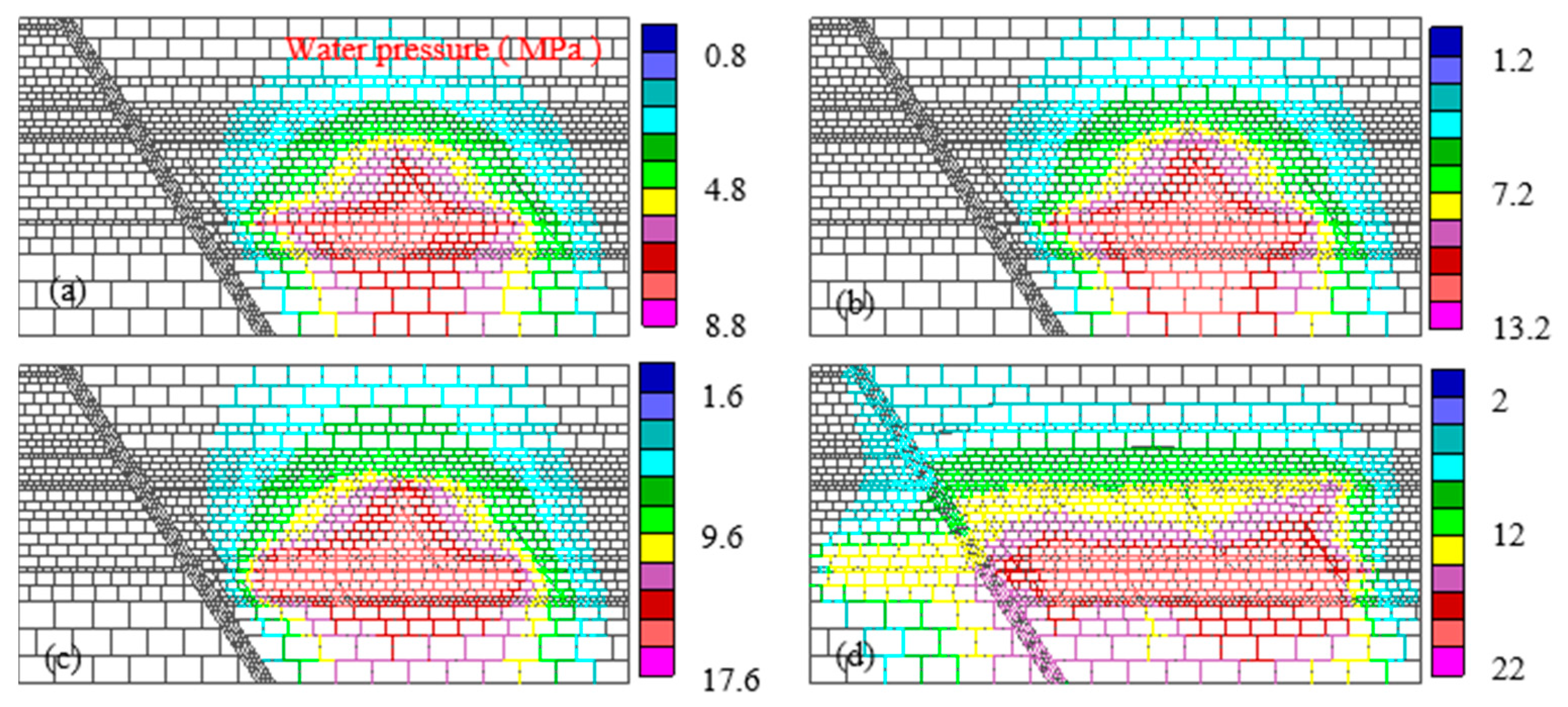
3.5. Evolution Characteristics of Plastic Zone and Seepage Analysis

Figure 10 shows the coupled evolution process between the plastic zone and seepage of the coal seam roof and floor. In the early stages of mining, L10 and L8 limestone water first enters faults and hidden cracks. Ordovician limestone water and other Taiyuan limestone water also flow to the faults, forming a crisscrossing groundwater system. At this point, the plastic zone of the coal seam roof and floor is relatively small and not connected to the water-bearing structure. As the working face continues to advance, the scope of the plastic zone continues to expand. The plastic zone of the floor is connected to some hidden cracks, and some groundwater begins to flow upwards along the hidden cracks. As the working face continues to advance, the number of hidden cracks connected with the plastic zone of the floor increases. The plastic zone of the floor develops above the aquifer. At that time, a large amount of high-pressure water begins to go upward and flow towards the working face, causing water hazard to the working face. This is consistent with the conclusions of many scholars [14,24,28], and the rationality of the numerical model in this paper is verified.
In summary, before coal seam mining, due to the balance between surrounding rock stress and water pressure, groundwater is in a balanced and static state after being guided to a certain height in the original fracture. After coal seam mining, the vertical stress of the overlying strata is released, causing the floor of the working face to be almost in a two-dimensional stress state. Under the action of high water pressure, the Ordovician limestone water and Taiyuan limestone water infiltrate, expand, fracture, and ascend along hidden and mining fractures, until they communicate with the coal seam floor failure zone, forming a large area of scattered water inrush. The technical measures and means of floor water inrush are mainly the transformation of floor aquifer, drainage and depressurization, mining under pressure, and reinforcement of floor aquiclude. Therefore, regional advanced grouting reinforcement technology is proposed to transform the aquifer in order to prevent the occurrence of mine water inrush accidents.

4. Numerical Simulation of Grouting in Coal Seam Floor

4.1. Model Establishment

Based on the previous analysis, a numerical model for grouting in the coal seam floor aquifer is established to analyze the effect of grouting. The parameters and boundary conditions used in the simulation are consistent with the water inrush mechanism model. According to actual grouting engineering statistics, the pressure of the initial fracturing approximately ranges from 8 MPa to 12 MPa. L10 limestone and L8 limestone were selected as the injection layers, and the grouting pressures at the borehole orifice were set to 0 MPa, 4 MPa, 8 MPa, and 12 MPa, respectively. When the slurry reached the injection target layer, due to the increase in the self-weight pressure of the slurry, the injection pressures of the simulated injection layer were set to 7.7 MPa, 11.7 MPa, 15.7 MPa, and 19.7 MPa, respectively. Eight simulation schemes were established.

4.2. Diffusion Law of L10 Grouting Slurry

Figure 11 shows the slurry expansion law of L10 limestone and surrounding strata under different grouting pressures. When the grouting pressure is 7.7 MPa, the grouting pressure around the grouting section is the highest. As the grouting progresses, the high-pressure slurry continuously flows towards the surrounding area. The farther away from the grouting section, the lower the pressure. The overall pressure distribution is affected by the hidden faults on the coal seam floor, and the pressure near the hidden faults is relatively high. Due to its close proximity, L8 limestone is subjected to a pressure greater than 7 MPa at the bottom of the grouting section. The original karst pores, fissures, and fracture channels near the grouting section that contain water were reinforced by grouting, and the previously closed joint fissures may also be split by high pressure and reinforced by grouting.
When the grouting pressure increases to 11.7 MPa, the pressure transmission range expands, and the coal seam is maximally affected by a grouting pressure of about 9 MPa. The L8 limestone and the aquifuge between L10 limestone are affected by a grouting pressure of about 11 MPa, indicating that the aquifuge of the coal seam floor and the karst holes, cracks, and fracture channels in the aquifer are fully grouted. The range of high-pressure fracturing cracks and grouting reinforcement expands. When the grouting pressure increases to 15.7 MPa, the pressure transmission range still presents a circular distribution. As the grouting pressure continues to increase, the influence range of the slurry becomes larger and the grouting effect becomes more pronounced. When the grouting pressure reaches 19.7 MPa, the slurry diffuses significantly to the left and right sides, and the left side extends to the large fault. Grouting reinforcement can be carried out in the fault fracture area. The grouting pressure gradually decreases from the bottom to the top, and the slurry also influences the left side of the fault and the coal seam roof. This indicates that the grouting pressure is too high, and it is necessary to adjust the pressure in a timely manner. It is recommended to maintain the grouting pressure at the orifice at around 8 MPa.

4.3. Diffusion Law of L8 Grouting Slurry

Figure 12 shows the slurry expansion law of L8 limestone and surrounding strata under different grouting pressures. When the grouting pressure is 7.7 MPa, the diffusion law of the slurry is basically consistent with L10, but the influence range of grouting is small, it does not reach the coal seam, and the grouting reinforcement effect is weakened. Due to the presence of hidden faults connecting L8 limestone and L10 limestone, L10 limestone is subjected to significant grouting pressure near this hidden fault, but the impact range is relatively small. When the grouting pressure is 11.7 MPa, the influence range of the slurry expands, and the coal seam is affected by the slurry at about 3.5 MPa. Slurry pressures above 8 MPa are mainly concentrated below the L8 limestone grouting section and near the hidden faults that connect with L10 limestone, and their influence range is limited. When the grouting pressure of L8 limestone is 15.7 MPa, the influence range of the slurry further expands. The coal seam is affected by the slurry at about 6 MPa. However, the grouting reconstruction range of L10 is limited, and the slurry above it presents a circular distribution. When the grouting pressure is 19.7 MPa, the high pressure of the slurry extends to the vicinity of the large fault, reaching around 8 MPa, which has a certain reinforcement effect on the fault. The slurry pressure in most areas below the coal seam on the right side of the major fault reaches over 14 MPa, indicating that most areas of the coal seam floor are split by grouting pressure, and the formed water channel is filled with slurry. The purpose of grouting reinforcement is achieved; therefore, it is recommended to maintain the grouting pressure at the orifice of this layer at around 12 MPa.

5. Engineering Applications
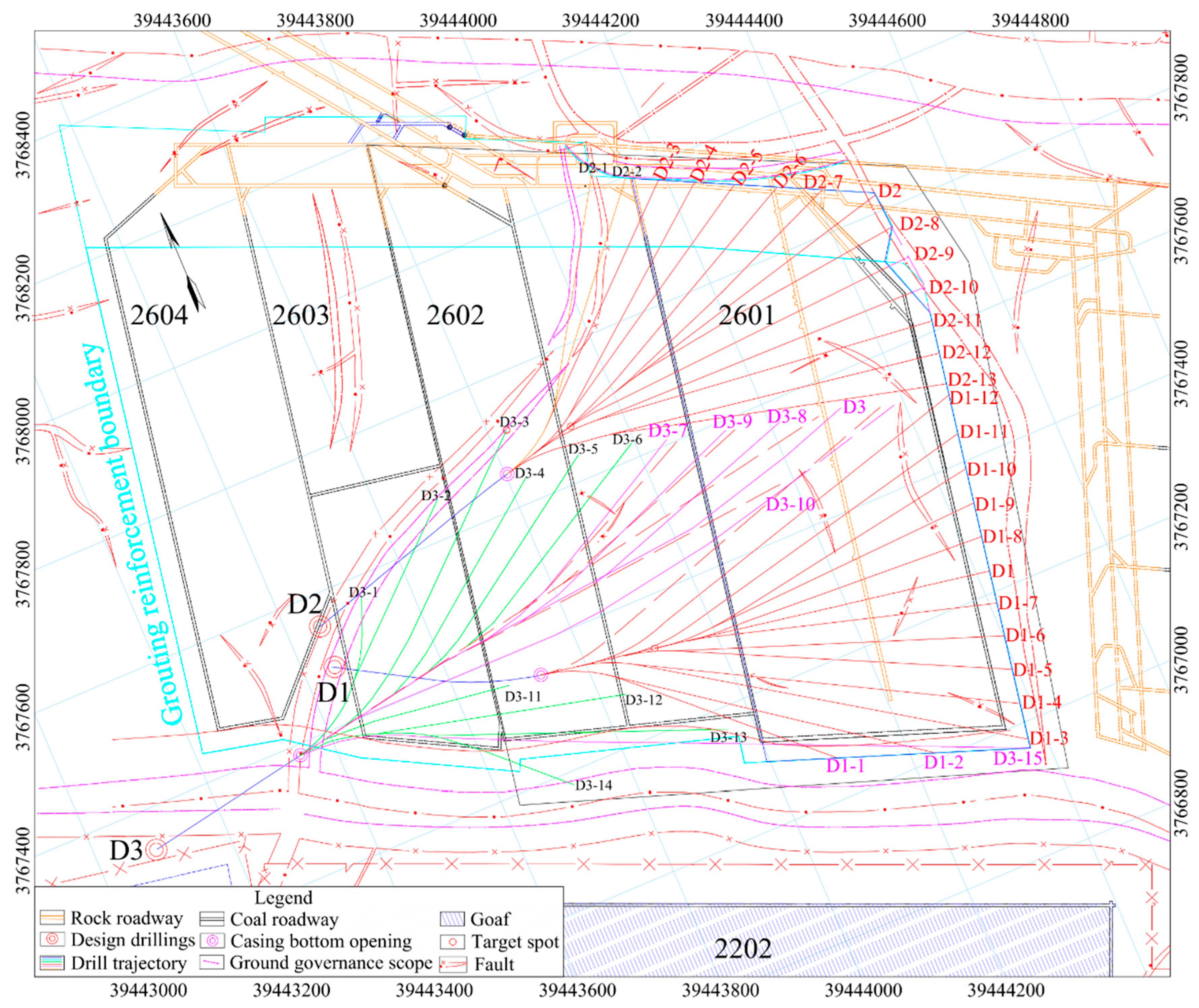
5.1. Grouting Plan

Through our data analysis and research, it can be seen that the main water-filled aquifer of the coal seam floor of the 2601 working face in the sixth mining area is the limestone (L11~L8) of the upper section of the Taiyuan Formation, and its water pressure is 5.7~6.5 MPa. The L10 limestone has many water outlet points and a large grouting volume. After the transformation, the effective aquifuge thickness is 70 m, and the water inrush coefficient meets the relevant requirements of the ‘Coal Mine Water Prevention and Control Rules’. According to the karst’s development and complexity as well as the water-rich characteristics of the limestone aquifer in the upper section of the Taiyuan Formation in the mining area, the selection of the L10 limestone as the treatment target layer not only ensures effects on the drilling treatment and grouting, but also helps realize the treatment of other limestone aquifers and water-conducting channels. Therefore, it is scientific and reasonable to choose the L10 limestone aquifer as the key stratum for grouting, which is also in line with engineering practice.
A total of three ground hole groups were constructed for the ground area management of Working Face 2601: three main holes and 28 branch holes. A comprehensive exploration and treatment of the working face were carried out with a 30 m expansion range. The cumulative drilling footage was 19,927.35 m, and the overall bedding rate was 96.06%. The schematic diagram of the drilling structure is shown in Figure 13, and the construction plan is shown in Figure 14. A total of 78 rounds of grouting were conducted, with 79,753 t of cement injected. The plane distribution of grouting is shown in Figure 15.

5.2. Effect Verification

5.2.1. Geophysical Verification

The transient electromagnetic method and three-dimensional DC resistivity method were used to verify the grouting effect of the 2601 working face. Among them, the transient electromagnetic method was used for two geophysical verifications. One was carried out in the implementation process of the control of the ground area, and the other was carried out at the end of the control of the ground area and the end of the underground drilling verification. A multi-angle construction exploration was carried out along the upper and lower crossheadings of the 2601 working face for both sides and the roadway floor. Before the grouting treatment, 22 abnormally low resistance areas were found in our exploration. After the grouting treatment, the apparent resistivity of the coal seam floor was high, and only a low-resistivity anomaly area of about 30 m appeared 380 m–410 m outside the 601 × 7 point of the return air trough of the 2601 working face (Figure 16). According to the detection results, the X3-Y1 and X3-Y2 holes are specially arranged in the underground to explore the abnormal area, and the water yield of the borehole is less than 10 m3/h. It shows that the aquifer fissure water storage space is reinforced by slurry filling, and the effect of the grouting reinforcement in the ground area is remarkable.
The three-dimensional DC resistivity method is used to arrange the measuring points along the upper and lower grooves of the 2601 working face, and a three-dimensional exploration of the water-rich floor after grouting is carried out. It is stipulated that the area with a resistivity less than 12 Ω·m is a low-resistance anomaly area. According to the geophysical results (Figure 17), it can be seen that there is only an area with a resistivity less than 12 Ω·m (the blue area in the figure) in the range of 280 m~360 m along the working face and 80 m~170 m in the inclination of the working face, and there are no obvious low-resistivity anomaly areas in other areas. In the three-dimensional resistivity anomaly area, underground boreholes are specially arranged for verification. The verification results show that there is no water leakage in the boreholes of the grouting target layer, which further proves that the grouting treatment’s effect on the ground area is more pronounced.

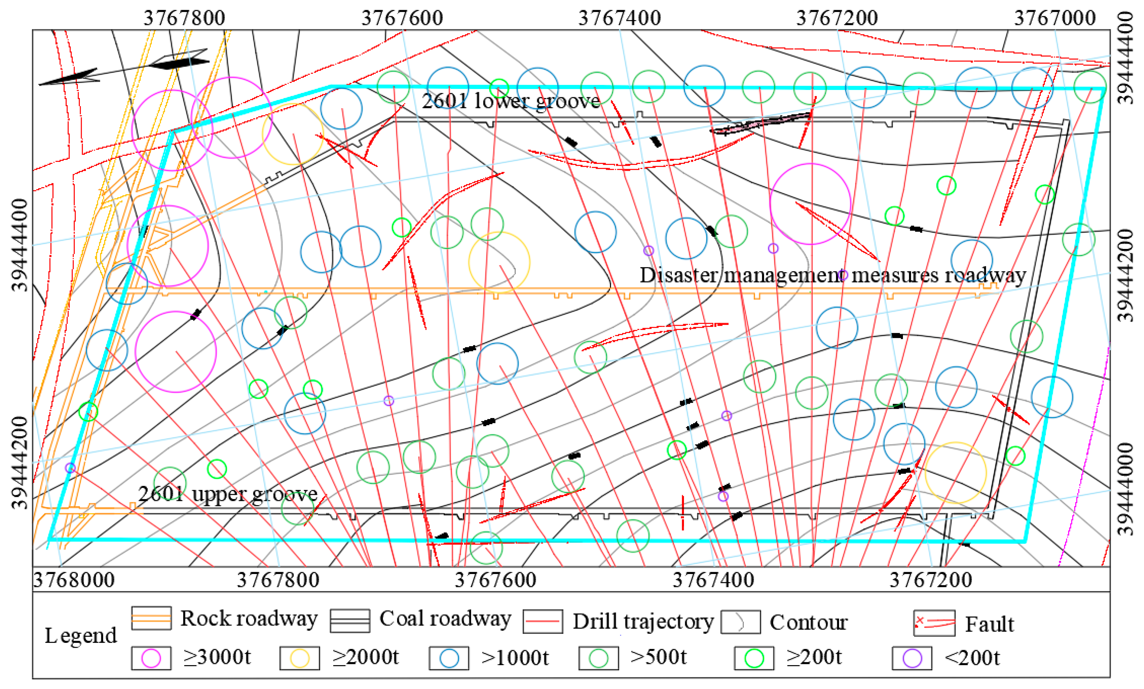
5.2.2. Drilling Verification

The 194 verification holes were constructed, of which 192 holes had an initial water inflow of less than 10 m3/h of the L10 limestone, accounting for 98.97%. Individual isolated water discharge points with an initial water inflow greater than 10 m3/h meet the requirement of being less than 10 m3/h for the underground supplementary treatment and verification.
So far, the 2601 working face has safely mined over 300 m and 500,000 tons of coal resources, without any water inrush. The effect of the reconstruction of the aquifer’s grouting is good.

6. Conclusions

Based on the specific geological conditions of the 2601 working face in the Chensilou mine, a combination of a numerical simulation and an on-site testing analysis method was carried out to study the mechanism of water inrush from the coal seam floor and grouting reinforcement technology during the mining process. The following conclusions were drawn.
(1)
The analysis of our on-site data shows that due to the influence of faults, hidden cracks, and water pressure, the upper part of the Taiyuan Formation aquifer in the Chensilou sixth mining area may have hydraulic connections with the Ordovician limestone aquifer, resulting in complex hydrogeological conditions in the mine. Among them, L10 and L8 are the main aquifers, with well-developed dissolution fractures.
(2)
As coal is mined, the vertical stress within the roof and floor of the mining area is redistributed, resulting in a concentration of stress in the coal and rock at both ends of the goaf, with a symmetrical distribution on both sides. A pressure relief zone was created within the roof and floor, causing it to move towards the goaf and form a certain degree of floor heave. During the movement process, a large number of open cracks and sliding cracks are generated in the roof and floor, causing plastic damage to the floor. After the activation of hidden faults and cracks, a water inrush channel on the floor is formed, causing water accidents in the working face. The numerical simulation results are consistent with the on-site water inrush situation, which can provide a basis for the effective transformation measures of the floor under complex hydrogeological conditions.
(3)
The grouting effect varies at different layers and pressures. For the 2601 working face of the Chensilou mine, when the L10 thin limestone is selected as the injection layer, the injection range gradually increases with the increase in injection pressure. However, an excessive injection pressure can easily cause slurry leakages and resource waste in the working face. Choosing a reasonable injection pressure is crucial. When the lower layer of the L8 thin limestone is selected for the injection layer, the diffusion law of the slurry is consistent with that of L10, but the injection pressure cannot be too small. If it is too small, the grouting reconstruction effect will not be obvious.
(4)
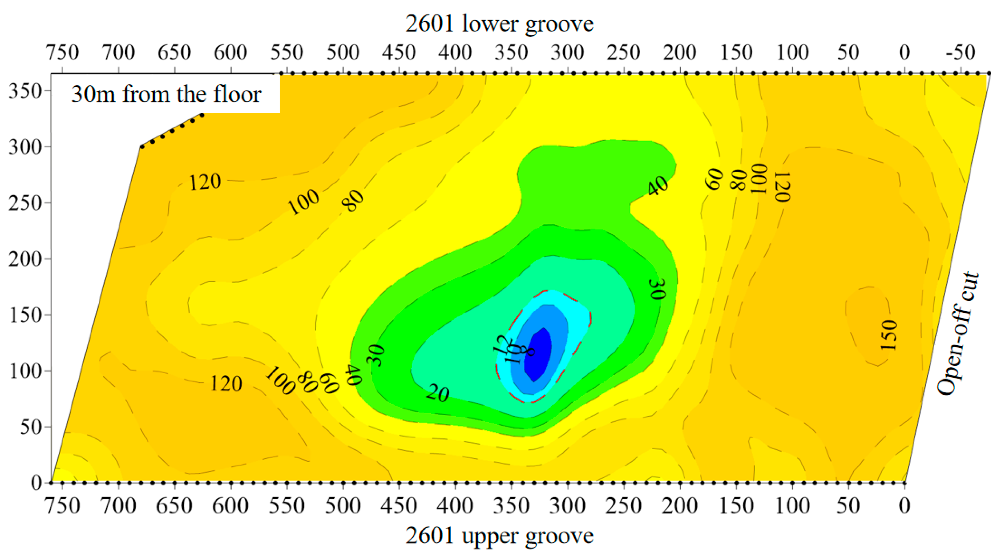
A geophysical verification of the effect of the reconstruction of the grouting was conducted underground using transient electromagnetic and three-dimensional direct-current resistivity methods. It indicates that the apparent resistivity of the coal seam floor after the treatment is relatively high, and there are only low-resistivity abnormal areas with a resistivity less than 12 Ω·m within the range of 280 m–360 m along the working face direction and 80 m–170 m towards the working face. However, there was no water outflow in the borehole, indicating that the aquifer’s fissure water storage space was filled and reinforced with slurry. Our use of ground regional advanced governance projects achieved significant results.
(5)
The research results have a certain value which is of theoretical and practical significance and can provide a reference for water hazard management in similar mines. Before grouting, the floor structure and the development of floor cracks during mining should be fully understood, and the possible water inrush channels should be identified. When grouting, an appropriate grouting layer and grouting pressure should be selected according to the actual situation of the site to avoid the phenomenon in which the grouting pressure is too large to cause the working face to run slurry or the grouting pressure is too small to diminish the transformation effect.

Author Contributions

Conceptualization, Q.W., S.Z., Z.S. and P.W.; methodology, Q.W., S.Z., Z.S., P.W. and H.L.; software, H.L.; writing—original draft preparation, H.L.; writing—review and editing, G.W.; project administration, Q.W., S.Z., Z.S. and P.W. All authors have read and agreed to the published version of the manuscript.

Funding

This research was funded by the National Key R&D Program of China: 2017YFC0804102.

Data Availability Statement

The data used to support the findings of this study are included within the article.

Conflicts of Interest

Author Qi Wang was employed by the company CCTEG Xi’an Research Institute (Group) Co., Ltd. The remaining authors declare that the research was conducted in the absence of any commercial or financial relationships that could be construed as a potential conflict of interest.

References

  1. Liu, W.T.; Wu, Q. Mechanism and Numerical Simulation Technology of Lagging Water Inrush in Deep Mining; Coal Industry Publishing House: Beijing, China, 2010; pp. 2–5. [Google Scholar]
  2. Zhang, W.Q.; Yang, C.G.; Jiang, P.W.; Zhang, H.R.; Kong, L.Z. Prevention and Control of Mine Water Disaster; China University of Mining and Technology Press: Xuzhou, China, 2008; pp. 20–80. [Google Scholar]
  3. Yubing, G.A.O.; Shiqi, L.I.U.; Bin, L.Y.U.; Kunqi, L.I. Mechanism study of floor water inrush around mining field based on micro-crack extension. J. Min. Saf. Eng. 2016, 33, 624–629. [Google Scholar]
  4. Li, L.C.; Tang, C.A.; Li, G.; Yang, T.H. Damage evolution and delayed groundwater inrush from micro faults in coal seam floor. Chin. J. Geotech. Eng. 2009, 31, 1838–1844. [Google Scholar]
  5. Zhao, J.W.; Zhou, H.W.; Xue, D.J.; Su, T.; Deng, H.L.; Yang, H.Z. Expansion law of seepage path in the concealed structural floor of coal seam in deep confined water. J. China Coal Soc. 2019, 44, 1836–1845. [Google Scholar]
  6. Pan, Y.B. An inquiry of secure hydraulic head formula of slisalif’s. J. Hefei Polytech. Univ. 1986, 8, 99–103. [Google Scholar]
  7. Li, B.Y. “Down three zones” in the prediction of the water inrush from coalbed floor aquifer-theory, development and application. J. Shandong Inst. Min. Technol. 1999, 18, 11–18. [Google Scholar]
  8. Liu, Q.S. A discussion on water inrush coefficient. Coal Geol. Explor. 2009, 37, 34–37. [Google Scholar]
  9. Wang, J.T.; Wang, X.L. Discussion on water inrush coefficient method applied to predict water inrush danger of seam floor. Coal Sci. Technol. 2011, 39, 106–111. [Google Scholar]
  10. Zhang, J.C.; Zhang, Y.Z.; Liu, T.Q. Rock Seepage and Water Inrush of Seam Floor; Geological Press: Beijing, China, 1997. [Google Scholar]
  11. Xing, Z.G.; Li, B.Y. Mechanism of water inrush in coal seam floor. Coal Geol. Explor. 1980, 2, 27–29. [Google Scholar]
  12. Li, B.Y.; Er, S.Z. Mining Engineering Hydrogeology; Shandong Institute of Mining and Technology Press: Tai’an, China, 1988. [Google Scholar]
  13. Wang, Z.Y.; Liu, H.Q. Coal Mining above Confined Aquifer; Coal Industry Press: Beijing, China, 1992. [Google Scholar]
  14. Qian, M.G.; Miao, X.X.; Xu, J.L. Theoretical study of key stratum in ground control. J. China Coal Soc. 1996, 21, 225–230. [Google Scholar]
  15. Hu, X.; Wang, L.; Lu, Y.; Yu, M. Analysis of insidious fault activation and water inrush from the mining floor. Int. J. Min. Sci. Technol. 2014, 24, 477–483. [Google Scholar] [CrossRef]
  16. Peng, S.P.; Meng, Z.P.; Li, Y.L. Influence of faults on coal roof stability by physical modeling study. Coal Geol. Explor. 2001, 29, 1–4. [Google Scholar]
  17. Zuo, J.P.; Chen, Z.H.; Wang, H.W.; Liu, X.P.; Wu, Z.P. Experimental investigation on fault activation pattern under deep mining. J. China Coal Soc. 2009, 34, 305–309. [Google Scholar]
  18. Li, Z.H.; Dou, L.M.; Lu, Z.Y.; Lu, X.W.; Wang, G.R. Study of the fault slide destabilization induced by coal mining. J. Min. Saf. Eng. 2010, 27, 499–504. [Google Scholar]
  19. Li, K.; Mao, X.B.; Chen, L.; Zhang, L.Y. Research on fault activation and risk analysis of water inrush in mining floor above confined aquifer. Chin. Q. Mech. 2011, 32, 261–268. [Google Scholar]
  20. Liu, Z.J.; Hu, Y.Q. Solid-liquid coupling study on water inrush through faults in coal mining above confined aquifer. J. China Coal Soc. 2007, 32, 1046–1050. [Google Scholar]
  21. Zheng, S.H.; Zhu, W.S.; Wang, S.F. Study on the coupling problem between flow and solid of mine in confined aquifer. Chin. J. Rock Mech. Eng. 2000, 19, 421–424. [Google Scholar] [CrossRef]
  22. Zhang, P.; Yan, W.; Zhang, W.; Wang, H. Experimental research on fault activation and water inrush induced by mining under solid-liquid coupling mode. Saf. Coal Mines 2014, 45, 24–27. [Google Scholar]
  23. Zhang, P.; Yan, W.; Zhang, W.; Wang, H. Analysis of Water Inrush Disaster Mechanism of Inter-Layer Rocks between Close Coal Seams under the Influence of Mining. Appl. Sci. 2023, 13, 9043. [Google Scholar] [CrossRef]
  24. Liu, Y.; Liu, S.; Huo, Z.; Sun, K.; Wang, T.; Li, W. Failure Characteristics of Coal Seam Floor and Risk Assessment of Water Inrush Caused by Underground Coal Mining. Energy Explor. Exploit. 2023, 41, 677–695. [Google Scholar] [CrossRef]
  25. Yang, T.H.; Tang, C.A.; Xu, T. Flow Characteristics during Rock Failure Process-Theory, Models and Applications; Science Press: Beijing, China, 2004. [Google Scholar]
  26. Yang, T.H.; Liu, J.; Zhu, W.C.; Elsworth, D.; Tham, L.G.; Tang, C.A. A coupled flow-stress-damage model for groundwater outbursts from an underlying aquifer into mining excavations. Int. J. Rock Mech. Min. Sci. 2007, 44, 87–97. [Google Scholar] [CrossRef]
  27. Song, W.; Liang, Z. Theoretical and numerical investigations on mining-induced fault activation and groundwater outburst of coal seam floor. Bull. Eng. Geol. Environ. 2021, 80, 5757–5768. [Google Scholar] [CrossRef]
  28. Yin, H.; Sang, S.; Xie, D.; Zhao, H.; Li, S.; Li, H.; Zhuang, X. A numerical simulation technique to study fault activation characteristics during mining between fault bundles. Environ. Earth Sci. 2019, 78, 1–11. [Google Scholar] [CrossRef]
  29. Xin, C.; Jiang, F.; Zhai, C.; Chen, Y. Analysis of Coal Floor Fault Activation Inducing Water Inrush Using Microseismic Monitoring—A Case Study in Zhaogu No. 1 Coal Mine of Henan Province, China. Sustainability 2023, 15, 7361. [Google Scholar] [CrossRef]
  30. Hu, Y.; Sun, J.; Liu, W.; Wei, D. The evolution and prevention of water inrush due to fault activation at working face no. II 632 in the Hengyuan coal mine. Mine Water Environ. 2019, 38, 93–103. [Google Scholar] [CrossRef]
  31. Li, H.; Bai, H. Simulation research on the mechanism of water inrush from fractured floor under the dynamic load induced by roof caving: Taking the Xinji Second Coal Mine as an example. Arab. J. Geosci. 2019, 12, 1–24. [Google Scholar] [CrossRef]
  32. Yu, H.; Zhu, S.; Xie, H.; Hou, J. Numerical simulation of water inrush in fault zone considering seepage paths. Nat. Hazards 2020, 104, 1763–1779. [Google Scholar] [CrossRef]
  33. Itasca. UDEC, Version 6.0; Itasca Consulting Group Inc.: Minneapolis, MN, USA, 2014.
Figure 1. North/south longitudinal section of mining area 6.
Processes 11 03319 g001
Figure 2. General process of static analysis.
Processes 11 03319 g002
Figure 3. Geometric dimensions of the model.
Processes 11 03319 g003
Figure 4. Numerical model.
Processes 11 03319 g004
Figure 5. Vertical stress evolution law of working face and its roof and floor. (a) working face advancing 20 m, (b) working face advancing 60 m, (c) working face advancing 100 m, (d) working face advancing 140 m, (e) working face advancing 180 m, and (f) working face advancing 220 m.
Processes 11 03319 g005
Figure 6. Vertical stress evolution curve of floor during advancing process of working face. (a) The stress evolution law on line A. (b) The stress evolution law on line B. (c) The stress evolution law on line C. (d) The stress evolution law on line D. (e) The stress evolution law on line E.
Processes 11 03319 g006aProcesses 11 03319 g006b
Figure 7. Evolution law of vertical displacement of working face and its roof and floor. (a) working face advancing 20 m, (b) working face advancing 60 m, (c) working face advancing 100 m, (d) working face advancing 140 m, (e) working face advancing 180 m, and (f) working face advancing 220 m.
Processes 11 03319 g007
Figure 8. Vertical displacement evolution curve of floor during advancing process of working face. (a) The displacement evolution law on line A. (b) The displacement evolution law on line B. (c) The displacement evolution law on line C. (d) The displacement evolution law on line D. (e) The displacement evolution law on line E.
Processes 11 03319 g008aProcesses 11 03319 g008b
Figure 9. Crack evolution law of roof and floor. (a) working face advancing 20 m, (b) working face advancing 60 m, (c) working face advancing 100 m, (d) working face advancing 140 m, (e) working face advancing 180 m, and (f) working face advancing 220 m.
Processes 11 03319 g009
Figure 10. Evolution characteristics of plastic zone and water inrush channel on roof and floor. (a) working face advancing 20 m, (b) working face advancing 60 m, (c) working face advancing 100 m, (d) working face advancing 140 m, (e) working face advancing 180 m, and (f) working face advancing 220 m.
Processes 11 03319 g010
Figure 11. Evolution characteristics of plastic zone and water inrush channel in roof and floor. (a) Water pressure is 7.7 MPa, (b) Water pressure is 11.7 MPa, (c) Water pressure is 15.7 MPa, (d) Water pressure is 19.7 MPa.
Processes 11 03319 g011
Figure 12. Evolution characteristics of plastic zone and water inrush channel in roof and floor. (a) Water pressure is 7.7 MPa, (b) Water pressure is 11.7 MPa, (c) Water pressure is 15.7 MPa, (d) Water pressure is 19.7 MPa.
Processes 11 03319 g012
Figure 13. Schematic diagram of drilling structure.
Processes 11 03319 g013
Figure 14. Construction plan.
Processes 11 03319 g014
Figure 15. Distribution of grouting situation.
Processes 11 03319 g015
Figure 16. Comparison of geophysical anomaly areas before and after the treatment of 2601 working face.
Processes 11 03319 g016
Figure 17. Results of 3D apparent resistivity method.
Processes 11 03319 g017
Table 1. Mechanical parameters of coal and rock masses.
NumberLithologyDensity (kg/m3)Bulk Modulus (kPa)Shear Modulus (kPa)Cohesion (kPa)Tensile Strength (kPa)Friction Angle (°)
1Mudstone230010 × 1067 × 1063.2 × 1032.4 × 10325
2Coal13007 × 1064 × 1061.2 × 1031.5 × 10322
3Fine sandstone250015 × 10611 × 1062.8 × 1033.1 × 10330
4Siltstone230013 × 1069 × 1063.4 × 1032.6 × 10326
5Sandy mudstone240011 × 1067 × 1062.7 × 1033.3 × 10332
6L10, L8, L3, L2240015 × 1068 × 1063.3 × 1032.9 × 10332
7Ordovician limestone250020 × 10612 × 1063.6 × 1033.2 × 10335
8Fault9004 × 1062 × 1061.8 × 1030.8 × 10326
Table 2. Mechanical parameters of joints.
NumberJoint TypeNormal Stiffness (kPa/m)Tangential Stiffness (kPa/m)Friction Angle (°)Cohesion (kPa)Permeability Constant (Pa−1·s−1)Initial Gap Width (m)Residual Gap Width (m)
1Mudstone3.5 × 1061.5 × 106260.05 × 103301 × 10−30.5 × 10⁻³
2Coal2 × 1061 × 106150.1 × 103---
3Fine sandstone3.3 × 1061.4 × 106211.0 × 103---
4Siltstone5.4 × 1062.2 × 106320.7 × 103---
5Sandy mudstone4 × 1062 × 106211.6 × 103---
6L10, L8, L3, L212 × 1066 × 106150.1 × 103300.1 × 10−30.05 × 10⁻³
7Ordovician limestone12 × 1066 × 106150.1 × 1031000.2 × 10−30.1 × 10⁻³
8Fault3.5 × 1061.5 × 106260.05 × 1033001 × 10−30.5 × 10⁻³
9Crack3.5 × 1061.5 × 106260.05 × 1031001 × 10−30.5 × 10⁻³
Disclaimer/Publisher’s Note: The statements, opinions and data contained in all publications are solely those of the individual author(s) and contributor(s) and not of MDPI and/or the editor(s). MDPI and/or the editor(s) disclaim responsibility for any injury to people or property resulting from any ideas, methods, instructions or products referred to in the content.

