
Alternative Options for Ebullated Bed Vacuum Residue Hydrocracker Naphtha Utilization

 ,
,  , , ,
, , , 
Abstract
:
1. Introduction
2. Materials and Methods
3. Results
4. Discussion
5. Conclusions
Supplementary Materials
Author Contributions
Funding
Data Availability Statement
Acknowledgments
Conflicts of Interest
Nomenclature
| A | Aromatics |
| ABD | Average bulk density |
| APS | Average particle size |
| BHT | 2,6-bis(1,1-dimethylethyl)-4-methylphenol |
| C2-T | C2 (dimethyl and ethyl) thiophenes |
| DES | Diethyl sulfide |
| DMS | Dimethyl sulfide |
| EDXRF | Energy dispersive X-ray fluorescent spectrometer |
| EN | European Standards |
| EtSH | Ethyl mercaptane |
| FBP | Final boiling point |
| FCC | Fluid catalytic cracking |
| FCCU | Fluid catalytic cracking unit |
| HCO | Light cycle oil |
| HDN | Hydrodenitrogenation |
| HDS | Hydrodesulphurization |
| HT | Hydrotreated |
| IBP | Initial boiling point |
| LCO | Light cycle oil |
| LBV | Linear-by volume |
| LHSV | Liquid hourly space velocity |
| LNB | LUKOIL Neftohim Burgas |
| LP | Linear programming |
| LPG | Liquid petroleum gas |
| MAV | Maleic anhydride value |
| MON | Motor octane number of gasoline |
| MTBE | Methyl tertiary butyl ether |
| N | Naphthenes |
| PIANO | Paraffins, iso-paraffins, aromatics, naphthenes, olefins |
| RE | Rare earth elements |
| RON | Research octane number of gasoline |
| SHU | Selective hydrogenation reactor |
| SLO | Slurry oil |
| VGO | Vacuum gas oil |
| VRHN | Vacuum residue hydrocracker naphtha |
| 1-PrSH | 1-propyl mercaptane |
| 2-MT | 2-methyl thiophene |
| 2-M-PrSH-2 | 2-methil-propyl mercaptane-2 |
| 2-PrSH | 2-propyl mercaptane |
| 3-MT | 3-methyl thiophene |
References
- 2023 World Oil Outlook 2045. OPEC Secretariat, October 2023 Helferstorferstrasse 17 A-1010 Vienna, Austria. ISBN 978-3-9504890-6-4. Available online: www.opec.org (accessed on 4 December 2023).
- Wang, Z.; Li, S.; Jin, Z.; Li, Z.; Liu, Q.; Zhang, K. Oil and gas pathway to net-zero: Review and outlook. Energy Strategy Rev. 2023, 45, 101048. [Google Scholar] [CrossRef]
- Gautam, R.; AlAbbad, M.; Guevara, E.R.; Sarathy, S.M. On the products from the pyrolysis of heavy fuel and vacuum residue oil. JAAP 2023, 173, 106060. [Google Scholar] [CrossRef]
- Bozuwa, J.; Burke, M.; Cox, S.; Skandierd, C.S. Chapter 8. Democratic governance of fossil fuel decline. In Energy Democracies for Sustainable Futures, 1st ed.; Nadesan, M., Pasqualetti, M.J., Keahey, J., Eds.; Elsevier Inc.: Amsterdam, The Netherlands, 2022; pp. 73–82. [Google Scholar]
- Muhammed, N.S.; Gbadamosi, A.O.; Epelle, E.I.; Abdulrasheed, A.A.; Haq, B.; Patil, S.; Al-Shehri, D.; Kamal, M.S. Hydrogen production, transportation, utilization, and storage: Recent advances towards sustainable energy. J. Energy Storage 2023, 73, 109207. [Google Scholar] [CrossRef]
- Kaiser, M.J.; De Klerk, A.; Gary, J.H.; Handwerk, G.E. Petroleum Refining. Technology, Economics, and Markets, 6th ed.; CRC Press: Boca Raton, FL, USA, 2020. [Google Scholar]
- Larson, M. Bottom of the Barrel Conversions: What Does the Future Hold? Available online: https://refiningcommunity.com/bottom-of-the-barrel-conversions-what-does-the-future-hold/ (accessed on 26 October 2023).
- Stratiev, D.; Shishkova, I.; Dinkov, R.; Dobrev, D.; Argirov, G.; Yordanov, D. The Synergy between Ebullated Bed Vacuum Residue Hydrocracking and Fluid Catalytic Cracking Processes in Modern Refining—Commercial Experience; Prof. Marin Drinov Publishing House of Bulgarian Academy of Sciences: Sofia, Bulgaria, 2022; ISBN 978-619-245-234-6. [Google Scholar]
- Pham, D.V.; Nguyen, N.T.; Kang, K.H.; Seo, P.W.; Yun, D.; Phan, P.D.; Park, Y.-K.; Park, S. Comparative study of single- and two-stage slurry-phase catalytic hydrocracking of vacuum residue for selective conversion of heavy oil. Catal. Today 2024, 426, 114391. [Google Scholar] [CrossRef]
- Wang, Y.; Lu, J.; Zhang, X.; Zhang, X.; Zhang, B.; Wu, J.; Guan, D.; Zhang, Y.; Chen, J.; Feng, X.; et al. Molecular transformation of heavy oil during slurry phase hydrocracking process: A comparison between thermal cracking and hydrocracking. Fuel 2023, 351, 128981. [Google Scholar] [CrossRef]
- ASTM D156-15; Standard Test Method for Saybolt Color of Petroleum Products (Saybolt Chromometer Method). ASTM: West Conshohocken, PA, USA, 2023.
- Pang, W.; Lee, J.K.; Yoon, S.H.; Mochida, I.; Ida, T.; Ushio, M. Compositional analysis of deasphalted oils from Arabian crude and their hydrocracked products. FPT 2010, 91, 1517–1524. [Google Scholar] [CrossRef]
- Karaba, A.; Dvořáková, V.; Patera, J.; Zámostnýa, P. Improving the steam-cracking efficiency of naphtha feedstocks by mixed/separate processing. JAAP 2020, 146, 104768. [Google Scholar] [CrossRef]
- Armstrong, M.; Brandt, M. Strategies for Improved Naphtha Processing, Revamps 2013, 1–10. Available online: www.digitalrefining.com/article/1000881 (accessed on 4 December 2023).
- Ramakumar, K.R.; Orman, S.; Kara, I.B. Pre-Reformer Catalyst in a Hydrogen Plant. Catalysis 2020, 1–4. Available online: www.digitalrefining.com/article/1002420 (accessed on 4 December 2023).
- Bittencourt, R.C.P.; Bidart, A.M.F.; Passarelli, F.M. A Process for Pre-Reforming Hydrocarbon Streams Containing Olefins, Pre-Reforming Catalyst and a Process for Preparing Sad. Catalyst. Patent US 2015/0315019 A1, 5 November 2015. [Google Scholar]
- Ershov, M.A.; Grigorieva, E.V.; Abdellatief, T.M.M.; Kapustin, V.M.; Abdelkareem, M.A.; Kamil, M.; Olabi, A.G. Hybrid low-carbon high-octane oxygenated gasoline based on low-octane hydrocarbon fractions. Sci. Total Environ. 2021, 756, 142715. [Google Scholar] [CrossRef]
- Palos, R.; Gutierrez, A.; Fernandez, M.L.; Azkoiti, M.J.; Bilbao, J.; Arandes, J.M. Taking advantage of the excess of thermal naphthas to enhance the quality of FCC unit products. J. Anal. Appl. Pyrolysis 2020, 152, 104943. [Google Scholar] [CrossRef]
- Usmanov, M.R.; Batyrov, N.A.; Galimov, Z.F.; Khairullin, R.N.; Bilalov, R.T. Treatment of visbreaker naphtha fraction by oligomerization. Chem Technol Fuels Oils 1999, 35, 4–6. [Google Scholar] [CrossRef]
- Pérez-Romoa, P.; Aguilar-Barreraa, C.; Navarrete-Bolanosa, J.; Rodríguez-Otal, L.M.; Beltrána, F.H.; Fripiat, J. Silica poisoning in HDT catalysts by light coker naphtha. Appl. Catal. A: Gen. 2012, 449, 183–187. [Google Scholar] [CrossRef]
- Perez-Romo, P.; Aguilar-Barrera, C.; Laredo, G.C.; Angeles-Chavez, C.; Fripiat, J. Novel solution for removing poisonous silica from a Ni-Mo/Al2O3 industrial HDT spent catalyst. Appl. Catal. A Gen. 2021, 611, 117964. [Google Scholar] [CrossRef]
- Breivik, R.; Egebjerg, R. Coker Naphtha Hydrotreating. PTQ, 2008, Q1, 1–7. Available online: www.digitalrefining.com/article/1000153 (accessed on 4 December 2023).
- Arandes, I.T.J.M.; Olazar, M.J.A.M.; Bilbao, J. Cracking of Coker Naphtha with Gas-Oil. Effect of HZSM-5 Zeolite Addition to the Catalyst. Energy Fuels 2007, 21, 11–18. [Google Scholar]
- Palos, R.; Gutiérrez, A.; Fernández, M.L.; Trueba, D.; Bilbao, J.; Arandes, J.M. Upgrading of heavy coker naphtha by means of catalytic cracking in refinery FCC unit. FPT 2020, 205, 106454. [Google Scholar] [CrossRef]
- Laredo, G.C.; Cano, J.C.; López, C.R.; Martin, R.S.; María, C.; Martínez, M.C.; Marroquín, J.O. Alternate use of heavy hydrotreatment and visbreaker naphthas by incorporation into diesel. FPT 2007, 88, 897–903. [Google Scholar] [CrossRef]
- Hui, C.; Jiasong, Y.; Youyou, S.; Xueer, W.; Rui, L.; Peng, W.; Shanqing, Y.; Zhenyu, D. Mechanistic Insights into the Catalytic Cracking of Cyclohexane. China Pet. Process. Petrochem. Technol. 2022, 24, 12–20. [Google Scholar]
- Xueyan, J.; Kui, Z.; Yuanbing, X.; Zhe, W.; Hong, N. Kinetic Model of LCO Selective Hydrogenation on NiMoW/Al2O3 Catalyst. China Pet. Process. Petrochem. Technol. 2022, 24, 1–9. [Google Scholar]
- Fu, Z.; Tongjiu, Z.; Yonggang, X.; Jiangyin, L. Application of Acid Modified Catalysts with Different SiO2 Contents in the Hydrocracking of Light Cycle Oil for Light Aromatics Production. China Pet. Process. Petrochem. Technol. 2023, 25-1, 105–114. [Google Scholar]
- Goosens, A.G. Prediction of molecular weight of petroleum fractions. Ind. Eng.Chem. Res. 1996, 35, 985–988. [Google Scholar] [CrossRef]
- ASTM D4052-22; Standard Test Method for Density, Relative Density, and API Gravity of Liquids by Digital Density Meter. ASTM: West Conshohocken, PA, USA, 2022.
- ASTM D4294-21; Standard Test Method for Sulfur in Petroleum and Petroleum Products by Energy Dispersive X-ray Fluorescence Spectrometry. ASTM: West Conshohocken, PA, USA, 2021.
- ASTM UOP326-07; Diene Value by Maleic Anhydride Addition Reaction. ASTM: West Conshohocken, PA, USA, 2007.
- Bouchy, C.; Picard, F.; Marchal, N. Selective Hydrogenation Process Employing a Catalyst Having a Controlled Porosity. Patent US7718053B2, 18 May 2010. [Google Scholar]
- ASTM D5134-21; Standard Test Method for Detailed Analysis of Petroleum Naphthas through n-Nonane by Capillary Gas Chromatography. ASTM: West Conshohocken, PA, USA, 2021.
- ASTM D5623-19; Standard Test Method for Sulfur Compounds in Light Petroleum Liquids by Gas Chromatography and Sulfur Selective Detection. ASTM: West Conshohocken, PA, USA, 2019.
- ASTM D2699-21; Standard Test Method for Research Octane Number of Spark-Ignition Engine Fuel. ASTM: West Conshohocken, PA, USA, 2021.
- ASTM D2700-22; Standard Test Method for Motor Octane Number of Spark-Ignition Engine Fuel. ASTM: West Conshohocken, PA, USA, 2022.
- Stratiev, D.; Toteva, V.; Shishkova, I.; Nenov, S.; Pilev, D.; Atanassov, K.; Bureva, V.; Vasilev, S.; Stratiev, D.D. Industrial Investigation of the Combined Action of Vacuum Residue Hydrocracking and Vacuum Gas Oil Catalytic Cracking While Processing Different Feeds and Operating under Distinct Conditions. Processes 2023, 11, 3174. [Google Scholar] [CrossRef]
- Stratiev, D.; Yankov, V.; Shishkova, I.; Chavdarov, I.; Petkov, P.; Palichev, T. Opportunity to produce near zero sulphur gasoline and improve refining profitability by combination of the processes fluid catalytic cracking feed hydrotreatment and gasoline post treatment. OGEM 2013, 4, 200–206. [Google Scholar]
- Largeteau, D.; Ross, J.; Laborde, M.; Wisdom, L. Challenges and opportunities of 10 ppm sulphur gasoline: Part 1. PTQ 2012, Q3, 1–10. [Google Scholar]
- Largeteau, D.; Ross, J.; Laborde, M.; Wisdom, L. Challenges and opportunities of 10 ppm sulphur gasoline: Part 2. PTQ 2012, Q4, 1–5. [Google Scholar]
- Namazifar, Z.; Saadati, F.; Miranbeig, A.A. Synthesis and characterization of novel phenolic derivatives with the glycerol ketal group as an efficient antioxidant for gasoline stabilization. N. J. Chem. 2019, 43, 10038–10044. [Google Scholar] [CrossRef]
- ASTM D 2892-20; Standard Test Method for Distillation of Crude Petroleum (15-Theoretical Plate Column). ASTM: West Conshohocken, PA, USA, 2023.
- Petrov, I.; Stratiev, D.; Shishkova, I.; Yordanov, D. A hybrid reformer performance analysis reveals the reason for reformate octane deterioration. OGEM 2021, 47, 14–20. [Google Scholar]
- Badra, J.; Alowaid, F.; Alhussaini, A.; Alnakhli, A.; AlRamadan, A.S. Understanding of the octane response of gasoline/MTBE blends. Fuel 2022, 318, 123647. [Google Scholar] [CrossRef]
- EN 228:2012+A1:2017; Automotive Fuels—Unleaded Petrol—Requirements and Test Methods (Includes Amendment 2017). European Committee for Standardization: Brussels, Belgium,, 2017.
- Nagpal, J.M.; Joshi, G.C.; Rastogi, S.N. Stability of cracked naphthas from thermal and catalytic processes and their additive response. Part I. Evaluation of stability and additive response. Fuel 1995, 74, 714–719. [Google Scholar] [CrossRef]
- Pereira, R.C.C.; Pasa, V.M.D. Effect of mono-olefins and diolefins on the stability of automotive gasoline. Fuel 2006, 85, 1860–1865. [Google Scholar] [CrossRef]
- Medeiros, E.A.; Nicodem, D.E.; Corrêa, R.J. A new fast methodology to measure total diene content in gasoline. Fuel 2011, 90, 1696–1699. [Google Scholar] [CrossRef]
- Gieleciak, R.; Hall, A.; Michaelian, K.; Chen, J. Exploring the Potential of Raman Spectroscopy for Characterizing Olefins in Olefin-Containing Streams. Energy Fuels 2023, 37, 13698–13709. [Google Scholar] [CrossRef]
- Abdellatief, T.M.M.; Ershov, M.A.; Kapustin, V.M.; Chernysheva, E.A.; Mustafa, A. Low carbon energy technologies envisaged in the context of sustainable energy for producing high-octane gasoline fuel. Sustain. Energy Technol. Assess. 2023, 56, 103103. [Google Scholar] [CrossRef]
- Abdellatief, T.M.M.; Ershov, M.A.; Savelenko, V.D.; Kapustin, V.M.; Makhova, U.A.; Abdelkareem, M.A.; Olabi, A.G. A novelty detection diagnostic methodology for merit function calculations for various individual gasoline components. Fuel 2023, 344, 128050. [Google Scholar] [CrossRef]
- Abdellatief, T.M.M.; Ershov, M.A.; Kapustin, V.M.; Abdelkareem, M.A.; Kamil, M.; Olabi, A.G. Recent trends for introducing promising fuel components to enhance the anti-knock quality of gasoline: A systematic review. Fuel 2021, 291, 120112. [Google Scholar] [CrossRef]
- Rekhletskaya, E.S.; Ershov, M.A.; Savelenko, V.D.; Makhmudova, A.E.; Kapustin, V.M.; Abdellatief, T.M.M.; Potanin, D.A.; Smirnov, V.A.; Geng, T.; Abdelkareem, M.A.; et al. Unraveling the Superior Role of Characterizing Methyl Ester of Isohexene as an Innovative High-Octane Gasoline Mixing Component. Energy Fuels 2022, 36, 11829–11838. [Google Scholar] [CrossRef]
- Musharah, A.H.; Al-Nasser, A.N.; Al-Kaltham, A.A.; Ely, T.L. Saudi Aramco studies long-term storage effects on FCCU gasolinesл. Oil Gas J. 2010, 108, 54–59. [Google Scholar]
- Uzcategui, G.; Fong, S.Y.; de Klerk, A. Cracked naphtha reactivity: Effect of free radical reactions. Energy Fuels 2018, 32, 5812–5823. [Google Scholar] [CrossRef]
- Denisov, E.T.; Afanasiev, I.B. Oxidation and antioxidants in organic chemistry and biology. J. Am. Chem. Soc. 2006, 128, 4495–4496. [Google Scholar]
- Fortain, P.D.; Gauthier, T.; Merdrignac, I.; Budzinski, H. Reactivity study of Athabasca vacuum residue in hydroconversion conditions. Catal. Today 2010, 150, 255–263. [Google Scholar] [CrossRef]
- Gholami, Z.; Gholami, F.; Tišler, Z.; Vakili, M. A Review on the Production of Light Olefins Using Steam Cracking of Hydrocarbons. Energies 2021, 14, 8190. [Google Scholar] [CrossRef]
- Oyekan, S. Catalytic Naphtha Reforming Process; CRC Press: Boca Raton, FL, USA, 2018; ISBN 9781315270319. [Google Scholar] [CrossRef]
- Prado, G.H.C.; Rao, Y.; de Klerk, A. Nitrogen Removal from Oil: A Review. Energy Fuels 2017, 31, 14–36. [Google Scholar] [CrossRef]
- Abdellatief, T.M.M.; Ershov, M.A.; Savelenko, V.D.; Kapustin, V.M.; Makhova, U.A.; Klimov, N.A.; Chernysheva, E.A.; Aboul-Fotouh, T.M.; Abdelkareem, M.A.; Mustafa, A.; et al. Advanced Progress and Prospects for Producing High-Octane Gasoline Fuel toward Market Development: State-of-the-Art and Outlook. Energy Fuels 2023, 37, 18266–18290. [Google Scholar] [CrossRef]
- Abdellatief, T.M.M.; Ershov, M.A.; Kapustin, V.M.; Chernysheva, E.A.; Savelenko, V.D.; Makhmudova, A.E.; Potanin, D.A.; Salameh, T.; Abdelkareem, M.A.; Olabi, A.G. Innovative conceptional approach to quantify the potential benefits of gasoline-methanol blends and their conceptualization on fuzzy modeling. Int. J. Hydrogen Energy 2022, 47, 35096–35111. [Google Scholar] [CrossRef]
- Kittel, H.; Horský, J.; Šimáček, P. Synergy of blending HEFA with alternative petroleum fractions. Fuel 2024, 359, 130390. [Google Scholar] [CrossRef]
- Ershov, M.A.; Savelenko, V.D.; Burov, N.O.; Makhova, U.A.; Mukhina, D.Y.; Aleksanyan, D.R.; Vladimir, M.; Kapustin, V.M.; Lobashova, M.M.; Sereda, A.V.; et al. An incorporating innovation and new interactive technology into obtaining sustainable aviation fuels. Energy 2023, 280, 128156. [Google Scholar] [CrossRef]
- van Dyk, S.; Su, J.; Ebadian, M.; Saddler, J. Production of lower carbon-intensity fuels by co-processing biogenic feedstocks: Potential and challenges for refineries. Fuel 2022, 324, 124636. [Google Scholar] [CrossRef]
- Cárdenas-Guerra, C.; Alonso, F.; Ancheyta, J. Key Factors to Use Existing Commercial Hydrotreating Plants for the Co-Hydrotreating of Vegetable Oil and Gas Oil. Ind. Eng. Chem. Res. 2023, 62, 13235–13248. [Google Scholar] [CrossRef]
- Shahriar, M.F.; Khanal, A. The current techno-economic, environmental, policy status and perspectives of sustainable aviation fuel (SAF). Fuel 2022, 325, 124905. [Google Scholar] [CrossRef]

| Properties | Values |
|---|---|
| Density at 15 °C | 0.713 |
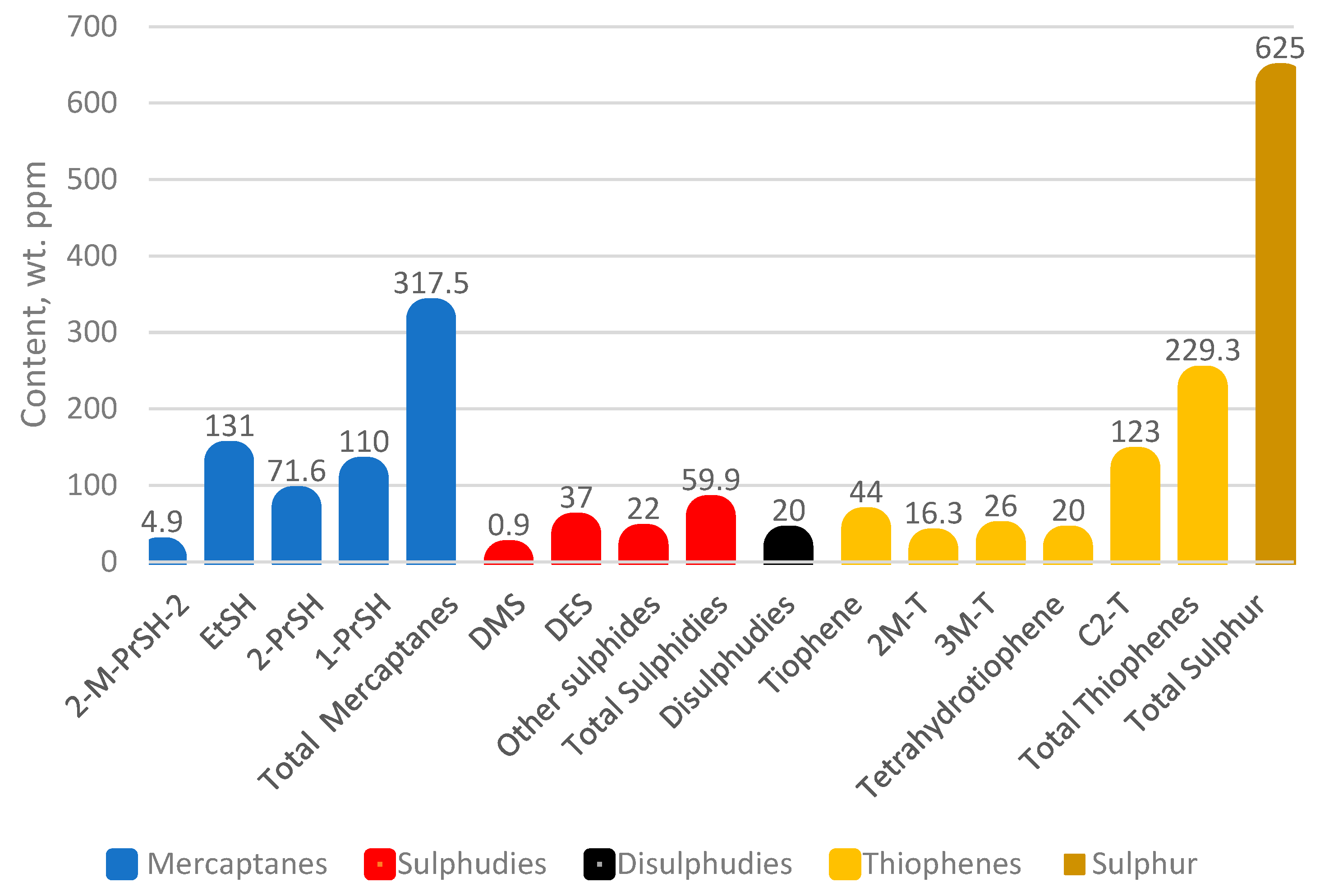
| Sulphur content, % | 0.068 |
| H2S content/calculated as sulphur/, ppm | absence |
| Total nitrogen, wt. ppm | 117 |
| ASTM D 86 distillation | |
| % vol. | °C |
| IBP | 36 |
| 5 | 54 |
| 10 | 65 |
| 20 | 77 |
| 30 | 85 |
| 40 | 94 |
| 50 | 101 |
| 60 | 109 |
| 70 | 116 |
| 80 | 124 |
| 90 | 133 |
| FBP | 143 |
| MAV (maleic anhydride value), g/mg | 1.37 |
| Research octane number | 59 |
| Motor octane number | 56 |
| Molecular weight, g/mol * | 109 |
| Catalyst at the LNB FCCU | Main Equilibrium Catalyst | ZSM-5 Containing Catalyst Additive |
|---|---|---|
| Total surface area, m2/g | 156 | 181 |
| Na2O, % | 0.19 | 0.16 |
| RE2O3, % | 3.15 | |
| Al2O3, % | 44.3 | 36.5 |
| APS, μm | 88 | 82 |
| ABD, g/cm3 | 0.85 | 0.72 |
| Unit cell size, Å | 24.34 | |
| Davison attrition index | 5 | 3 |
| Microactivity, % | 75.3 | |
| Coke factor | 0.89 | |
| Ni, ppm | 56 | |
| V, ppm | 188 |
| Stages of the Industrial Experiment | First Stage | Second Stage | |||||
|---|---|---|---|---|---|---|---|
| Case | 1 | 2 | 3 | 4 | 5 | 6 | 7 |
| Process indicators and yields | 16 August–19 August 2023—without H—Oil naphta | 23 August–24 August —with H—Oil naphtha | 3 September÷4 September 2023—with H—Oil naphtha | 13 September–14 September 2023: with H—Oil naphtha and ZSM5 | 4 October 2023 without H-Oil naphtha with ZSM5 | 20 November 2023 with H-Oil naphtha with ZSM5 | 1 December 2023 with H-Oil naphtha with ZSM5 |
| ZSM5 content in FCC inventory, % | 0 | 0 | 0 | 3 | 3 | 3 | 3 |
| FCC Feed Rate, t/h | 230 | 234.3 | 210.5 | 209.6 | 221.3 | 205.7 | 189.3 |
| H-Oil naphtha, t/h | 0 | 5.5 | 5.7 | 5.7 | 0 | 9.1 | 10.9 |
| H-Oil naphtha in FCC feed, wt, % | 0.0 | 2.3 | 2.7 | 2.7 | 0.0 | 4.4 | 5.7 |
| H-Oil VGO in FCC Feed, % | 21 | 19 | 17.5 | 16.7 | 17 | 28.3 | 19.6 |
| Riser outlet temperature, °C | 546 | 546.8 | 545 | 547 | 547 | 547 | 547 |
| Combined feed temperature, °C | 328 | 328.7 | 314.3 | 312.8 | 315 | 323 | 331.24 |
| Temperature of H- Oil naphtha coming in FCC riser, °C | 30.4 | 27.1 | 25.3 | 22.3 | 23.3 | ||
| Dense phase regenerator temperature, °C | 694 | 691.8 | 689.9 | 690.1 | 699 | 710 | 702 |
| Dilute phase regenerator temperature, °C | 708 | 706.5 | 705.9 | 709.6 | 714 | 720 | 716.3 |
| Product yields | |||||||
| Dry gas, wt,% | 5.5 | 5.5 | 5.5 | 5.7 | 5.3 | 7.0 | 7.0 |
| C3, wt,% | 7.4 | 7.7 | 7.6 | 8.3 | 8.1 | 6.9 | 7.1 |
| C4, wt,% | 12.5 | 12.6 | 12.6 | 13.4 | 13.5 | 11.7 | 12.3 |
| FCC gasoline, wt,% | 46.5 | 47.8 | 47.0 | 45.4 | 45.3 | 45.3 | 45.3 |
| LCO, wt,% | 9.3 | 9.1 | 8.9 | 8.4 | 8.2 | 8.3 | 8.3 |
| HCO, wt,% | 9.1 | 8.3 | 8.0 | 8.2 | 7.8 | 8.4 | 8.4 |
| Slurry, wt,% | 4.8 | 4.1 | 5.3 | 5.2 | 6.7 | 7.1 | 6.4 |
| Coke, wt,% | 4.9 | 4.9 | 5.1 | 5.3 | 5.1 | 5.3 | 5.2 |
| FCC feed conversion, wt, % | 76.8 | 78.0 | 77.2 | 77.6 | 77.3 | 75.1 | 75.5 |
| H-Oil naphtha conversion, wt,% | 50.2 | ||||||
| FCC gasoline MON | 82.2 | 82.2 | 82.3 | 82.3 | 82.3 | 82.2 | 82.2 |
| FCC gasoline RON | 94.2 | 93.8 | 93.8 | 94.3 | 94.4 | 94.3 | 94.2 |
| Prime G gasoline MON | 82.2 | 82.1 | 82.2 | 82.2 | 82.2 | 82.1 | 82 |
| Prime G gasoline RON | 93.7 | 93.3 | 93.5 | 93.8 | 93.6 | 93.6 | 93.2 |
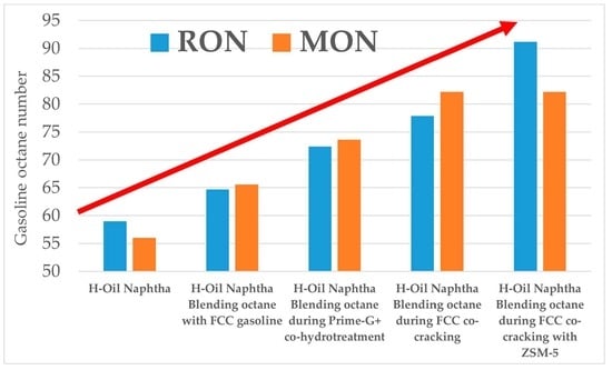
| H-Oil Naphtha Utilization Options | RON | MON |
|---|---|---|
| Stand alone | 59 | 56 |
| Blending with Prime-G+ FCC hydrotreated gasoline | 64.7 * | 65.6 * |
| Co-processing with FCC gasoline | 72.4 * | 73.6 * |
| Co-processing with VGO in FCC unit | 77.9 * | 82.2 * |
| H-Oil Naphtha Processed in FCCU, t/h | 0 | 5 | 6 | 0 | |||||
|---|---|---|---|---|---|---|---|---|---|
| Recipe, vol.% | Case 1 | Case 2 | Case 4 | Case 5 | |||||
| RON | MON | RON | MON | RON | MON | RON | MON | ||
| FCC gasoline | 51.5 | 94.2 | 82.2 | 93.8 | 82.2 | 94.3 | 82.3 | 94.3 | 82.3 |
| Reformate | 25 | 99.8 | 88.8 | 99.8 | 88.8 | 99.8 | 88.8 | 99.8 | 88.8 |
| Alkylate | 13 | 96.5 | 93.1 | 96.5 | 93.1 | 96.5 | 93.1 | 96.5 | 93.1 |
| MTBE | 6.5 | 111 | 97 | 111 | 97 | 111 | 97 | 111 | 97 |
| Naphtha | 4 | 64 | 62 | 64 | 62 | 64 | 62 | 64 | 62 |
| ZSM-5 | no | no | yes | yes | |||||
| RON of commodity gasoline | 96.8 | 96.8 | 97.8 | 97.9 | |||||
| MON of commodity gasoline | 85 | 85 | 85.6 | 85.8 | |||||
| FCC Gasoline | FCC Gasoline | Prime-G+ Hydrotreated FCC Gasoline | Prime-G+ Hydrotreated FCC Gasoline | |
|---|---|---|---|---|
| Gasoline blend composition | vol.% | |||
| FCC gasoline | 51.50 | 50.70 | 50.70 | 51.50 |
| Reformate | 25.00 | 24.61 | 24.61 | 25.00 |
| Alkylate | 13.00 | 12.80 | 12.80 | 13.00 |
| Naphtha | 4.00 | 5.50 | 5.50 | 4.00 |
| MTBE | 6.50 | 6.40 | 6.40 | 6.50 |
| Total | 100 | 100 | 100 | 100 |
| RON | 97.3 | 97.0 | 96.3 | 96.4 |
| MON | 85.6 | 85.4 | 85.2 | 85.3 |
Disclaimer/Publisher’s Note: The statements, opinions and data contained in all publications are solely those of the individual author(s) and contributor(s) and not of MDPI and/or the editor(s). MDPI and/or the editor(s) disclaim responsibility for any injury to people or property resulting from any ideas, methods, instructions or products referred to in the content. |
© 2023 by the authors. Licensee MDPI, Basel, Switzerland. This article is an open access article distributed under the terms and conditions of the Creative Commons Attribution (CC BY) license (https://creativecommons.org/licenses/by/4.0/).
Share and Cite
Stratiev, D.; Shishkova, I.; Ivanov, M.; Dinkov, R.; Toteva, V.; Angelova, D.; Kolev, I.; Tavlieva, M.; Yordanov, D. Alternative Options for Ebullated Bed Vacuum Residue Hydrocracker Naphtha Utilization. Processes 2023, 11, 3410. https://doi.org/10.3390/pr11123410
Stratiev D, Shishkova I, Ivanov M, Dinkov R, Toteva V, Angelova D, Kolev I, Tavlieva M, Yordanov D. Alternative Options for Ebullated Bed Vacuum Residue Hydrocracker Naphtha Utilization. Processes. 2023; 11(12):3410. https://doi.org/10.3390/pr11123410
Chicago/Turabian StyleStratiev, Dicho, Ivelina Shishkova, Mihail Ivanov, Rosen Dinkov, Vesislava Toteva, Daniela Angelova, Iliyan Kolev, Mariana Tavlieva, and Dobromir Yordanov. 2023. "Alternative Options for Ebullated Bed Vacuum Residue Hydrocracker Naphtha Utilization" Processes 11, no. 12: 3410. https://doi.org/10.3390/pr11123410
APA StyleStratiev, D., Shishkova, I., Ivanov, M., Dinkov, R., Toteva, V., Angelova, D., Kolev, I., Tavlieva, M., & Yordanov, D. (2023). Alternative Options for Ebullated Bed Vacuum Residue Hydrocracker Naphtha Utilization. Processes, 11(12), 3410. https://doi.org/10.3390/pr11123410