Article

Numerical Study and Hydrodynamic Calculation of the Feasibility of Retrofitting Tangentially Fired Boilers into Slag-Tap Boilers

1
Shenhua Group CFB Technology R&D Center, CFB Research and Development Department (R&D), Xi’an 710065, China
2
State Key Laboratory of Multiphase Flow in Power Engineering, School of Energy and Power Engineering, Xi’an Jiaotong University, Xi’an 710049, China
3
China Special Equipment Inspection and Research Institute, Beijing 100029, China
*
Author to whom correspondence should be addressed.
Processes 2023, 11(12), 3442; https://doi.org/10.3390/pr11123442
Submission received: 18 November 2023 / Revised: 9 December 2023 / Accepted: 13 December 2023 / Published: 16 December 2023

Abstract

:
Retrofitting a tangentially fired boiler into a slag-tap boiler offers a solution for fully burning high-alkali coal in power plant boilers. Numerical simulation and hydrodynamic calculation of such a retrofit scheme were performed in this study. The maximum temperature in the furnace after retrofitting is 2306.8 K, surpassing the pre-retrofit temperature of 2095.8 K. The average temperature in the combustion chamber of the slag-tap boiler is 2080.3 K, which ensures that the slag can be discharged in a molten state. When the coal consumption is halved relative to the working condition of the boiler maximum continuous rating (BMCR) in the slag-tap boiler, the maximum temperature in the combustion chamber decreases from 2306.8 to 2220.3 K. However, the temperature distribution remains relatively uniform, ensuring that the slag discharge is not disrupted. In both of the working conditions calculated in this study, the fluid flow rates in the water-cold wall are positively correlated with the wall heat fluxes. The maximum wall temperatures under the two working conditions are 653.9 and 590.6 K, respectively, both of which are well within the safe limits for the wall material. The results illustrate the feasibility of the retrofit scheme.

1. Introduction

High-alkali coal refers to coal with a high content of alkali metal oxides such as sodium and potassium [1]. Its volatile content and calorific value are high, whereas its hydrocarbon content is relatively low [2]. Distributed worldwide [3], high-alkali coal resources are abundant in China [4], particularly in northwest China [5]. It can be used in thermal power generation [3], chemical production [6], metallurgical industry [7], and other fields. Due to its high calorific value and low sulfur content, high-alkali coal is an ideal fuel choice [8]. However, a high alkali metal content reduces the melting temperature of ash particles [9]. Meanwhile, it promotes the release of gas-phase sodium, which solidifies easily on the wall of the boiler [10]. Therefore, burning high-alkali coal has a large tendency to form ash and slag in boilers, making equipment maintenance and cleaning more challenging. To utilize high-alkali coal resources more effectively, research and technological innovation are necessary.
Most technologies are aimed at fuel adjustment, such as co-firing [11,12], which is the most widely used method, adding additives [13], and extracting alkali metal [5]. Adjusting the boiler structure is another approach. The slag-tap boiler has been proven to be a feasible way to efficiently burn high-alkali coal. Compared with dry-bottom boilers, the temperature in the primary combustion zone of slag-tap boilers is high. In slag-tap boilers, the ash adhered to the wall forms a slag film in the molten state. Then, the ash in the flue gas is continuously captured, thereby reducing the volume of fly ash. Prokhorov et al. [14] used numerical methods to investigate the flow field of a slag-tap boiler. They judged the risk of slagging by the flow field but did not consider the effect of temperature. Wang et al. [15,16] studied the influence of the air ratio on NOx generation in slag-tap boilers using a numerical method. In their model, the slag film was simplified, and the focus was on heat and mass transfer in the furnace. Ni et al. [17] proved the hydrodynamic and slagging safety of liquid slag-tap boilers when burning high-alkali coal through experimental methods. However, the water-cold wall in their study was once-through; the natural circulation form of the water-cold wall was not discussed. Jing et al. [18] obtained the flue gas characteristics of slag-tap boilers that burn different fuels using the actual measurement method. Their results are of reference significance in numerical simulation.
Tangentially fired boilers comprise a large proportion of existing coal-fired power plants [19]. In a tangentially fired boiler, the high-temperature area is concentrated in the transverse middle of the furnace, whereas the temperature of the area close to the wall is low. Therefore, the fly ash easily slags on the wall. Meanwhile, the introduction of a staged combustion system places a large area of the furnace in a reducing atmosphere, which encourages high-temperature corrosion and leads to slag formation. Therefore, it is easy to slag on the heating surface of tangentially fired boilers [20,21,22,23], which limits their operation efficiency and increases maintenance demand. A promising method by which to achieve more complete burning of high-alkali coal while reducing the construction cost of new boilers is to retrofit some tangentially fired boilers into slag-tap boilers. However, few studies have analyzed the feasibility of such a scheme.
In previous studies [2,14,15,16,17,18], slag-tap boilers were generally newly built rather than retrofitted from old boilers. To save cost and simplify construction, the slag-tap boilers retain many original features after retrofitting. The size and structure of this kind of slag-tap boiler are very different from those of traditional slag-tap boilers. Therefore, it is necessary to evaluate the feasibility of the proposed scheme. In this study, the feasibility of retrofitting a tangentially fired boiler into a slag-tap boiler was studied. For a 300 MW boiler, the changes in the combustion characteristics of the boiler before and after the retrofit were compared using numerical simulation. Meanwhile, the combustion and hydrodynamic characteristics under variable boiler loads in the slag-tap boiler were analyzed.

2. Numerical Model Description

2.1. Retrofit Scheme

A 300 MW subcritical natural circulation boiler adopting tangential combustion was studied. It took the form of a vertical water-cold wall. The width of the furnace was 14.05 m. The depth was 13.97 m. The distance from the bottom of the ash hopper to the bottom of the platen superheater was 39.16 m. The structures of the furnace and burners are shown in Figure 1, and Table 1 details the boiler’s design parameters. The coal burned in the boiler was bituminous. Fuel property analysis is shown in Table 2.
Under the retrofit scheme, two combustion chambers measuring 5.7 m in depth and 13.93 m in height were positioned at the front and rear of the furnace. The water-cold walls in this area were curved inwards to reduce the furnace depth. Each combustion chamber was equipped with eight cyclone burners, while the original burners and air inlets were replaced. The boiler layout is depicted in Figure 2. Since the slag-tap boiler exhibits symmetry, only half of the model was constructed. The design coal of this boiler was Naomaohu coal. The fuel property analysis and melting temperature analysis of the ash are presented in Table 3 and Table 4.
In the case of slag-tap boilers, the water-cold wall has a complex structure, which often necessitates the adoption of a once-through water-cold wall to overcome the flow resistance. However, in this retrofit scheme, the natural circulation form of the water-cold wall in the original furnace, specifically in the cooling chamber after retrofitting, was preserved to minimize the retrofit costs. Meanwhile the once-through form was utilized in the newly constructed combustion chambers. More detailed information is provided below.

2.2. Numerical Model

The numerical simulation in this study was performed using Ansys Fluent software, version 2022 R1. In Fluent, the three conservation equations are solved numerically to determine the flow field of the fluid domain [24].
In this model, the energy equation was enabled to simulate heat transfer within the fluid and between the fluid and the walls. The realizable kε model was employed to capture the influence of turbulence [25]. For simulating the complex radiative heat transfer process in the boiler, the discrete ordinates model was used due to its wide application range and high calculation precision [26]. The species transport model was utilized to simulate interactions among the species in the fluid mixture or with other phases. In Fluent, pulverized coal in introduced into the fluid domain as particles. Therefore, it is necessary to activate the discrete phase model (DPM) to simulate the complex chemical reactions between the gas and the coal.
To optimize computation time, the equations related to flow and turbulence were solved first to obtain the converged flow field. After the flow field reached convergence, the remaining equations and the DPM were solved. Since the iterations involving DPM are time-consuming, it was set to iterate once every 30 iterations of the flow field.

2.3. Mesh Generation

Ansys Meshing software, version 2022 R1, was used for the meshing process. Taking the slag-tap boiler as an example, the division procedure is outlined. Various division strategies were implemented for different boiler sections. The burners and the combustion chamber experience intense chemical reactions, while the lower part of the cooling chamber has a dense structure of the slag collection tube bundles. Therefore, the tetrahedral grid was set in these areas to meet the structural requirements and ensure accuracy. In the upper part of the cooling chamber, where the shape is regular and the heat and mass transfer is minimal, the hexahedral dominant grid was utilized.
To prevent the interference of the grids number on the results, three meshes with different grid numbers were generated to simulate the BMCR working condition. The grid numbers used were 2.15 million, 3.10 million, and 4.89 million. The temperature results along the centerline of the combustion chamber are depicted in Figure 3. As the grid number increases from 3.10 million to 4.89 million, the root mean square error (RMSE) of the temperature results at each point is only 9.5 K. Hence, the mesh with a grid number of 3.10 million was chosen as the final mesh, as shown in Figure 4. The grid size of the tangentially fired boiler was determined with reference to that of the cooling chamber. The resulting grid number for the tangentially fired boiler is 0.97 million, as illustrated in Figure 5.

2.4. Boundary Conditions

In this study, the boundary conditions of the air inlets were set as mass flow inlets. The mass flow rate for each inlet was determined based on the actual air mass flow distribution. The outlet boundary condition was set as the outflow. All walls of the boiler were defined as isothermal walls, while the walls of the cyclone burners were defined as insulated walls. The wall temperature of the boiler was set to different values in different regions. Specifically, the temperature in each region was set as the average temperature of the fluid at the inlet and outlet of the water-cold wall in that region, which was obtained through thermal calculations [20,27].

2.5. Simulated Working Conditions

To assess the changes in the heat and mass transfer in the boiler before and after the retrofit, as well as to evaluate the combustion stability and the hydrodynamic characteristics of the slag-tap boiler under varying load, four working conditions were designed, as shown in Table 5. Specifically, working conditions 1 and 2 represent the BMCR working conditions of the boiler before and after the retrofit, respectively, and working conditions 3 and 4 simulate the operation of the slag-tap boiler at 75% and 50% of the BMCR coal consumption rates, respectively.

3. Hydrodynamic Calculation Methods

3.1. Calculation Principle

The hydrodynamic calculation of this study is conducted using the nodal voltage method [28]. This method considers the steam–water system of a boiler as an interconnected network of tube sections, headers, drums, and other components. The hydrodynamic characteristics of each component are determined iteratively by formulating and solving equations specific to those components. The fundamental equations utilized in this method are the mass conservation equation and the flow rate–pressure drop relation equation.
Within this framework, a particular component can receive fluid from m components at the upper level and flow out to n components at the lower level. Additionally, it may also receive or discharge a portion of the fluid from or to the external environment, as shown in Figure 6. The mass conservation equation is presented below:
i = 1 m G in ,   i = j = 1 n G out ,   j + G S ,
where Gin,i represents the flow from the component i at the upper level (kg s−1), Gout,i represents the flow into the component i at the lower level (kg s−1), and Gs represents the mass source term (kg s−1), that is, the flow exchanged between the component and the external environment. When the flow is leaving the component, the value of Gs is positive; otherwise, it is negative.
The formula for calculating the pressure drop in a component can be written as follows:
Δ p = R G 2 + ρ ¯ g h ,
where Δp is the pressure drop in the component (Pa), R is the drag coefficient (kg−1 m−1), ρ ¯ represents the average fluid density in the component (kg m−3), g represents the acceleration of gravity (m s−2), and h represents the height from the inlet of the component to the outlet (m).
The hydrodynamic calculation involves an iterative process. Equation (2) can be transformed to derive the flow rate–pressure drop relation equation:
G = Δ p ρ ¯ g h R G 0 ,
where G0 refers to the flow result in the previous iteration of the calculated component (kg s−1).
The steam–water system exhibits intricate interconnections among its various components, resembling the interconnected nature of circuits. These connections can be classified into series and parallel relationships, akin to electrical circuits. In a series connection, the flow rates of the connected parts are equal, while in a parallel connection, the pressure drops remain equal.
To determine the hydrodynamic characteristics, initial assumptions are made for the fluid flow, pressure drop, and enthalpy of each component. The coefficients in the equations are then updated using the obtained results. Subsequently, the new pressure drop and flow rate are calculated in successive steps of iteration until the computed error falls within acceptable limits.
The calculation of enthalpy is an integral part of this process and is coupled with the calculation of wall temperature. The calculation method is as follows:
t ave = t w + μ ( r ) ¯ β q o 10 3 [ 1 α 2 + δ λ ( β + 1 ) ]   ,
t o = t w + μ ( r o ) β q o 10 3 [ 1 α 2 + 2 δ λ ( β + 1 ) ]   ,
where tave is the tube wall average temperature (K), tw is the fluid temperature (K), μ(r) is the heat diversion coefficient at the radius r, β is the ratio of the outer diameter of the tube to the inner diameter, qo is the heat flux accepted by the tube section (W m−2), α2 is the convective heat transfer coefficient (W m−2 K−1), δ is the wall thickness (mm), and λ is the thermal conductivity of the metal (W m−1 K−1).

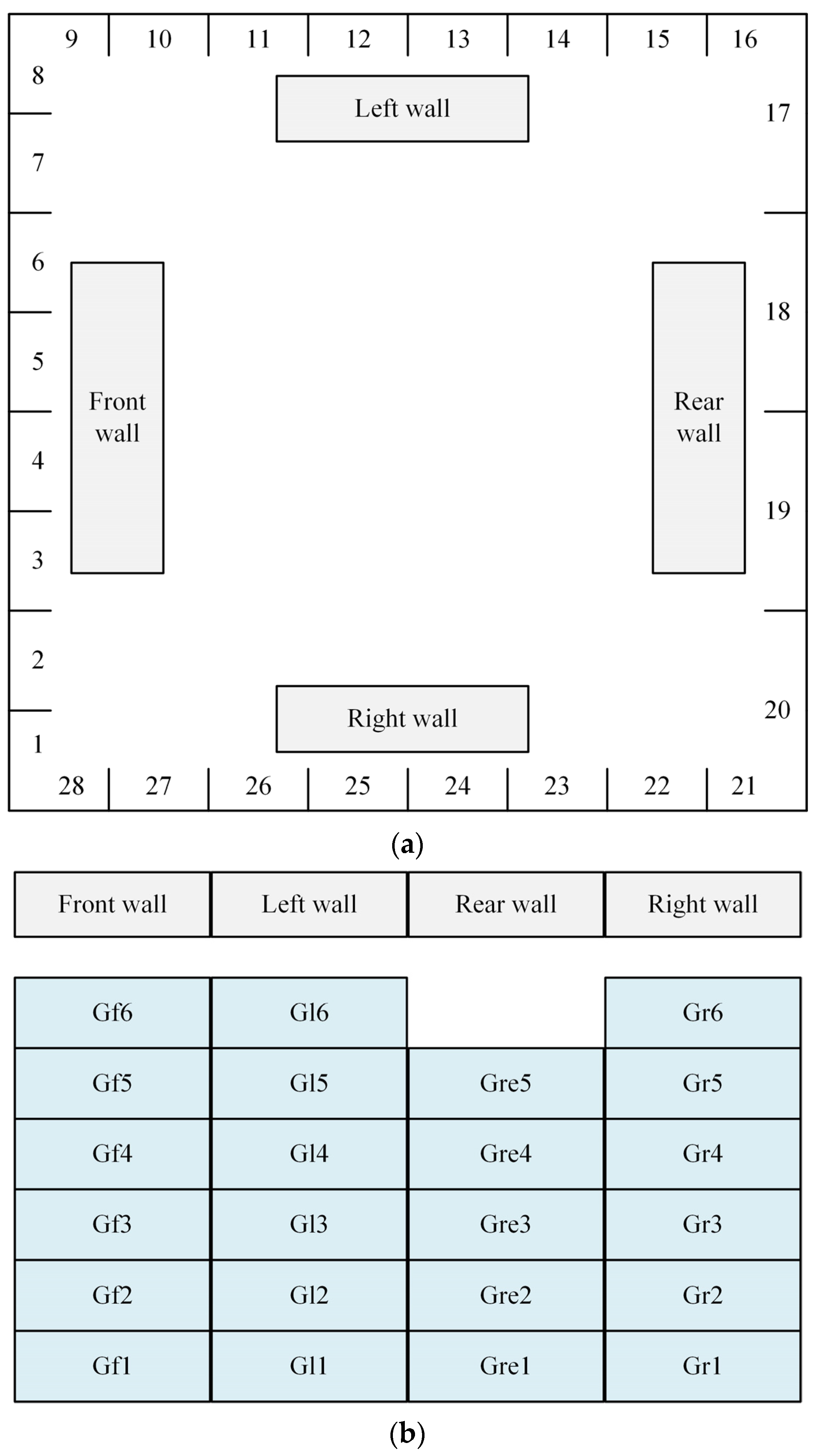
3.2. Division of Steam–Water System

The hydrodynamic calculation of the slag-tap boiler was carried out. Specifically, the calculation focused on a natural circulation drum boiler. The water-cold wall from the combustion chamber to the inlet header for the cooling-chamber water-cold wall was designed as a series once-through structure. The water-cold wall of the cooling chamber was designed as a natural circulation structure. The water-cold wall in this area comprised a combination of spiral rising tube bundles and vertical rising tube bundles. Figure 7 illustrates the layout of the boiler’s heating surface, representing the steam–water system as a flow diagram composed of tube panels and headers.
To calculate accurately, a detailed segmentation of the water-cooled wall is essential. In terms of width, the outlet of the cooling chamber’s water-cold wall was divided into 28 sections. The left, front, and right walls were each divided into eight zones. Due to the presence of suspension pipes, the vertical portion of the rear wall was relatively short and was divided into only one zones. Figure 8a illustrates the numbering system, which begins from the right side of the front wall and increases clockwise. In the height dimension, the water-cold wall of the cooling chamber was divided into six zones, while the rear wall was divided into five zones due to the presence of suspension pipes. The corresponding serial numbers are shown in Figure 8b.

4. Results and Discussion

4.1. Model Validation

Thermal calculation is a process used to determine the thermal performance of the boiler. One of the functions of thermal calculation is to determine the flue gas temperature before and after flowing through each heating surface [29,30]. Since the considered boiler in this study is a retrofit scheme without actual operation data for reference, the validity of the numerical model was verified by comparing it with the results of the thermal calculation.
The thermal calculation of working condition 2 was performed. The results were compared with the numerical results. The maximum combustion temperature obtained from the numerical simulation is 2306.8 K, which is 34.6 K higher than the result from thermal calculation. At the platen bottom, the numerical and thermal results are 1520.6 and 1482.2 K, respectively. By considering the comparison results in previous literature [29,31], it is evident that the comparison results in this study are sufficient to demonstrate the accuracy of the numerical model.

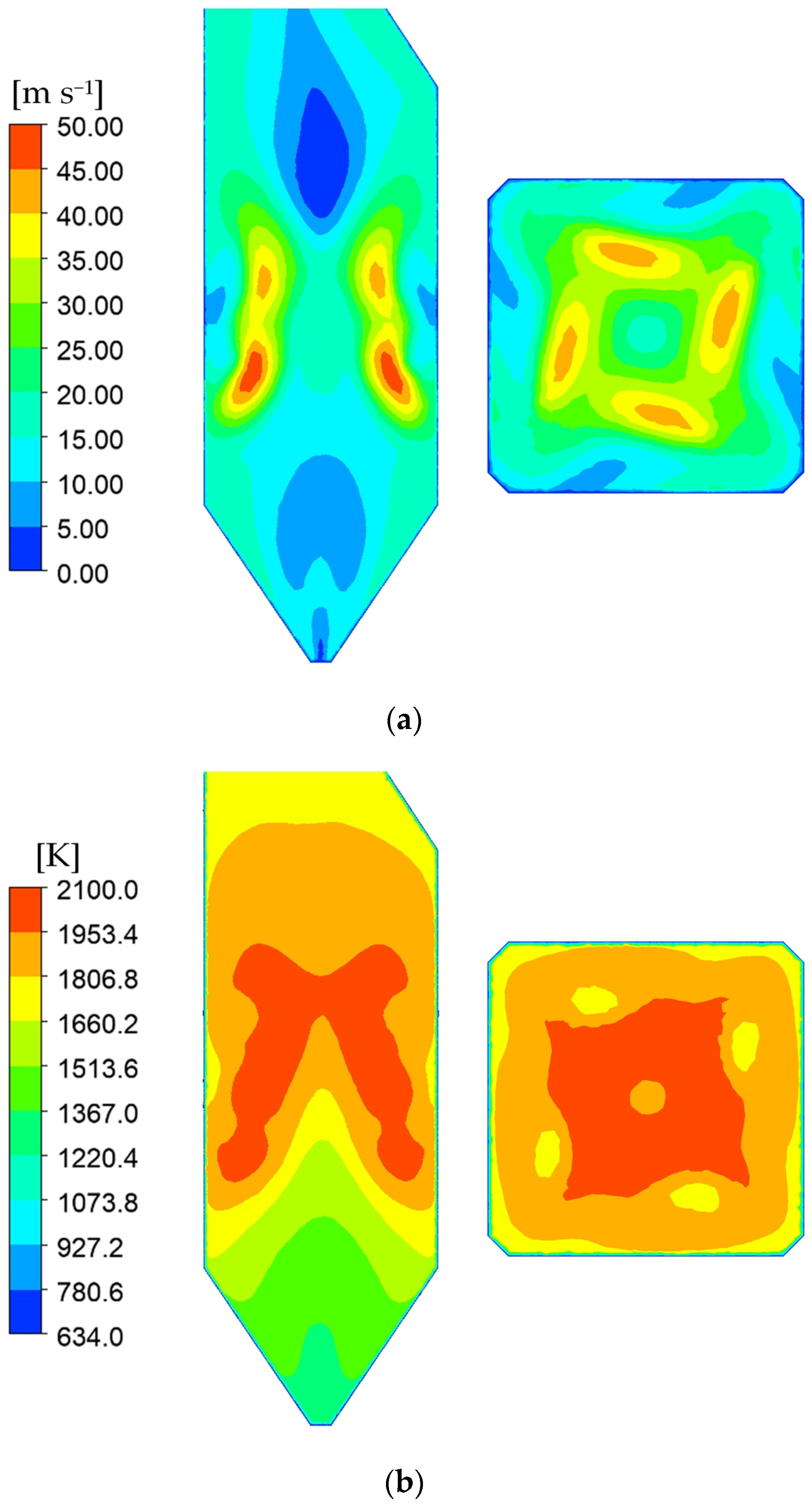
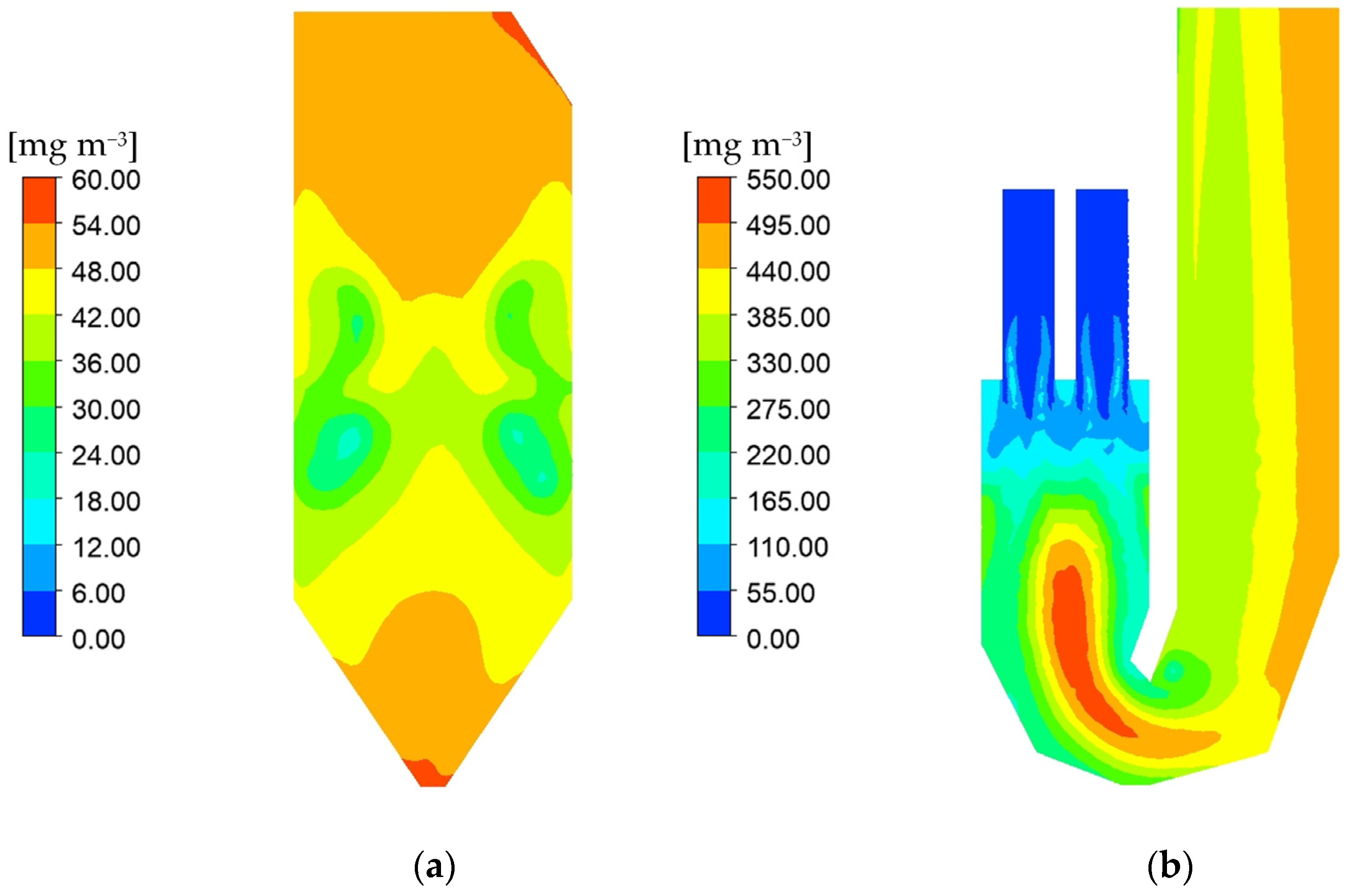
4.2. Comparison before and after Retrofit

Figure 9 illustrates the flow and temperature fields in the tangentially fired boiler under BMCR condition. The air flows approach from four directions, creating a tangential circulation pattern in the transverse central region of the furnace. This circulation enhances disturbance and improves the filling degree of flue gas in the furnace [32]. The combustion heat release primarily occurs in the transverse central area of the furnace, where the burners are positioned. Consequently, the temperature in the middle and upper parts of the furnace is higher. The maximum temperature in the furnace is approximately 2095.8 K.
It is obvious that the utilization of high-alkali coal in conventional tangentially fired boilers would lead to significant problem of slagging. If the flame skews or the tangential circulation is excessive, resulting in tangential erosion of the water-cold wall, the molten particles easily adhere to the wall and then form slag [33]. Moreover, ash particles continue to traverse through the superheater, slag screen, and other densely arranged heated surfaces, which would also result in serious slagging [34].
Figure 10 shows the flow and temperature fields in the slag-tap boiler under BMCR condition. Combustion predominantly occurs in the cyclone burners in this type of boiler. The secondary air causes the pulverized coal to swirl vigorously in the burners, which promotes efficient fuel burning. Each combustion chamber has a volume of 994 m3, while the average flue gas velocity here reaches 22.96 m/s. Therefore, high-temperature flue gas fills the entire combustion chamber quickly. This is consistent with the results in the literature [15]. Given the relatively concentrated combustion area in the slag-tap boiler, the maximum combustion temperature is high, reaching 2306.8 K. Different from the tangentially fired boiler, the flue gas temperature remains high near the water-cold wall in the combustion chamber of the slag-tap boiler. In addition, the temperature near the ash hopper is also high. This allows the ash particles adhering to the wall to keep flowing down and exit the boiler in a molten state [35].
The streamline of pulverized coal particles entering the cyclone burners is shown in Figure 11. It reveals that pulverized coal enters the cyclone burners via the primary air inlet. Under the effect of tangential secondary air, the pulverized coal particles swirl along the cyclone burners wall, prolonging their residence time in the cyclone burners [15]. When the pulverized coal proceeds into the combustion chamber, it intermingles with particles from other cyclone burners, ensuring thorough filling of the combustion chamber with flue gas.
The temperature distribution patterns in various cross sections of the cyclone burners exhibit similarity. Along the radial direction, the temperature increases initially and then decreases, as shown in Figure 12a. This can be attributed to the movement of pulverized coal particles along the burners wall due to the swirling flows. Therefore, the temperature in the center of the burners is lower [36]. Additionally, Figure 12a indicates that the average temperature of different sections gradually increases from the top to the bottom of the burners. Figure 12b shows the temperature field in the combustion chamber. Since the pulverized coal particles are mostly burned out in this region, and the flue gas is well-mixed and dispersed, the temperature field is distributed relatively evenly, ensuring the presence of high flue gas temperatures near the walls of the combustion chamber.
The high emission of NOx in slag-tap boilers is a significant issue that requires attention. In coal-fired boilers, the focus is primarily on thermal NOx and fuel NOx [37], which can be calculated by activating the corresponding models in Fluent. Figure 13 presents a comparison of NOx concentration distribution between the tangentially fired boiler and the slag-tap boiler. The NOx emission from the slag-tap boiler is considerably higher than that from the tangentially fired boiler. The average outlet NOx concentration of the slag-tap boiler is 380.6 mg m−3, while for the tangentially fired boiler, it is only 53.1 mg m−3. This stark difference arises due to the higher combustion temperature and larger high-temperature region in the slag-tap boiler. The elevated temperature promotes the generation of thermal NOx [38]. Obviously, it is necessary to consider the optimization of the de–NOx system when implementing the retrofit scheme in practice.

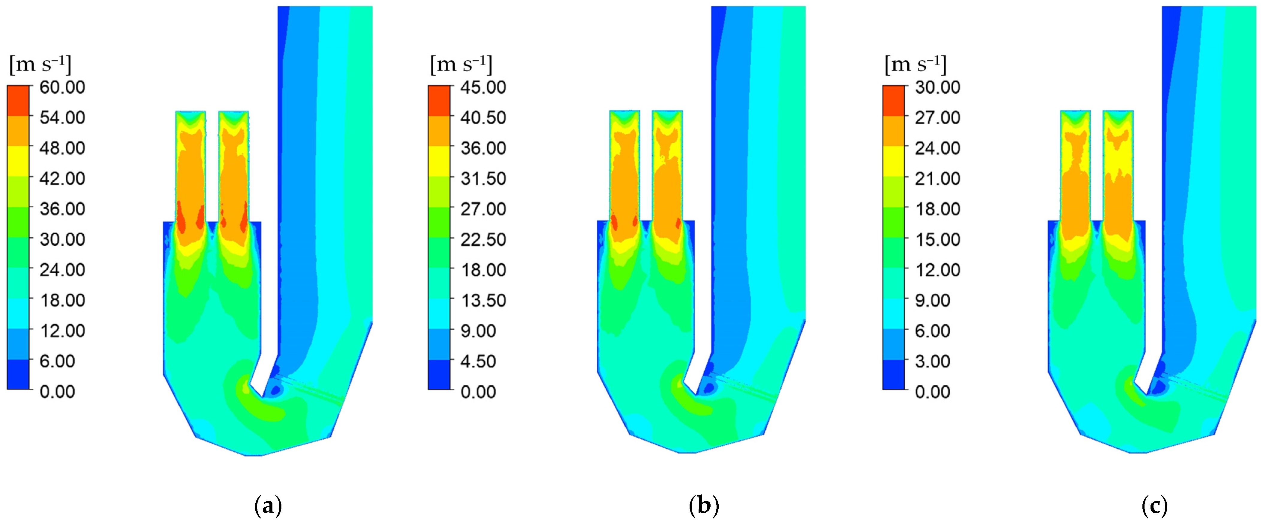
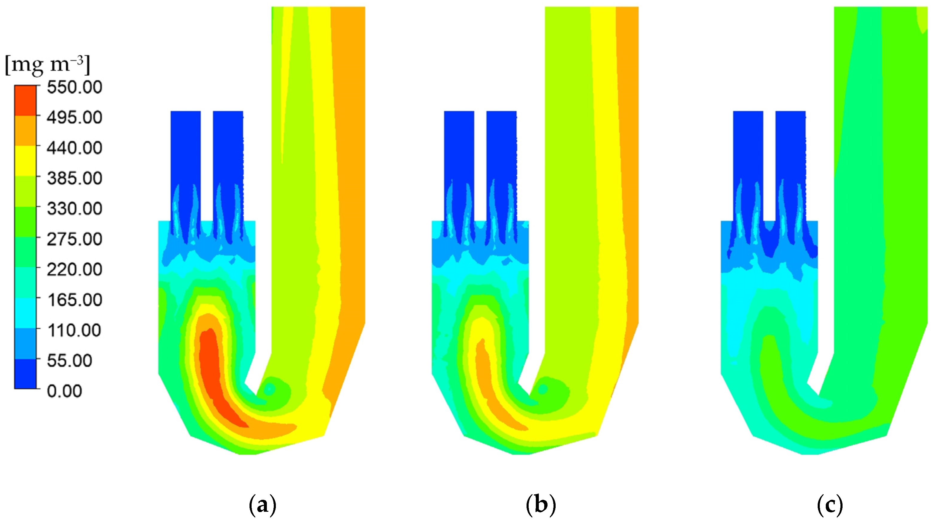
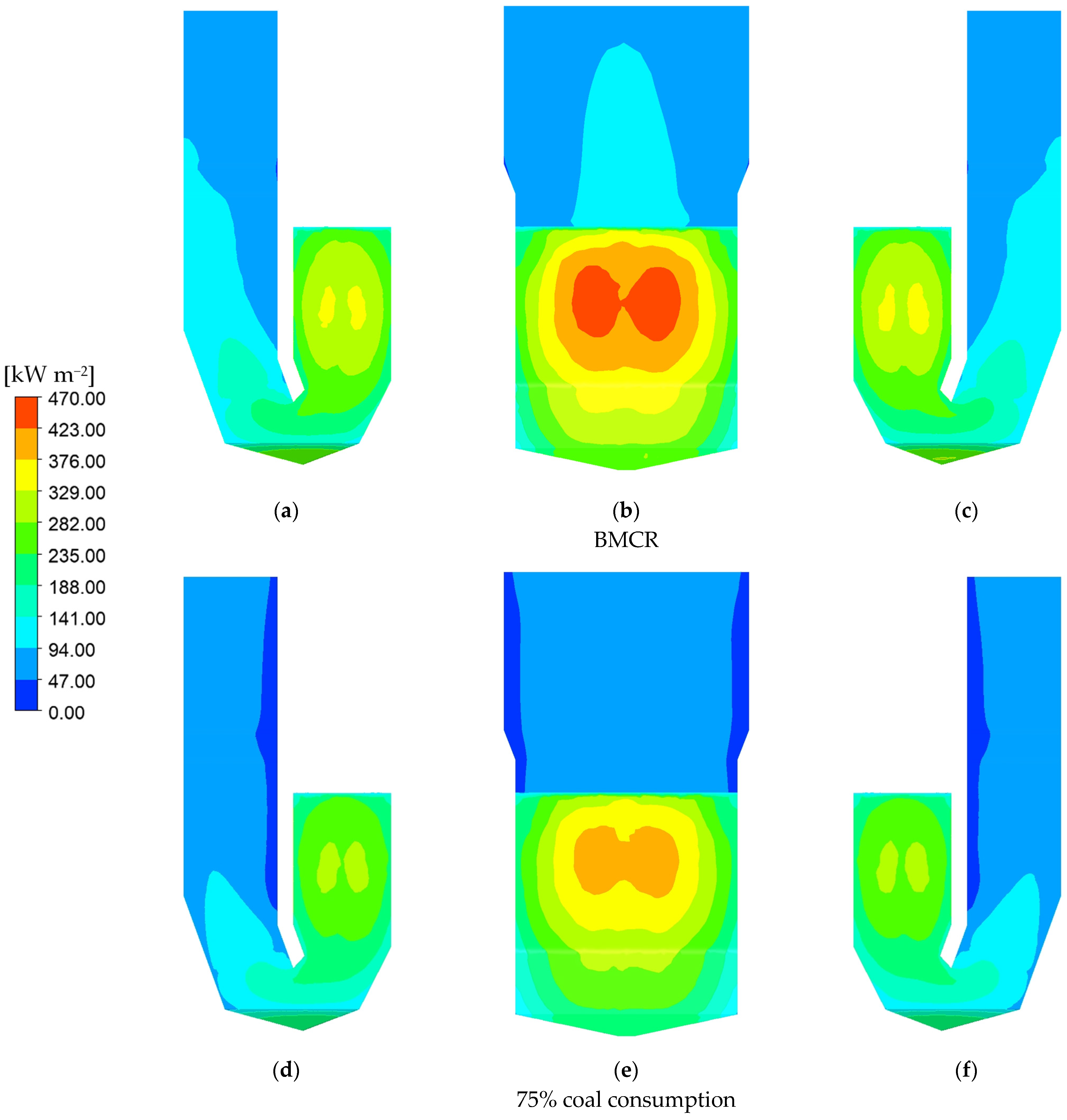
4.3. Combustion Characteristic of the Slag-Tap Boiler under Varying Boiler Loads

Figure 14 shows the flow field in the slag-tap boiler under three working conditions: with 100%, 75% and 50% coal consumption relative to BMCR condition. When the coal consumption decreases proportionally, the contour of the flow field remains largely unchanged, but the magnitude of the flow decreases proportionally, which indicates that the combustion chamber can still maintain a high filling degree of flue gas under lower boiler loads.
Figure 15 illustrates the temperature field under the same working conditions mentioned above. When the coal consumption is decreased in proportion, the overall temperature in the furnace shows a significant decrease, particularly evident in the combustion chamber. When the coal consumption decreases from 100% to 50% of BMCR, the maximum temperature in the combustion chamber drops from 2306.8 to 2220.3 K, while the average temperature in the combustion chamber decreases from 2080.3 to 1909.1 K. Meanwhile, the temperature at the platen bottom drops from 1520.6 to 1264.0 K. Despite the lower load, the well-organized flow field ensures a relatively uniform temperature distribution in the combustion chamber, allowing ash particles to remain in a molten state on the wall surface. With the decrease in coal consumption, NOx concentration in the boiler continuously decreases, as shown in Figure 16. When the coal consumption is at 50% of BMCR, the outlet NOx concentration significantly drops to 285.1 mg/m−3. However, it remains much higher than that of the tangentially fired boiler.
Figure 17 displays the distribution of wall heat flux in the furnace under the above working conditions. Due to the high flue gas temperature in the combustion chamber, the wall heat flux in this region is the highest. Under BMCR condition, the heat flux at the water-cold wall of the combustion chamber accounts for approximately 50.6% of the total heat flux. With the drop of boiler load, the heat flux correspondingly decreases. The primary area of decline is the water-cold wall of the combustion chamber, especially the front and rear walls, while the heat flux of the cooling chamber decreases slightly. The flame temperature in the center of the furnace tends to be the highest. Therefore, on the same wall, the heat flux is always highest in the middle region.

4.4. Hydrodynamic Characteristic of the Slag-Tap Boiler

When performing the hydrodynamic calculation, it is necessary to determine the heat flux of each tube panel in the steam–water system [39]. In this study, the numerical and thermal calculation results were comprehensively taken into account to assign the heat absorption value of each tube panel.
The hydrodynamic calculations were performed for the working conditions with 100% and 75% coal consumption relative to the BMCR condition. In a natural circulation boiler, the normal water circulation characteristic is that when the thermal conditions of the riser tube change, the circulation flow rate can always maintain a high value. Additionally, as the heat flux intensifies, there is a corresponding increase in flow rate [40,41]. Since the heat flux is highest in the middle of the wall, the flow distribution results on the four walls of these two working conditions also exhibit a similar trend, as shown in Figure 18.
The results of wall temperature distribution under the two calculated conditions are presented in Table 6 and Table 7. Since fin tubes are utilized in the water-cold wall, it is possible for the highest wall temperature to occur either at the front point or at the fin center. This study considers both possibilities. Under BMCR conditions, the maximum wall temperature reaches 653.87 K, specifically located on the lower rear wall. Under the condition of 75% coal consumption relative to BMCR condition, the maximum wall temperature is 590.57 K, positioned on the upper rear wall. The wall temperature results are all within the safe operating temperature range of the pressure components made of the 20 G material (about 723 K).

5. Conclusions

The numerical simulation and hydrodynamic calculation of retrofitting a 300 MW tangentially fired boiler into a slag-tap boiler are carried out. The temperature and flow fields in the furnace before and after the retrofit were compared. The combustion and hydrodynamic characteristics of the furnace after the retrofit under variable boiler loads were studied. The conclusions can be drawn as follows:
  • The maximum temperature in the slag-tap boiler is higher than that in the tangentially fired boiler, with values of 2095.8 and 2306.8 K, respectively. Moreover, the filling degree of high temperature flue gas is higher in the combustion chamber of the slag-tap boiler. The average temperature in the combustion chamber is 2080.3 K, ensuring that the slag can be discharged in a molten state.
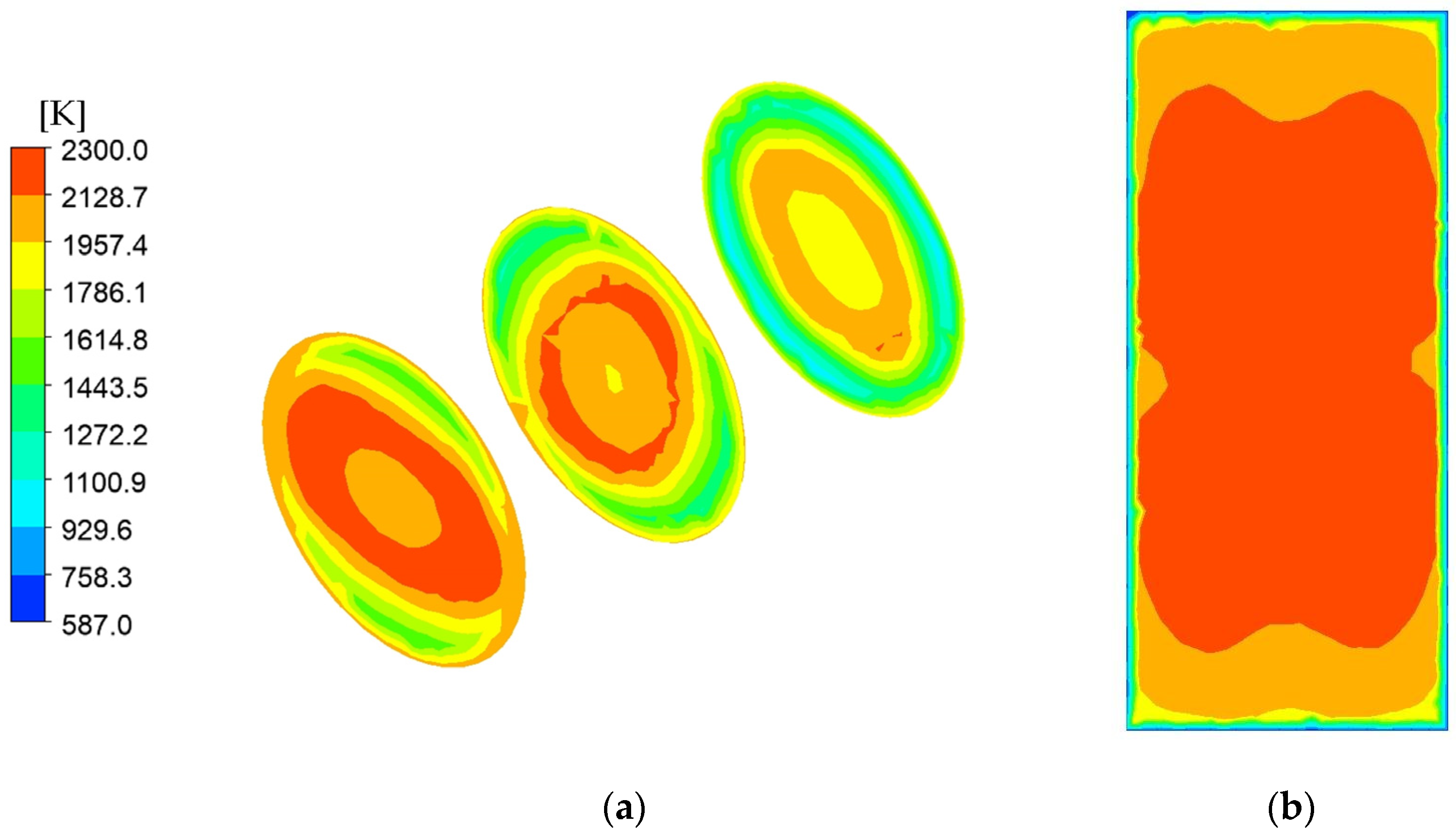
  • When the boiler load is decreased, the temperature level in the furnace drops obviously. When the coal consumption is halved from the BMCR condition, the maximum temperature in the furnace decreases from 2306.8 to 2220.3 K. However, the temperature distribution in the combustion chamber remains relatively uniform, which would not affect the discharge of slag.
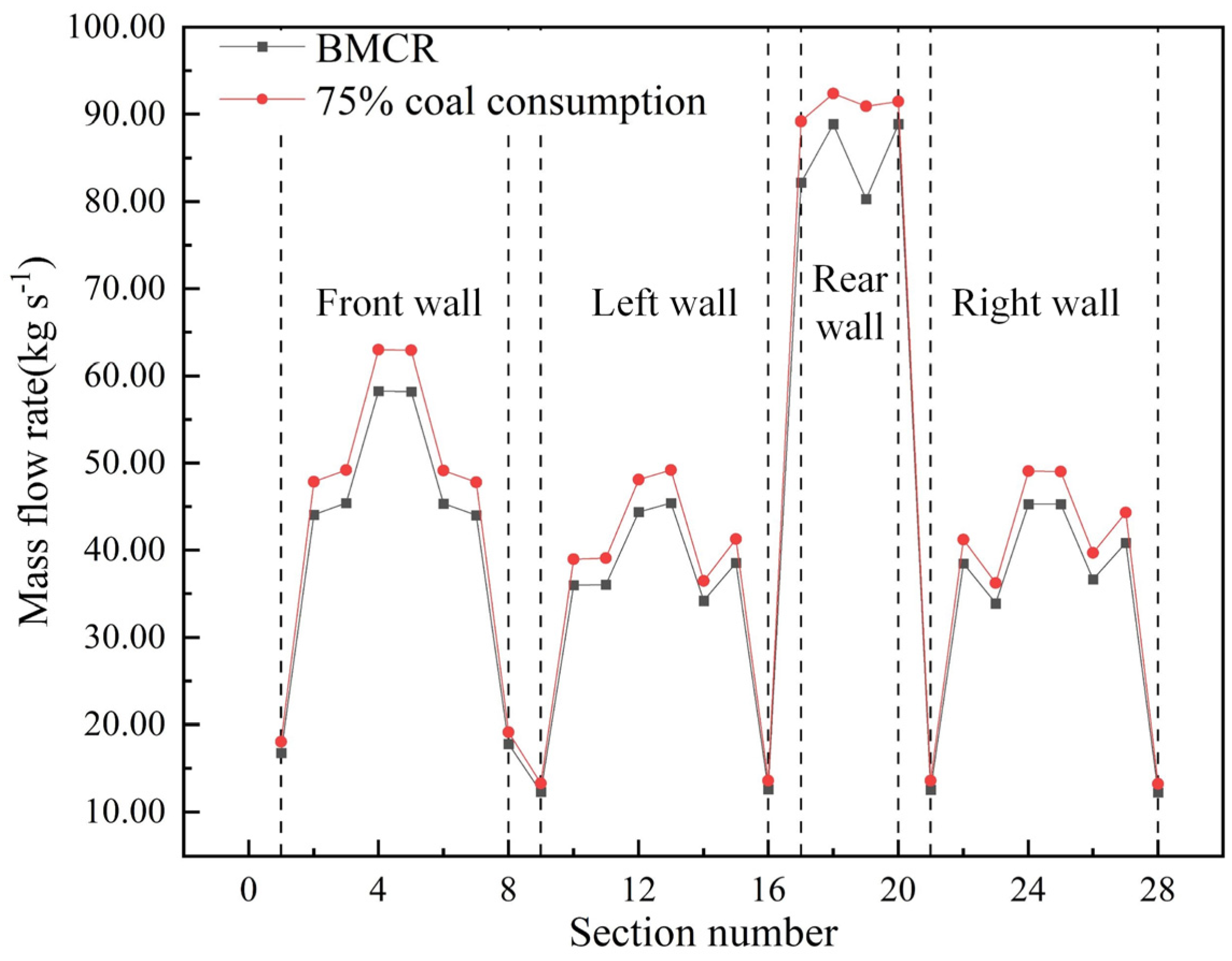
  • The slag-tap boiler exhibits reliable hydrodynamic characteristics. Under both calculated conditions, the fluid flow rate in the water-cold wall is positively correlated with the heat flux. The maximum wall temperatures under the two working conditions are 653.9 and 590.6 K, respectively, both within the safe range of the tube wall material.
  • Based on the results obtained in this study, the proposed retrofit scheme demonstrates robust performance in terms of slagging and hydrodynamic safety. This retrofit approach provides a practical solution for effectively burning high-alkali coal by retrofitting tangentially fired boilers into slag-tap boilers.

Author Contributions

Conceptualization, Q.G. and J.Y.; methodology, Q.G. and J.D.; validation, J.Y. and Y.Z.; formal analysis, Y.D.; investigation, Y.D. and D.C.; resources, D.C.; data curation, J.Y.; writing—original draft preparation, Q.G.; writing—review and editing, J.Y. and Y.Z.; supervision, J.D.; project administration, D.C.; funding acquisition, Q.G., Y.Z. and J.D. All authors have read and agreed to the published version of the manuscript.

Funding

This research was funded by the Shenhua Shendong Power Co., Ltd. 2023 Science and Technology Innovation Project, grant number GSKJ-23-46. The funders had no role in the design of the study; in the collection, analyses, or interpretation of data; in the writing of the manuscript; or in the decision to publish the results.

Data Availability Statement

The data presented in this study are available on request from the corresponding author. The data are not publicly available due to privacy.

Conflicts of Interest

Authors Qianxin Guo, Yonggang Zhao, and Jiajun Du are employees of the company Shenhua Group CFB Technology R&D Center. Author Yaodong Da is an employee of the company China Special Equipment Inspection and Research Institute. The remaining authors declare that the research was conducted in the absence of any commercial or financial relationships that could be construed as a potential conflict of interest.

References

  1. Sun, P.; Wang, C.; Zhang, M.; Cui, L.; Dong, Y. Ash problems and prevention measures in power plants burning high alkali fuel: Brief review and future perspectives. Sci. Total Environ. 2023, 901, 165985. [Google Scholar] [CrossRef] [PubMed]
  2. Ni, Y.; Hu, S.; Zhang, Y.; Zhang, M.; Li, H.; Zhou, H. Research on the effects of the fly ash reburning on element migration and ash deposition characteristics of high-alkali coal in a full-scale slag-tapping boiler. Fuel 2023, 335, 126952. [Google Scholar] [CrossRef]
  3. Tang, C.; Pan, W.; Zhang, J.; Wang, W.; Sun, X. A comprehensive review on efficient utilization methods of high-alkali coals combustion in boilers. Fuel 2022, 316, 123269. [Google Scholar] [CrossRef]
  4. Zhang, T.; Li, Z.; Hu, F.; Huang, X.; Liu, Z. Correlation of sodium releasing and mineral transformation characteristics with ash composition of typical high-alkali coals. Fuel Process. Technol. 2021, 224, 107035. [Google Scholar] [CrossRef]
  5. Guo, J.; Zhang, M.; Yan, G.; Zhang, Z.; Zhao, P.; Guo, M.; Zhang, B. Removal of AAEMs from high alkali coal under supercritical CO2 fluid-citric acid extraction system. Energy Sources Part A Recovery Util. Environ. Eff. 2023, 45, 5836–5847. [Google Scholar]
  6. Wei, L.; Fan, Y.; Fang, F.; Guo, L.; Chen, Y.; Yang, T. Effect of sodium and mineral types on distribution of tar and BTEXN under high alkali coal fast pyrolysis. CIESC J. 2021, 72, 1702–1711. [Google Scholar]
  7. Jayasekara, A.S.; Brooks, B.; Steel, K.; Koshy, P.; Hockings, K.; Tahmasebi, A. Microalgae blending for sustainable metallurgical coke production—Impacts on coking behaviour and coke quality. Fuel 2023, 344, 128130. [Google Scholar] [CrossRef]
  8. Zhao, P.; Huang, N.; Li, J.; Cui, X. Fate of sodium and chlorine during the co-hydrothermal carbonization of high-alkali coal and polyvinyl chloride. Fuel Process. Technol. 2020, 199, 106277. [Google Scholar] [CrossRef]
  9. Vassilev, S.; Kitano, K.; Takeda, S.; Tsurue, T. Influence of mineral and chemical-composition of coal ashes on their fusibility. Fuel Process. Technol. 1995, 45, 27–51. [Google Scholar] [CrossRef]
  10. Guo, Y.; Bai, X.; Zhang, X.; Gao, G.; Wang, G.; Yao, W. Study on techniques for slagging prevention and ash deposition control in existing boilers burning high-alkali coal. Therm. Power Gener. 2022, 51, 131–140. [Google Scholar]
  11. Liu, Y.; Cheng, L.; Ji, J.; Zhang, W. Ash deposition behavior in co-combusting high-alkali coal and bituminous coal in a circulating fluidized bed. Appl. Therm. Eng. 2019, 149, 520–527. [Google Scholar] [CrossRef]
  12. Wang, Y.; Bai, Y.; Zou, L.; Liu, Y.; Li, F.; Zhao, Q. Co-combustion characteristics and ash melting behavior of sludge/high-alkali coal blends. Combust. Sci. Technol. 2024, 196, 177–194. [Google Scholar] [CrossRef]
  13. Hariana; Prismantoko, A.; Prabowo; Hilmawan, E.; Darmawan, A.; Aziz, M. Effectiveness of different additives on slagging and fouling tendencies of blended coal. J. Energy Inst. 2023, 107, 101192. [Google Scholar] [CrossRef]
  14. Prokhorov, V.; Kirichkov, V.; Chernov, S. Physical and mathematical modeling of solid fuel combustion in the application of direct-flow burners. J. Phys. Conf. Ser. 2019, 1261, 012028. [Google Scholar] [CrossRef]
  15. Wang, W.; Sun, Y.; Huang, Z.; Liao, Y.; Fang, F. Numerical simulation of NOx emission characteristics of a cyclone boiler with slag-tap furnace. ACS Omega 2020, 5, 29978–29987. [Google Scholar] [CrossRef] [PubMed]
  16. Wang, W.; Huang, Z.; Fang, F.; Liao, Y. Effect of primary air blade inclination angle on combustion and NOx emission of a cyclone boiler with slag-tap furnace. J. Chin. Soc. Power Eng. 2021, 41, 8–13. [Google Scholar] [CrossRef]
  17. Ni, Y.; Hu, S.; Meng, H.; Wang, J.; Li, H.; Zhou, H.; Ma, X.; Zhou, H. Experimental research on fully burning high-alkali coal in a 300 MW boiler with slag-tap furnace. Asia-Pac. J. Chem. Eng. 2022, 17, e2807. [Google Scholar] [CrossRef]
  18. Jing, X.; Pu, Y.; Li, Z.; Tang, Q.; Yao, B.; Fu, P.; Lou, C.; Lim, M. Experimental investigation of gaseous sodium release in slag-tapping coal-fired furnaces by spontaneous emission spectroscopy. Energies 2022, 15, 4165. [Google Scholar] [CrossRef]
  19. Zhou, C.; Zhou, H.; Xing, Y.; Zhang, J.; Zhou, M. Effect of additives on flow characteristics and sodium capture efficiency of high alkali coal ash slag. J. Zhejiang Univ.-Sc. A 2020, 54, 623–630. [Google Scholar]
  20. Liu, H.; Yu, P.; Xue, J.; Deng, L.; Che, D. Research and application of double-reheat boiler in china. Processes 2021, 9, 2197. [Google Scholar] [CrossRef]
  21. Zhu, M.; Lu, H.; Zhao, W.; Huang, S.; Chang, X.; Dong, L.; Kong, D.; Jing, X. A numerical study of ash deposition characteristics in a 660mw supercritical tangential boiler. Adv. Theor. Simul. 2023, 6, 2300133. [Google Scholar] [CrossRef]
  22. Zhong, Y.; Wang, X.; Xu, G.; Ning, X.; Zhou, L.; Tang, W.; Wang, M.; Wang, T.; Xu, J.; Jiang, L.; et al. Investigation on slagging and high-temperature corrosion prevention and control of a 1000 MW ultra supercritical double tangentially fired boiler. Energy 2023, 275, 127455. [Google Scholar] [CrossRef]
  23. Liao, X.; Zhang, Q.; Yang, W.; Qiu, Z.; Guo, R.; Liu, J.; Li, F.; Li, Y. The role of pulverized coal drying temperature in fly ash carbon content and slagging of a tangentially coal-fired boiler. Fuel 2019, 257, 115951. [Google Scholar] [CrossRef]
  24. Pei, J.; Zhang, Z.; You, C. Optimizing the combustion of low-quality coal by the wall wind auxiliary combustion method in a tangentially fired utility boiler. Combust. Sci. Technol. 2019, 191, 570–589. [Google Scholar] [CrossRef]
  25. Lamioni, R.; Bronzoni, C.; Folli, M.; Tognotti, L.; Galletti, C. Impact of H2-enriched natural gas on pollutant emissions from domestic condensing boilers: Numerical simulations of the combustion chamber. Int. J. Hydrogen Energy 2023, 48, 19686–19699. [Google Scholar] [CrossRef]
  26. Nakamura, H.; Zhang, J.; Hirose, K.; Shimoyama, K.; Ito, T.; Kanaumi, T. Generating simplified ammonia reaction model using genetic algorithm and its integration into numerical combustion simulation of 1 MW test facility. Appl. Energy Combust. Sci. 2023, 15, 100187. [Google Scholar] [CrossRef]
  27. Medina, P.; Beltrán, A.; Núñez, J.; Ruiz-García, V.M. Transport phenomena in a biomass plancha-type cookstove: Experimental performance and numerical simulations. Energy Sustain. Dev. 2022, 71, 132–140. [Google Scholar] [CrossRef]
  28. Li, Z.; Miao, Z.; Shen, X.; Li, J. Effects of momentum ratio and velocity difference on combustion performance in lignite-fired pulverized boiler. Energy 2018, 165, 825–839. [Google Scholar] [CrossRef]
  29. Liu, H.; Zhang, W.; Wang, H.; Zhang, Y.; Deng, L.; Che, D. Coupled combustion and hydrodynamics simulation of a 1000 MW double-reheat boiler with different FGR positions. Fuel 2020, 261, 116427. [Google Scholar] [CrossRef]
  30. Zhu, M.; Chen, L.; Zhou, L.; Jiang, L.; Su, S.; Hu, S.; Xu, K.; Wang, C.; Li, A.; Qing, H.; et al. Experimental test, numerical analysis and thermal calculation modeling of hundreds kWth-class supercritical CO2 fossil-fired boiler system. Energy 2023, 284, 128523. [Google Scholar] [CrossRef]
  31. Zima, W.; Taler, J.; Grądziel, S.; Trojan, M.; Cebula, A.; Ocłoń, P.; Dzierwa, P.; Taler, D.; Rerak, M.; Majdak, M.; et al. Thermal calculations of a natural circulation power boiler operating under a wide range of loads. Energy 2022, 261, 125357. [Google Scholar] [CrossRef]
  32. Zhou, J.; Zhu, M.; Su, S.; Chen, L.; Xu, J.; Hu, S.; Wang, Y.; Jiang, L.; Zhong, W.; Xiang, J. Numerical analysis and modified thermodynamic calculation methods for the furnace in the 1000 MW supercritical CO2 coal-fired boiler. Energy 2020, 212, 118735. [Google Scholar] [CrossRef]
  33. Karampinis, E.; Nikolopoulos, N.; Nikolopoulos, A.; Grammelis, P.; Kakaras, E. Numerical investigation Greek lignite/cardoon co-firing in a tangentially fired furnace. Appl. Energy 2012, 97, 514–524. [Google Scholar] [CrossRef]
  34. Chen, S.; He, B.; He, D.; Cao, Y.; Ding, G.; Liu, X.; Duan, Z.; Zhang, X.; Song, J.; Li, X. Numerical investigations on different tangential arrangements of burners for a 600 MW utility boiler. Energy 2017, 122, 287–300. [Google Scholar] [CrossRef]
  35. Wei, B.; Tan, H.; Wang, Y.; Wang, X.; Yang, T.; Ruan, R. Investigation of characteristics and formation mechanisms of deposits on different positions in full-scale boiler burning high alkali coal. Appl. Therm. Eng. 2017, 119, 449–458. [Google Scholar] [CrossRef]
  36. Li, X.; Li, G.; Cao, Z.; Xu, S. Research on flow characteristics of slag film in a slag tapping gasifier. Energy Fuels 2010, 24, 5109–5115. [Google Scholar] [CrossRef]
  37. Zhu, T.; Tang, C.; Ning, X.; Wang, L.; Deng, L.; Che, D. Experimental study on NOx emission characteristics of Zhundong coal in cyclone furnace. Fuel 2022, 311, 122536. [Google Scholar] [CrossRef]
  38. Zhu, B.; Shang, B.; Guo, X.; Wu, C.; Chen, X.; Zhao, L. Study on combustion characteristics and NOx formation in 600 MW coal-fired boiler based on numerical simulation. Energies 2023, 16, 262. [Google Scholar] [CrossRef]
  39. Choi, C.; Kim, C. Numerical investigation on the flow, combustion and NOx emission characteristics in a 500 MWe tangentially fired pulverized-coal boiler. Fuel 2009, 88, 1720–1731. [Google Scholar] [CrossRef]
  40. Zhu, X.; Wang, W.; Xu, W. A study of the hydrodynamic characteristics of a vertical water wall in a 2953 t/h ultra-supercritical pressure boiler. Int. J. Heat Mass Trans. 2015, 86, 404–414. [Google Scholar] [CrossRef]
  41. Peng, D.; Xu, Y.; Lan, R. Loop analysis method for the numerical calculation of hydrodynamic characteristic of boiler with natural circulation. J. Harbin Inst. Technol. 2007, 39, 462–466. [Google Scholar]
Figure 1. The structures of (a) the tangentially fired boiler and (b) its burners.
Processes 11 03442 g001
Figure 2. The (a) front view and (b) top view of the slag-tap boiler (half model).
Processes 11 03442 g002
Figure 3. Temperature along the center line of the combustion chamber with the three generated meshes.
Processes 11 03442 g003
Figure 4. The generated mesh of the slag-tap boiler: (a) front view; (b) right view.
Processes 11 03442 g004
Figure 5. The generated mesh of the tangentially fired boiler: (a) front view; (b) right view.
Processes 11 03442 g005
Figure 6. Flow diagram in component A.
Processes 11 03442 g006
Figure 7. The division of the steam–water system.
Processes 11 03442 g007
Figure 8. The serial numbers in the (a) width direction and (b) height direction.
Processes 11 03442 g008
Figure 9. (a) Flow field and (b) temperature field in the tangentially fired boiler.
Processes 11 03442 g009
Figure 10. (a) Flow field and (b) temperature field in the slag-tap boiler.
Processes 11 03442 g010
Figure 11. The streamline in the slag-tap boiler.
Processes 11 03442 g011
Figure 12. Temperature field in the (a) burners and (b) combustion chamber.
Processes 11 03442 g012
Figure 13. NOx concentration distributions in the (a) tangentially fired boiler and (b) slag-tap boiler.
Processes 11 03442 g013
Figure 14. Flow field under the working conditions with (a) 100%, (b) 75%, and (c) 50% coal consumption relative to BMCR conditions.
Processes 11 03442 g014
Figure 15. Temperature field under the working conditions with (a) 100%, (b) 75%, and (c) 50% coal consumption relative to BMCR conditions.
Processes 11 03442 g015
Figure 16. NOx concentration distribution under the working conditions with (a) 100%, (b) 75%, and (c) 50% coal consumption relative to BMCR conditions.
Processes 11 03442 g016
Figure 17. Wall heat flux under the working conditions with 100% ((a) Rear view, (b) Left view, (c) Front view) and 75% ((d) Rear view, (e) Left view, (f) Front view) coal consumption relative to BMCR conditions.
Processes 11 03442 g017
Figure 18. Flow distribution of water-cold wall of cooling chamber under BMCR conditions and the condition of 75% coal consumption relative to BMCR conditions.
Processes 11 03442 g018
Table 1. Design parameters of the tangentially fired boiler.
ParameterOutlet Flow of Superheater
(t h−1)
Superheated Steam Temperature
(K)
Superheated Steam Pressure
(MPa)
Feed Water Temperature
(K)
Exhaust Gas Temperature
(K)
Outlet Excess Air RatioBoiler Thermal Efficiency
(%)
Value1025814.017.5555.0409.01.2593.24
Table 2. Fuel property analysis of the design coal.
Proximate Analysis (%)Elemental Analysis (%)Qnet,ar
(MJ kg−1)
MarAarVdafCarHarOarNarSar
17.2514.7232.0454.312.789.840.560.5419.937
Table 3. Fuel property analysis of the Naomaohu coal.
Proximate Analysis (%)Elemental Analysis (%)Qnet,ar
(MJ kg−1)
MarAarVdafCarHarOarNarSar
22.6011.0245.4250.463.3211.460.670.4718.800
Table 4. Melting temperature analysis of the ash.
Deformation
Temperature (K)
Softening
Temperature (K)
Hemisphere
Temperature (K)
Flow
Temperature (K)
1413143314531463
Table 5. Work conditions setting.
Working ConditionBoiler TypeFuel TypeExcess Air RatioCoal Consumption (t h−1)
1Tangentially fired boilerDesign coal1.25143.3
2Slag-tap boilerNaomaohu coal150.4
3Slag-tap boilerNaomaohu coal112.8
4Slag-tap boilerNaomaohu coal75.2
Table 6. Wall temperature distribution under BMCR conditions.
WallNumberFluid Temperature (K)Average Tube Wall
Temperature (K)
Front Point Wall
Temperature (K)
Fin Center
Temperature (K)
Front wallGf1629.47636.64638.72636.11
Gf2633.93647.02651.84647.88
Gf3633.39643.06649.02647.14
Gf4632.76642.7649.15647.3
Gf5632.6641.19646.78645.18
Gf6632.47638.42642.28641.17
Left wallGl1624.52627.85628.91627.74
Gl2628.63643.79648.63643.61
Gl3633.49643.63649.63647.59
Gl4633.03643.13649.67647.78
Gl5632.69641.36647.04645.43
Gl6632.6638.59642.52641.41
Rear wallGre1629.01635.95638.03635.54
Gre2633.4649.11653.87648.53
Gre3633.46643.18649.13647.24
Gre4633.02643649.45647.58
Gre5632.86646.31653.1646.45
Right wallGr1624.79628.3629.35628.09
Gr2629.34645.27650.09644.66
Gr3633.37643.4649.41647.42
Gr4632.74642.82649.37647.49
Gr5632.58641.27646.95645.34
Gr6632.46638.46642.39641.27
Table 7. Wall temperature distribution under the condition of 75% coal consumption relative to BMCR conditions.
WallNumberFluid Temperature (K)Average Tube Wall
Temperature (K)
Front Point Wall
Temperature (K)
Fin Center
Temperature (K)
Front wallGf1573.19578.17580.17578.62
Gf2572.98578.83584.58583.31
Gf3572.47579.27585.98584.56
Gf4571.84579.11586.29584.81
Gf5571.56577.85584.08582.8
Gf6571.42575.77580.08579.19
Left wallGl1573.2575.91576.92576.04
Gl2572.98578.92584.75583.44
Gl3572.45579.35586.15584.71
Gl4571.82579.2586.48584.98
Gl5571.55577.94584.25582.95
Gl6571.42575.84580.2579.3
Rear wallGre1573.25578.39580.38578.75
Gre2573.05578.9584.65583.39
Gre3572.58579.38586.08584.67
Gre4572.11579.38586.57585.08
Gre5571.89584.19590.57584.49
Right wallGr1573.2575.91576.92576.04
Gr2572.98578.92584.75583.44
Gr3572.45579.35586.15584.71
Gr4571.82579.2586.48584.98
Gr5571.55577.94584.25582.95
Gr6571.42575.84580.2579.3
Disclaimer/Publisher’s Note: The statements, opinions and data contained in all publications are solely those of the individual author(s) and contributor(s) and not of MDPI and/or the editor(s). MDPI and/or the editor(s) disclaim responsibility for any injury to people or property resulting from any ideas, methods, instructions or products referred to in the content.

