Article

A Vertical Fountain Dryer Adjusted for Sawdust and Wood Chips Drying

Faculty of Mechanical Engineering, Bialystok University of Technology, Wiejska 45C Street, 15-351 Bialystok, Poland
*
Author to whom correspondence should be addressed.
Processes 2023, 11(2), 430; https://doi.org/10.3390/pr11020430
Submission received: 1 December 2022 / Revised: 24 January 2023 / Accepted: 28 January 2023 / Published: 1 February 2023

Abstract

:
This article presents the preliminary results on the drying process in a fountain dryer designed and adapted to drying waist sawdust and/or chips of various morphology and moisture content. In terms of drying technology, it is important to reduce the demand for heat and electricity. The phenomena occurring during the drying of sawdust in a fountain dryer were analyzed. Modifications of a typical fountain dryer were proposed in order to dry the chips, to obtain appropriate moisture and quality suitable for the process of their further granulation for the production of pellets. The test stand and the most important properties of the fountain dryer were described and discussed. Such characteristic aims of the device, i.e., efficiency, combustion, air and exhaust gas flow measurements, among others, were presented. The characteristics of the sawdust drying curves as a function of temperature were also determined. Computer simulations of heat exchange, air, and exhaust gas flow velocities were also performed and compared with the results obtained directly from the modified test stand. The maximum combustion of sawdust measured during startup of the furnace was 0.14 m3/h, which is 0.46 m3 of the fuel consumption for the production of 1000 kg. Drying times of wet sawdust is relatively short and takes ~50 s for (weight of wet sawdust 4.75 kg, with moisture of 35%) the relatively low air temperature of 175 °C.

1. Introduction

Fountain dryers, according to the literature data [1,2,3], allow for economical drying of a wide range of solid materials, compared to rotary and belt dryers. Drying of biomass in a fountain dryer is a very effective process, not only due to the intensity of the mass and heat exchange, but also due to the large contact of surface of the particles with the drying gas and intensive mixing and fragmentation of them. This is an important factor intensifying the drying process. Currently, the fountain dryer is commonly used for drying loose, dispersed materials of similar size and shape, e.g., cereal grains, seeds, granular materials, chemicals, food, ceramics, pharmaceuticals, pesticides, pigments, detergents, fertilizers, polymers, and others in the form of powders or agglomerates [4,5,6,7]. This type of dryer has also disadvantages that require careful attention when designing. These are problems with drying large quantities: heterogeneous morphology of the dried material, lack of air flow in the outer areas of the bed, and scaling [8].
It is known that the production of fuel pellets requires sawdust of appropriate quality, with specific moisture content, morphology and chemical composition. This makes it possible to obtain pellets that meet the highest quality standards, e.g., DINplus, PN-EN ISO-17225-2:2021. In practice, there are different types of sawdust [9] gained from different woodworking devices, forest areas and seasons of the year. The method of storing sawdust also significantly influences its properties. Such impurities as sand, bark, stones, and other waste have a negative effect on the drying process of sawdust and the final quality of the fuel pellets [1,10,11]. Sawdust, as a by-product from wood processing, has a very diverse shape and size depending mainly on the cutting tools. Therefore, their drying can be a difficult and energy-intensive process, especially on an industrial scale. Currently, drum or belt dryers are mainly used to dry the wooden chips. These devices, despite their undoubted advantages, are relatively inefficient, pose a fire hazard, occupy a large area and consume more energy to drive mechanical parts of the device [12]. A vertical type of fountain dryer, due to its simple construction and different hydrodynamic of the bed, can provide more efficient and effective drying of the wet sawdust. Because of problems with adjusting the drying parameters for inhomogeneous materials, levitating fine sawdust or impurities interfere with the formation of the fountain bed. Thus, the fountain dryer must have an appropriate air flow velocity through the drying chamber. Too low of air flow causes a backfilling of the chamber, whereas a high air flow causes blowing out of the undried sawdust [13].
The large range of sawdust particle size and their different mass and moisture contents make it difficult to correctly adjust the drying parameters needed for the stable operation of the dryer. Lightweight sawdust particles lift higher and are quickly removed from the drying chamber. Heavier sawdust particles levitate longer in the dryer chamber, disturbing the drying process and causing dissimilar humidity of the final product. This problem can be solved at the stage of designing the fountain dryer. It is necessary to properly select the height and diameter of the column, inlet cone angle and other design parameters of the dryer to determine the air and heat output needed to obtain the fountain effect and quick sawdust drying. This kind of fountain bed formed by a fountain dryer, as well as the large spacing between particles and higher air flow velocities compared to the other dryers, allow for effective drying of the sawdust [8,14].
In times of demand for renewable and clean energy, biofuel is a sought raw material. Among the various forms of biofuel, sawdust and wood chips are commonly used to produce pellets. High-quality pellets are obtained from dried and debarked wood.
Large stocks of sawdust and chips on the market are often not used for the production of fuel pellets, because they contain numerous impurities. The final product from this material is low quality.
Therefore, in this paper, a modified fountain dryer was proposed for the possibility of drying waste sawdust and wood chips. It is envisaged that this device will enhance and purify the drying material to produce high-quality fuel pellets. This device is designed to separate and purify drying sawdust in order to obtain high-quality fuel pellets. Based on the analysis of the literature data and preliminary results of our own research work, a functional model (prototype) of a fountain dryer was designed and made, with some modifications allowing for the drying wasted chips/sawdust with different morphologies and moisture contents. The article presents the first results of the drying process of mixed sawdust in order to confirm the possibility of applying the proposed design solutions. In addition, the idea was to create a functional device at a 1:1 scale that could be used in the drying industry process, with working parameters and quality of dried wood chips comparable to existing on the market.
This research work consists of three main stages. The first stage is an analysis of the morphology of sawdust tested in laboratory conditions. The collected data were helpful in designing a drying room and a test stand. In the second stage, a prototype of a fountain dryer at a 1:1 scale was designed and made. Finally, tests were carried out to determine the functionality and usefulness of the device and obtained sawdust.

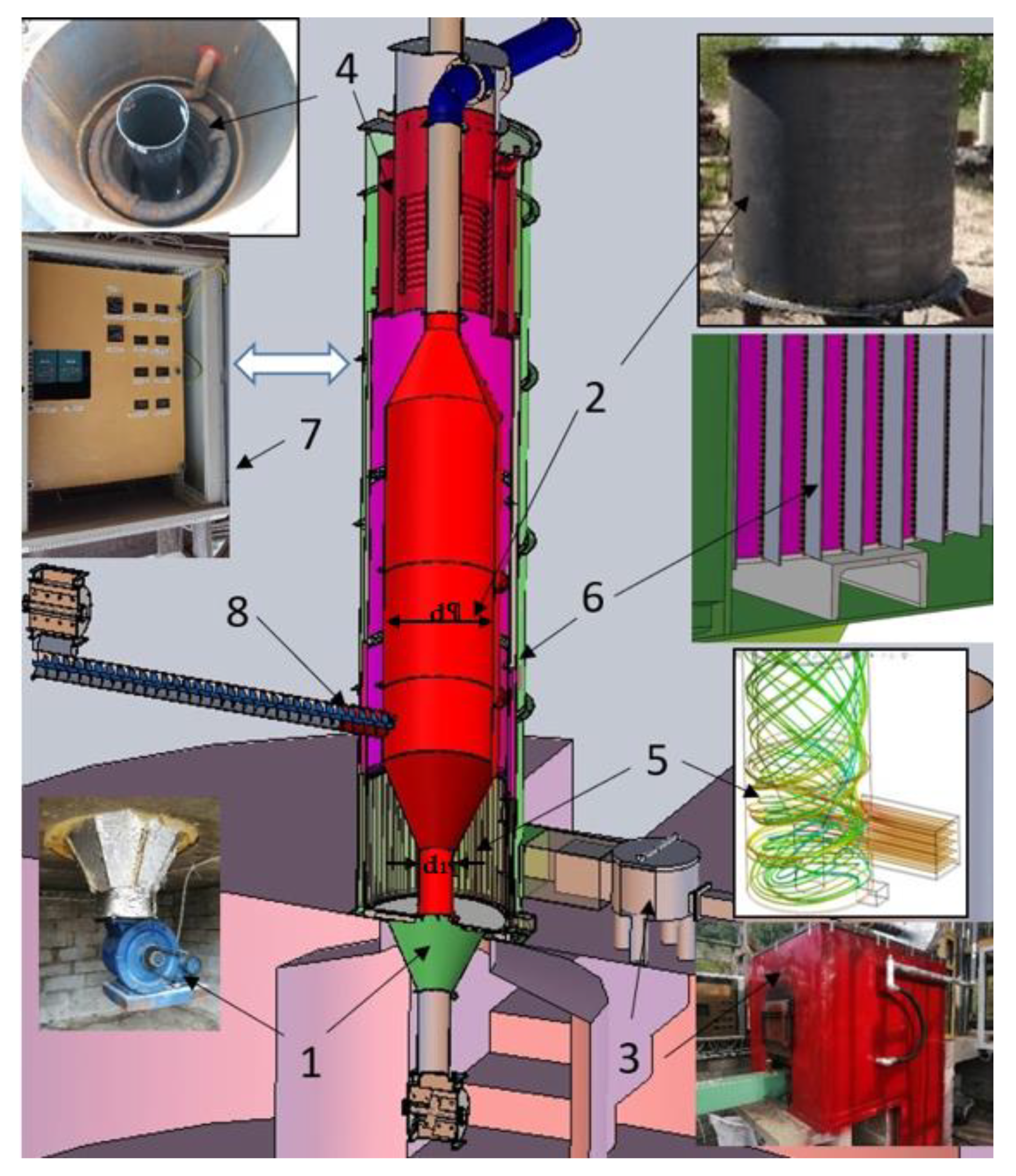
2. Materials and Methods

Pine sawdust obtained from various sawmills located in the Knyszynska Forest in Poland was collected and used for this research work.
In order to characterize the wooden chips obtained, the following tests were carried out before and after drying in the fountain dryer test stand: microscopic observations by means of SEM-EDS (Hitachi S-3000N, Tokyo, Japan) and optical microscope (Olympus 2000, Tokyo, Japan), specific surface area measurements of the sawdust by means of the BET method; size distribution of wet and dried sawdust using the ImageJ program; sawdust of drying process (drying curves) as described in the literature [15]. A laser particle size analyzer Analysette 22 Microtec, Fritsch, Germany was used to analyze the particle size distribution of the ash. Material collected from the dryer exhaust gas chamber (14, Figure 1) was taken for testing. Five tests were carried out, the data from which were averaged, and on their bases, a graph of ash particle size distribution was made. To determine the chemical composition of sawdust after drying, content of P, S, Cl and other metals, X-ray fluorescence spectrometry (XRF) and atomic absorption spectrometry (AAS) were used. Nitrogen content was detected by the Kjeldahl method. The carbon content was measured using the TOC Analyzer Multi N/C apparatus.

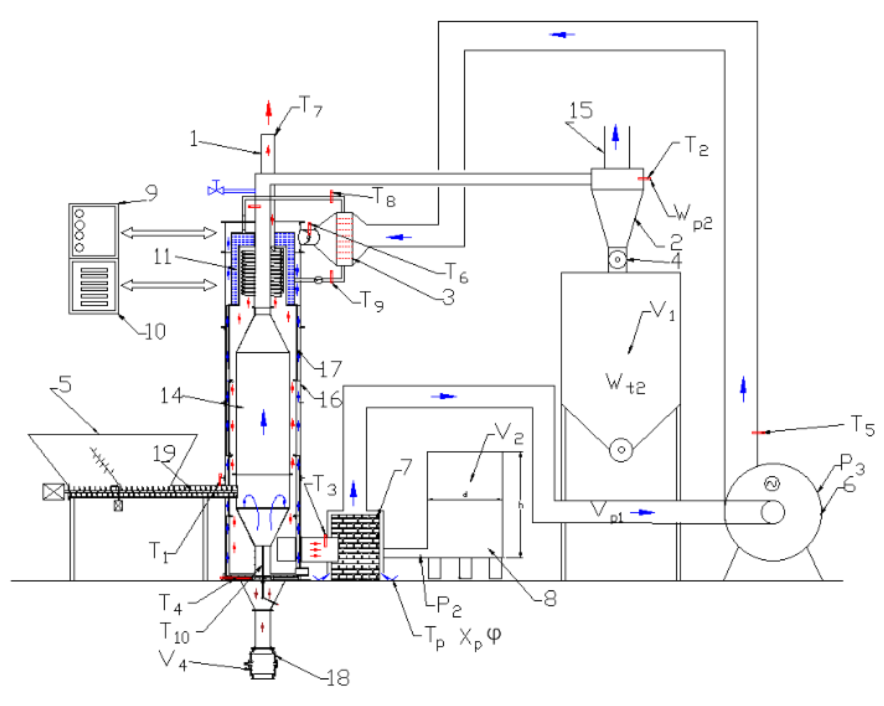
Description of the Test Stand of the Fountain Dryer

Figure 1 shows a schematic view of the fountain dryer equipped with detectors. The overall dimensions of the dryer stand is as follows: total height is 5.3 m, width 1.2 m, and length 5.0 m. Drying capacity of the device is about 300 kg/h. The dryer is equipped with a furnace with a gutter burner with a power of 200 kW and is controlled by a JC480 controller. The heating stove is powered with a pine sawdust. An average electricity consumption of the fountain dryer (screw drive, control, fan blowing among others) is 2 kW/h. As a drying medium, hot air is used, obtained through a heat exchanger between the flue gases from the furnace and blown air supplied from the outside. The air is heated inside the dryer column 14 (Figure 1), which means that the flue gases leaving the furnace do not come into contact with the chips. This solution can obtain the dried sawdust without color changing and exhaust gas toxic contaminants. The heat from exhausting is used to reheat the cold intake air. The device is covered with insulation (stone wool-fire protection 100 mm) to reduce a heat loss.
In addition to using the basic elements of a typical fountain drier, i.e., furnace 7, fan 6, drying chamber 14, sawdust screw feeder 19, cyclone 2 [8], the device has been additionally equipped with a heat recovery system 11 (Figure 1) and a system for capturing exhaust pollutants, presented and discussed in Section 3.
In addition, the dryer has an impurity separation system (rotary sluice 18, Figure 1) collecting sand, bark, stones, and other pieces of wood from the chips and sawdust by gravity.
The downcast fan 6 sucks fresh air through the outer jacket of the heating furnace 7 and therefore preliminary heats the air to temperature ~60 °C, measured with a thermocouple T5. The warm air is forced through the heater 3 into the dryer. The air heater 3 additionally increases the air temperature by 5–18 °C, detected by a thermocouple T6. Then, the warm air is blown between the outer shell 16 and the ribbed inner shell 17 where the temperature steadily increases, as it is detected by a thermocouple T4. The air is heated as a result of heat exchange between the ribbed surface of the internal case (Figure 1, point 17 and Figure 2, point 6) heated by exhaust gases. The movement of the heated air is counter-current to the movement of the flue gases and is separated by a jacket 17. The highest recorded temperature, introduced into the drying chamber 14 was 200 °C (thermocouple T10), where the air enters the drying chamber from the bottom. At the same time, the furnace is heated up to 850 °C, measured by the thermocouple T3. Inside the drying chamber 14, the drying process of sawdust takes place, supplied from the container 5 by the screw feeder 19. The screw feeder has a specially reduced stroke in order to seal the drying chamber to prevent air from leaking. Air exhausts can cause a fire hazard and interfere with the operation of the fountain dryer. The dried sawdust and moist air flow together into the cyclone 2, where the sawdust separation process takes place. The humid air is exhausted to the atmosphere through the outlet 1. The hot exhaust gas from the furnace is spinning from the lower to the upper part of the dryer (see 5 in Figure 2) between the jacket 17 and the inlet chamber 14. In the upper part, the exhaust gases pass through the water exchanger 11 and then goes outside through the outlet pipe 15. The airflow in the dryer chamber is controlled by means of an inverter controlling the fan speed, whereas the amount of sawdust fed is adjusted by an inverter controlling the rotational speed of the screw feeder 19.
The dryer, due to the gravity separator with rotary sluice 18, separates large pieces of wood and other impurities, which are periodically emptied by the operator and can be reused for combustion in the heating furnace 7. The heating furnace 7 is also the authors’ own design, adapted to burning the wasted sawdust. The furnace is additionally equipped with a volatile particle settler and is thermally insulated with an outer jacket where, initially, cold air is heated. This solution allows the heat to be collected from the furnace casing for preheating the air. The recovered heat in the kiln jacket was found to be 16.6% of the total efficiency.
A detailed schematic view about the system of air flow and hot exhaust gases in the dryer is shown in Figure 2 along with the description. The water heater 4 (Figure 2) recovers the remaining heat from the exhaust gases flued to outside the dryer. The hot water is then used to power the air heater (Figure 1, Figure 2 and Figure 3).
The drying chamber has a diameter ratio d/d1 equal to 3.3 (see Figure 2), which is a slightly higher value compared to the dryer described by R. Renström et al. [7], where this ratio is 2.64 and has no nozzle or partition inside the drying chamber. The height of the chamber (3.65 m) was determined experimentally and is within the range specified in the literature [2] for such a diameter ratio.

3. Results and Discussion

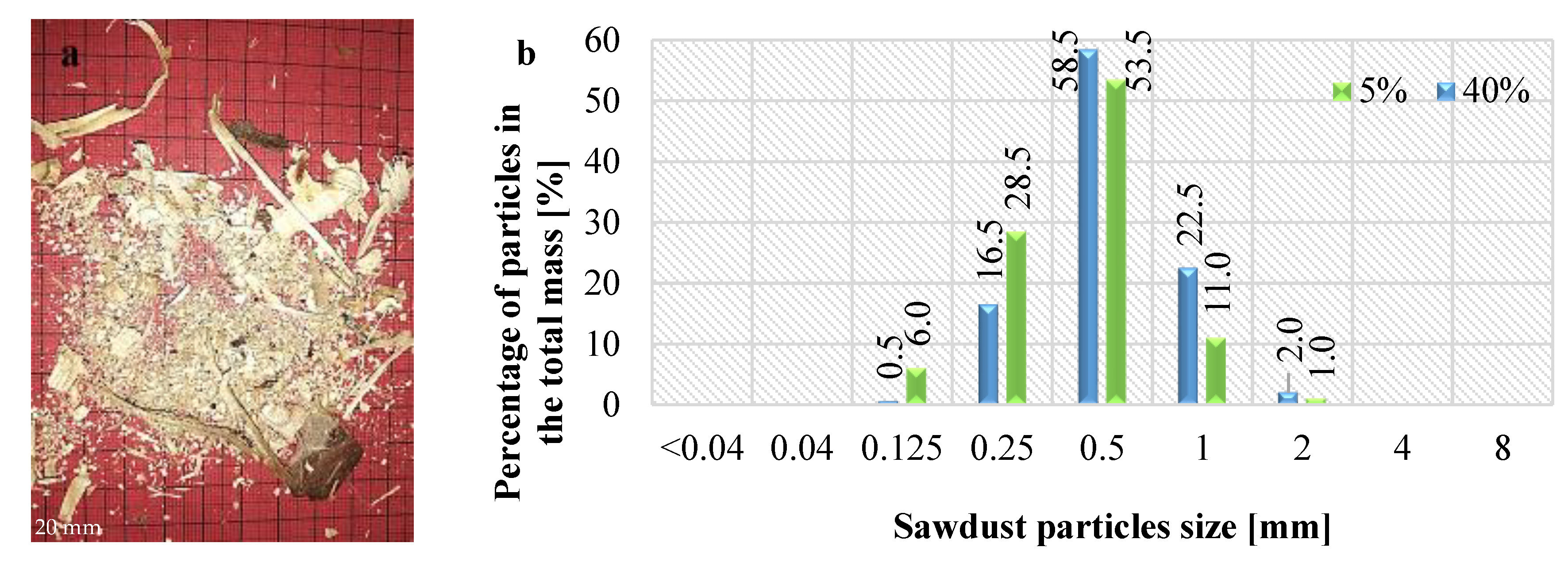
3.1. Sawdust Characterization

Figure 3a shows an image of a mixture of the wood chips/sawdust obtained from various sawmills and used for further investigation. Note that the morphology of these chips/sawdust is varied, although it is dominated by fine particles, after cutting with a band saw. Thus, the tested sawdust has bimodal-like distribution, of larger (above 5 mm) and smaller pieces. For further laboratory tests, a selected sawdust sample free of large pieces was used (Figure 3b), which was sieved in order to obtain a more homogeneous sample, which will take place in the designed device after gravitational separation.
The histogram of the sieved sawdust distribution before and after drying with a moisture content of 40% and 5% is shown in Figure 3b. It can be concluded that the average wet sawdust size is approximately 20% larger than the dry one probably due to crushing and cracking of the sawdust occurring during the drying process.
After drying, the specific surface area of sawdust reduced about 10%, from 0.5826 to 0.5233 (m2/g) for a dry and wet sample with 5% and 40% of humidity, respectively.
The chemical composition of the sawdust is summarized in Table 1, after drying it at 105 ± 1.5 °C up to 12% ± 1.5% of moisture content. For comparison, literature data are also presented [16,17].
From the results presented in Table 1 one can conclude that the chemical composition of pine sawdust significantly differs from the data presented in the literature. A significant decrease in such elements as Cu, Fe, Zn, and Mn, and an increase in the content of such elements as K, P, Ca, N or Mg are observed. The nitrogen content in the tested sawdust should be considered high. This can be explained by the fact that in the cited papers [16,17], the chemical composition after drying was tested separately for core, bark, and branches, whereas in this study, mixed sawdust from different areas of the pine tree was analyzed.
It is well known that the content of inorganic elements and sand and thus ash after burning wood or pellet, is many times higher in the bark than in the core of trees, which has a significant influence on the amount of these elements in the tested material here, compare to the literature data [16,17].

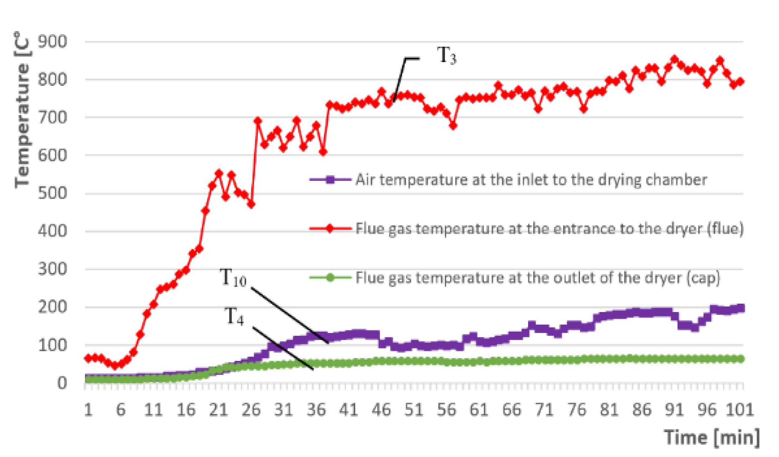
3.2. Determination of Air and Exhaust Gas Temperatures and Flow in Different Places of the Designed Dryer

Regarding the individual measuring points T1–T10, marked in Figure 1, K-type thermocouples were placed, and their indications were read at 5 s time intervals. Figure 4 shows the temperature increase vs. time at the three most important measurement points of the dryer. The red line shows (T3) the flue gas temperature inside the furnace at the entrance to the dryer. The green color line (T4) indicates the exhaust gas temperature at the outlet of the dryer. In the purple line, the temperature on the enter of the drying chamber (T10) is measured. These tests were used to determine the temperatures in the essential parts of the device and to determine the drying time of the dryer to the operating temperature. The temperature changes obtained by the measurements were helpful in assessing the operation parameters of the dryer. They were also used as boundary conditions in the computer simulations in SolidWorks Flow Simulation program. In addition, it was possible to assess, for example, the temperature in hard-to-measure points of the dryer, as well as direction of the flue gas movement inside the dryer (turbulence, speed, etc.).
The temperature changes presented in Figure 4 show the speed at which the device heats the air from the ambient temperature to the assumed operating temperature of ~200 °C. This parameter shows the time when there is the greatest demand for thermal energy for sawdust drying. During this period, the greatest demand for combustion energy of the furnace supplying the dryer occurs, with relatively low efficiency of the dryer. This period should be shortened as much as possible. Note that the temperature of 100 °C of cool air from the fan can be obtained after about 30 min of the furnace working. The temperature of 200 °C inside the drying chamber is reached after approximately 80 min of operation. The flue gas temperature at the entrance of 750 °C is reached after 35 min of the furnace operation. These temperature diagrams also show that the temperature of 200 °C inside the drying chamber was obtained at a flue gas temperature of 800–850 °C.
Further analysis of the results presented in Figure 4 revealed fluctuations in temperature inside the drying chamber and instabilities in exhaust gas temperatures at the entrance of the dryer. These temperature fluctuations in the first case are probably caused by discontinuous feeding of sawdust by the screw. Flue gas temperature instability at the entrance to the dryer probably results from the non-linear performance characteristics of the furnace controller.
During the measuring period, the temperature increases in the individual sections of the dryer, of which it is appropriate to locate the water heater at the very beginning of the air heating process. This is due to a slight difference in temperature between the air in front of the heater and the water temperature (~5 °C). The water heater located at the air inlet would probably better cool the water in the heat recovery system.
The heating furnace demand for fuel (sawdust) was also determined by measuring the volume loss of sawdust in the tank supplying the dryer, which is needed to heat the furnace from 20 to 200 °C within 1.0 h. The demand for sawdust during start-up was V2 = 0.14 m3/h, and during a stable operation was reduced by half to V2 = 0.07 m3/h. This decrease is because at the beginning, the elements of the dryer are cold and are warming up, and the furnace operates in a continuous mode. After warming up the elements, the furnace works only to maintain the set of the drying temperature.
The spinning motion flow of the exhaust gas inside the dryer was also analyzed by means of a SilidWorks Flow Simulation (CFD analysis) computer program, of which is presented in Figure 5a. This program performs calculations based on Navier–Stokes equations. The aim of the simulation was to find the speed and direction of the exhaust gas and airflow inside the dryer. The movement and impact of sawdust were not considered in this simulation. The wall conditions were assumed to be perfectly smooth. Air, exhaust, and material properties were selected from the Solid Works database.
The following boundary conditions were adopted:
-
the inlet exhaust gas temperature T3 = 750 °C;
-
the exhaust gas flow Vg = 0.122 m3/s;
-
the airflow Vs = 0.316 m3/s;
-
a water temperature in the water exchanger T8 = 75 °C;
-
the ambient temperature T0 = 20 °C.
The furnace gas flow measurements were taken at the dryer outlet. At this point, the flue gas has a temperature of approximately 70 °C, with the temperature of the flue gas leaving the furnace at about 750 °C. The diameter of the pipe at the flue gas outlet is 0.2 m. On the other hand, an appropriate design of the inlet of the dryer causes the flue gas to spin, which enables the cold air inside the pipe to be heated evenly and quickly. In addition, this movement additionally makes it possible to partially trap the volatile particles contained in the exhaust gas and settle them in the settling tank at the bottom of the dryer.
The fountain dryer has been equipped with a system for capturing dust and volatile particles from the exhaust gases produced after burning sawdust. The literature reports show that they are harmful to health and should not be emitted into the atmosphere [18]. This is performed by swirling the flue gases in the settling tank in settling tank 5. The captured particles were analyzed for particle size distribution, the results of which are shown in Figure 5b.
The diagram in Figure 5b shows that due to the centrifugation of the exhaust gas, it was possible to mainly reduce the emission of particles with sizes of 10–100 μm. Measurements were performed with a laser particle sizer analyzer (Analysette 22 Fritsch, Germany). When sawdust is dried directly with the exhaust gas, such as in a drum dryer, these particles build up on the sawdust and contaminate it. In addition, the environmentally harmful particles do not enter the atmosphere, which has an important impact on environmental protection. In this case, hot air heated by exhaust gas is used for drying.
On the basis of the exhaust gas flow measurements, the value of 3.9 m/s was obtained, with the temperature at the outlet reaching 73.1 °C. From the computer simulation analysis, the exhaust gas velocity at the inlet reaches 4 m/s, and then, it decreases two-fold. In the higher part of the dryer, the velocity decreases to about 2.1 m/s, which has a positive effect on the extension of the heat exchanging time.

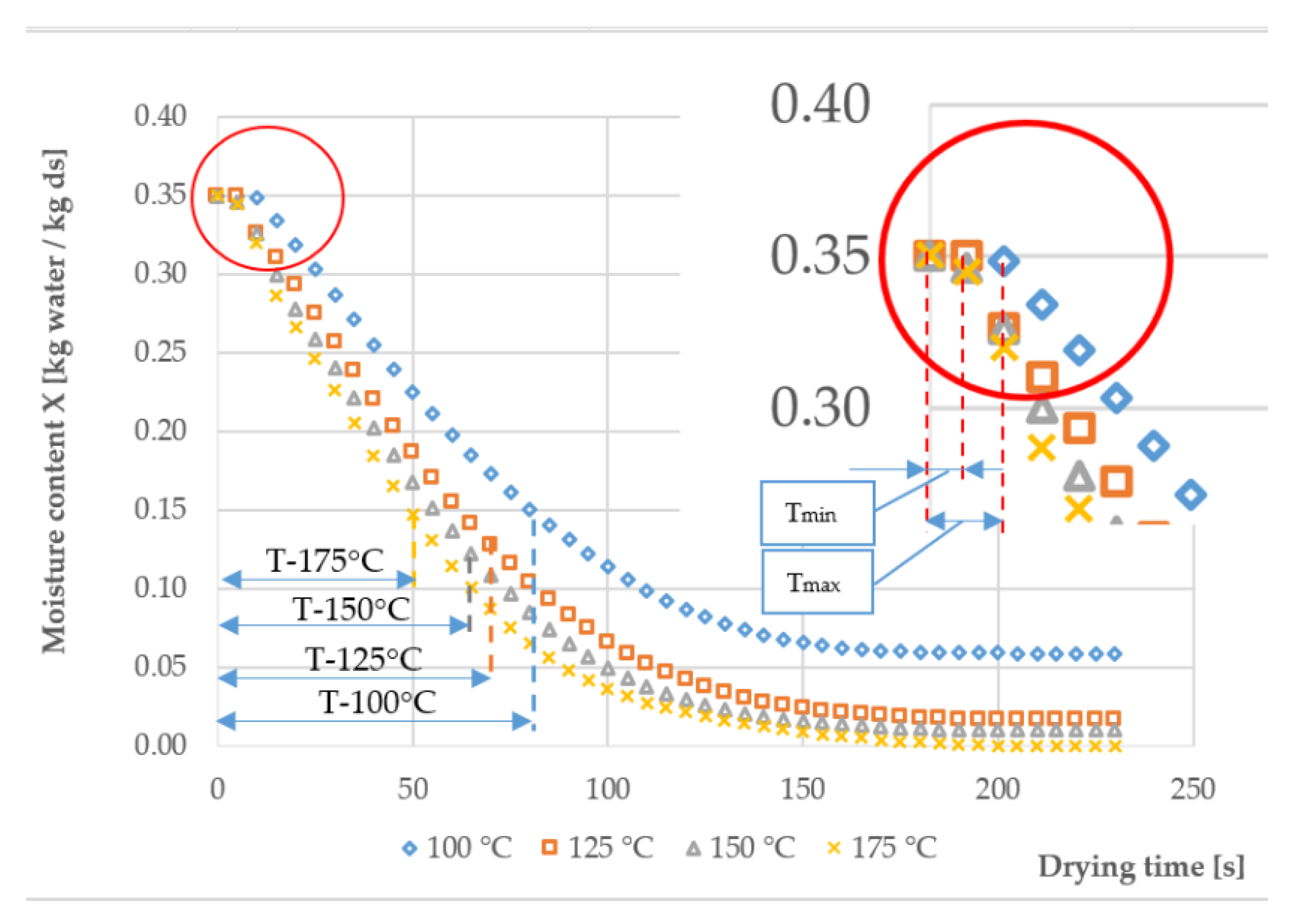
3.3. Drying Characteristics of Sawdust

The drying curves, in general, describe changes in the moisture content of the raw material per unit of time. The sawdust moisture prior to testing was about 35 ± 2%. Five trials were performed for each temperature, and the results were averaged. The detailed procedure for determining the curves is described elsewhere [19]. The screw feeding time was 30 s, during which the average weight of sawdust forced into the dryer was 4.75 kg. Then, the set drying temperatures were, accordingly: 100, 125, 150, and 175 °C (±2 °C), and the airflow speed was adjusted to 0.334 m3/s. After the operating temperature of the device stabilization, the weight of the dried sawdust was measured. The process of drying sawdust as a function of time and temperature is shown in Figure 6.
The graphs presented in Figure 6 show that it was only possible to dry wet sawdust to a moisture content close to 0% by using the temperature of 175 °C. As expected, the highest moisture content of 5.6% was measured after about 180 s of drying at the temperature of 100 °C. The remaining curve trends are similar, and the average moisture content of the sawdust is about 3.1 ± 1.5%. Note that the moisture content for pellet production is usually in the range of 8–10%. Therefore, the drying time is determined by the initial and final humidity of the sawdust.
It is noteworthy that the period of inertia of a given mass of sawdust heating is visible (see the enlarged beginning of the chart). This time is from 5 to 10 s (from Tmin to Tmax). The higher the drying temperature, the shorter the time of the process. Moisture evaporation during this period is very low. The drying curves also revealed that the drying time, for example for 15% humidity, varies from 78 to 49 s, for 100 and 175 °C, respectively, and comparing these results with other research works [15], it should be stated that the drying time of the shavings of 15% moisture content is comparable, or in comparison with the literature [15,20,21], is even shorter.

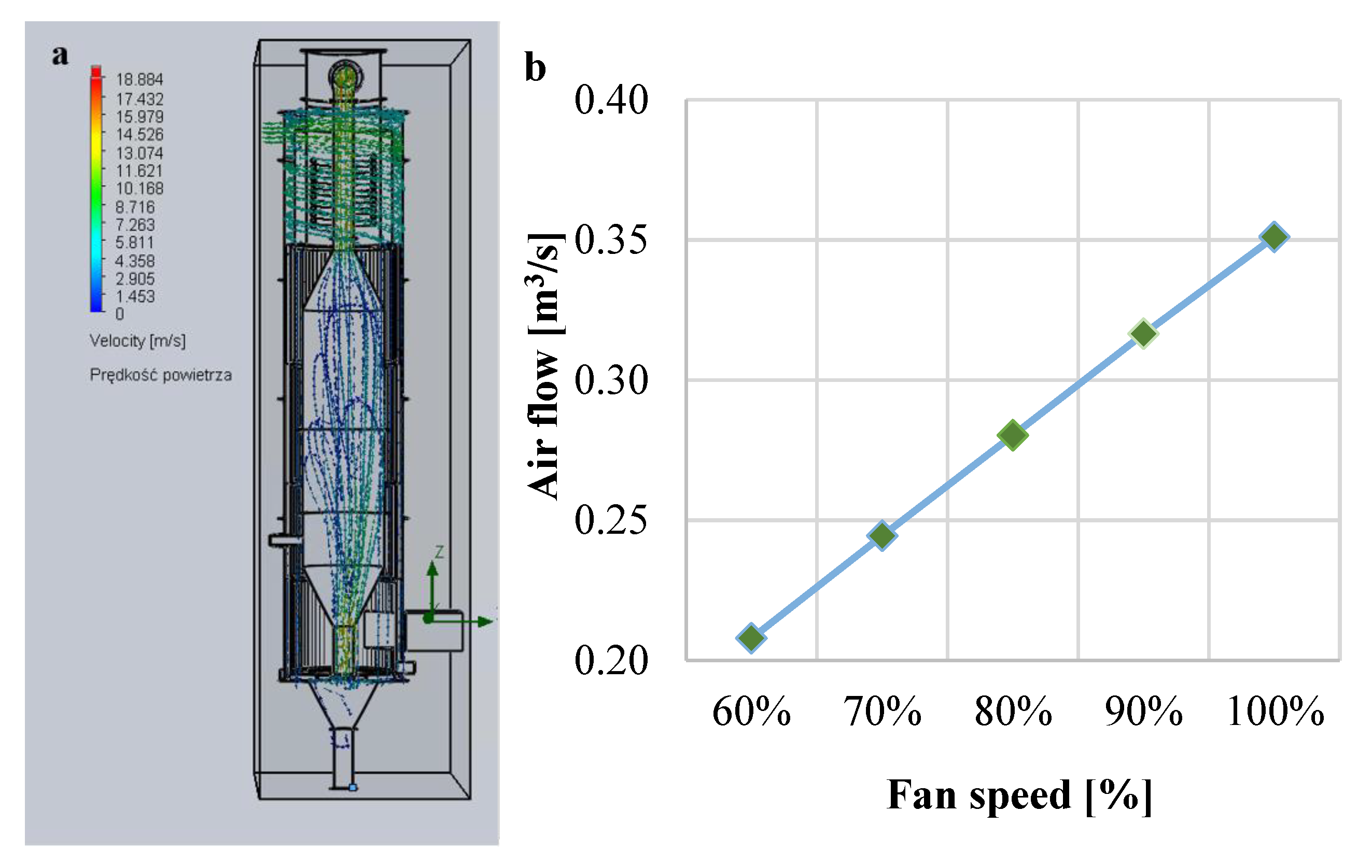
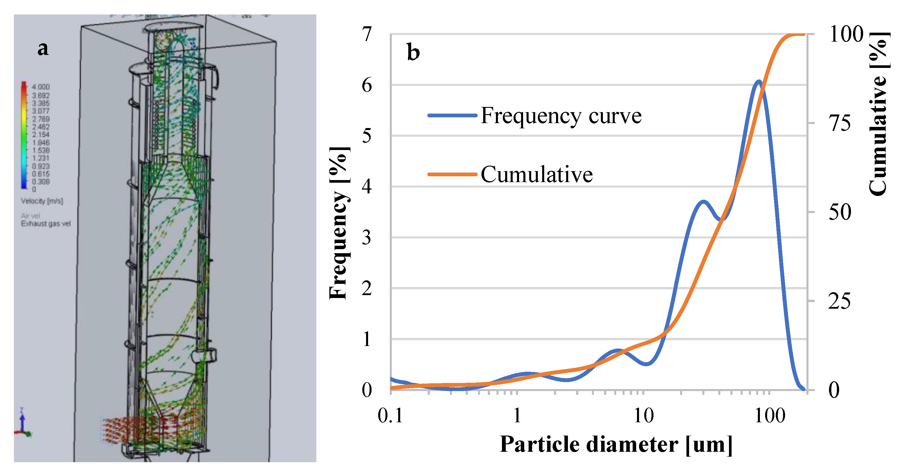
3.4. Characteristics of Airflows

Airflow pressure measurements were made using a VOLTCRAFT VPT-100 pressure hydrometer. Measurements were made at selected points located at the entrance and exit of the fountain dryer. The collected measurement data were also used for the computer simulation of the flows (Solidworks Flow Simulation). The measurement was made in a pipe with a diameter of 160 mm at the outlet of the fan with an average air temperature of 23 ± 1 °C.
The data presented in Figure 7a,b show that for 90% of the fan settings, the airflow is 0.316 (m3/min). Computer simulations (see Figure 7a) performed for the airflow velocities inside the drying chamber are made for the temperature of the combustion gases, which is equal to 850 °C. Analyzing the simulation presented in Figure 7a, one can see that the air velocity inside the drying chamber is about 2.9 m/s, whereas the velocity in the outer casing (16, 17) is 1.5 m/s, which is twice as slow. This is an intended design effect aimed at extending the air heating time. The air inside the drying chamber has turbulence, which contributes to better mixing of the raw material inside the chamber.
One can also observe a slight deviation in the air stream to the right. This phenomenon is not favorable and is caused by a bent pipe mounted above the dryer, which directs sawdust further into the cyclone.
The airflow rate influences the moisture content of the sawdust at the dryer outlet. In the case of too high moisture content of the sawdust, an operator can reduce the amount of the wet material fed. In order to remove the so-called phenomenon of levitating chips, described in the literature [22], the dryer controller can periodically (e.g., every 1 h) reduce the amount of air to 20% for 15 s, turning off the sawdust feed; thus, the levitating impurities can fall into the separator 1 (Figure 2). The sawdust collected in this way can be periodically selected and reused for burning in a drying furnace. This solution prevents the risk of fire and cleans the fountain bed from contamination, providing a good quality material for further granulation processes.

4. Conclusions

The information included in this work confirmed that it is possible to modify the fountain dryer, which can dry non-homogeneous materials, e.g., sawdust and chips, and from the obtained material, it is possible to obtain high-quality fuel. Therefore, the dryer is additionally equipped with functional sections, such as: impurity separation from the sawdust, a heat exchanger, a system of heating the air from the exhaust gases inside the dryer column, and a system for separating fine volatile particles from exhaust gases. Thus, the exhaust gases do not contaminate the dried material, and an additional process of separating sand and larger pieces of wood is not necessary.
The obtained results presented here revealed that the maximum measured combustion of sawdust during startup of the furnace was 0.14 m3/h, which is 0.46 m3 of the fuel consumption for the production of 1000 kg of sawdust, with a final moisture content of ~15%. Combustion in conventional drum dryers ranges from 1 to 1.2 m3 for drying 1000 kg of sawdust with a similar initial and final moisture content of 40–50% and 15%, respectively.
Drying time of wet sawdust is relatively short and takes ~50 s (weight of wet sawdust 4.75 kg, 35% of moisture) at a relatively low air temperature of 175 °C, which is important in the case of self-ignition of the sawdust. Furthermore, emissions of the fine volatile particles contained in the exhaust gases have been reduced.
The temperature of 200 °C inside the drying chamber was reached after 5000 s of dryer operation for exhaust gas temperatures in the range of 800–850 °C.
The exhaust gas flow velocities, both calculated and measured, are comparable, and computer simulations of hot air flow inside the drying chamber confirmed the correctness of the design assumptions.
By controlling the airflow, it is possible to solve the problem of levitating chips that can cause a fire in this king of fountain dryers.
Temperature measurements in various places of the dryer showed that the heat recovery system works properly; however, during long-term operation, the water in the recovery heat system may boil. Therefore, the water heater system should be placed on the air inlet, which should improve the heating of the air and better dissipate heat from the water. In this place, a greater temperature difference between the water in the air heater and the ambient temperature can be obtained. This should result in better cooling of the water and improved heater efficiency.
The device requires a relatively small installation space, which is important in the case of fuel pellet production. The modular structure of the dryer allows for easy assembly and transport of the device, because the dryer does not require cranes and other specialized devices during assembly.

Author Contributions

Conceptualization, K.R. and Z.O.; software, K.R.; validation, K.R. and Z.O.; formal analysis, Z.O.; investigation, K.R. and Z.O.; resources, K.R.; data curation, K.R.; writing—original draft preparation, K.R. and Z.O.; writing—review and editing, Z.O.; visualization, K.R.; supervision, Z.O.; project administration, K.R. All authors have read and agreed to the published version of the manuscript.

Funding

This research received no external funding.

Data Availability Statement

No new data were created or analyzed in this study. Data sharing is not applicable to this article.

Conflicts of Interest

The authors declare no conflict of interest.

Nomenclature

ddrying chamber diameter
d1diameter of the inlet to the drying chamber
Vsair flow (m³/s)
Vgflue gas flow (m³/s)
Svelocity (m/s)
ttime (s)
Yhumidity (%)
Ttemperature (°C)
VoSample volume (m3)
Welectrical power (kW)
φthe air humidity (%)
Xbhumidity (kgwater/kgds)

References

  1. Frodeson, S.; Berghel, J.; Renström, R. The Potential of Using Two-Step Drying Techniques for Improving Energy Efficiency and Increasing Drying Capacity in Fuel Pellet Industries. Dry. Technol. 2013, 31, 1863–1870. [Google Scholar] [CrossRef]
  2. Mujumdar, A.S. Handbook of Industrial Drying; CRC Press: Boca Raton, FL, USA, 2006. [Google Scholar]
  3. Brammer, J.G.; Bridgwater, A.V. Drying technologies for an integrated gasification bio-energy plant. Renew. Sustain. Energy Rev. 1999, 3, 243–289. [Google Scholar] [CrossRef]
  4. Pablos, A.; Aguado, R.; Vicente, J.; Altzibar, H.; Bilbaoa, J.; Olazar, M. Effect of operating conditions on the drying of fine and ultrafine sand in a fountain confined conical spouted bed. Dry. Technol. 2020, 38, 1446–1461. [Google Scholar] [CrossRef]
  5. Estiati, I.; Tellabide, M.; Saldarriaga, J.F.; Altzibar, H.; Olazar, M. Influence of the fountain confiner in a conical spouted bed dryer. Powder Technol. 2019, 356, 193–199. [Google Scholar] [CrossRef]
  6. Sukunza, X.; Pablos, A.; Aguado, R.; Vicente, J.; Bilbao, J.; Olazar, M. Effect of the solid inlet design on the continuous drying of fine and ultrafine sand in a fountain confined conical spouted bed. Ind. Eng. Chem. Res. 2020, 59, 9233–9241. [Google Scholar] [CrossRef]
  7. Renström, R.; Berghel, J. Drying of sawdust in an atmospheric pressure spouted bed steam dryer. Dry. Technol. 2002, 20, 449–464. [Google Scholar] [CrossRef]
  8. Jia, D.; Cathary, O.; Peng, J.; Bi, X.; Lim, J.; Sokhansanj, S.; Liu, Y.; Wang, R.; Tsutsumi, A. Fluidization and drying of biomass particles in a vibrating fluidized bed with pulsed gas flow. Fuel Process. Technol. 2015, 138, 471–482. [Google Scholar] [CrossRef]
  9. Bergström, D.; Finell, M.; Gref, R. Effects of extractives on the physical characteristics of scots pine sawdust fuel pellets. For. Prod. J. 2010, 60, 640–644. [Google Scholar] [CrossRef]
  10. Ståhl, M.; Granström, K.; Berghel, J.; Renström, R. Industrial processes for biomass drying and their effects on the quality properties of wood pellets. Biomass Bioenergy 2004, 27, 621–628. [Google Scholar] [CrossRef]
  11. Berghel, J.; Renström, R. An Experimental Study on the Influence of Using a Draft Tube in a Continuous Spouted Bed Dryer. Dry. Technol. 2014, 32, 519–527. [Google Scholar] [CrossRef]
  12. Vigants, E.; Vigants, G.; Veidenbergs, I.; Lauka, D.; Klavina, K.; Blumberga, D. Analysis of energy consumption for biomass drying process. Vide. Tehnol. Resur.-Environ. Technol. Resour. 2015, 2, 317–322. [Google Scholar] [CrossRef]
  13. Gupta, C.K.; Sathiyamoorthy, D. Fluid Bed Technology in Materials Processing; CRC Press: Boca Raton, FL, USA, 1999. [Google Scholar]
  14. Kutz, M. Handbook of Farm, Dairy and Food Machinery Engineering; Academic Press: Cambridge, MA, USA, 2019. [Google Scholar]
  15. Moreno, R.; Rios, R. Study on sawdust drying techniques in fluidised bed. Biosyst. Eng. 2002, 82, 321–329. [Google Scholar] [CrossRef]
  16. Skonieczna, J.; Małek, S.; Polowy, K.; Węgiel, A. Element content of Scots pine (Pinus sylvestris L.) stands of different densities. Drewno 2014, 57, 77–87. [Google Scholar] [CrossRef]
  17. Saarela, K.E.; Harju, L.; Rajander, J.; Lill, J.-O.; Heselius, S.-J.; Lindroos, A.; Mattsson, K. Elemental analyses of pine bark and wood in an environmental study. Sci. Total Environ. 2005, 343, 231–241. [Google Scholar] [CrossRef] [PubMed]
  18. Vicente, E.D.; Vicente, A.M.; Bandowe, B.A.M.; Alves, C.A. Particulate phase emission of parent polycyclic aromatic hydrocarbons Particulate phase emission of parent polycyclic aromatic hydrocarbons (PAHs) and their derivatives (alkyl-PAHs, oxygenated-PAHs, azaarenes and nitrated PAHs) from manually and auto deri. Air Qual. Atmos. Heath 2016, 9, 653–668. [Google Scholar] [CrossRef]
  19. Spreutels, L.; Haut, B.; Chaouki, J.; Bertrand, F.; Legros, R. Conical spouted bed drying of Baker’s yeast: Experimentation and multi-modeling. Food Res. Int. 2014, 62, 137–150. [Google Scholar] [CrossRef]
  20. Olazar, M.; Lopez, G.; Altzibar, H.; Amutio, M.; Bilbao, J. Drying of Biomass in a Conical Spouted Bed with Different Types of Internal Devices. Dry. Technol. 2012, 30, 207–216. [Google Scholar] [CrossRef]
  21. Chen, D.; Zheng, Y.; Zhu, X. Determination of effective moisture diffusivity and drying kinetics for poplar sawdust by thermogravimetric analysis under isothermal condition. Bioresour. Technol. 2012, 107, 451–455. [Google Scholar] [CrossRef] [PubMed]
  22. Rojcewicz, K.; Oksiuta, Z. Viability analysis of pine sawdust drying in a fountain dryer. Tech. Sci. 2020, 23, 263–280. [Google Scholar] [CrossRef]
Figure 1. Schematic view of the dryer with marked measurement places: 1: moist air outlet; 2: cyclone; 3: air heater; 4: rotary outlet for sawdust; 5: raw material tank; 6: blower; 7: furnace; 8: furnace supply tank; 9: measuring devices; 10: control devices; 11: water heat exchanger; 12: conical separator; 13: dry sawdust tank;14: dying chamber; 15: outlet pipe; 16: external case; 17: internal case; 18: rotary sluice; 19: screw feeder; Tp: air temperature (°C); φ: the humidity control point of the air entering the dryer; X1: moisture of sawdust on the entrance (%); X2: moisture of sawdust on the exit (%); T1: sawdust temperature at the entrance (°C); V1: volume of dried sawdust (m3); Vp1: airflow V2: volume of sawdust used for combustion (m3); V3: volume of wet sawdust (m3); V4: volume of waste (m3); T1: Sawdust temperature measure at the entrance (°C); T2: air temperature measure point at the entrance to the drying chamber (°C); T3: exhaust gas temperature measured at the entrance to the dryer (°C); T4: air temperature at the exit from the chamber (at the end of the ribbed surface) (°C); T5: air temperature before air heater (°C); T6: air temperature before water heater(°C); T7: air temperature at the exit from the dryer (°C); T8: water temperature before air heater (°C); T9: water temperature after air heater (°C); T10: air temperature in the dying chamber (°C) Xp: Fuel moisture; φ: air humidity; Wp2: air humidity (steam); Wt2: moisture content in dried sawdust; P3: screw conveyor rotational speed; P3: fan speed.
Processes 11 00430 g001
Figure 2. The fountain dryer modified parts. 1—dirt separator; 2—drying chamber segment; 3—furnace for burning waste; 4—water heat exchanger; 5—direction of exhaust gases in the drying chamber; 6—ribbed heating surface; 7—measuring cabinet; 8—variable pitch screw feeder.
Processes 11 00430 g002
Figure 3. (a) Mixture of a pine sawdust collected in this work. (b) Histogram of the sawdust size distribution with the humidity of 5% and 40%, respectively.
Processes 11 00430 g003
Figure 4. Temperature increase vs. time at 3 measuring points of the dryer: T3, T4 and T10.
Processes 11 00430 g004
Figure 5. (a) Computer simulation of the exhaust gas flow velocity inside the drying chamber. (b) Particle distribution obtained from the exhaust gas.
Processes 11 00430 g005
Figure 6. Drying curves of a wet pine sawdust tested at temperatures of 100, 125, 150 and 175 °C.
Processes 11 00430 g006
Figure 7. (a) Air velocity distribution inside the dryer. (b) Characteristics at the fan speed to the amount of airflow inside the dryer.
Processes 11 00430 g007
Table 1. Some elements detected in sawdust after drying up.
Element
(g/kg)
FeMnZnMgKCaPSCN
Tested0.1480.0980.0280.3950.7021.050.170.094293.33.2
From [16]0.1340.1500.1170.2700.2700.6500.0700.430470.00.830
From [17]0.3300.3100.150-0.6200.2100.1120.345--
Disclaimer/Publisher’s Note: The statements, opinions and data contained in all publications are solely those of the individual author(s) and contributor(s) and not of MDPI and/or the editor(s). MDPI and/or the editor(s) disclaim responsibility for any injury to people or property resulting from any ideas, methods, instructions or products referred to in the content.

