Article

Comfort Optimization of the Active Collision Avoidance Control System of Electric Vehicles for Green Manufacturing

School of Intelligent Manufacturing, Weifang University of Science and Technology, Shouguang 261000, China
*
Author to whom correspondence should be addressed.
Processes 2023, 11(2), 485; https://doi.org/10.3390/pr11020485
Submission received: 8 October 2022 / Revised: 20 January 2023 / Accepted: 30 January 2023 / Published: 6 February 2023
(This article belongs to the Special Issue Green Manufacturing and Sustainable Supply Chain Management)

Abstract

:
The vehicle model was built based on MATLAB/Simulink and Carsim, and the multi-objective active collision avoidance control algorithm considering safety and comfort was established based on a model predictive control (MPC) algorithm. The vehicle active collision avoidance control system for comfort and safety was studied by simulation and experimentation. The results show that the active collision avoidance control system based on an MPC algorithm can follow the vehicle under different working conditions and ensure the safety and comfort in the process of following the vehicle while meeting the requirements of the active collision avoidance control system.

1. Introduction

Vehicle active collision avoidance control technology is a new technology combining modern information technology, sensing technology, dynamic identification and control technology.
The vehicle active collision avoidance control system uses advanced information technology such as information processing technology and sensors to obtain external traffic environment information, such as relative speed and distance from pedestrians and front vehicles, and combines it with the driving conditions of self-propelled vehicles, so as to realize the identification of current vehicle safety risks. According to the degree of danger, corresponding control measures are automatically taken to ensure the safe operation of the car [1,2,3,4,5].
Domestic and foreign enterprises have conducted in-depth research on vehicle active collision avoidance systems. In Germany, by installing a range automatic control radar, the Mercedes-Benz BENZ 600S can adjust the vehicle’s speed in the speed range of 40–60 km/h to control the distance between the car and the front car. When the vehicle’s spacing is lower than the safe distance, the control mechanism is automatically controlled by the system to brake to reduce the collision with the front vehicle [6,7]. The German company Volkswagen developed Front Assist, a pre-collision safety system. At the speed of 0–30 km/h, the system detects the speed and distance of the front obstacle or vehicle by millimeter wave radar, to realize the prediction of collision accidents. When the car is undergoing emergency braking, the system will issue a warning signal. When the driver does not perform collision avoidance action, the system will automatically force the vehicle to brake [8,9]. In Japan, Toyota took the lead in developing the active safety collision mitigation braking system CMBS (Collision Mitigation Brake System) [10]. The sensors on the vehicle can detect the distance between the vehicle and other cars driving on the same road. When the distance between the vehicles is less than the safe range, there may be a rear-end accident. According to the alarm signal, the driver can understand the danger the vehicle is in. When the driver ignores the alarm signal and does not take corresponding measures, as the distance becomes closer and closer, the system will issue warnings, such as slight braking action of the brake. When the system determines that the vehicle cannot avoid a rear-end collision with the vehicle following behind, the brake light is lit first to inform the following vehicle that there may be danger. At the same time, the collision mitigation braking system can achieve emergency braking and minimize collision losses. At the same time, Toyota also developed the Pre-Collision System (PCS) [11]. The system detects the vehicle or obstacle ahead and calculates the distance from the vehicle by a millimeter wave radar installed at the head of the vehicle to calculate the probability of collision. In succession, Narayanan P [12] released a new concept, the FCAAC (Forward Collision Avoidance Assist Concept). This system uses radar to detect whether there are obstacles or other means of transportation in front of it and then calculates their distances by computer. When the distance between vehicles is less than the safe range, collisions may occur, and then auxiliary braking is taken. When the driver cannot control the vehicle in time, the system will control the corresponding actuator for braking control. This system can help vehicles with an initial speed below 57.6 km / h to avoid rear-end accidents.
In China, relevant researchers have conducted some research on the security of active obstacle avoidance systems, vertical and horizontal algorithms of active obstacle avoidance systems, etc. [13,14,15]. In 2008, Professor Chen Qian, Nanjing University of Science and Technology, and Anwei Fengyang jointly developed the first domestic “laser detection vehicle active anti-collision intelligent safety system” successfully. When the car is running at normal high speed, the driver often fails to handle the sudden obstacles ahead. The system can use lasers to collect the characteristics of multiple traffic environments and combine advanced signal analysis and processing technologies to achieve vehicle tracking, early warning, deceleration, braking and other operations. When the obstacle is cleared, the vehicle automatically returns to normal driving [16]. A comprehensive assessment method of vehicle longitudinal and lateral collision risk that considers both the simplicity of time–distance model calculation and the accuracy of motion model modeling is proposed by Qin et al. [17]. In order to better assess the collision risk and realize the conversion of different control modes, Yuan Wei and others [18] have combined the longitudinal driving safety factor and the reciprocal of the collision time. At the same time, there is almost no active collision avoidance system with multiple economic performance indicators. Due to the driving characteristics of the active collision avoidance function of electric vehicles, there are frequent addition, unstable deceleration and speed control and unnecessary energy [19] consumption loss in the process of collision avoidance [20].
To sum up, the current research on vehicle active collision avoidance control systems mainly considers the safety factors but less considers the comfort and other aspects. Therefore, this paper proposes research on vehicle active collision avoidance control systems for comfort and safety in view of the insufficient consideration of vehicle active collision avoidance control systems.

2. Conceptual Design

2.1. Software in the Loop Test Scheme Design

2.1.1. The First Section

This section introduces the study object, namely the selection of the vehicle. Compared with traditional cars, intelligent car testing pays more attention to the vehicle’s driving situation in different traffic environments and scenarios. The research object in this paper is pure electric vehicles with front-wheel centralized drive. The complete vehicle parameters are shown in Table 1.
Due to the needs of different stages of testing, a vehicle dynamics model was built in Simulink and CarMaker, respectively, and the main difference lies in the tire model. The tire model built in Simulink adopts the magic formula, from the slip rate s x , the tire side angle c x , the road adhesion coefficient μ and the ground normal reaction force F z , to obtain the longitudinal force F x and the lateral force F y . Professor H.B Pacejka of the Netherlands proposed a method to build a tire model. By fitting the experimental data of the trigonometric function, the mechanical properties of the tire in this case can be completely obtained. The “magic formula” parameter has clear meaning, wide range of use, high fitting accuracy and high confidence, which is suitable for the analysis and prediction of automotive dynamic simulation characteristics. In the model of this paper, it does not involve the analysis of the steering system, nor consider the equal torque effect, but only analyzes the longitudinal load, longitudinal slip rate and longitudinal stability.
When building tire models in CarMaker, there are several modeling methods, including real-time tire model (RealTime Tire), magic formula tire model and TameTire tire model. Among them, the real-time tire model is the empirical tire model provided by the IPG company, which is built based on the measured real-time data of the tire in operation. This kind of model provides a variety of commonly used tire models for research and development personnel to choose from. The magic formula tire model’s principle is the same as the previous paragraph: input for the parameters in the magic formula or the tire attribute file established in ADAMS. The TameTire tire model is a thermomechanical tire model provided by the Michelin R&D department, covering the transient mechanical properties and thermal properties of the tire, with the highest precision.
According to the braking force allocation strategy before and after ECE regulation, two allocation strategies are adopted in this paper: One is a distribution curve for the front and rear braking force distribution along the I curve, that is, the front and rear wheels cling at the same time. Another allocation strategy for braking is performed by using the front axle’s (motor) braking force as much as possible; with this allocation strategy, the front axle can brake as much as required by regulations to maximize the use of the motor for braking energy recovery. The electro-hydraulic distribution strategy of the front axle adopts the strategy of using motor braking as far as possible, when the target braking torque is less than the braking torque provided by the motor; when the target torque is exceeded by the motor, the motor emits the maximum braking torque, and the rest of the braking force is provided by the hydraulic braking system. When ABS is not enabled and the vehicle is locked, a pure hydraulic system is applied to prevent motor damage. Sensor setup is also required in CarMaker. Since this paper does not analyze the influence of the opening angle, installation position or characteristic parameters of the sensor on the control effect, the ideal sensor is used to obtain the movement of the front and rear vehicles and pedestrians through the global coordinates, including the position, speed, acceleration and other information.

2.1.2. The Construction of the Traffic Scenarios

After completing the setting of vehicle parameters, roads, environmental vehicles and pedestrians should be set up to build the intelligent vehicle test scene. Starting from CarMaker 6.0, the setting of scenes starts to support drag-and-drop creation, which is convenient for developers to create scenes faster and more intuitively.
The behavior setting of self-contained vehicles, traffic vehicles and pedestrians can be completed in CarMaker/Maneuver and CarMaker/Traffic. By setting the time, speed, acceleration, position, steering, termination conditions and jump conditions of each individual behavior, various complex working conditions can be flexibly realized. In addition, the behavior of each traffic element can be programmed more carefully in CarMaker/Maneuver. After completing a test condition setting, CarMaker/Test Manager can be used to automatically set the key parameters in this test condition to realize mass automatic testing. In addition, using TestManager can greatly simplify the construction process of the test scene, reduce the workload, reduce the required storage space, reduce the test cost and improve the test efficiency.

2.1.3. Joint Control Interface with the Simulink

CarMaker can generate models in Simulink format and convert the settings in CarMaker to S-Function in Simulink. At the same time, one can also use the Read CM dict module, input the variable name in the CarMaker and directly read the corresponding variables in Simulink. By using the Write CM dict module, the variables in CarMaker can be directly changed to achieve control.

2.2. Control Method Design of Longitudinal Active Collision Avoidance System Based on MPC

2.2.1. Construction of Vehicle Model

Carsim was used to establish the virtual environment and vehicle dynamics model of emergency collision avoidance conditions, and the required longitudinal braking safety distance model was built in Simulink. Through the powerful real-time interface function of Carsim and Simulink, the above models were connected to form a closed-loop simulation system. The collision avoidance mode was simply judged and selected, and the simulation test was carried out by setting typical working conditions.
The overall structure of the active collision avoidance control system is designed as shown in Figure 1:
The Blue circles represent the controller.The red square frame on the left side of the figure was built by Simulink. Similarly, the red square frame on the right side was built by Carsim. Here, S d e s represents the expected safety distance; v d e s represents the autopilot speed; a d e s represents the desired acceleration; a c o n represents the controlled quantity of the lower controller; P d e s represents the expected automatic driving brake pressure; P b represents the actual braking pressure of the car; v f represents the actual vehicle speed; a represents the actual acceleration of the car; ω e represents the engine speed; ζ represents the actual distance between the car and the front car.
When the vehicle is running, according to the different driving states of the front vehicle, the active collision avoidance control system will judge the safety state according to the environmental information, and the safety distance model calculates the safety distance under the current driving state in real time. By comparing with the actual vehicle distance, when the actual vehicle distance is less than or equal to the safe distance, the active collision avoidance control system will automatically judge the vehicle as being in a dangerous state. After the calculation of the hierarchical controller, the active collision avoidance control system acts on the vehicle dynamics system. The active collision avoidance control system will control the brake actuator to achieve the purpose of controlling the speed and ensuring the safety of the vehicle. The actuator controlled by the active collision avoidance control system is the brake. The brake realizes the desire to brake the pressure output and controls the deceleration of the car.

2.2.2. Algorithm Construction of Active Collision Avoidance Control System

Based on the MPC algorithm, a multi-objective active collision avoidance control algorithm considering safety and comfort is proposed. Secondly, for the poor robustness of MPC, a method based on state error correction is proposed to enhance the robustness of the system; then, the cost function is transformed into a quadratic form to obtain the optimal control sequence, and the first value is applied to the system to achieve the optimal purpose. Finally, the joint simulation results of CarSim/Simulink are verified.

Active Collision Avoidance Control Target Analysis

On the road, the most basic and important control objective of the active collision avoidance control system is safety. Therefore, strict constraint control of the actual workshop distance is the primary premise to ensure the safe operation of the active collision avoidance control system. In this paper, the workshop distance Δ d ( t ) is not less than the minimum safe distance d 0 :
So, the formula is: Δ d ( t ) d 0 .
The control objective of the active collision avoidance control system for the following distance is that the actual following distance between the self-driving car and the front car approaches the expected following distance: δ ( T ) 0 .
The control objective of the active collision avoidance control system for the car-following speed is to achieve the actual car-following speed equal to that of the head car, that is, the vehicle is in a relatively static state: υ r e l ( t ) 0 .
When the car’s acceleration and acceleration change rate are smaller, the passenger comfort will be higher [21,22]. The control objective of the active collision avoidance control system for comfort is to minimize the acceleration and acceleration change rate during driving: min a ( t )   min j ( t ) .
In MPC, the car-following process has dynamic characteristics. In order to prevent large input and output fluctuations in the car-following process, that is, to ensure the smooth car-following of the active collision avoidance control system in the car-following mode, we make the output L ( t ) reach the set value L r e f along the desired gentle curve, and the generated curve L r e f ( t ) is the reference curve. Along the reference trajectory L r e f ( t ) , each component of the output equation L ( t ) will be smoothly approached to 0. The reference curve is expressed in the first-order exponential form, as shown in Formula (1):
L r e f ( t + i ) = γ i L ( t ) + ( 1 γ i ) L r e f
where γ is the coefficient of the reference trajectory, usually between 0 and 1. The smaller the γ value is, the faster the reference trajectory is. The γ value is 0.9 [23].

Robust Design of Car following Model Prediction

In the actual system operation, due to the internal uncertainty of the system, such as vehicle parameter measurement error, parameter estimation error, parameter time varying, model adaptation, unmodeled dynamics and external interference [24,25,26], there is always model uncertainty in the car-following system. Uncertainty makes the prediction trajectory based the on nominal model deviate from the actual trajectory of the system. Due to the poor robustness of MPC to model mismatch problems, if the uncertainty of the model is obvious, there will be a large difference between the actual state and the predicted state of the system, which is called the prediction error. When the prediction error increases, the MPC system cannot accurately reflect the actual state and characteristics of the vehicle-tracking process, weakening the tracking performance and even losing the multi-objective optimization of the system.
Therefore, the robustness of the system must be improved to strengthen the system’s resistance to external disturbances and the system’s ability to correct model errors. Through the feedback correction method, the state error of the vehicle following the vehicle is used as the correction item A x ( t ) and A x ( t ) = x ( t ) x ( t t 1 ) to represent the error between the actual state vector and the predicted value. The following MPC robust control algorithm is established, as shown in Formula (2):
x ^ ( t + 1 ) = A 1 x ( t ) + A 2 u ( t ) + A 3 ω ( t ) + A 4 h x ( t ) y ^ ( t ) = A 5 x ^ ( t ) A 6
where A 1 = 1 T s 1 2 T ² 0 0 0 T s 0 0 0 T s 0 0 0 0 1 T S τ 0 0 0 1 1 τ 0 A 2 = 0 0 0 T s τ 1 τ A 3 = 1 2 T s 2 0 T s 0 0 , and A 4 is the error feedback matrix.
x ( t ) = ( Δ d ( t ) , v ( t ) , v r e l ( t ) , a ( t ) , j ( t ) )
Here, Δ d ( t ) is the distance between the car and the front car; v r e l ( t ) is the relative speed of the car and the front car; v ( t ) , a ( t ) , j ( t ) are the speed, acceleration and acceleration change rate of the car; u ( t ) inputs a d e s for upper control of the system; ω ( t ) is the system interference input, namely the front vehicle acceleration. In the system sampling process, if the sampling time interval is too long, it will distort the simulation results, and the too-short system calculation rate will decrease. So, the T s samples the time for the system, T s = 0.05 s ; τ is the time constant, τ = 0.5 .
The constant headway (CTH) strategy is used in the workshop time distance [27], and d 0 is the minimum safe distance of the CTH strategy, d 0 = 7 . The output variable y t is composed of the difference between the distance calculated by the spacing strategy and the actual distance δ ( t ) , the relative velocity ν r e l ( t ) , the acceleration a ( t ) of the car and the acceleration change rate j t of the car. The output equation is obtained, as shown in Formulas (4) and (5):
y ( t ) = A 5 x ( t ) A 6
y ( t ) = δ ( t ) v r e l ( t ) a ( t ) j ( t ) A 5 = 1 0 0 0 t h 0 0 0 0 1 0 0 0 0 1 0 0 0 0 1 A 6 = d 0 0 0 0
Assuming that the prediction time domain is p and the control time domain is m , the following prediction state can be obtained, as shown in Formulas (6)–(8):
x ^ ( t + 1 t ) = A 1 x ( t ) + A 2 u ( t ) + A 3 ω ( t ) + A 4 h x ( t )
x ^ ( t + 2 t ) = A 1 2 x ( t ) + A 1 A 2 u ( t ) + A 2 u ( t + 1 ) + A 3 ω ( t ) + A 3 ω ( t + 1 ) + ( A 1 + 1 ) A 4 h x ( t )
x ^ ( t + p t ) = A 1 p x ( t ) + A 1 p 1 B u ( t ) + A 1 p 2 A 2 u ( t + 1 ) + + l = 0 p m A 1 l A 2 u ( t + p m ) + A 1 p 1 A 3 ω ( t ) + A 1 p 2 p A 3 ω ( t + 1 ) + + l = 0 p m A 1 l A 2 ω ( t + p m ) + l = 0 p 1 A 1 l A 4 h x ( t )
Further, from the output equation, the controlled output of steps t 1 to t + p can be predicted, as shown in Formulas (9)–(11):
y ^ ( t + 1 t ) = A 5 A 1 x ( t ) + A 5 A 2 u ( t ) + A 5 A 3 ω ( t ) + A 5 A 4 h x ( t ) A 6
y ^ ( t + 2 t ) = A 5 A 1 2 x ( t ) + A 5 A 1 A 2 u ( t ) + A 5 A 2 u ( t + 1 ) + A 5 A 1 A 3 ω ( t ) + A 5 A 3 ω ( t + 1 ) + A 5 ( A 1 + 1 ) A 4 h x ( t ) A 6
y ^ ( t + p t ) = A 5 A 1 p x ( t ) + A 5 A 1 p 1 A 2 u ( t ) + A 5 A 1 p 2 A 2 u ( t + 1 ) + L + l = 0 p m A 5 A 1 l A 2 u ( t + p m ) + A 5 A 1 p 1 A 3 w ( t ) + A 5 A 1 p 2 A 3 w ( t + 1 ) + L + l = 0 p m A 5 A 1 l A 3 w ( t + p m ) + A 5 l = 0 p 1 A 1 l A 4 h x ( t ) A 6
P-step prediction output vector and m-step input vector are defined as shown in Formulas (12) and (13):
y ^ p ( t + p t ) = y ^ ( t + 1 t ) y ^ ( t + 2 t ) y ^ ( t + p t ) p × 1
U ( t + m ) = u ( t ) u ( t + 1 ) u ( t + m 1 ) m × 1
The future P-step prediction of the system output can be simplified as the following prediction equation, as shown in the Formulas (14)–(17):
y ^ p ( t + p t ) = S x x ( t ) + S u U ( k + m ) + S w W ( k + p ) + S e h x ( k ) S z
where
S u = A 5 A 2 0 0 A 5 A 1 A 2 A 5 A 2 0 A 5 A 1 p 1 A 2 A 5 A 1 p 2 A 2 l = 0 p m A 5 A 1 l A 2 p × m
S u = A 5 A 3 0 0 A 5 A 1 A 3 A 5 A 3 0 A 5 A 1 p 1 A 3 A 5 A 1 p 2 A 3 l = 0 p m A 5 A 1 l A 3 p × m
S x = A 5 A 1 A 5 A 1 2 A 5 A 1 p p × 1 S e = A 5 A 4 A 5 ( A 1 + 1 ) A 4 A 5 l = 0 p 1 A 1 l A 4 p × 1 S z = A 6 A 6 A 6 p × 1

Constrained Optimization Problem

The requirements for the performance of the control system are mainly reflected in the selection of the objective function [28,29,30]. The goal of this paper is to make the controlled output close to the reference output by constraining the control action. The optimized performance index selected in the driving process of the active collision avoidance control system is written in a weighted value function, that is, the selected objective function is shown in Formula (18):
J = i = 1 p y ^ ( t + i t ) y r e f ( t + i ) T B 1 y ^ ( t + i t ) y r e f ( t + i ) + i = 1 m u ( t + i ) T B 2 u ( t + i )
The function of the entire expression is to make the system track the desired trajectory as quickly and smoothly as possible. In Equation (18), B 1 is the weighting coefficient matrix of the deviation between the predicted control output and the reference input between the vehicle spacing, relative speed, acceleration and the acceleration rate of change. Hoping that the control action will not change too much, this paper comprehensively considers comfort and safety. The same weight of the final result of B 1 is 1, the larger weighting factor, indicating that the corresponding control output is closer to the given reference input; B 2 is the weighting coefficient matrix of the control output; item 1 indicates the ability of the control system to follow the reference state, item 2 represents the control input, and the larger the control weighting factor R, the smaller the change in the corresponding control action expected. The selection of R affects the control quantity, as the control index attaches less importance to the controlled consumption of energy, the system control ability under the control of the corresponding controller is tracked and enhanced, and the increase in vehicle acceleration will also increase.
In order to meet the optimal control performance in the following process, according to the actual performance of the vehicle, the control input is restricted, as shown in Formula (19):
u min ( t + i ) u ( t + i ) u max ( t + i ) , i = 0 , 1 , , m 1

Solving Constrained Optimization Problems

From a simple mathematical transformation, this paper transforms the constrained model predictive control optimization problem such as Equations (18) and (19) into a quadratic problem for solving and obtains Formula (20):
U ( t + m ) min = 1 2 U ( t + m ) T Φ U ( t + m ) + f T U ( t + m ) + E P T B 1 E p s . t . C U ( t + m ) D
where
Φ = 2 ( S u T B 1 S u + B 2 ) f = 2 S u T B 1 E p
E p = S x x ( t ) + S ω W ( k ) + S e h x ( k ) A 6 y r e f
C = I m × m I m × m 2 m × m D = v u p m × 1 v l o w m × 1 2 m × 1
Therefore, in each sampling period, the optimal control input sequence in the control time domain m can be obtained, as shown in Formula (21):
U ( t + m ) = u ( t ) u ( t + 1 ) u ( t + m 1 ) m × 1
Then, the first element of the control sequence is output to the lower controller.
The lower controller adopts the inverse longitudinal dynamic model [31]. Considering the reliability of the corresponding parts of the vehicle and the comfort of the ride, the vehicle jitter caused by excessive frequent switching between acceleration and braking is prevented. A transition area is set on both sides of the switching logic curve and its width is set to 0.2 m·s−2.

3. Simulation Analysis

The MPC active collision avoidance control algorithm without optimized regenerative braking is defined as the comparison algorithm. Its braking force is a distribution strategy, the construction method and parameter setting are the same as those of the algorithm in this paper, and the data optimization simulation comparison is made for the safety index and the following index.
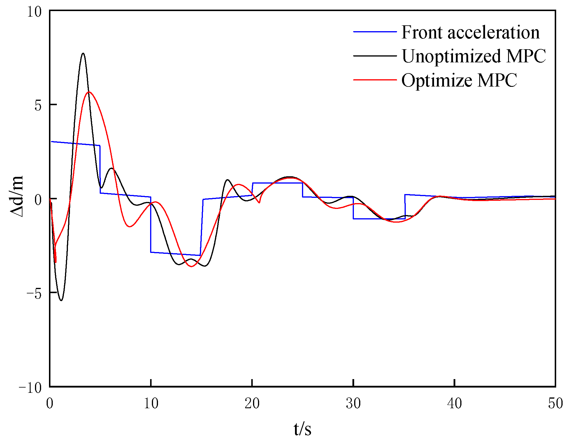
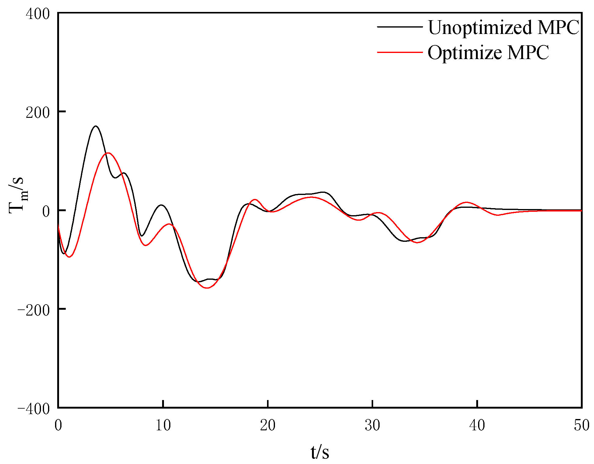
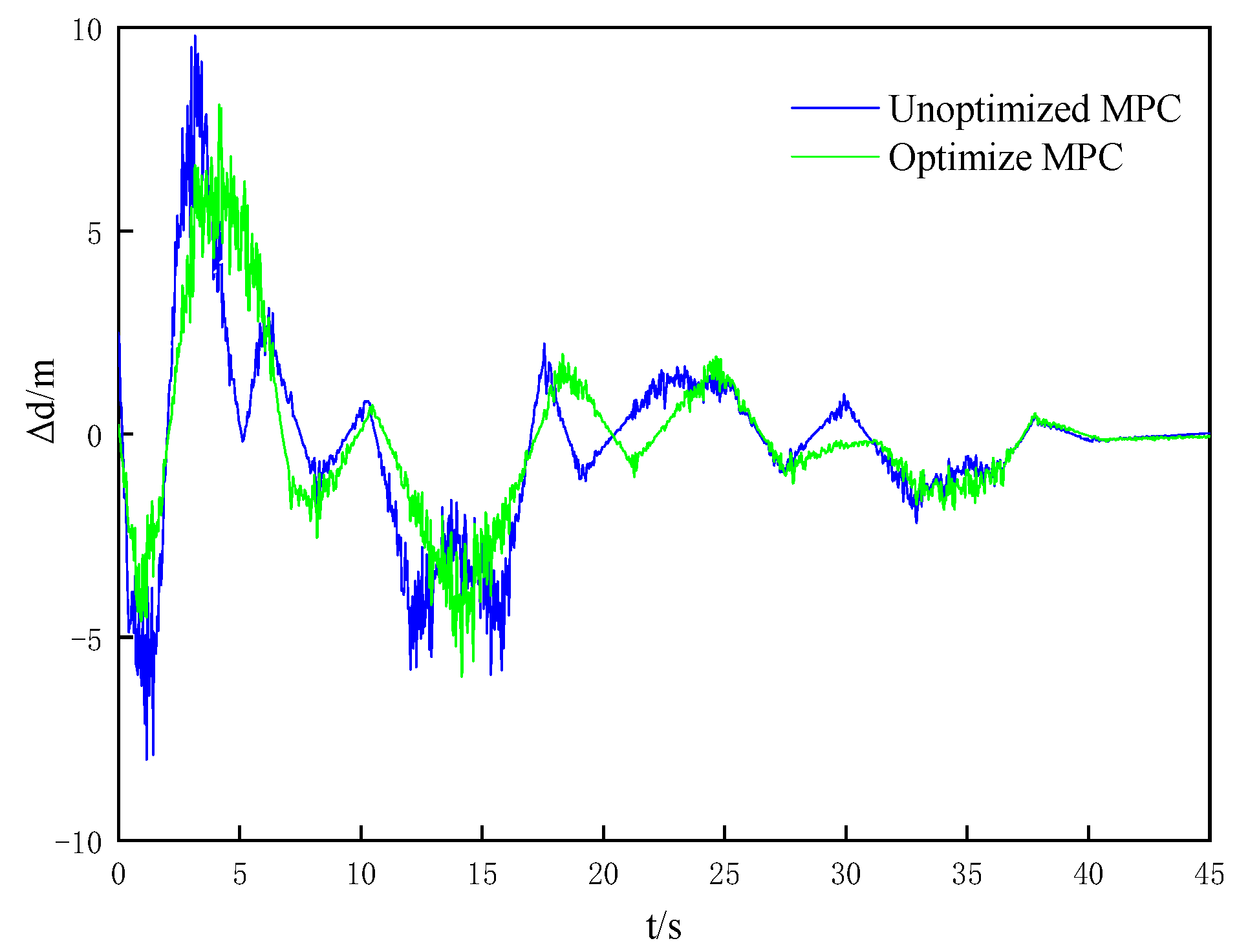
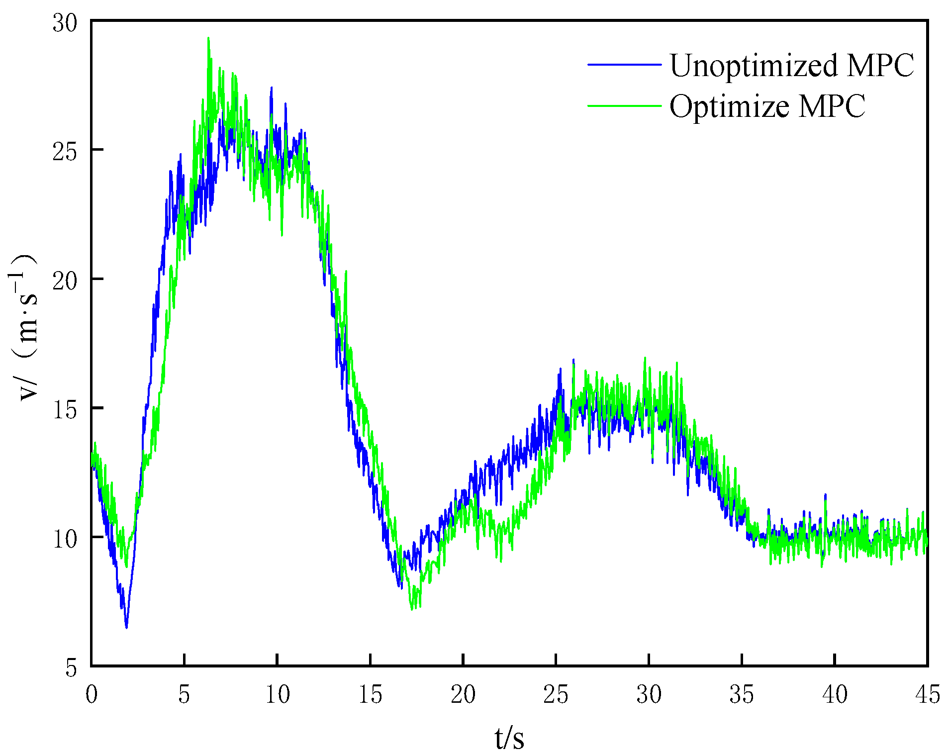
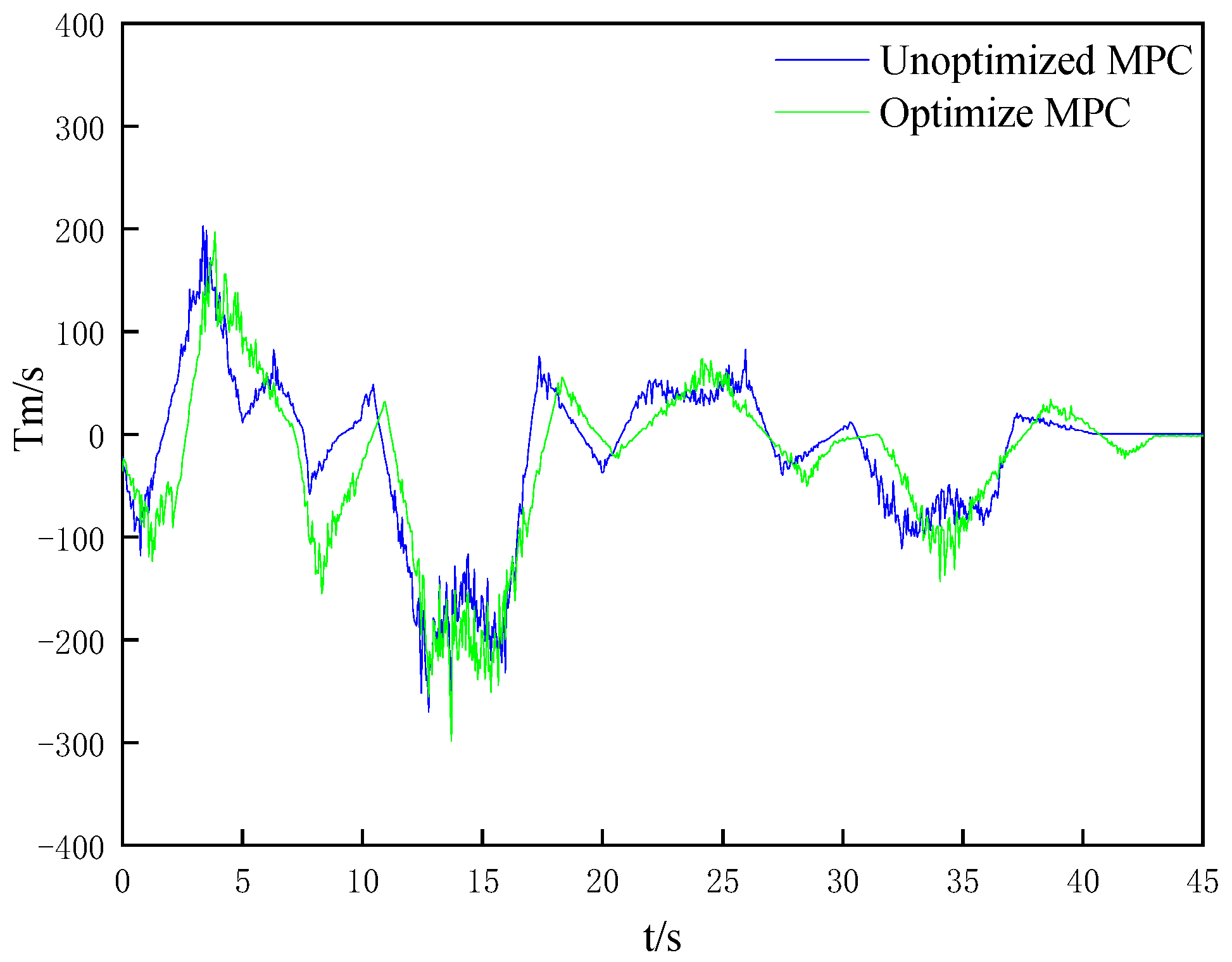
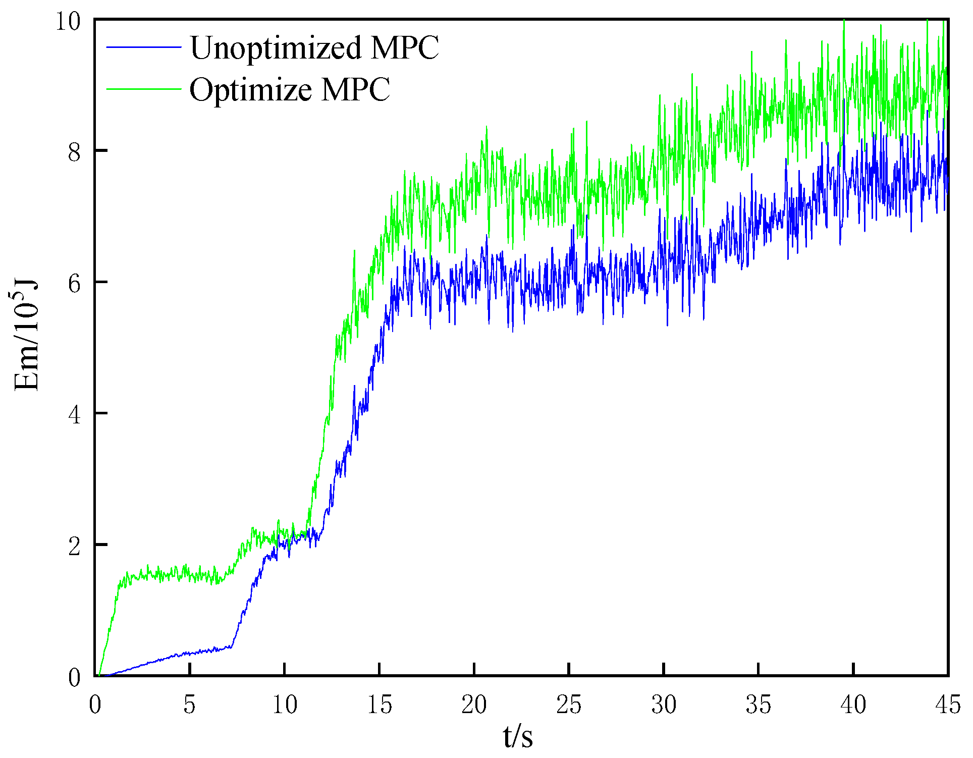
In the initial state, the speed of the front vehicle is 10 m·s−1, the speed of the rear vehicle is 15 m·s−1, the distance between the two vehicles is 30 m and the acceleration of the front vehicle changes according to a certain trajectory. The active collision avoidance control algorithm of MPC with energy recovery optimization and without energy recovery optimization is simulated and compared. The simulation results are shown in Figure 2, Figure 3, Figure 4, Figure 5 and Figure 6.
It can be seen from the simulation results that both methods can control the workshop distance and speed well while following of the front and rear vehicles. In the initial stage, due to the large speed deviation between the two vehicles, large distance between vehicles and the large algorithm adjustment, the system is not suitable for the front vehicle. However, when the speed of the two vehicles is close, the system will gradually stabilize, and the rear vehicle can keep up with the speed change of the front vehicle, but there is a certain lag. After the current vehicle enters the steady state, the workshop distance error and vehicle speed error finally converge to zero. In terms of acceleration, the speed reduction of the unoptimized MPC algorithm changes greatly, and the speed reduction of the optimized MPC algorithm changes little, which is mainly due to the good energy recovery effect of the regenerative braking system under medium-intensity braking.
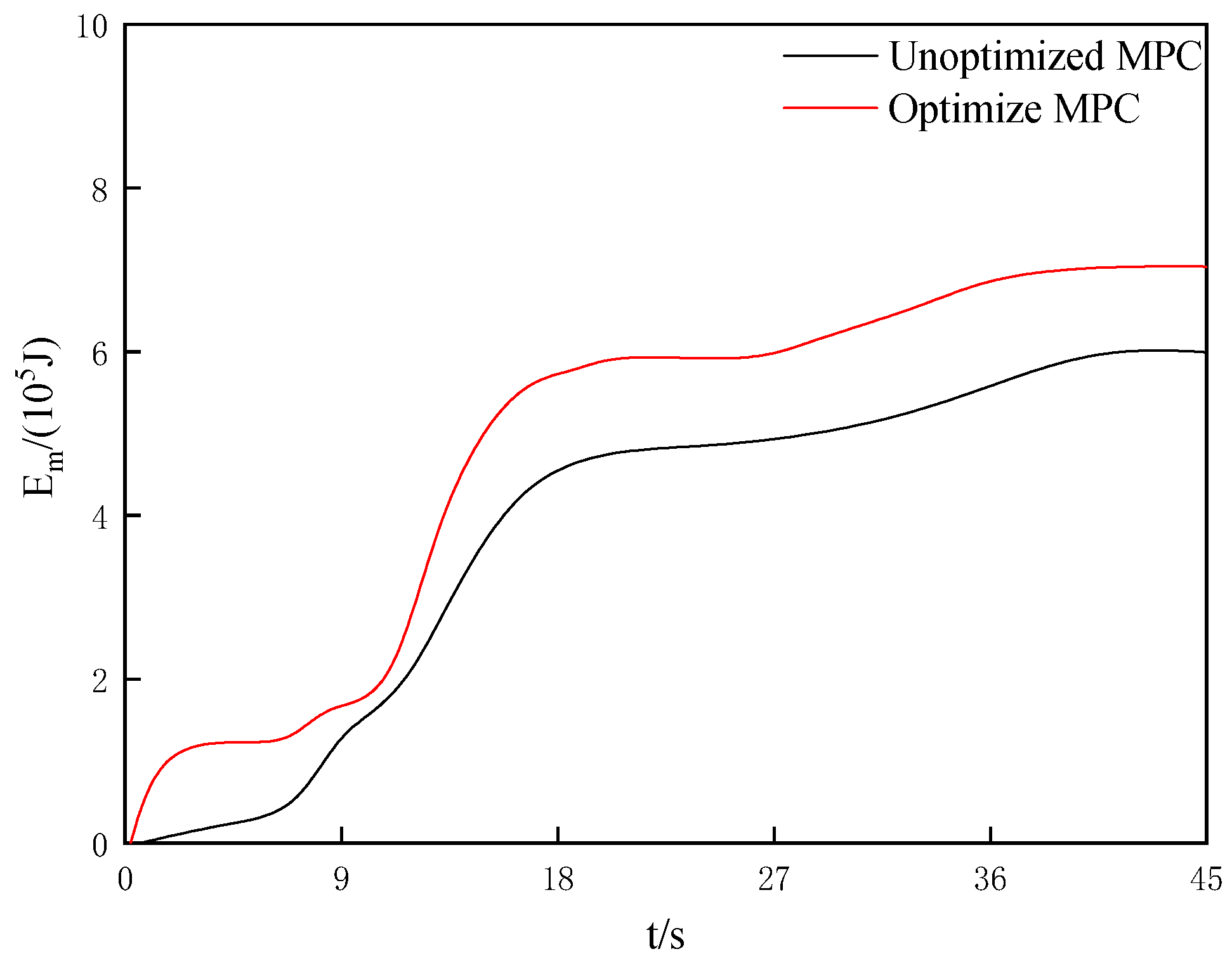
For the evaluation of the regenerative braking performance, the dynamic energy recovery rate can be used as the evaluation index. It is defined as the ratio of the energy recovered by the motor to the total energy during braking. The calculation is as follows:
η reg = j = 1 n t j _ 1 t j _ 2 T m n m 9.55 d t j = 1 n 1 2 m v j _ 0 2 1 2 m v j _ t 2
where the total braking time under the simulation condition is n , during the j th braking, and for the total braking n times, in the j th braking, v j _ ( ) is the initial braking end speed (m/s), v j _ t is the braking end speed (m/s), t j _ 1 is the initial braking end time(s) and t j _ 2 is the braking end time(s).
In the simulation process, the energy recovery rate of the unoptimized MPC algorithm is 32.2%. The energy recovery rate of the optimized MPC algorithm is 37.8%. The change of recovery energy is shown in Figure 6, and the total recovery energy of the unoptimized algorithm is 754.36 kJ. The energy recovered by the optimization algorithm was 890.2 kJ.

4. Analysis of Test Results

In order to further verify the effectiveness of the designed active braking system based on MPC active collision avoidance control algorithm, this section builds an experimental platform based on the smart car and conducts experimental studies on the active braking actuator and controller designed above.

4.1. Real Vehicle Experimental Platform

In this paper, an SUV is selected as the test vehicle, and the corresponding experimental platform is built on this test vehicle. The main parameters of the test vehicle are shown in Table 2.
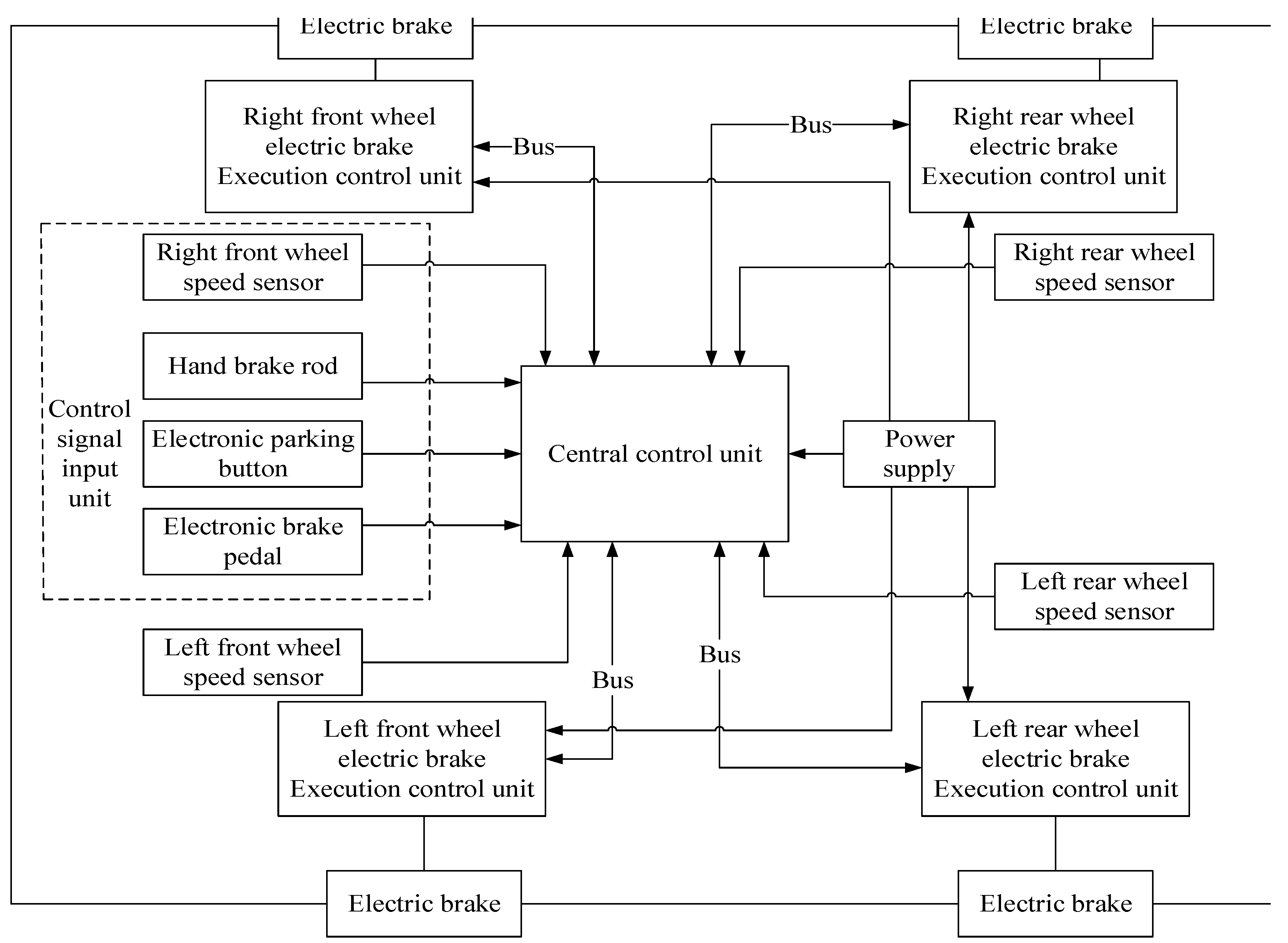
The experimental platform is divided into two parts: hardware and software. The software part depends on the DSPACE autobot control platform. The hardware part is arranged as shown in Figure 7. The hardware structure of the whole system is composed of a central controller and four sub-control drive units, and the CAN bus is used for information transmission.

4.2. Sensor

The main function of the sensor is to obtain various parameters in the process of vehicle operation, to lay the foundation for future experimental verification. Among them, the wheel speed sensor, the acceleration sensor and the pressure sensor are the most widely used sensors at present.

4.2.1. Wheel Speed Sensor

A new magnetoelectric speed sensor is used in this paper. It can accurately detect the wheel speed and track it. This sensor is installed on the gear ring of the wheel. When the wheel rotates, it will rotate with the rotation of the wheel, because it has a certain proportional relationship with the electronic signal, so the measured signal frequency can be used to calculate its speed.

4.2.2. Acceleration Sensor

Braking deceleration is an important indicator to measure the braking performance of the system, which needs to be obtained by accurate acceleration sensors. In this experiment, a nine-axis acceleration sensor is installed on the test platform of the active braking system.

4.2.3. Braking Pressure Sensor

The pressure sensor is installed on the brake pedal of the test vehicle, and the pressure signal can be used to judge whether the driver has a brake intervention. The test vehicle uses a diaphragm pressure sensor, model CEMPX4.

4.2.4. Actuator of Active Braking System

The actuator of the active braking system mainly consists of a drive motor, worm wheel, ball screw and brake caliper [32,33,34]. The ball screw is used to realize the non-self-locking mechanism, and the electromagnet is used to realize the self-locking pressure-retaining mechanism. The specific parameters are shown in Table 3.
The braking performance test results of the active collision avoidance braking system obtained in this test are shown in Figure 8, Figure 9, Figure 10, Figure 11 and Figure 12.
It is not difficult to see that the experimental results are basically the same as the simulation results. Both the non-optimized MPC algorithm and the optimized MPC algorithm can adapt well to the vehicle spacing and vehicle speed following the vehicle ahead. However, the experimental results are not ideal. Compared with the simulation results, the error is large. The factors that may lead to this difference are analyzed as follows: (1) Experimental data processing. There is a delay in reading sensor data, resulting in a larger braking time. (2) The simulation model has deviation. Since the mathematical models used in the simulation are simplified and theoretical models, there is a certain deviation from the test vehicle itself.

5. Conclusions

Based on MATLAB/Simulink and the Carsim simulation software platform, the vehicle model was built, and based on the MPC algorithm, a multi-objective active collision avoidance control algorithm considering safety and comfort was established. The optimization of the electric vehicle active collision avoidance control system for comfort optimization was studied by simulation and experimentation. The simulation results show that the active collision avoidance control system based on the MPC algorithm can follow the vehicle under different working conditions and ensure the safety and comfort in the process of following the vehicle while meeting the requirements of the active collision avoidance control system. The results show that the strategy meets the requirements of active collision avoidance tracking, safety and comfort. Compared with the unoptimized algorithm, the simulation energy recovery rate increases by 5.6%, and the contribution rate of test braking energy recovery increases by 5.4%.
In future research, the driving and braking process of pure electric vehicles can be coordinated and optimized by further analyzing the motor efficiency characteristics and using more intelligent algorithms, so as to improve the various performance of the system.

Author Contributions

Conceived and wrote the original draft preparation, N.L.; assisted in implementing the research content of the paper, provided critical comments, Y.L.; made improvements, T.Z.; wrote the original draft preparation, designed the content of the paper, Y.Y.; designed and researched the content of the paper, C.W.; editing and validation, X.W. All authors have read and agreed to the published version of the manuscript.

Funding

Natural Science Foundation of Shandong Province, No. ZR2022QE290.

Data Availability Statement

The study did not involve important data.

Conflicts of Interest

The authors declare no conflict of interest.

References

  1. Zhang, Z.; Wang, C.; Zhao, W.; Feng, J. Longitudinal and lateral collision avoidance control strategy for intelligent vehicles. J. Automob. Eng. 2022, 236, 09544070211024048. [Google Scholar] [CrossRef]
  2. Yuan, C.; Lv, S.; Shen, J.; Chen, L.; He, Y.; Weng, S. Research on emergency collision avoidance system of man-machine cooperative driving vehicles based on additional yaw moment control. IEEE Access 2022, 10, 51757–51770. [Google Scholar] [CrossRef]
  3. Li, H.; Li, Y.; Zheng, T.; Zhang, H. Emergency collision avoidance strategy for autonomous vehicles based on steering and differential braking. Res. Sq. 2022, 1, 10–18. [Google Scholar] [CrossRef]
  4. Han, W.; Zhu, Q.; Liu, Y.; Zhao, J.; Chen, Y. Reinforce learning-based collision avoidance in network assisted automated driving. Res. Sq. 2022, 1, 4–17. [Google Scholar]
  5. Kao, I.; Yian, Y.; Su, J.; Lai, Y.; Perng, J.; Hsieh, T.; Tsai, Y.; Hsieh, M. Design of sensor fusion driver assistance system for active pedestrian safety. arXiv 2022, arXiv:2201.09208. [Google Scholar]
  6. Hong, J.; Ma, F.; Xu, X.; Yang, J.; Zhang, H. A novel mechanical-electric-hydraulic power coupling electric vehicle considering different electrohydraulic distribution ratios. Energy Convers. Manag. 2021, 249, 114870. [Google Scholar] [CrossRef]
  7. Sun, C.; Zheng, S.; Ma, Y. An active safety control method of collision avoidance for intelligent connected vehicle based on driving risk perception. J. Intell. Manuf. 2021, 32, 1249–1269. [Google Scholar] [CrossRef]
  8. Cao, Y.; Wen, J.; Ma, L. Tracking and collision avoidance of virtual coupling train control system. Future Gener. Comput. Syst. 2021, 120, 76–90. [Google Scholar] [CrossRef]
  9. Du, L.; Ji, J.; Zhang, D.; Zheng, H.; Chen, W. A fuzzy drive strategy for an intelligent vehicle controller unit integrated with connected data. Machines 2021, 9, 215. [Google Scholar] [CrossRef]
  10. Feng, S.; Qian, Y.; Wang, Y. Collision avoidance method of autonomous vehicle based on improved artificial potential field algorithm. J. Automob. Eng. 2021, 235, 3416–3430. [Google Scholar] [CrossRef]
  11. Ahangarnejad, A.H.; Radmehr, A.; Ahmadian, M. A review of vehicle active safety control methods: From antilock brakes to semiautonomy. J. Vib. Control 2021, 27, 1683–1712. [Google Scholar] [CrossRef]
  12. Li, K.; Zhang, R.; Wang, H.; Yu, F. Multi-intelligent connected vehicle longitudinal collision avoidance control and exhaust emission evaluation based on parallel theory. Process Saf. Environ. Prot. 2021, 150, 259–268. [Google Scholar] [CrossRef]
  13. Mao, J.; Yang, L.; Hu, Y.; Liu, K.; Du, J. Research on vehicle adaptive cruise control method based on fuzzy model predictive control. Machines 2021, 9, 160. [Google Scholar] [CrossRef]
  14. Tian, G.; Fathollahi-Fard, A.; Ren, Y.; Li, Z.; Jiang, X. Multi-objective scheduling of priority-based rescue vehicles to extinguish forest fires using a multi-objective discrete gravitational search algorithm. Inf. Sci. 2022, 608, 578–589. [Google Scholar] [CrossRef]
  15. Narayanan, P.; Sengan, S.; Marimuthu, B.; Paulra, R.; Bhargava, C.; Sharma, P.; Kumar, K.; Dadheech, P. Analysis and design of fuzzy-based manoeuvring model for mid-vehicle collision avoidance system. J. Ambient. Intell. Humaniz. Comput. 2021, 12, 9909–9922. [Google Scholar] [CrossRef]
  16. Tian, G.; Zhang, C.; Fathollahi-Fard, A.; Li, Z.; Zhang, C.; Jiang, Z. An enhanced social engineering optimizer for solving an energy-efficient disassembly line balancing problem based on bucket brigads and cloud theory. IEEE Trans. Ind. Inform. 2022, 2–11. [Google Scholar] [CrossRef]
  17. Qin, J.X.; Deng, W.W.; He, R. Intelligent vehicle collision risk modeling and comprehensive evaluation method. In Proceedings of the 2019 3rd Conference on Vehicle Control and Intelligence (CVCI), Hefei, China, 21–22 September 2019; Volume 9, pp. 100–110. [Google Scholar]
  18. Yuan, W.; Yang, G.; Fu, R. Effect of driver inhibitory control on risk driving behavior. Automot. Eng. 2021, 43, 4132–4163. [Google Scholar]
  19. Tian, G.; Yuan, G.; Aleksandrov, A.; Zhang, T.; Li, Z.; Fathollahi-Fard, A.M.; Ivanov, M. Recycling of spent Lithium-ion batteries: A comprehensive review for identification of main challenges and future research trends. Sustain. Sustain. Energy Technol. Assess. 2022, 53, 102447. [Google Scholar] [CrossRef]
  20. Li, J. Study of Intelligent Vehicle Driving Control Switching and Evaluation Method Considering Driving Style; Jilin University: Jilin, China, 2021. [Google Scholar]
  21. Wang, Y.; Sun, W.; Lu, Y. Research on Application in Intelligent Vehicle Automatic Control System; IOP Publishing: Bristol, UK, 2021; Volume 1828, p. 012046. [Google Scholar]
  22. Xu, Y.; Chu, L.; Zhao, D. A novel adaptive cruise control strategy for electric vehicles based on a hierarchical framework. Machines 2021, 9, 263. [Google Scholar] [CrossRef]
  23. Deng, G.; Zhang, X.; Song, H. Design of car-following algorithms for cooperative adaptive cruise controlsyste. J. Chongqing Univ. Technol. 2019, 33, 32–37. [Google Scholar]
  24. Tian, G.; Ren, Y.; Feng, Y.; Zhou, M.; Zhang, H.; Tan, J. Modeling and planning for dual-objective selective disassembly using or graph and discrete artificial bee colony. IEEE Trans. Insdustrial Inform. 2018, 15, 2456–2468. [Google Scholar] [CrossRef]
  25. Liang, W.; Ahmac, E.; Khan, M.A.; Youn, I. Integration of active tilting control and full-wheel steering control system on vehicle lateral performance. Springer Link 2021, 22, 979–992. [Google Scholar] [CrossRef]
  26. Fu, Y.; Li, C.; Yu, F.R.; Luan, T.H.; Zhang, Y. A survey of driving safety with sensing, vehicular communications, and artificial intelligence-based collision avoidance. IEEE Trans. Intell. Transp. Syst. 2021, 23, 6142–6163. [Google Scholar] [CrossRef]
  27. Liu, Y.; Tan, J. Experimental study on solid SCR technology to reduce no emissions from diesel engines. IEEE Access 2020, 8, 151106–151115. [Google Scholar] [CrossRef]
  28. Wang, Y.; Yin, G.; Li, Y.; Ullah, S.; Zhuang, W.; Wang, J.; Zhang, N.; Geng, K. Self-learning control for coordinated collision avoidance of automated vehicles. J. Automob. Eng. 2021, 235, 1149–1163. [Google Scholar] [CrossRef]
  29. Ke, H.; Liu, H.; Tian, G. An uncertain random programming model for project scheduling problem. Int. J. Intell. Syst. 2015, 30, 66–79. [Google Scholar] [CrossRef]
  30. Tian, G.; Chu, J.; Liu, Y.; Ke, H.; Zhao, X.; Xu, G. Expected energy analysis for industrial process planning problem with fuzzy time parameters. Conputers Chem. Eng. 2011, 35, 2905–2912. [Google Scholar] [CrossRef]
  31. Hang, P.; Xia, X.; Chen, G.; Chen, X. Active safety control of automated electric vehicles at driving limits: A tube-based MPC approach. IEEE Trans. Transp. Electrif. 2021, 8, 1338–1349. [Google Scholar] [CrossRef]
  32. Li, N.; Liu, Y.; Tan, S. Experimental research on braking feedback and taxiing feedback system of new energy vehicles. Appl. Sci. 2021, 11, 11093. [Google Scholar] [CrossRef]
  33. Li, N.; Liu, Y.; Zhang, J. Research on energy consumption evaluation of electric vehicles for thermal comfort. Environ. Sci. Pollut. Res. 2022, 1–13. [Google Scholar] [CrossRef]
  34. Li, N.; He, C.; Zhang, J. Research on the Influence of Air Conditioning Energy Consumption on Brake Energy Recovery Contribution Rate Based on Operating Conditions; IOP Conference Series: Earth and Environmental Science; IOP Publishing: Bristol, UK, 2021; Volume 638, p. 012018. [Google Scholar]
Figure 1. Overall system structure of active collision avoidance control.
Processes 11 00485 g001
Figure 2. Simulation results of vehicle spacing.
Processes 11 00485 g002
Figure 3. Simulation results of vehicle speed.
Processes 11 00485 g003
Figure 4. Acceleration simulation results.
Processes 11 00485 g004
Figure 5. Simulation results of motor torque.
Processes 11 00485 g005
Figure 6. Simulation results of energy recovery.
Processes 11 00485 g006
Figure 7. Hardware configuration diagram of the test platform.
Processes 11 00485 g007
Figure 8. The test results of vehicle spacing.
Processes 11 00485 g008
Figure 9. Vehicle speed test results.
Processes 11 00485 g009
Figure 10. Acceleration test results.
Processes 11 00485 g010
Figure 11. Test results of motor torque.
Processes 11 00485 g011
Figure 12. Energy recovery test results.
Processes 11 00485 g012
Table 1. Pure electric vehicle’s whole vehicle parameters.
Serial NumberParameterSymbolFigureUnit
1Wheel rolling radiusr0.275m
2Wheel rotation inertiaIW1kg/m2
3Total mass of the carm1360kg
4WheelbaseL2.33m
5The distance from the
front axle to thea1.0657m
center of mass
6The distance from the
rear axle to the centerb1.2643m
of mass
7Centroid heighth0.627m
8Drag coefficientCD<0.32
9Reducer gear ratioi3.5
10Windward areaA2.142m2
Table 2. Main parameters of test vehicle.
NameParameter
L × W × H (mm)4600 × 1780 × 1445
Wheelbase (mm)2700
Tread front (mm)1555
Tread rear (mm)1568
Complete vehicle quality (kg)1235
Tire size195/65 R15
Full speed (km/h)190
Table 3. Main parameters of implementing agencies.
NameParameter
Motor back EMF coefficient0.104
Worm-gear drive ratio25
Mechanical efficiency of worm gear0.95
Ball screw guide (m)0.008
Mechanical efficiency of ball screw0.95
Braking coefficient0.8
Disclaimer/Publisher’s Note: The statements, opinions and data contained in all publications are solely those of the individual author(s) and contributor(s) and not of MDPI and/or the editor(s). MDPI and/or the editor(s) disclaim responsibility for any injury to people or property resulting from any ideas, methods, instructions or products referred to in the content.