Review

A Review on Rotary Generators of Hydrodynamic Cavitation for Wastewater Treatment and Enhancement of Anaerobic Digestion Process

1
Faculty of Civil and Geodetic Engineering, University of Ljubljana, Jamova Cesta 2, SI-1000 Ljubljana, Slovenia
2
Faculty of Mechanical Engineering, University of Ljubljana, Aškerčeva Cesta 6, SI-1000 Ljubljana, Slovenia
3
National Institute of Chemistry, Hajdrihova 19, SI-1000 Ljubljana, Slovenia
*
Author to whom correspondence should be addressed.
Processes 2023, 11(2), 514; https://doi.org/10.3390/pr11020514
Submission received: 19 January 2023 / Revised: 1 February 2023 / Accepted: 6 February 2023 / Published: 8 February 2023
(This article belongs to the Section Environmental and Green Processes)

Abstract

:
The issue of ever-increasing amounts of waste activated sludge (WAS) produced from biological wastewater treatment plants (WWTPs) is pointed out. WAS can be effectively reduced in the anaerobic digestion (AD) process, where methanogens break down organic matter and simultaneously produce biogas in the absence of oxygen, mainly methane and CO2. Biomethane can then be effectively used in gas turbines to produce electricity and power a part of WWTPs. Hydrodynamic cavitation (HC) has been identified as a potential technique that can improve the AD process and enhance biogas yield. Rotary generators of hydrodynamic cavitation (RGHCs) that have gained considerable popularity due to their promising results and scalability are presented. Operation, their underlying mechanisms, parameters for performance evaluation, and their division based on geometry of cavitation generation units (CGUs) are presented. Their current use in the field of wastewater treatment is presented, with the focus on WAS pre/treatment. In addition, comparison of achieved results with RGHCs relevant to the enhancement of AD process is presented.

Graphical Abstract

1. Introduction

An adequate amount of drinking water is crucial for the development of modern human society. However, due to the significant increase in human population in recent decades, freshwater resources are becoming increasingly scarce and at the same time the amount of produced wastewater is increasing [1]. This wastewater must be properly and carefully treated before it is discharged back into the environment as it can pose a great risk to the environment and human health. In most cases, wastewater is treated by utilizing the biological activated sludge process, which produces significant amounts of excess sludge. In Europe alone, several million tons of sludge is generated each year [2]. Excess sludge can be usefully exploited in the anaerobic digestion (AD) process for biomethane production. The amount of produced biogas can be increased by various pretreatment processes.
It has been reported that conventional wastewater treatment methods are often unable to remove complex organic contaminants [3] and sometimes even unable to completely degrade contaminants in the sludge, thus posing an issue in digested sludge quality. As new complex organic chemicals are found in wastewater every year [4,5], new treatment methods are of academic and industrial interest [6]. One of the recognized promising unconventional techniques is hydrodynamic cavitation (HC), which was exclusively associated with engineering problems, such as noise, vibration and cavitation erosion (indicators of reduced machine efficiency). However, in the last decade HC has been widely recognized as a possible wastewater treatment method due to its effective destruction of complex organic chemicals, nonchemical nature, good compatibility with other advanced oxidation processes, ease of operation, excellent generation of the required intensities of cavitation conditions, possible pilot scale application, good experimental results and economic aspects [6,7,8,9,10,11]. An increasing number of published documents on the keywords “hydrodynamic cavitation” and “wastewater treatment,” and “cavitation and wastewater treatment” can be seen in Figure 1.
Based on the type of pollution, wastewater can be categorized into four categories: domestic, industrial, infiltration/inflow and stormwater [12]. However, some authors categorize wastewater also as domestic, industrial, and agricultural [13]. Domestic wastewater can be further divided into gray water and black water. Gray water refers to wastewater generated by households, public institutions, schools, bars, hotels, gyms, hospitals etc. (generally, from streams without fecal contamination). This includes sources from kitchen sinks, baths, showers, washing machines and dishwashers. Black water refers to wastewater from bathrooms and toilets (from streams containing feces and urine) [13,14].
Characteristics of wastewater are mainly dependent on source of pollution, physical, chemical, biological and other properties, such as suspended solids (SS), organic matter, nutrients, and pathogenic microorganisms [13]. Physical characteristics of wastewater are color, odor, content of total solids, temperature, flow rate and turbidity. Chemical characteristics include parameters such as chemical oxygen demand (COD), soluble chemical oxygen demand (sCOD), particulate chemical oxygen demand (PCOD), total organic carbon (TOC), nitrogen, Kjeldahl nitrogen, phosphorus, chlorides, sulfates, alkalinity, pH, heavy metals, trace elements and certain pollutants. Biological characteristics include biochemical oxygen demand (BOD), oxygen required for nitrification, and microbial population.
Wastewater can be treated in four types of WWTPs: sewage treatment plants, effluent treatment plants, activated sludge plants and common and combined effluent treatment plants. Appropriate WWTP is selected based on the type of wastewater and the extent of contamination. Generally speaking, WWTP is an industrial facility in which a combination of mechanical, physical, chemical and biological processes is used to achieve the removal of constituents from the influent [15]. These processes are grouped together to provide what is known as preliminary, primary, secondary, tertiary, and advanced treatment. “Primary” refers to applications of physical processes, “secondary” refers to chemical and biological processes, and “tertiary” refers to combinations of all three [12]. Permissible effluent values are predetermined by approved directives, guidelines, regulations and/or standards. For the protection of public and environmental health, adequate reduction in biodegradable organic substances, reduction of nutrient concentration, elimination of pathogens, recycling, reuse of water and in some cases even disinfection must be achieved [12,14].
In the following chapters, we review the stages of the anaerobic digestion process, main principles of advanced oxidation processes, fundamentals of cavitation phenomena with the emphasis on hydrodynamic cavitation, regularly used parameters for describing RGHC operating conditions and performance, and different types of RGHC.

2. Anaerobic Digestion Process

Sludge produced in WWTPs is highly septic and therefore needs to be stabilized for its safe utilization and disposal. The standard technique used for sludge stabilization is anaerobic digestion, a biological process in which microorganisms break down organic matter in the absence of oxygen. This results in the generation of biogas, which mainly consists of carbon dioxide and methane. Biogas production is driven by complex microbial communities of bacteria, archaea, protozoa and fungi, all capable of adapting to environmental conditions of anaerobic digestion [16]. The process consists of four stages: hydrolysis, acidogenesis, acetogenesis and methanogenesis. Efficient biogas production is dependent on a uniform decomposition rate of all four phases [17]. Riviere et al. (2009) [18] defined the most abundant microorganism groups in seven different full-scale wastewater treatment plant anaerobic digesters. The main phylogenetic groups for Euryachaeaota are Methanosarcinales, Methanomicrobiales and Methanobacteriales. Laiq et al. in 2019 added Methanococcales, Methanosarcinales and Methanopyrales [19]. For the bacteria domain, the main groups are Chloroflexi, Proteobacteria, Bacteroidetes, Fibirbacter, Spirochaetes, Thermotogae and Firmicutes [18,19].
WWS can also be used as a co-substrate in anaerobic co-digestion with solid waste from various sources (industry, municipality, agriculture). Distinct types of solid wastes and their methane potentials are given by [20] in online methane yield database (http://methane.fe.uni-lj.si/ (1 February 2023). Co-digestion with wastewater sludge can enhance biogas production by adjusting, for example, pH, moisture, the C/N ratio, and nutrient availability. However, process stability must be maintained by proper C/N ratio, substrate ratio and operating conditions [21,22,23,24].

2.1. Hydrolysis

In hydrolysis, polymers are broken down into simpler and process-soluble monomers (monosaccharides, amino acids, and lipids) [25]. The rate of hydrolysis strongly depends on the substrate used. Carbohydrates are broken down in a matter of hours, while fats and proteins are broken down in a matter of days. Complex polymers, such as lignocellulose and lignin, cannot be completely degraded due to their complex composition and should be processed in pretreatment operations [26]. Hydrolysis is a rate-limiting and critical step in anaerobic digestion and can affect the following steps if not monitored closely.

2.2. Acidogenesis

In the acidogenesis process, fermentation of soluble monomers to short-chain fatty acids (acetic, propanoic, butanoic), alcohols, CO2, H2, H2S, NH3 and NOx takes place. The majority of products are short-chain fatty acids. At this stage, optional and strict anaerobes predominate [26]. Among all formed compounds, the most important is acetate, which is the main substrate for methanogenic archaea and methane synthesis [25]. Bacterial genera that occur at the stage of acidogenesis also occur at the hydrolysis stage [26].

2.3. Acetogenesis

In acetogenesis, products of acidogenesis are anaerobically oxidized into H2, CO2, acetate and compounds with one carbon atom [26]. Acetogenic bacteria can only survive in a syntrophic relationship with methanogenic archaea [27]. Methanogenic archaea constantly consume hydrogen that is formed during the oxidation of butyrate and propionate, thus providing low partial pressure of hydrogen, which is a prerequisite for the normal operation and growth of acetogenic bacteria. If the partial pressure of hydrogen is low, most of the acetate is synthesized by acetogenic bacteria. In contrast, if partial pressure of the hydrogen is high, propionate and butyrate are not consumed, leading to reduced methane production [26].

2.4. Methanogenesis

Methanogenesis is performed by methanogenic archaea. They grow in clusters and are resistant to high salt concentrations [25]. In methanogenesis, we distinguish two mechanisms of methane formation: decomposition of acetic acid (acetoclastic methanogenesis) and reduction of carbon dioxide (hydrogenotrophic methanogenesis) [26,28]. In the absence of hydrogen, methane and carbon dioxide are formed during the decomposition of acetic acid. The methyl group of acetic acid is reduced into methane, while the carboxyl group is oxidized to carbon dioxide. When hydrogen is available, methane is formed from the reduction of carbon dioxide [26]. About two-thirds of methane is formed from acetate and one-third from H2 and CO2 [28]. Because CO2 in an anaerobic reactor is always abundant, its reduction to methane is not a limiting factor of the process. However, as acetate and hydrogen are also a preferred source of energy for sulfate-reducing bacteria (SRB), they compete with methanogens for substrate and electron acceptor [29]. Methanogens thrive the most at temperatures from 35 to 42 °C, while SRB thrive the most at temperatures from 28 to 32 °C [30,31]. Consequently, at lower temperatures and high sulfate concentrations, methanogens are outcompeted and the electron flow is diverted towards sulfate reduction. Furthermore, the more acidic the pH, the better SRB thrive, and more hydrogen sulfide (H2S) is generated [32]. In this case, biocide compounds can be added to reactors to inhibit SBR microbial activity.

2.5. Improving the Anaerobic Digestion Process

Anaerobic digestion is a complex biochemical process dependent on many physicochemical and biological factors. These factors include pH, hydraulic retention time (HRT), organic loading rate (OLR), C/N/P/S ratio, alkalinity, volatile fatty acids (VFAs), trace elements, temperature, mixing in the reactors, type of substrate being used, specific surface of substrates, particle size, redox potential, etc. [26,33] The rate-limiting step of anaerobic sludge stabilization is biological cell lysis—the hydrolysis step [34,35]. Sludge anaerobic degradability can be enhanced with various pretreatment techniques such as mechanical, biological, chemical, and thermal. In general, mechanical and biological treatment methods solely improve degradation rate while thermal hydrolysis and oxidation improve both rate and its extent. Nonetheless, since application of mechanical processes increases the rate of hydrolysis and with that anaerobic biodegradability of substrates [36] at relatively low energy consumption, sludge pretreatment is recommended [37]. The main objective of sludge pretreatment is breakage of cell walls, which results in a release of intracellular organic compounds into the aqueous phase. Consequently, large COD release is achieved, leading to more efficient disintegration. Some reported benefits of waste activated sludge treated by cavitation are the reduction in sludge digester volume, decrease in retention hydraulic time in digestors and higher degree of volatile solid degradation [35]. Several authors reported that pretreatment of sludge before the anaerobic digestion process also increases the production of biogas [35,38,39,40,41,42]. According to [26], optimal conditions for anaerobic digestion process are different for distinct stages of the process. The goal is to ensure the optimal conditions for microorganisms involved in the degradation of substrates and production of methane. For example, optimal pH value for the hydrolysis/acidogenesis step is between 5.2 and 6.3, while for methanogenesis it is between 6.7 and 7.5. Further, the optimal mesophilic temperature range for the first stages is between 25 °C and 35 °C, while methanogen growth is optimal between 32 °C and 42 °C. In thermophilic range, temperatures are between 50 °C and 58 °C. However, temperature changes under thermophilic conditions that vary more than ±2 °C/day are not recommended, due to decrease in methanogen activity [35]. Macronutrients such as C, N, P and S should be present in sufficient amounts [43]. Their optimum C:N:P:S ratio is between 500:15:5:3 and 600:15:5:3 for the hydrolysis/acidogenesis phase and methanogenesis, respectively [26]. Optimum ratio C/N is between 20 and 35 [44]. Organic loading rate optimum is governed by substrate type and can be monitored by VOA/TIC ratio to avoid overloading and consequently accumulation and/or inhibition of VFA. Methane production during higher OLR is possible if sufficient alkalinity is provided [16,44]. Performance and stability of anaerobic digesters is also dependent on the trace element (TE) concentrations and availability. TEs play a significant role in the functioning of enzymes. Important TEs are iron (Fe), nickel (Ni), cobalt (Co), tungsten (W), molybdenum (Mo) and zinc (Zi) [26,45].

3. Advanced Oxidation Process

In the last decade, advanced oxidation processes (AOPs) have been of great interest in academic and industrial field due to their high effectiveness in wastewater purification and pathogen elimination [46,47]. AOPs include several different methods such as ozonation, photocatalysis, electrochemical oxidation, cavitation, UV, Fenton and Fenton-like processes and other hybrid processes [42,48,49]. The governing principle of AOPs is the utilization of highly oxidizing radicals, mainly hydroxyl (•OH) and hydrogen (•H), for nonselective degradation of pollutants such as refractory organic matters, traceable organic contaminants, and certain inorganic pollutants. As shown in Equations (1)–(5), these radicals can later recombine to form H2 and/or hydrogen peroxide (H2O2), which is commonly used as a strong oxidizer in many different water treatment processes [50].
H2O → •OH + •H,
•OH + •H → H2O,
•H + O2 → HO2•,
2OH• → H2O2,
2HO2• → H2O2 + O2
Compared to other oxidizing agents, hydroxyl radicals are widely accepted due to their high redox potential, i.e., 2.8 eV [49]. Moreover, their presence even further enhances chemical reactions, and with that, microorganism removal. Mechanisms of in situ radical formation, attack efficiency and degradation depend on several process parameters, such as water quality, quantity and type of chemicals added, chosen technique and used catalysts. In hybrid processes, pretreatment with HC is expected to substantially reduce chemical consumption. Additionally, it was shown that HC in combination with other AOPs can significantly increase intensification of industrial wastewater treatment process [51]. Combination of HC + Fenton + oxygen resulted in 63% COD removal, while with HC alone, only 6.3% was achieved. An orifice plate at 70 L operating capacity was used for the experiment. This section may be divided by subheadings. It should provide a concise and precise description of the experimental results, their interpretation, and the experimental conclusions that can be drawn.

4. Cavitation

Cavitation was first mentioned by Leonhard Euler in 1754, long before its first observation on the steamship Turbinia in 1897 [52,53]. In the past, cavitation was solely associated with engineering problems, such as noise, vibration and cavitation erosion, all indicators of decreased machine efficiency. Ever since, cavitation has been highly researched. By definition, cavitation is a type of vaporization, driven by a pressure decrease at constant temperature, Figure 2. This rapid phase change from liquid to gaseous state may occur when the fluid’s initial temperature is anywhere between the triple-point temperature and the critical temperature and the pressure at that temperature is initially greater than the vaporization pressure. If these conditions are meet, cavitation occurs when the local static pressure is decreased below the vapor pressure threshold. For instance, the evaporation pressure for water at 20 °C is 2.3388 kPa. Therefore, cavitation will take place if the water pressure is decreased to less than 2.3388 kPa. This results in formation, growth, and implosive collapse of microbubbles in a matter of milliseconds [6,54]. How bubble radius changes with time is presented in Figure 3.
Cavitation is most likely to occur when an adequate number of nucleation sites of sufficient size are present in the liquid. There are two possible types of nucleation, homogeneous and heterogeneous. In homogeneous nucleation, cavitation occurs due to thermal motions within the liquid, thus forming temporary microscopic voids that constitute necessary nuclei. On the other hand, in heterogeneous nucleation, major weaknesses usually occur at the boundary between the liquid and solid wall or between the liquid and small suspended particles [55]. Very small particles or microbubbles present as contaminants can pose as potential nucleation sites. Micron-sized particles were first proposed as cavitation nuclei in [56].
Figure 3. Formation, growth and collapse of the cavitation bubble. Adapted from Ref. [57].
Processes 11 00514 g003
In general, bubble collapse can be characterized as spherical or asymmetrical. In bulk media, bubbles are expected to collapse spherically. However, if cavitation occurs near the wall or a free surface, cavitation bubbles will collapse asymmetrically, forming microjets with velocities greater than 100 m/s [55,58,59,60,61], consequently posing a high risk of cavitation erosion [53]. HC jets are known to be very effective in reducing the concentration of Gram-negative E. coli, Klebsiella pneumoniae, Pseudomonas syringae and Pseudomonas aeruginosa and Gram-positive Bacillus subtilis [62]. The last phase of bubble collapse in close proximity to the solid surface can be described by two consecutive events: microjet and spherical microbubble collapse [61], schematically shown in Figure 4. Individual stages of the collapse are explained in more detail in Table 1.
Collapse of a single cavitation bubble is only 2–3 μs long [61] At the end of collapse, when walls of the cavitation bubble finally collide with each other, large magnitudes of energy are released. High-intensity shock waves that travel at supersonic speed of water (~6000 km/h) occur in the liquid. Local pressures exerted on a rigid spherical particle can surpass values of 1 GPa, and local temperatures can reach a few thousand Kelvins [64]. Ref. [65] reports that temperature inside the bubble can reach up to 5200 K. This results in dissociation of trapped vapor in the cavitating bubbles, hence generating additional free radicals.
These high pressures and temperatures of imploding gas bubbles promote even further the dissociation of water molecules into •OH and •H radicals. Reactions involving free radicals can occur within the collapsing bubble, at the interface of the bubble, and in the surrounding liquid. In some cases, faster degradation rate can occur at the cavity interface rather than in the liquid bulk, as radical concentration at the cavity interface can in some cases be higher [66]. Efficient generation of radicals plays a key role in the oxidation process of pollutant molecules. The probability of a cell coming into contact with the collapsing cavity is greater at higher cell concentrations. Therefore, at lower discharge pressures, cell concentration is one of the defining parameters of cell disruption [67].
In general, cavitation phenomena comprise three main effects: physical, thermal and chemical. Physical effects contribute to particle disintegration and lysis of microorganisms on account of generated shock waves, shear forces and microjets. Second, the thermal effect is responsible for the formation of local hot spots with heat transfer rates of 1010 K/s [68]. In the sludge treatment process, thermal effects also enhance cell lysis and destruction of cell walls. Consequently, sludge viscosity is reduced [69] and dewaterability of sludge can be improved. Third, a chemical effect occurs that is responsible for generating highly reactive hydroxyl radicals and other reactive species responsible for the oxidation of organic pollutants. Combination of these three effects can be utilized for the destruction of microbial cells [6,54,70,71] and sludge treatment [38,41,68,72].

4.1. Types of Cavitation

According to means of generation, cavitation can be categorized into four types: acoustic, hydrodynamic, optic, and particle cavitation [52]. Since the main purpose of this paper is to review scientific research in the field of HC for the improvement of anaerobic digestion process, the other three types will not be discussed in much detail.
Acoustic cavitation is a result of pressure variations in liquid that are generated by sound waves usually in the range of 16 kHz–100 MHz. The chemical changes occurring due to sound induced cavitation are known as sonochemistry [7,52]. It is widely accepted that mechanisms of bubble collapse in acoustic and hydrodynamic cavitation are very similar [73]. Optic cavitation is achieved by rupturing liquid with photons, usually with a high-intensity light or laser, while particle cavitation is achieved by rupturing liquid with any other of particle type, such as protons.

4.2. Hydrodynamic Cavitation

When liquid passes through a constriction such as an orifice plate or Venturi, the kinetic energy of the liquid increases at the expense of static pressure reduction. If the change in system geometry results in a velocity increase large enough so that the local static pressure of liquid is reduced to or below the vapor pressure, small bubbles or vapor cavities are formed in the medium. Further downstream in the divergent section, where pressure finally recovers, a collapse of cavities takes place. Intensity of cavitation is dependent on the intensity of turbulence [74]. In RGHCs where cavitation is mainly generated due to an opposite movement of two shear layers, the term “shear-induced hydrodynamic cavitation” was established.

4.3. Use of HC in Different Fields

Hydrodynamic cavitation has been widely employed in many different fields, including cell disruption [67,75], sludge treatment [68,72,76,77], water treatment [78], wastewater treatment [79,80], oxidation of organic compounds [81], preparation of aqueous detergent solutions [82], food and water processing [83], free fatty acid reduction in crude palm oil [84,85], disinfection [85,86,87,88,89,90], elimination of pathogenic bacteria [91,92], inactivation of pathogens in milk [93], biofuel production [94], intensification of biogas production [95], degradation of textile dyes [71,96,97,98], and removal of pharmaceuticals [99].

4.4. Evaluation of Cavitation Conditions and Performance

A function describing the spherical collapse of a single cavitation bubble was first proposed by Rayleigh in 1917. This equation was then expanded by Plesset in 1949 with the introduction of surface tension effects. The later equation is known as the Rayleigh–Plesset Equation (6), which originates from the Navier–Stokes equations (NSEs). The NSEs are a special form of continuity equation that describe the movement of a viscous incompressible fluid by relating velocity, pressure, temperature, and density. They are derived from the basic principles of conservation of mass, momentum, and energy. It is assumed that the fluid is a continuous substance and that field variables of interest are at least weakly differentiable. By employing NSEs and considering spherical symmetry, the motion of a single spherical cavitation bubble in a varying external pressure field can be described as follows [100]:
R d 2 R d t 2 + 3 2 ( d R d t ) 2 + 4   ν L R d R d t + 2   γ ρ L R + Δ p ( t ) ρ L = 0
Here, d is used to indicate partial derivatives, t is time, ρL is the density of the surrounding liquid, R(t) is bubble radius, νL kinematic viscosity of the surrounding liquid, γ surface tension of the bubble–liquid interface, and ∆p(t) pressure within the bubble.
However, because we are typically more interested in the magnitude and intensity of the phenomena as a whole, solving differential equations becomes very time-consuming and computationally expensive. In these circumstances, simple dimensionless equations are preferable. The most fundamental nondimensional parameter for evaluating cavitation potential is cavitation number σ, calculated by the following equation:
σ = p r p v ρ v 2 2
where pr is the reference pressure, pv vapor pressure, ρ density of the fluid, and v velocity of the fluid. Cavitation number is used to describe cavitation conditions at which a certain device operates. Every flow, cavitating or not, can be attributed a cavitation number. Generally speaking, σ relates flow conditions with cavitation intensity. The cavitation number at which the inception of cavitation occurs is known as the cavitation inception number σi. Under ideal conditions, cavitation inception typically appears at σi = 1. As the value decreases below 1, density of generated cavities and cavitational effects are increased. In general, the lower the cavitation number, the more cavities and the greater the collapse intensity. However, when the density of cavities is so large that cavities start to coalesce with each other, a cavity cloud is formed and the energy released from numerous collapses is therefore absorbed by the neighboring cavities. This phenomenon is called choked cavitation [87], and can be expressed by the so-called chocked flow cavitation number σc, first proposed in the work of [101]. To get the maximum cavitation effect, the cavitation device must be operated between cavitation inception and choked cavitation operating point [80]. Šarc et al. [102] showed that using cavitation number as the only parameter for describing cavitating conditions is insufficient since the value depends on several different parameters such as geometry, type of fluid, fluid temperature and velocity of the fluid. Therefore, accurate description of cavitating conditions must be provided.
Cavitational yield (CY) is a parameter used for characterization of cavitational reactors. It is defined as the ratio of the observed cavitational effect to the supplied power density of the system [80,103,104,105].
CY = c a v i t a t i o n a l   e f f e c t p o w e r   d e n s i t y
The effect of HC in wastewater treatment processes is usually expressed in terms of COD reduction (CR):
CR = COD 0 COD cav COD 0 × 100
where COD0 is initial chemical oxygen demand and CODcav chemical oxygen demand of sludge treated with cavitation.
Regarding biological performance of the WAS treatment process, HC efficiency is usually determined by measuring WAS solubilization improvement in terms of sCOD. Based on the good correlation between biogas production and disintegration degree (DD), cavitation generator performance can be evaluated with the following equation:
DD = sCOD cav sCOD 0 TCOD sCOD 0 × 100
where sCODcav is the soluble chemical oxygen demand of sludge treated with cavitation, sCOD0 soluble chemical oxygen demand of untreated sludge and COD initial total chemical oxygen demand. In some cases, performance can also be expressed as specific energy of sludge solubilization:
SESS = P   ·   t V · ( sCOD cav sCOD 0 )
where P is input power, t treatment time, and V volume of treated sludge.
Regarding disinfection or in general constituent degradation, removal efficiency is expressed as extent of degradation (ED), calculated with the following equation:
ED = C 0 C C 0 × 100
where C0 is initial pollutant concentration and C residual pollutant concentration.

5. Important RGHC Operating Parameters

5.1. Temperature

The effect of temperature on cavitation is rather complex, since the degradation effect is also highly dependent on the substance that is being treated [41]. Optimal temperature values were reported for the degradation of certain constituents. For degradation of alachlor, optimal temperature was between 40 °C and 60 °C [106], for p-nitrophenol around 42 °C [81] for carbamazepine between 25 °C and 35 °C [107] and for the set of selected pharmaceuticals (clofibric acid, ibuprofen, naproxen, ketoprofen, carbamazepine and diclofenac), 50 °C was selected as the optimal value [99]. It was observed that further increase in temperature results in a decrease in removal efficiency due to negative cavitation effects taking place. The following explanation was given for this observation. At higher temperatures, cavitation bubbles are filled with water vapor, which consequently cushions the cavitation collapse [106,108,109]. We can conclude that for a specific system, the optimal operating temperature needs to be determined in order to achieve the highest hydrodynamic cavitation efficiency.

5.2. Inlet Pressure

Intensity of cavitation in common nonrotational cavitation reactors such as Venturi or orifice plates is mainly dependent on pump pressure. Increase in pump pressure results in an increase in flow rate, and with that, higher Reynolds numbers. Higher turbulent intensity and stronger separation regions with lower local static pressures are more beneficial for the generation of cavitation bubbles. For RGHCs, operating at the correct inlet pressure is a crucial factor. By throttling the flow on the suction side of the system with a valve, a decrease in pump inlet pressure can result in more favorable cavitating conditions [79]. For sludge treatment, strong dependence between the inlet pressure and solubilization performance was reported [68].

5.3. pH

Efficient degradation of p-nitrophenol by means of hydrodynamic cavitation induced by submerged cavitating liquid jets in recirculating flow loops was reported in the work of [81]. Systematical study of different jet configurations and operating conditions showed that oxidation rates improved with decreasing pH. Furthermore, a twofold increase in energy efficiency was achieved when compared with ultrasound cavitation.

5.4. Residence Time

In a closed-loop system, residence time signifies number of times the entire liquid passes through the cavitation device during the treatment process. In general, cavitation effects exerted on the treated sample increase with residence time. However, from an economic standpoint, after a certain duration is reached, further increase in residence time is not recommended since degradation rate hinders with time due to reduction in cavitational activity [80]. Furthermore, exceeding the optimal number of passes will increase energy consumption, and with that, operational cost of the device [110]. Therefore, an optimal number of passes must be determined prior to industrial scale implementation.

5.5. Rotational Speed

In RGHCs, due to the opposite movement of two parallel surfaces, the governing type of the utilized cavitation is shear-induced hydrodynamic cavitation. Since cavitation intensity is mainly dependent on the combination of rotor–stator or rotor–rotor surface speeds, selecting the correct rotational speed is crucial for the efficient operation of the treatment process. In general, when rotor speed is increased, local pressure at the rotor surface is reduced and consequently greater cavitation intensity is achieved [79]. However, further increase in rotational speed can result in choked cavitation due to slip conditions, hence reducing cavitation intensity [80].

6. Rotational Hydrodynamic Cavitation Reactors

More commonly used HCRs by different research groups are orifice plates, valves, Venturi constrictions and rotational cavitating generators. Based on the principle of operation, HCRs can be categorized as nonrotational (Venturi, orifice plate, vortex-based, high-pressure homogenizers, nozzle) or rotational (rotor–rotor or rotor–stator configuration). Rotational reactors can be further divided into radial or axial types. The oldest known RGHCs are high-speed homogenizers and cavitation batch reactors, which correctly should be divided into a special category, because they have to be constantly filled and emptied. In the following chapter, RGHCs are divided according to their CGU geometry: indentations, serrated, pinned disks, and hybrid geometries. The latter are discussed in more detail in the following chapter.

6.1. High-Speed Homogenizers and Cavitation Batch Reactors

Jyoti and Pandit investigated HC effects in a 105 W high-speed homogenizer, schematically presented in Figure 5 [70]. The entire device was made from stainless steel. It consisted of 13 stator blades and 9 rotor blades, which were spaced apart by 6 mm gaps.
The rotor was driven with a variable electric motor at 30 V or 3.5 A with rotational speeds in the range of 1000–1200 RPM. The gap between the outer diameter of the rotor and inner diameter of the stator was approximately 0.5 mm. Cavitation occurs downstream of the stator, essentially in all vertical planar jets. In the study, 1 L of bore well water was treated for a duration of 20 min with samples being collected in 5 min intervals. The effect of three different rotor speeds on disinfection capabilities was investigated. Working temperature was relatively constant: 35–37 °C. It was discovered that microbial count progressively reduced with an increase in treatment time with a linear trend. At 4000 RPM, disinfection rate was relatively low. Higher disinfection rates were observed at higher RPM. Maximum disinfection effect was achieved at 8000 RPM, reaching approximately 95%. At 12,000 RPM, a slight drop in disinfection rate was observed. Extent of disinfection based on electrical energy consumption was 23 CFU killed/J, respectively.
Cerecedo and coworkers investigated water disinfection efficiency of E. coli and E. feacealis with a rotor–stator-type cavitation device, presented in Figure 6 [85].
The rotor with 5 mm tall vanes was driven with a 650 W electric motor capable of reaching 3000 RPM. Geometrical parameters, such as number of rotor and stator vanes, and radius of rotor and stator, were investigated. Special consideration was given to the number of vanes with the aim of avoiding chocked cavitation. Three different configurations were studied. The initial concentration of infected water was in the range 5 × 10²–1.2 × 10⁶ CFU/mL. All three configurations achieved bacterial disinfection in treatment time of less than 10 min.

6.2. Indentation Type RGHC

Badve and coworkers investigated COD reduction of wastewater with high concentrations of volatile organic compounds (obtained from wood-finishing industry) [80]. Rotor–stator HCR was used for the experiment (Figure 7).
For this type of reactor, the rotor is a cylinder with 204 equidistant indentations that are 20 mm deep and 12 mm in diameter. When in operation, due to high surface velocity of the rotor, liquid enters indentations at high speed, circulates and then exits, generating low-pressure regions near the surface of the indentation. Cavitation events are expected to occur on the surface of the rotor and within the indentations. Fixed wastewater volume of 4 L of was pumped from the 15 L storage tank at the pressure head of 4.5 bar into the reactor. An impeller-type pump was used with flow rate capacity of 5–15 L/min. During the experiment, temperature of the liquid was controlled via heat exchanger at 20–25 °C. Effects of different rotor speeds, amount of added H2O2 and wastewater residence time were investigated. Maximum COD reduction was achieved at 2200 RPM, reaching approximately 49%. Further increase in rotational speed resulted in a decreased reduction of COD, most likely due to slip conditions and the occurrence of choked cavitation. Enhanced degradation was observed when residence time of the liquid was increased, reaching 56% COD reduction in 195 passes. Increasing residence time beyond the optimal value is not recommended due to a gradual reduction in cavitational activity. Generation of hydroxyl radicals in the reactor provided by the addition of H2O2 enhanced COD removal even further. The extent of degradation increased to 89% at 2200 RPM until the optimum loading of 5 g/L of H2O2 was reached.
Sun and coworkers conducted a multiobjective optimization of a novel advanced rotational hydrodynamic cavitation reactor (ARHCR) device, presented in Figure 8 [111]. The proposed design consisted of a circular disk with specially designed cavitation generation units (CGU), denoted “dimples,” in a single row on the surface of the rotor and on the inner surfaces of the covers. To avoid resonance, different numbers of CGUs on rotor surface and housing were selected. Cavitation bubbles are generated by rotating the rotor disk, driven with an electric motor. Several parameters were measured for the optimization of this device: thermal performance [112], disinfection capabilities [113], flow visualization with combination of CFD analysis [114], effects of CGU structure by CFD [115], E. coli inactivation [90], inactivation of pathogens in milk [93], disintegration of waste activated sludge [68,116] and water treatment characteristics [78].
CFD study [115], showed that hemisphere-shaped CGU is the most efficient type for generation large cavities and that increasing the inclination angle from 0° to 10° is also beneficial for cavity generation. Moreover, increasing the CGU diameter from 8 to 12 mm resulted in an increase in cavitation generation efficiency of 226%. Smaller gaps between the rotor and housing were found to be more favorable.
Disintegration of WAS was evaluated in the work of Kim and coworkers [68,116]. In the first study, they investigated sludge disintegration performance at 5, 10, 15 and 20 cavitation passes and compared it with ultrasonic bath treatment. At 20 passes, TCOD and VSS were reduced from 4480 to 1480 mg/L and 2120 to 540 mg/L. sCOD was increased from 34 to 633 mg/L, which yielded a 42.3% solubilization rate. WAS average particle size was decreased by 92.7%. In a later study, a full factorial design case study was conducted at inlet pressures of 0.2, 0.5 and 1 bar and rotational speeds of 2100, 2400, 2700 and 3000 RPM. Constant flow rate of 6.3 L/min was selected for all the cases. Temperature was regulated with a heat exchanger. HC had a positive effect on both particle decomposition and solubilization of sludge particles and organic matter. Particle decomposition was affected by both cavitation intensity and shear stresses, while solubilization was affected by cavitation intensity only. Particle reduction of 77.3% was achieved. Additionally, thermal energy, generated due to turbulent dissipation and high cavitation intensity lead to further particle reduction, up to 94.7%. The percentile sludge particle size d90 of untreated sludge was 141 μm. Post-HC d90 was 55 μm at low cavitation intensity and 43 μm at high cavitation intensity. At higher RPM, lower values of inlet pressure (0.2 and 0.5 bar) exerted the largest positive change in sCOD, reaching approximately 500% increase. Thermal performance could be additionally improved by operating at optimal critical flow rates, higher RPM [78] and higher inlet pressures.
To evaluate disinfection performance of the device, 60 L of water containing E. coli was treated at three flow rates: 8, 11, and 14 L/min [113]. Pump pressure setting, rotational speed and initial water temperature were 0.5 bar, 3600 RPM and 25 °C, respectively. A reduction trend was observed when the water temperature exceeded 54 °C, which was approximately after 8 min of treatment time. The flow rate had no direct effect on the disinfection performance. For the 8 L/min flow rate, 99.99% disinfection was achieved at the 16th minute and fluid temperature of 61.9 °C. For the 11 L/min flow rate, 100% disinfection was achieved at the 10th minute and fluid temperature of 64.5 °C. For the 14 L/min flow rate, 100% disinfection was achieved at the 14th minute and fluid temperature of 65.7 °C. The treatment cost for the medium flow rate was 0.058 kWh/L. Additionally, when 18 L of distilled water containing E. coli was treated with ARGHC, 100% disinfection was achieved in only 4 min of operation [78]. Similar results were obtained in the work of [90], where 15 L of synthetic effluent was pumped at a flow rate of 1.4 m3/h at 4200 RPM: 100% E. coli disinfection was achieved in 4 min with energy efficiency of 0.0499 kWh/L.
Maršálek and coworkers proposed a new rotating hydrodynamic cavitation device (RHCD) that was inspired by an old US patent (cavitation heater), Figure 9 [117]. The device was accordingly modified in order to enhance cavitation and rotor pumping capacity. Selective cyanobacteria removal from water was investigated at different operating parameters: rotation speed 4000–5000 RPM, inlet pressure 105–265 kPa, working volume 20–250 L and flow rate 7.2–18 L/min. During operation, temperature was kept below 26 °C. With the addition of 4 µL/L 0.1 mM H2O2 at 5000 RPM and 105 kPa, 99% removal was achieved in only 10–12 s, making this device very cost- and time-effective. Furthermore, 99% inhibition of Microcystis sp. photosynthesis was achieved. In addition, rotation speeds above 6000 RPM increased the temperature up to 20 °C in only one passing of fluid through the device.

6.3. Radial Serrated Type RGHC

Petkovšek and coworkers proposed a novel serrated disk (SD) RGHC (Figure 10) [108]. The proposed device consists of two serrated rotor disks that rotate in opposite direction. Cavitation is achieved due to shear forces that are generated when the teeth of the stator and rotor pass each other, mimicking a Venturi constriction. Maximum cavitation intensity is achieved when axial gap between the tops of the groves is set to the minimal possible value. Moving of the liquid is achieved on account of rotor geometry. Parameters such as rotor geometry, pressure, temperature of liquid, amount of H2O2, and residence time were investigated on the removal of ibuprofen, ketoprofen, carbamazepine and diclofenac. Since 8% rotor design proved to be more suitable than the right-angled rotor design, the latter was used in the chemical analysis. It was found that shear-induced HC with combination of H2O2 catalyzes the cavitation process on account of additional free radical generation. The best removal efficiency of 82% was achieved at absolute static pressure, fluid temperature and treatment time of 100 kPa, 20 °C and 15 min with the addition of 30% H2O2 solution at a flow rate of 10 mL/min. Surprisingly, it was found that increased residence time did not increase the removal of pharmaceuticals.
The proposed SD RGHC was further researched by [99]. In this study, the effects of temperature, residence time and amount of used H2O2 on removal efficiency of clofibric acid, ibuprofen, naproxen, ketoprofen, carbamazepine and diclofenac in deionized water and real wastewater samples were investigated. When hydrodynamic cavitation was used prior to rather than after biological treatment, 5% increase in overall removal efficiency was achieved for diclofenac and 11% for carbamazepine. The removal efficiency at optimal parameters (50 °C; 15 min; 340 mg/L of added H2O2) in deionized water ranged from 46% to 86%. For wastewater effluent, removal efficiency of up to 79% was achieved. They reported that the removal efficiency via Venturi [118] was lower.
SD RGHC was also used as a sludge pretreatment method with the main goal to improve and accelerate anaerobic digestion process [38]. Effect of different rotational speeds was investigated, i.e., 1740, 2290 and 2850 RPM. Different flow rates were selected based on operating rotational speed: 192 L/min for 1740 RPM, 264 L/min for 2290 RPM and 324 L/min for 2850 RPM. Axial gap size was set to 3.5 mm, 1.5 mm and 0.8 mm, respectively. Pressure amplitudes were largest at 0.8 mm gap size, reaching 1.7 bar. In only 20 passes through the RGHC, at 2850 RPM and gap size of 0.8 mm, sCOD increased from its initial value of 45 mg/L to 602 mg/L, soluble Kjeldahl nitrogen increased from 6.3 mg/L to 71 mg/L and biogas production was improved by 12.7%. DD in this case was 57%. The main benefits of WAS pretreatment were: shorter retention in anaerobic digesters, smaller digester volumes, and lower operating, transportation and incineration costs.
A modified SD RGHC version was proposed by Šarc and coworkers (Figure 11) [75]. The proposed design proved to be efficient in eliminating E. coli, L. pneumophila, and B. subtilis. The highest disintegration effect was achieved in supercavitating flow, which is consistent with their previous studies [119]. Bacterial log reduction for E. coli, L. pneumophila and B. subtilis were 3.3, 3,6 and 3.8, after 15, 12 and 6 cavitation passes in treatment time of 2.5, 2 and 1 h. Reported log reduction for E. coli and L. pneumophilia, obtained via Venturi setup was significantly lower, 0.6 and 2.1, making RGHC a more viable option for disinfection.
A very similar SD RGHC design was proposed by Kosel and coworkers for the refinement of softwood fiber pulp in the paper production industry (Figure 12) [120]. At 6000 RPM, the device was capable of generating intense shear rates of up to 1.6 × 10⁴ s−1 with multiple zones of developed cavitation, hence increasing drainage rate of high consistency pulp. Important physical properties of the produced paper, such as tensile index (50.5 kN m kg−1), burst index (3 kPa m2 g−1) and paper density, were sufficient for use in the industry. Furthermore, in comparison to the conventional mechanical grinding device Valley beater, RGHC consumed half the electrical energy.
Sežun and coworkers investigated HC effects for the treatment of secondary pulp and paper mill sludge on pilot scale (volume of 500 L) [121]. Investigation was conducted with a rotor size of 190 mm at 2800 RPM, driven with a 5.5 kW rotor. The SD RGHC used for the experiment is presented in more detail elsewhere [82], Figure 13. It was reported that HC alone doubled the initial sCOD value, hence improving disintegration performance and nutrient release of secondary paper mill sludge. Furthermore, additional alkalization of sludge with NaOH (pH 10) prior to the cavitation increased the initial sCOD up to nine times (2386 mg/L), in only 30 min at satisfactory operational cost (EUR0.545/kg of treated sludge). A definite disintegration of sludge flocks was achieved and verified with microbiological photos.

6.4. Axial Serrated RGHC

Vilarroig and coworkers proposed a different design for the treatment of sludge with high TS concentrations (7%) [41]. RGHC geometry was inspired by SD-RGHC [108]. Transitioning from radial flow of the latter to axial flow allowed the introduction of additional cavitation regions, which is the main advantage of this device. The proposed design is presented in Figure 14. The rotor with 90 mm diameter consisted of 11 teeth and the stator consisted of 12 with 8° inclination. The separation between rotor teeth and stator teeth was 0.8 mm. The stator consisted of seven consecutive serrated disks that were separated by washers. For the present RGHC variant, 924 cavitation points per turn were generated.
In experiments, either WAS alone or mixed with pig slurry was used. Cavitation device efficiency was investigated at laboratory (40 L) and industrial scale (500 L). For the laboratory scale experiment, maximum WAS disintegration degree (DD) of 26% was achieved at 5600 RPM and flow rate of 100 L/min. No cooling was used, meaning the temperature could rise above 40 °C and with time even up to 74 °C. The best DD was achieved at temperatures of 60–70 °C, hence enabling the possibility for direct use of treated sludge in the AD process. Optimal operating conditions obtained from the laboratory scale experiments were later implemented on the industrial scale. Scaling up of the process lead to a 92% increase in energy efficiency. It was also reported that when operating at higher rotational speeds, maximum DD was achieved faster. Additionally, it was found that reduction in treatment time, which was achieved due to higher rotational speeds, compensates the needed power increase.
A similar design to Vilarroig’s was proposed in the work of Fu and coworkers, with difference that several gaps were also introduced for the stator, presented in Figure 15 [122]. Generation of cavitation bubbles was evaluated by means of CFD study and •OH production measurement for three lead angles: 0°, 8°, and 75°. Volume fraction of cavitation bubbles obtained by CFD analysis was successfully compared against mass concentration of produced •OH radicals, determined by the methylene blue solution principle. They found that high lead angle geometry was favorable for cavitation generation, namely, 54% higher volume fraction of cavitation bubbles than the setup without lead angle. They also reported that cavitation generation decreased with increasing Reynolds number.

6.5. Pinned Disk RGHC

Since axial gap size in SD RGHC plays a key role in cavitation intensity, a novel more robust design was proposed [79]. Proposed pinned disk (PD) RGHC with rotor–stator arrangement is schematically presented in Figure 16. Sixteen evenly distributed cylindrical pins were positioned on the rotor disk circumference with 174 mm diameter and 15 pins on the stator disk circumference with 140 mm diameter. In general, the bigger the pin diameter, the greater the mean cavitation area; however, when the pins were arranged too densely, mean cavitation area was decreased [110]. Disks and pins can be easily replaced. The rotor disk was driven with a three-phase asynchronous motor, controlled with variable frequency drive. A pilot scale study was evaluated on an 800 L influent sample obtained from a wastewater treatment plant. Maximum possible rotational frequency of 2700 RPM was chosen as optimal. Reduction in average particle size from 148 to 38 µm was achieved. When experimental results were compared with the SD variant, lower cavitation numbers, larger and denser cavitation clouds, and higher amplitudes of pressure fluctuation were reported. At optimal operating conditions (2700 RPM, 8.6 L/s) PD RGHC achieved 310% higher COD removal capacity while consuming 65% less energy per kg of COD removed. Additionally, in 60 cavitation passes, reduction of COD, sCOD, TOC, DOC and BOD5 of up to 27%, 20%, 23%, 28%, and 30% was achieved. Specific COD-reduction energy consumption was on par with lab-scale orifice and Venturi devices that operate at much lower operating capacity with no possibility of scalability, and hydrodynamic efficiency of the PD RGHC design was significantly higher.
Integral analysis of the PD RGHC on waste activated sludge characteristics, potentially toxic metals, microorganisms and identification of microplastics was conducted by Kolbl-Repinc and coworkers [72]. The effect of two different fully developed cavitating flow regimes was investigated, namely, A and B. The mean particle size of untreated WAS sample was 98.4 μm. Post-HC treatment, the smallest mean particle size for layouts A and B was 15.6 and 11.8 μm and the percentile particle size d90 was reduced from 210.6 μm to 30.4 and 21.5 μm. Larger particles were reduced more effectively than smaller ones. By means of microscopy, it was revealed that the most pronounced damage was exerted on yeast cells and Epistilys species. There was no change in total solids, volatile solids, or COD. However, there was an increase in sCOD, TOC, NH4-N and PO4-P values, thus confirming disintegration and solubilization. Disintegration degree increased with number of passes (Np) and was the highest after 30 Np: 7.7 ± 0.6% and 6.0 ± 0.6% for A and B, respectively. By means of Ex-Em spectroscopy, it was confirmed that different cavitation layouts result in different chemical changes in WAS. HC treatment also reduced concentrations of some potentially toxic metals. In the best case scenario, concentration of Pb, Zn, Fe, Cu, and Mn was reduced by 70%, 30%, 16%, 29%, and 12%, respectively.. Presence of four microplastic compounds—PE, PP, PET, and PA-6—was confirmed in WAS samples by means of Fourier-transform infrared spectroscopy (FTIR) and Raman spectroscopy.

6.6. Hybrid Vaned Indentation RGHC

Recently, a novel RHGC that combines geometric features of indentation and vaned RGHCs was proposed by Song and coworkers [123] (Figure 17). Preliminary CFD study was carried out to investigate cavitation intensity and device efficiency. The regions where cavitation was most prominent were the outflow and inflow separation zone. Ideal rotation speed was in the 4320–5760 rpm range and the ideal interaction distance between rotor and stator between 1 and 2 mm. In a later study [124], the proposed RGHC was designed and tested for disinfection of E. coli by cavitating 15 L of E. coli solution. Disinfection efficiency of 93.3% was reported at operating parameters of 3900 rpm, flow rate of 20 m3/h, and treatment time of 30 min. At 4200 rpm and above, where they assumed the reactor was supercavitating, the disinfection effect was inhibited. Therefore, they concluded that the key mechanisms for inactivation of bacteria were the presence of microjets, shock waves and shear stresses.

6.7. RGHC Comparison

Based on the reviewed literature, we can conclude that RGHCs are effective for both disinfection and pretreatment of wastewater or WAS. Since the main goal of this paper was to review RGHC potential for biogas enhancement in anaerobic digestion process, a brief overview of the achieved effects regarding pretreatment capabilities and the enhancement of anaerobic digestion process with different RGHCs is presented in Table 2.

7. Conclusions

Based on the analyzed studies, we can conclude that HC by means of RGHCs can enhance biogas production in AD processes and that the efficiency of devices is improving each year thanks to multidisciplinary research, CFD utilization, and ever-increasing computational power. From a geometric standpoint, several RGHC designs currently exist: high-speed homogenizers, indentation, serrated, pinned disks and hybrid variants. Compared to other treatment methods, they are favored due to their economic aspects, ease of use, scalability, and promising results.
It is evident that WAS treatment by HC can result in many positive effects, which still need to be investigated in more detail. Much has already been discovered; however, the latest research suggests that we have only just scratched the surface. Interestingly, the possibility of reducing the concentrations of toxic metals in WAS makes HC even more amenable for further research, as this could potentially even enable WAS use in agriculture in the future. Further, more detailed research is also needed on effects that HC has on rheological and chemical properties of wastewater sludge and how that influences sludge management.
It was observed that a lot of research is focused mainly on disinfection performance and that many papers that discussed RGHC utilization for sludge treatment did not measure biogas production directly, but evaluated it through such parameters as sCOD and DD. With this in mind, we would like to encourage the use of direct methods for measuring biomethane production, if possible. Large discrepancies between different studies were also observed. In most cases, these discrepancies can be related to sludge quality and the fact that sludges with very different parameters are used in individual studies. We would like to emphasize that in these kinds of studies, it is important to specify as many sludge parameters as possible, as these data can be crucial to explaining why these differences occur. RGHC performance should not be judged solely by the results of one case study. Hence, we encourage the use of different sludge samples on a single device. As these are usually multidisciplinary studies, extra caution must be taken when evaluating these data.

Author Contributions

Conceptualization, M.B and S.K.R.; methodology, M.B. and S.K.R.; investigation M.B. and S.K.R.; writing—original draft preparation, M.B. and S.K.R., writing—review and editing, M.B. and S.K.R.; visualization, M.B.; supervision, S.K.R. and B.B.; project administration, G.R., M.B. and B.B.; funding acquisition, M.B. and S.K.R. All authors have read and agreed to the published version of the manuscript.

Funding

The authors acknowledge the financial support form the Slovenian Research Agency ARRS research programs P2-0401 “Energy Engineering” and P2-0180 “Water Science and Technology, and Geotechnical Engineering: Tools and Methods for Process Analyses and Simulations, and Development of Technologies” and grant L7-4422 “UPTAKE”: Agricultural reuse of wastewater and sewage sludge: uptake and distribution of contaminants of emerging concern in tomato plant as a model; The REMEDIES project (HORIZON-MISS-2021-OCEAN-03-01), grant agreement No. 101093964.

Data Availability Statement

No new data was created.

Conflicts of Interest

The authors declare no conflict of interest.

References

  1. Albert, J.S.; Destouni, G.; Duke-Sylvester, S.M.; Magurran, A.E.; Oberdorff, T.; Reis, R.E.; Winemiller, K.O.; Ripple, W.J. Scientists’ Warning to Humanity on the Freshwater Biodiversity Crisis. AMBIO 2021, 50, 85–94. [Google Scholar] [CrossRef]
  2. Iyare, P.U.; Ouki, S.K.; Bond, T. Microplastics Removal in Wastewater Treatment Plants: A Critical Review. Environ. Sci. 2020, 6, 2664–2675. [Google Scholar] [CrossRef]
  3. Suárez, S.; Carballa, M.; Omil, F.; Lema, J.M. How Are Pharmaceutical and Personal Care Products (PPCPs) Removed from Urban Wastewaters? Rev. Environ. Sci. Biotechnol. 2008, 7, 125–138. [Google Scholar] [CrossRef]
  4. Schwarzenbach, R.P.; Gschwend, P.M.; Imboden, D.M. Environmental Organic Chemistry. In Environmental Organic Chemistry; John Wiley & Sons: New York, NY, USA, 2003; p. 1. [Google Scholar]
  5. Rout, P.R.; Zhang, T.C.; Bhunia, P.; Surampalli, R.Y. Treatment Technologies for Emerging Contaminants in Wastewater Treatment Plants: A Review. Sci. Total Environ. 2021, 753, 141990. [Google Scholar] [CrossRef] [PubMed]
  6. Gągol, M.; Przyjazny, A.; Boczkaj, G. Wastewater Treatment by Means of Advanced Oxidation Processes Based on Cavitation–A Review. Chem. Eng. J. 2018, 338, 599–627. [Google Scholar] [CrossRef]
  7. Gogate, P.R. Cavitation: An Auxiliary Technique in Wastewater Treatment Schemes. Adv. Environ. Res. 2002, 6, 335–358. [Google Scholar] [CrossRef]
  8. Thanekar, P.; Lakshmi, N.J.; Shah, M.; Gogate, P.R.; Znak, Z.; Sukhatskiy, Y.; Mnykh, R. Degradation of Dimethoate Using Combined Approaches Based on Hydrodynamic Cavitation and Advanced Oxidation Processes. Process Saf. Environ. Prot. 2020, 143, 222–230. [Google Scholar] [CrossRef]
  9. Montalvo Andia, J.P.; Ticona Cayte, A.E.; Illachura Rodriguez, J.M.; López Belón, L.; Cárdenas Málaga, M.A.; Teixeira, L.A.C. Combined Treatment Based on Synergism between Hydrodynamic Cavitation and H2O2 for Degradation of Cyanide in Effluents. Miner. Eng. 2021, 171, 107119. [Google Scholar] [CrossRef]
  10. Fedorov, K.; Sun, X.; Boczkaj, G. Combination of Hydrodynamic Cavitation and SR-AOPs for Simultaneous Degradation of BTEX in Water. Chem. Eng. J. 2021, 417, 128081. [Google Scholar] [CrossRef]
  11. Kadam, S.R.; Jadhav, N.L.; Pandit, A.B.; Pejaver, M.K. Degradation Kinetics and Mechanism of Hazardous Metribuzin Herbicide Using Advanced Oxidation Processes (HC &HC+ H2O2). Chem. Eng. Process.-Process Intensif. 2021, 166, 108486. [Google Scholar] [CrossRef]
  12. Tchobanoglous, G.; Stensel, H.D.; Tsuchihashi, R.; Burton, F.; Metcalf & Eddy, Inc. Wasteater Engineering: Treatment and Resource Recovery, 5th ed.; McGraw-Hill Education: New York, NY, USA, 2013; Volume 1. [Google Scholar]
  13. van Haandel, A.; van der Lubbe, J. Anaerobic Sewage Treatment: Optimization of Process and Physical Design of Anaerobic and Complementary Processes, 1st ed.; IWA Publishing: London, UK, 2019. [Google Scholar]
  14. Amoatey, P.; Bani, R. Wastewater Management. In Waste Water-Evaluation and Management; InTech: Hongkong, China, 2011. [Google Scholar]
  15. Hreiz, R.; Latifi, M.A.; Roche, N. Optimal Design and Operation of Activated Sludge Processes: State-of-the-Art. Chem. Eng. J. 2015, 281, 900–920. [Google Scholar] [CrossRef]
  16. Kolbl, S.; Forte-Tavčer, P.; Stres, B. Potential for Valorization of Dehydrated Paper Pulp Sludge for Biogas Production: Addition of Selected Hydrolytic Enzymes in Semi-Continuous Anaerobic Digestion Assays. Energy 2017, 126, 326–334. [Google Scholar] [CrossRef]
  17. Mata-Alvarez, J.; Dosta, J.; Romero-Güiza, M.S.; Fonoll, X.; Peces, M.; Astals, S. A Critical Review on Anaerobic Co-Digestion Achievements between 2010 and 2013. Renew. Sustain. Energy Rev. 2014, 36, 412–427. [Google Scholar] [CrossRef]
  18. Rivière, D.; Desvignes, V.; Pelletier, E.; Chaussonnerie, S.; Guermazi, S.; Weissenbach, J.; Li, T.; Camacho, P.; Sghir, A. Towards the Definition of a Core of Microorganisms Involved in Anaerobic Digestion of Sludge. ISME J. 2009, 3, 700–714. [Google Scholar] [CrossRef]
  19. Laiq Ur Rehman, M.; Iqbal, A.; Chang, C.C.; Li, W.; Ju, M. Anaerobic Digestion. Water Environ. Res. 2019, 91, 1253–1271. [Google Scholar] [CrossRef]
  20. Murovec, B.; Kolbl, S.; Stres, B. Methane Yield Database: Online Infrastructure and Bioresource for Methane Yield Data and Related Metadata. Bioresour. Technol. 2015, 189, 217–223. [Google Scholar] [CrossRef]
  21. Jiang, X.; Xie, Y.; Liu, M.; Bin, S.; Liu, Y.; Huan, C.; Ji, G.; Wang, X.; Yan, Z.; Lyu, Q. Study on Anaerobic Co-Digestion of Municipal Sewage Sludge and Fruit and Vegetable Wastes: Methane Production, Microbial Community and Three-Dimension Fluorescence Excitation-Emission Matrix Analysis. Bioresour. Technol. 2022, 347, 126748. [Google Scholar] [CrossRef]
  22. Chow, W.L.; Chong, S.; Lim, J.W.; Chan, Y.J.; Chong, M.F.; Tiong, T.J.; Chin, J.K.; Pan, G.T. Anaerobic Co-Digestion of Wastewater Sludge: A Review of Potential Co-Substrates and Operating Factors for Improved Methane Yield. Processes 2020, 8, 39. [Google Scholar] [CrossRef]
  23. Elalami, D.; Carrere, H.; Monlau, F.; Abdelouahdi, K.; Oukarroum, A.; Barakat, A. Pretreatment and Co-Digestion of Wastewater Sludge for Biogas Production: Recent Research Advances and Trends. Renew. Sustain. Energy Rev. 2019, 114, 109287. [Google Scholar] [CrossRef]
  24. Borowski, S. Co-Digestion of the Hydromechanically Separated Organic Fraction of Municipal Solid Waste with Sewage Sludge. J. Environ. Manag. 2015, 147, 87–94. [Google Scholar] [CrossRef]
  25. Gerardi, M.H. The Microbiology of Anaerobic Digesters; John Wiley & Sons, Inc.: Hoboken, NJ, USA, 2003; ISBN 0471206938. [Google Scholar]
  26. Deublein, D.; Steinhauser, A. Biogas from Waste and Renewable Resources; Wiley-VCH: Weinheim, Germany, 2011. [Google Scholar]
  27. Murphy, J.D. Thanasit Thamsiriroj Fundamental Science and Engineering of the Anaerobic Digestion Process for Biogas Production. In The Biogas Handbook; Elsevier: Amsterdam, The Netherlands, 2013; pp. 104–130. [Google Scholar]
  28. Liu, Y.; Whitman, W.B. Metabolic, Phylogenetic, and Ecological Diversity of the Methanogenic Archaea. Ann. N. Y. Acad. Sci. 2008, 1125, 171–189. [Google Scholar] [CrossRef] [PubMed]
  29. Sela-Adler, M.; Ronen, Z.; Herut, B.; Antler, G.; Vigderovich, H.; Eckert, W.; Sivan, O. Co-Existence of Methanogenesis and Sulfate Reduction with Common Substrates in Sulfate-Rich Estuarine Sediments. Front. Microbiol. 2017, 8, 766. [Google Scholar] [CrossRef] [PubMed]
  30. Zeikus, J.G.; Winfrey, M.R. Temperature Limitation of Methanogenesis in Aquatic Sediments. Appl. Environ. Microbiol. 1976, 31, 99–107. [Google Scholar] [CrossRef] [PubMed]
  31. Virpiranta, H.; Taskila, S.; Leiviskä, T.; Rämö, J.; Tanskanen, J. Development of a Process for Microbial Sulfate Reduction in Cold Mining Waters–Cold Acclimation of Bacterial Consortia from an Arctic Mining District. Environ. Pollut. 2019, 252, 281–288. [Google Scholar] [CrossRef]
  32. Kobayashi, T.; Li, Y.Y. Performance and Characterization of a Newly Developed Self-Agitated Anaerobic Reactor with Biological Desulfurization. Bioresour. Technol. 2011, 102, 5580–5588. [Google Scholar] [CrossRef]
  33. Kolbl, S.; Paloczi, A.; Panjan, J.; Stres, B. Addressing Case Specific Biogas Plant Tasks: Industry Oriented Methane Yields Derived from 5L Automatic Methane Potential Test Systems in Batch or Semi-Continuous Tests Using Realistic Inocula, Substrate Particle Sizes and Organic Loading. Bioresour. Technol. 2014, 153, 180–188. [Google Scholar] [CrossRef]
  34. Eastman, J.A.; Ferguson, J.F. Solubilization of Particulate Organic Carbon during the Acid Phase of Anaerobic Digestion. Water Pollut. Control Fed. 1981, 53, 352–366. [Google Scholar]
  35. Neis, U.; Nickel, K.; Tiehm, A. Enhancement of Anaerobic Sludge Digestion by Ultrasonic Disintegration. Water Sci. Technol. 2000, 42, 73–80. [Google Scholar] [CrossRef]
  36. Sawayama, S.; Inoue, S.; Minowa, T.; Tsukahara, K.; Ogi, T. Thermochemical Liquidization and Anaerobic Treatment of Kitchen Garbage. J. Ferment. Bioeng. 1997, 83, 451–455. [Google Scholar] [CrossRef]
  37. Benabdallah El-Hadj, T.; Dosta, J.; Márquez-Serrano, R.; Mata-Álvarez, J. Effect of Ultrasound Pretreatment in Mesophilic and Thermophilic Anaerobic Digestion with Emphasis on Naphthalene and Pyrene Removal. Water Res. 2007, 41, 87–94. [Google Scholar] [CrossRef]
  38. Petkovšek, M.; Mlakar, M.; Levstek, M.; Stražar, M.; Širok, B.; Dular, M. A Novel Rotation Generator of Hydrodynamic Cavitation for Waste-Activated Sludge Disintegration. Ultrason. Sonochem. 2015, 26, 408–414. [Google Scholar] [CrossRef]
  39. Carrère, H.; Dumas, C.; Battimelli, A.; Batstone, D.J.; Delgenès, J.P.; Steyer, J.P.; Ferrer, I. Pretreatment Methods to Improve Sludge Anaerobic Degradability: A Review. J. Hazard. Mater. 2010, 183, 1–15. [Google Scholar] [CrossRef]
  40. Zieliński, M.; Dębowski, M.; Kisielewska, M.; Nowicka, A.; Rokicka, M.; Szwarc, K. Comparison of Ultrasonic and Hydrothermal Cavitation Pretreatments of Cattle Manure Mixed with Straw Wheat on Fermentative Biogas Production. Waste Biomass Valorization 2019, 10, 747–754. [Google Scholar] [CrossRef]
  41. Vilarroig, J.; Martínez, R.; Zuriaga-Agustí, E.; Torró, S.; Galián, M.; Chiva, S. Design and Optimization of a Semi-industrial Cavitation Device for a Pretreatment of an Anaerobic Digestion Treatment of Excess Sludge and Pig Slurry. Water Environ. Res. 2020, 92, 2060–2071. [Google Scholar] [CrossRef]
  42. Bhat, A.P.; Gogate, P.R. Degradation of Nitrogen-Containing Hazardous Compounds Using Advanced Oxidation Processes: A Review on Aliphatic and Aromatic Amines, Dyes, and Pesticides. J. Hazard. Mater. 2021, 403, 123657. [Google Scholar] [CrossRef]
  43. de Lemos Chernicharo, C.A. Anaerobic Reactors; IWA Publishing: London, UK, 2007; Volume 6, ISBN 9781780402116. [Google Scholar] [CrossRef]
  44. Induchoodan, T.G.; Haq, I.; Kalamdhad, A.S. Factors Affecting Anaerobic Digestion for Biogas Production: A Review. Adv. Org. Waste Manag. Sustain. Pract. Approaches 2022, 223–233. [Google Scholar] [CrossRef]
  45. Gonzalez, J.M.; Stres, B. Trace Element Enzymes in Reactions Essential for Anaerobic Digestion. In Trace Elements in Anaerobic Biotechnologies; IWA Publishing: London, UK, 2019; pp. 51–72. [Google Scholar] [CrossRef]
  46. Bagal, M.V.; Gogate, P.R. Wastewater Treatment Using Hybrid Treatment Schemes Based on Cavitation and Fenton Chemistry: A Review. Ultrason. Sonochem. 2014, 21, 1–14. [Google Scholar] [CrossRef]
  47. Chen, Y.; Duan, X.; Zhou, X.; Wang, R.; Wang, S.; Ren, N.; Ho, S.-H. Advanced Oxidation Processes for Water Disinfection: Features, Mechanisms and Prospects. Chem. Eng. J. 2021, 409, 128207. [Google Scholar] [CrossRef]
  48. Deng, Y.; Zhao, R. Advanced Oxidation Processes (AOPs) in Wastewater Treatment. Curr. Pollut. Rep. 2015, 1, 167–176. [Google Scholar] [CrossRef] [Green Version]
  49. Asghar, A.; Abdul Raman, A.A.; Wan Daud, W.M.A. Advanced Oxidation Processes for In-Situ Production of Hydrogen Peroxide/Hydroxyl Radical for Textile Wastewater Treatment: A Review. J. Clean. Prod. 2015, 87, 826–838. [Google Scholar] [CrossRef]
  50. Aziz, H.A.; Mojiri, A. Wastewater Engineering: Advanced Wastewater Treatment Systems; IJSRPUB: Penang, Malaysia, 2014. [Google Scholar]
  51. Joshi, S.M.; Gogate, P.R. Intensification of Industrial Wastewater Treatment Using Hydrodynamic Cavitation Combined with Advanced Oxidation at Operating Capacity of 70 L. Ultrason. Sonochem. 2019, 52, 375–381. [Google Scholar] [CrossRef] [PubMed]
  52. Shah, Y.T.; Pandit, A.B.; Moholkar, V.S. Sources and Types of Cavitation. In Cavitation Reaction Engineering; Springer: Berlin/Heidelberg, Germany, 1999; pp. 1–14. [Google Scholar]
  53. Sipilä, T.P. Fundamentals of Cavitation. In Encyclopedia of Maritime and Offshore Engineering; John Wiley & Sons, Ltd.: Chichester, UK, 2017; pp. 1–11. [Google Scholar]
  54. Gogate, P.R.; Pandit, A.B. Hydrodynamic Cavitation Reactors: A State of the Art Review. Rev. Chem. Eng. 2001, 17, 1–85. [Google Scholar] [CrossRef]
  55. Brennen, C.E. Cavitation and Bubble Dynamics; Cambridge University Press: Cambridge, UK, 2013; ISBN 9781107338760. [Google Scholar]
  56. Harvey, E.N.; Barnes, D.K.; McElroy, W.D.; Whiteley, A.H.; Pease, D.C.; Cooper, K.W. Bubble Formation in Animals. I. Physical Factors. J. Cell. Comp. Physiol. 1944, 24, 1–22. [Google Scholar] [CrossRef]
  57. González-García, J.; Sáez, V.; Tudela, I.; Díez-Garcia, M.I.; Deseada Esclapez, M.; Louisnard, O. Sonochemical Treatment of Water Polluted by Chlorinated Organocompounds. A Review. Water 2010, 2, 28–74. [Google Scholar] [CrossRef]
  58. Lauterborn, W.; Vogel, A. Modern Optical Techniques in Fluid Mechanics. Annu. Rev. Fluid Mech. 1984, 16, 223–244. [Google Scholar] [CrossRef]
  59. Wang, Y.C.; Brennen, C.E. Shock Wave Development in the Collapse of a Cloud of Bubbles; American Society of Mechanical Engineers: New York, NY, USA, 1994. [Google Scholar]
  60. Franc, J.-P.; Michel, J.-M. Fundamentals of Cavitation; Kluwer Academic Publishers: Dordrecht, The Netherlands, 2005; Volume 76, ISBN 1-4020-2232-8. [Google Scholar]
  61. Dular, M.; Požar, T.; Zevnik, J.; Petkovšek, R. High Speed Observation of Damage Created by a Collapse of a Single Cavitation Bubble. Wear 2019, 418–419, 13–23. [Google Scholar] [CrossRef]
  62. Loraine, G.; Chahine, G.; Hsiao, C.-T.; Choi, J.-K.; Aley, P. Disinfection of Gram-Negative and Gram-Positive Bacteria Using DynaJets® Hydrodynamic Cavitating Jets. Ultrason. Sonochem. 2012, 19, 710–717. [Google Scholar] [CrossRef]
  63. Tong, R.P.; Schiffers, W.P.; Shaw, S.J.; Blake, J.R.; Emmony, D.C. The Role of ‘Splashing’ in the Collapse of a Laser-Generated Cavity near a Rigid Boundary. J. Fluid Mech. 1999, 380, 339–361. [Google Scholar] [CrossRef]
  64. Zevnik, J.; Dular, M. Cavitation Bubble Interaction with a Rigid Spherical Particle on a Microscale. Ultrason. Sonochem. 2020, 69, 105252. [Google Scholar] [CrossRef]
  65. Sun, X.; Liu, J.; Ji, L.; Wang, G.; Zhao, S.; Yoon, J.Y.; Chen, S. A Review on Hydrodynamic Cavitation Disinfection: The Current State of Knowledge. Sci. Total Environ. 2020, 737, 139606. [Google Scholar] [CrossRef]
  66. Gogate, P.R.; Patil, P.N. Combined Treatment Technology Based on Synergism between Hydrodynamic Cavitation and Advanced Oxidation Processes. Ultrason. Sonochem. 2015, 25, 60–69. [Google Scholar] [CrossRef]
  67. Save, S.S.; Pandit, A.B.; Joshi, J.B. Use of Hydrodynamic Cavitation for Large Scale Microbial Cell Disruption. Food Bioprod. Process. 1997, 75, 41–49. [Google Scholar] [CrossRef]
  68. Kim, H.; Sun, X.; Koo, B.; Yoon, J.Y. Experimental Investigation of Sludge Treatment Using a Rotor-Stator Type Hydrodynamic Cavitation Reactor and an Ultrasonic Bath. Processes 2019, 7, 790. [Google Scholar] [CrossRef]
  69. Ruiz-Hernando, M.; Martinez-Elorza, G.; Labanda, J.; Llorens, J. Dewaterability of Sewage Sludge by Ultrasonic, Thermal and Chemical Treatments. Chem. Eng. J. 2013, 230, 102–110. [Google Scholar] [CrossRef]
  70. Jyoti, K.K.; Pandit, A.B. Water Disinfection by Acoustic and Hydrodynamic Cavitation. Biochem. Eng. J. 2001, 7, 201–212. [Google Scholar] [CrossRef]
  71. Sivakumar, M.; Pandit, A.B. Wastewater Treatment: A Novel Energy Efficient Hydrodynamic Cavitational Technique. Ultrason. Sonochem. 2002, 9, 123–131. [Google Scholar] [CrossRef]
  72. Kolbl Repinc, S.; Bizjan, B.; Budhiraja, V.; Dular, M.; Gostiša, J.; Brajer Humar, B.; Kaurin, A.; Kržan, A.; Levstek, M.; Arteaga, J.F.M.; et al. Integral Analysis of Hydrodynamic Cavitation Effects on Waste Activated Sludge Characteristics, Potentially Toxic Metals, Microorganisms and Identification of Microplastics. Sci. Total Environ. 2022, 806, 151414. [Google Scholar] [CrossRef]
  73. Krishnan, J.S.; Dwivedi, P.; Moholkar, V.S. Numerical Investigation into the Chemistry Induced by Hydrodynamic Cavitation. Ind. Eng. Chem. Res. 2006, 45, 1493–1504. [Google Scholar] [CrossRef]
  74. Moholkar, V.S.; Pandit, A.B. Bubble Behavior in Hydrodynamic Cavitation: Effect of Turbulence. AIChE J. 1997, 43, 1641–1648. [Google Scholar] [CrossRef]
  75. Mevada, J.; Devi, S.; Pandit, A. Large Scale Microbial Cell Disruption Using Hydrodynamic Cavitation: Energy Saving Options. Biochem. Eng. J. 2019, 143, 151–160. [Google Scholar] [CrossRef]
  76. Lee, I.; Han, J.-I. The Effects of Waste-Activated Sludge Pretreatment Using Hydrodynamic Cavitation for Methane Production. Ultrason. Sonochem. 2013, 20, 1450–1455. [Google Scholar] [CrossRef] [PubMed]
  77. Cai, M.; Hu, J.; Lian, G.; Xiao, R.; Song, Z.; Jin, M.; Dong, C.; Wang, Q.; Luo, D.; Wei, Z. Synergetic Pretreatment of Waste Activated Sludge by Hydrodynamic Cavitation Combined with Fenton Reaction for Enhanced Dewatering. Ultrason. Sonochem. 2018, 42, 609–618. [Google Scholar] [CrossRef] [PubMed]
  78. Sun, X.; Jia, X.; Liu, J.; Wang, G.; Zhao, S.; Ji, L.; Yong Yoon, J.; Chen, S. Investigation on the Characteristics of an Advanced Rotational Hydrodynamic Cavitation Reactor for Water Treatment. Sep. Purif. Technol. 2020, 251, 117252. [Google Scholar] [CrossRef]
  79. Gostiša, J.; Širok, B.; Kolbl Repinc, S.; Levstek, M.; Stražar, M.; Bizjan, B.; Zupanc, M. Performance Evaluation of a Novel Pilot-Scale Pinned Disc Rotating Generator of Hydrodynamic Cavitation. Ultrason. Sonochem. 2021, 72, 105431. [Google Scholar] [CrossRef] [PubMed]
  80. Badve, M.; Gogate, P.; Pandit, A.; Csoka, L. Hydrodynamic Cavitation as a Novel Approach for Wastewater Treatment in Wood Finishing Industry. Sep. Purif. Technol. 2013, 106, 15–21. [Google Scholar] [CrossRef]
  81. Kalumuck, K.M.; Chahine, G.L. The Use of Cavitating Jets to Oxidize Organic Compounds in Water. J. Fluids Eng. 2000, 122, 465–470. [Google Scholar] [CrossRef]
  82. Stepišnik Perdih, T.; Širok, B.; Dular, M. Influence of Hydrodynamic Cavitation on Intensification of Laundry Aqueous Detergent Solution Preparation. Stroj. Vestn. J. Mech. Eng. 2017, 63, 83–91. [Google Scholar] [CrossRef]
  83. Gogate, P.R. Hydrodynamic Cavitation for Food and Water Processing. Food Bioprocess Technol. 2011, 4, 996–1011. [Google Scholar] [CrossRef]
  84. Min Oo, Y.; Prateepchaikul, G.; Somnuk, K. Continuous Acid-Catalyzed Esterification Using a 3D Printed Rotor–Stator Hydrodynamic Cavitation Reactor Reduces Free Fatty Acid Content in Mixed Crude Palm Oil. Ultrason. Sonochem. 2021, 72, 105419. [Google Scholar] [CrossRef]
  85. Cerecedo, L.M.; Dopazo, C.; Gomez-Lus, R. Water Disinfection by Hydrodynamic Cavitation in a Rotor-Stator Device. Ultrason. Sonochem. 2018, 48, 71–78. [Google Scholar] [CrossRef]
  86. Jyoti, K.K.; Pandit, A.B. Hybrid Cavitation Methods for Water Disinfection: Simultaneous Use of Chemicals with Cavitation. Ultrason. Sonochem. 2003, 10, 255–264. [Google Scholar] [CrossRef]
  87. Sawant, S.S.; Anil, A.C.; Krishnamurthy, V.; Gaonkar, C.; Kolwalkar, J.; Khandeparker, L.; Desai, D.; Mahulkar, A.V.; Ranade, V.V.; Pandit, A.B. Effect of Hydrodynamic Cavitation on Zooplankton: A Tool for Disinfection. Biochem. Eng. J. 2008, 42, 320–328. [Google Scholar] [CrossRef]
  88. Arrojo, S.; Benito, Y.; Martínez Tarifa, A. A Parametrical Study of Disinfection with Hydrodynamic Cavitation. Ultrason. Sonochem. 2008, 15, 903–908. [Google Scholar] [CrossRef]
  89. Kosel, J.; Gutiérrez-Aguirre, I.; Rački, N.; Dreo, T.; Ravnikar, M.; Dular, M. Efficient Inactivation of MS-2 Virus in Water by Hydrodynamic Cavitation. Water Res. 2017, 124, 465–471. [Google Scholar] [CrossRef]
  90. Sun, X.; Wang, Z.; Xuan, X.; Ji, L.; Li, X.; Tao, Y.; Boczkaj, G.; Zhao, S.; Yoon, J.Y.; Chen, S. Disinfection Characteristics of an Advanced Rotational Hydrodynamic Cavitation Reactor in Pilot Scale. Ultrason. Sonochem. 2021, 73, 105543. [Google Scholar] [CrossRef]
  91. Šarc, A.; Kosel, J.; Stopar, D.; Oder, M.; Dular, M. Removal of Bacteria Legionella Pneumophila, Escherichia Coli, and Bacillus Subtilis by (Super)Cavitation. Ultrason. Sonochem. 2018, 42, 228–236. [Google Scholar] [CrossRef]
  92. Jain, P.; Bhandari, V.M.; Balapure, K.; Jena, J.; Ranade, V.V.; Killedar, D.J. Hydrodynamic Cavitation Using Vortex Diode: An Efficient Approach for Elimination of Pathogenic Bacteria from Water. J. Environ. Manag. 2019, 242, 210–219. [Google Scholar] [CrossRef]
  93. Sun, X.; Xuan, X.; Ji, L.; Chen, S.; Liu, J.; Zhao, S.; Park, S.; Yoon, J.Y.; Om, A.S. A Novel Continuous Hydrodynamic Cavitation Technology for the Inactivation of Pathogens in Milk. Ultrason. Sonochem. 2021, 71, 105382. [Google Scholar] [CrossRef]
  94. Lee, A.K.; Lewis, D.M.; Ashman, P.J. Microalgal Cell Disruption by Hydrodynamic Cavitation for the Production of Biofuels. J. Appl. Phycol. 2015, 27, 1881–1889. [Google Scholar] [CrossRef]
  95. Patil, P.N.; Gogate, P.R.; Csoka, L.; Dregelyi-Kiss, A.; Horvath, M. Intensification of Biogas Production Using Pretreatment Based on Hydrodynamic Cavitation. Ultrason. Sonochem. 2016, 30, 79–86. [Google Scholar] [CrossRef]
  96. Mishra, K.P.; Gogate, P.R. Intensification of Degradation of Rhodamine B Using Hydrodynamic Cavitation in the Presence of Additives. Sep. Purif. Technol. 2010, 75, 385–391. [Google Scholar] [CrossRef]
  97. Rajoriya, S.; Bargole, S.; Saharan, V.K. Degradation of a Cationic Dye (Rhodamine 6G) Using Hydrodynamic Cavitation Coupled with Other Oxidative Agents: Reaction Mechanism and Pathway. Ultrason. Sonochem. 2017, 34, 183–194. [Google Scholar] [CrossRef] [PubMed]
  98. Baradaran, S.; Sadeghi, M.T. Coomassie Brilliant Blue (CBB) Degradation Using Hydrodynamic Cavitation, Hydrogen Peroxide and Activated Persulfate (HC-H2O2-KPS) Combined Process. Chem. Eng. Process. Process Intensif. 2019, 145, 107674. [Google Scholar] [CrossRef]
  99. Zupanc, M.; Kosjek, T.; Petkovšek, M.; Dular, M.; Kompare, B.; Širok, B.; Stražar, M.; Heath, E. Shear-Induced Hydrodynamic Cavitation as a Tool for Pharmaceutical Micropollutants Removal from Urban Wastewater. Ultrason. Sonochem. 2014, 21, 1213–1221. [Google Scholar] [CrossRef]
  100. LIN, H.; STOREY, B.D.; SZERI, A.J. Inertially Driven Inhomogeneities in Violently Collapsing Bubbles: The Validity of the Rayleigh–Plesset Equation. J. Fluid Mech. 2002, 452, 145–162. [Google Scholar] [CrossRef]
  101. Yan, Y.; Thorpe, R.B. Flow Regime Transitions Due to Cavitation in the Flow through an Orifice. Int. J. Multiph. Flow 1990, 16, 1023–1045. [Google Scholar] [CrossRef]
  102. Šarc, A.; Stepišnik-Perdih, T.; Petkovšek, M.; Dular, M. The Issue of Cavitation Number Value in Studies of Water Treatment by Hydrodynamic Cavitation. Ultrason. Sonochem. 2017, 34, 51–59. [Google Scholar] [CrossRef]
  103. Gogate, P.R.; Shirgaonkar, I.Z.; Sivakumar, M.; Senthilkumar, P.; Vichare, N.P.; Pandit, A.B. Cavitation Reactors: Efficiency Assessment Using a Model Reaction. AIChE J. 2001, 47, 2526–2538. [Google Scholar] [CrossRef]
  104. Ambulgekar, G.V.; Samant, S.D.; Pandit, A.B. Oxidation of Alkylarenes to the Corresponding Acids Using Aqueous Potassium Permanganate by Hydrodynamic Cavitation. Ultrason. Sonochem. 2004, 11, 191–196. [Google Scholar] [CrossRef]
  105. Patil, P.N.; Gogate, P.R. Degradation of Methyl Parathion Using Hydrodynamic Cavitation: Effect of Operating Parameters and Intensification Using Additives. Sep. Purif. Technol. 2012, 95, 172–179. [Google Scholar] [CrossRef]
  106. Wang, X.; Zhang, Y. Degradation of Alachlor in Aqueous Solution by Using Hydrodynamic Cavitation. J. Hazard. Mater. 2009, 161, 202–207. [Google Scholar] [CrossRef]
  107. Braeutigam, P.; Franke, M.; Schneider, R.J.; Lehmann, A.; Stolle, A.; Ondruschka, B. Degradation of Carbamazepine in Environmentally Relevant Concentrations in Water by Hydrodynamic-Acoustic-Cavitation (HAC). Water Res. 2012, 46, 2469–2477. [Google Scholar] [CrossRef]
  108. Petkovšek, M.; Zupanc, M.; Dular, M.; Kosjek, T.; Heath, E.; Kompare, B.; Širok, B. Rotation Generator of Hydrodynamic Cavitation for Water Treatment. Sep. Purif. Technol. 2013, 118, 415–423. [Google Scholar] [CrossRef]
  109. Dular, M.; Griessler-Bulc, T.; Gutierrez-Aguirre, I.; Heath, E.; Kosjek, T.; Krivograd Klemenčič, A.; Oder, M.; Petkovšek, M.; Rački, N.; Ravnikar, M.; et al. Use of Hydrodynamic Cavitation in (Waste)Water Treatment. Ultrason. Sonochem. 2016, 29, 577–588. [Google Scholar] [CrossRef]
  110. Gostiša, J.; Zupanc, M.; Dular, M.; Širok, B.; Levstek, M.; Bizjan, B. Investigation into Cavitational Intensity and COD Reduction Performance of the Pinned Disc Reactor with Various Rotor-Stator Arrangements. Ultrason. Sonochem. 2021, 77, 105669. [Google Scholar] [CrossRef]
  111. Sun, X.; Yang, Z.; Wei, X.; Tao, Y.; Boczkaj, G.; Yoon, J.Y.; Xuan, X.; Chen, S. Multi-Objective Optimization of the Cavitation Generation Unit Structure of an Advanced Rotational Hydrodynamic Cavitation Reactor. Ultrason. Sonochem. 2021, 80, 105771. [Google Scholar] [CrossRef]
  112. Sun, X.; Kang, C.H.; Park, J.J.; Kim, H.S.; Om, A.S.; Yoon, J.Y. An Experimental Study on the Thermal Performance of a Novel Hydrodynamic Cavitation Reactor. Exp. Therm. Fluid Sci. 2018, 99, 200–210. [Google Scholar] [CrossRef]
  113. Sun, X.; Park, J.J.; Kim, H.S.; Lee, S.H.; Seong, S.J.; Om, A.S.; Yoon, J.Y. Experimental Investigation of the Thermal and Disinfection Performances of a Novel Hydrodynamic Cavitation Reactor. Ultrason. Sonochem. 2018, 49, 13–23. [Google Scholar] [CrossRef]
  114. Sun, X.; Xuan, X.; Song, Y.; Jia, X.; Ji, L.; Zhao, S.; Yong Yoon, J.; Chen, S.; Liu, J.; Wang, G. Experimental and Numerical Studies on the Cavitation in an Advanced Rotational Hydrodynamic Cavitation Reactor for Water Treatment. Ultrason. Sonochem. 2021, 70, 105311. [Google Scholar] [CrossRef]
  115. Sun, X.; You, W.; Xuan, X.; Ji, L.; Xu, X.; Wang, G.; Zhao, S.; Boczkaj, G.; Yoon, J.Y.; Chen, S. Effect of the Cavitation Generation Unit Structure on the Performance of an Advanced Hydrodynamic Cavitation Reactor for Process Intensifications. Chem. Eng. J. 2021, 412, 128600. [Google Scholar] [CrossRef]
  116. Kim, H.; Koo, B.; Sun, X.; Yoon, J.Y. Investigation of Sludge Disintegration Using Rotor-Stator Type Hydrodynamic Cavitation Reactor. Sep. Purif. Technol. 2020, 240, 116636. [Google Scholar] [CrossRef]
  117. Maršálek, B.; Zezulka, Š.; Maršálková, E.; Pochylý, F.; Rudolf, P. Synergistic Effects of Trace Concentrations of Hydrogen Peroxide Used in a Novel Hydrodynamic Cavitation Device Allows for Selective Removal of Cyanobacteria. Chem. Eng. J. 2020, 382, 122383. [Google Scholar] [CrossRef]
  118. Zupanc, M.; Kosjek, T.; Petkovšek, M.; Dular, M.; Kompare, B.; Širok, B.; Blažeka, Ž.; Heath, E. Removal of Pharmaceuticals from Wastewater by Biological Processes, Hydrodynamic Cavitation and UV Treatment. Ultrason. Sonochem. 2013, 20, 1104–1112. [Google Scholar] [CrossRef] [PubMed]
  119. Šarc, A.; Oder, M.; Dular, M. Can Rapid Pressure Decrease Induced by Supercavitation Efficiently Eradicate Legionella Pneumophila Bacteria? Desalination Water Treat. 2016, 57, 2184–2194. [Google Scholar] [CrossRef]
  120. Kosel, J.; Šinkovec, A.; Dular, M. A Novel Rotation Generator of Hydrodynamic Cavitation for the Fibrillation of Long Conifer Fibers in Paper Production. Ultrason. Sonochem. 2019, 59, 104721. [Google Scholar] [CrossRef]
  121. Sežun, M.; Kosel, J.; Zupanc, M.; Hočevar, M.; Vrtovšek, J.; Petkovšek, M.; Dular, M. Cavitation as a Potential Technology for Wastewater Management–An Example of Enhanced Nutrient Release from Secondary Pulp and Paper Mill Sludge. Stroj. Vestn. J. Mech. Eng. 2019, 65, 641–649. [Google Scholar] [CrossRef]
  122. Fu, S.; Lu, J.; Zhou, F.; Yuan, H.; Wang, Y.; Dai, C. Study on the Performance of a Novel Hydrodynamic Cavitation Device for Treatment of Wastewater. Asia-Pac. J. Chem. Eng. 2022, 17, e2752. [Google Scholar] [CrossRef]
  123. Song, Y.; Hou, R.; Liu, Z.; Liu, J.; Zhang, W.; Zhang, L. Cavitation Characteristics Analysis of a Novel Rotor-Radial Groove Hydrodynamic Cavitation Reactor. Ultrason. Sonochem. 2022, 86, 106028. [Google Scholar] [CrossRef]
  124. Hou, R.; Song, Y.; Liu, J.; Zhang, L.; Zhang, M.; Sun, X. Experimental and Numerical Investigation on the Disinfection Characteristics of a Novel Rotor-Radial Groove Hydrodynamic Cavitation Reactor. Process Saf. Environ. Prot. 2023, 169, 260–269. [Google Scholar] [CrossRef]
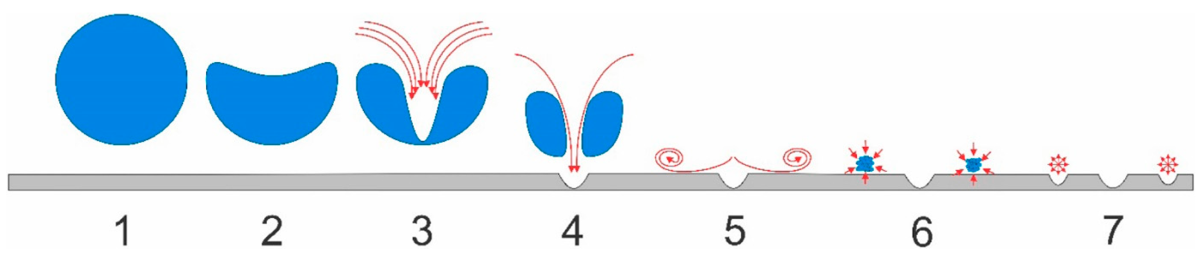
Figure 1. Number of published documents from 2013 to 2022 based on the Scopus database, obtained on 16 November 2022.
Processes 11 00514 g001
Figure 2. Cavitation explained in p-T diagram.
Processes 11 00514 g002
Figure 4. Mechanism of bubble collapse in close proximity to the wall. Reprinted with permission from Ref. [61]. 2023, Elsevier.
Processes 11 00514 g004
Figure 5. Schematic representation of particle breakup in high-speed homogenizer. Adapted with permission from Ref. [70]. 2023, Elsevier.
Processes 11 00514 g005
Figure 6. Rotor–stator type cavitation reactor by Cerecedo and coworkers Reprinted with permission from Ref. [85]. 2023, Elsevier.
Processes 11 00514 g006
Figure 7. (a) Schematic representation of the indentation type RGHC; (b) flow pattern in a single indentation; by Badve and coworkers [80]. Adapted with permission from Ref. [80]. 2023, Elsevier.
Processes 11 00514 g007
Figure 8. Schematic representation of the ARHCR; by Sun and coworkers [114].
Processes 11 00514 g008
Figure 9. Rotating hydrodynamic cavitation device; by Maršálek and coworkers [117]. Reprinted with permission from Ref. [117]. 2023, Elsevier.
Processes 11 00514 g009
Figure 10. SD RGHC; (a) rotor disk; (b) cavitation regions for right-angled rotor design; (c) cavitation regions for 8° design; by Petkovšek and coworkers [108]. Adapted with permission from Ref. [108]. 2023, Elsevier.
Processes 11 00514 g010
Figure 11. SD RGHC, (1) electric motor; (2) rotor disk; (3) front housing; (4) back housing; by Šarc and coworkers [91]. Reprinted with permission from Ref. [91]. 2023, Elsevier.
Processes 11 00514 g011
Figure 12. SD RGHC by Kosel and colleagues [120]. Reprinted with permission from Ref. [120]. 2023, Elsevier.
Processes 11 00514 g012
Figure 13. Schematic representation of the SD RGHC setup by Stepišnik Perdih and coworkers [82].
Processes 11 00514 g013
Figure 14. Axial serrated RGHC; (a) rotor; (b) stator; (c) rotor–stator assembly; by Villaroig and coworkers [41]. Reprinted with permission from Ref. [41]. 2023, John Wiley and Sons.
Processes 11 00514 g014
Figure 15. Axial serrated RGHC; by Fu and coworkers [122]. Reprinted with permission from Ref. [122]. 2023, John Wiley and Sons.
Processes 11 00514 g015
Figure 16. Pinned disk RGHC; initially designed by Gostiša and coworkers [79] Image reused from Ref. [72].
Processes 11 00514 g016
Figure 17. Rotor radial grove RGHC (a) reactor, (b) rotor geometry, and (c) stator geometry; by Song and coworkers [123]. Adapted with permission from Ref. [123]. 2023, Elsevier.
Processes 11 00514 g017
Table 1. Individual stages of bubble collapse in close proximity to the wall. Adapted with permission from Ref. [61]. 2023, Elsevier.
Number on Figure 4Explanation
(1)maximum bubble size is reached
(2)upper boundary collapses faster due to the vicinity of rigid surface
(3)microjet formation and occurrence of water hammer pressure
(4)deformation of the surface
(5)flow moves radially outwards
(6)secondary evaporation/splashing [63]
(7)formation of micro bubbles, spherical collapse, and generation of shockwaves
Table 2. Collected data for WAS treatment studies with RGHCs.
Device TypeSample
Treated
Sample
Parameters
Process
Parameters
Achieved
Effect
Process EfficiencyReference
indentation type RGHCwastewater
from wood
finishing
industry
pH = 6.18
COD0 = 38000 mg/L
V = 4 L
Np = 195
t = 20 min
Q = 39 L/min
T = 20–25 °C
CR = 56% at 2200 RPM4.6 mg COD/kJ *Badve et al. (2013) [80]
CR = 89% at 2200 RPM and 5 g/L of H2O28.4 mg COD/kJ **
SD RGHCWAS from
WWTP
TS > 10 g/L
sCOD0 = 46 mg/L
sKN0 = 6.3 mg/L
(Soluble Kjeldahl Nitrogen)
V = 196 L
Np = 20
t = 55 min
Q = 71 L/min
DD = 57%
12.7% biogas enhancement
sCODcav = 602 mg/L
sKNcav = 71 mg/L
75 kJ/g sCODPetkovšek et al. (2015) [38]
SD RGHCSecondary
Pulp and
Paper Mill
Sludge
V = 500 L
sCOD0 = 509 mg/L
Nt = 8.1 mg/L
Pt = 0.6 mg/L
t = 30 minCR = 46%
sCODcav = 1023 mg/L
Nt;cav = 43 mg/L
Pt;cav = 2.9 mg/L
0.758 kg/€Sežun et al. (2019) [121]
sCODcav = 2895 mg/L
Nt;cav = 128.1 mg/L with NaOH addition (pH 10)
1.835 kg/€
SD RGHCWastewater
influent
sample
pH = 7.8
pH = 7.9
V = 800 L
Np = 30
t = 90 min
Q = 4.4 L
CR = 20% at 2290 RPM
CR = 13% at 2700 RPM
N/AKovačič et al. (2020) [110]
ARHCRSecondary
sewage sludge
pH = 6.5
COD0 = 4480 mg/L
sCOD0 = 34 mg/L
VSS = 2120 mg/L
TS = 3726.5 mg/L
CR = 33% sCODcav = 633 mg/L
VSS = 540 mg/L
92.7% average particle size reduction
SR = 42.3%Kim et al. 2019 [68]
ARHCRsewage sludgeCOD0 = 2350 mg/L sCOD0 = 93 mg/L
particle size 10–1000 μm
pinlet = 0.2 bar
Q = 6.3 L/min
sCODcav = 588 mg/L
94.7% average particle size decrease
Particle size with temperature control in the 10–100 μm range
Particle size without temperature control in the 1–10 μm range
N/AKim et al. (2020) [116]
Multiple SD RGHCWAS or WAS
mixed with
pig slurry
pH = 7.3 ± 0.1
TS = 7200 mg/L
COD0 = 4505 ± 1744 mg/L
sCOD0 = 76 ± 35 mg/L
V = 40 L
5600 RPM
Np = 22
t = 30 min
P = 5730 W
DD = 26%271 kJ/g sCODVilarriogh et al. (2020) [41]
pH = 7.2 ± 0.3
TS = 70,000 mg/L
COD0 = 4505 ± 1744 mg/L
sCOD0 = 6320 ± 1950 mg/L
V = 200 L
t = 240 min
P = 6930 W
DD = 17.4%16 kJ/g sCOD
PD RGHCwastewater
influent
sample
pH = 7.6
COD0 = 1432 mg/L
T0 = 16 °C
V = 200 L
5600 RPM
Np = 15
t = 5.88 min
CR = 28%
COD removal = 813 g COD/h
8.25 kWh/kg COD
3.28 kWh/m3
Gostiša et al. (2021) [79]
pH = 8.1
COD0 = 1432 mg/L
T0 = 16 °C
V = 200 L
t = 6.49 minCR = 31%
COD removal = 815 g COD/h
8.22 kWh/kg COD
3.62 kWh/m3
PD RGHCwastewater
influent
sample
pH = 8.2
COD0 = 648 mg/L
Np = 60
2700 RPM
t = 116 min
P = 5.6 kW
Q = 6.9 L/min
CR = 18%
92.8 g COD reduced; 48 g COD/h
116.7 kWh/kg CODGostiša et al. (2021) [94]
pH = 7.3
COD0 = 635 mg/L
Np = 30
2700 RPM
t = 47 min
P = 6.7 kW
Q = 8.6 L/min
CR = 21%
7.6 g COD reduced; 138.8 g COD/h
48.3 kWh/kg COD
pH = 7.3
COD0 = 635 mg/L
Np = 60
2700 RPM
t = 93 min
P = 6.7 kW
Q = 8.6 L/min
CR = 27%
13.7 g COD reduced; 88.2 g COD/h
76 kWh/kg COD
PD RGHCWASpH = 6.9
EC = 1121 µs/cm
Salinity = 0.36 ppm
DO = 0.39 mg/L
TS = 16.7 ± 0.6 mg/L
VS = 12.4 ± 0.5 mg/L
COD0 = 16.7 ± 0.9 mg/L
sCOD0 = 207 ± 14 mg/L
sTOC0 = 292.5 ± 34.6 mg/L
sTN0 = 146.5 ± 2.1 mg/L
TP0 = 536.5 ± 4.9 mg/L
sTP0 = 65.5 ± 3.5 mg/L
2700 RPM
Δp = 102 kPa
p0 = 22 kPa
Q = 8.0 L/s
P = 6.3 kW
Np = 60
V = 320 L
CR = 5%
DD = 3.3 ± 0.4%
sCODcav = 530 ± 1 mg/L
sTOC = 345 ± 11.3 mg/L
Increase in DOM relevant values
Increase in fluorescence
Decrease of total metal concentration
SE = 1.41·103 ± 0.16·103 kJ/kgTS
SESS = 73 ± 2 kJ/g sCOD
Kolb-Repinc et al. (2022) [72]
3000 RPM
Δp = 99 kPa
p0 = 26 kPa
Q = 8.7 L/s
P = 6.5 kW
Np = 60
V = 320 L
CR = 4%
DD = 6.0 ± 0.6%
sCODcav = 459 ± 57 mg/L
sTOCcav = 331.5 ± 7.8 mg/L
Increase in DOM relevant values
Increase in fluorescence
Decrease of total metal concentration
SE = 1.34·103 ± 0.1·103 kJ/kgTS
SESS = 89 ± 4 kJ/g sCOD
* and ** COD reduction per total energy suplied.
Disclaimer/Publisher’s Note: The statements, opinions and data contained in all publications are solely those of the individual author(s) and contributor(s) and not of MDPI and/or the editor(s). MDPI and/or the editor(s) disclaim responsibility for any injury to people or property resulting from any ideas, methods, instructions or products referred to in the content.

