Abstract
This study provides a basis for designing and optimizing the key components of hanging-cup transplanters. The discrete element method, a high-speed photography test, and indoor soil bin tests were used to explore soil disturbance behavior during the hole drilling process. A comparative analysis of the discrete element method and the high-speed photography test indicated that soil particles are mainly affected by the coupled effects of the shear force and the squeezing force of the planter. The soil disturbance range in the horizontal and longitudinal sections gradually increases with the movement of the planter. The change in the soil particle velocity of the horizontal and longitudinal sections in different zones shows a trend of first increasing, then decreasing, and finally stabilizing. The velocity of soil particles in the longitudinal section varies significantly in the direction of burial. The soil in the horizontal section mainly moves to both sides when the duckbill is opened. The closer the soil particles are to the outer wall of the duckbill, the greater the change in velocity is. The soil bin tests and simulations were carried out under different conditions, but the change trend of the simulation results is consistent with the soil bin test results, proving that the simulation model is reliable. With the forward speed of the transplanter, planting depth, and soil compactness as the test factors, and the hole depth and hole longitudinal length as the response values, an orthogonal test of three factors and three levels was designed. A regression model between each element and response value was established. The optimal parameter combination was obtained when the forward speed was 1.25 km/h, the planting depth was 80 mm, and the soil firmness was 140~150 (N/cm2); these results were experimentally verified.
1. Introduction
Seedling growth and transplanting can contribute to the stress resistance of crops, ensure a stable yield, and promote agricultural income and a safe supply of agricultural products [1,2,3]. When the soil disturbance behavior at the contact interface changes significantly, the hole size changes during the hole drilling operation of a hanging-cup transplanter [4,5]. Part of the soil flows back into the hole, creating an uneven bottom and seriously affecting seedling growth and planting efficiency.
The existing research has mainly focused on the optimal design of planters and hole-size parameters. For example, Seyed et al. [6] designed and created a conical distribution cup to improve planting speed and precision and conducted field tests. Dihingia et al. [7] developed a planting device for a vegetable transplanter driven by a walking tractor and conducted experimental research. Xiang et al. [8] designed and manufactured a rolling hole-shaping transplanting machine based on the functional characteristics of trenching and transplanting and carried out field experiments. Li et al. [9] took the width of the hole opening as the test object and comprehensively considered the positioning of the planting device and the entire machine, the opening and closing times of the duckbill, etc.; they then optimized the design of the bar of a planting mechanism. Li et al. [10] studied the hole size on the membrane from the perspective of structural parameters and characteristic parameters of the motion of a planter and obtained an improved average coefficient of movement. Liu et al. [11] analyzed the formation of a mulching film orifice under the different angular velocities of a planter. When the angular velocity of the planter increased, the longitudinal and horizontal dimensions of the orifice also increased. Soil disturbance behavior is very nonlinear during the hole drilling process, which is difficult to accurately describe using traditional methods. The discrete element method (DEM), which fully considers the influence of soil particles’ physical parameters and their distribution in particle flow, is widely used to simulate the interaction between soil and soil contact components in the field. This method allows the contact and destruction between the particles of the materials and can effectively simulate microdeformation between materials [12,13,14,15,16]. Han et al. [17] used theoretical calculations, the discrete element method, and field tests to optimize the parameters of a hole former. Gao et al. [18] established the discrete element model of a trencher and planting device. The simulation and soil bin test were conducted using the backfill depth and horizontal working resistance as the test indices. Yang et al. [19] studied the operational characteristics of a planter and the interaction with soil using the discrete element method and concluded that the hanging cone cup has superior hole drilling performance. Chen et al. [20] designed a caterpillar rape seedling transplanting and planting mechanism and conducted a discrete element simulation of the cone spike diameter, cone tip chamfer, and depth of soil. The test results showed that the diameter, cone tip chamfer, and penetration depth of the hole-forming component significantly affected the adequate depth and resistance to penetration, and there was substantial interaction among the parameters. Quan et al. [21,22] conducted a discrete element simulation and a soil bin test using the coefficient of soil return in the hole section and soil porosity of the hole wall as the indicators and obtained a relationship between the hole shape and soil disturbance. However, there are few studies on soil disturbance behavior at the contact interface.
Soil disturbance behavior is a complex engineering system that is affected by multiple factors, such as soil spatial distribution and power configuration of transplanters. Therefore, this paper analyzes soil disturbance behavior during the hole drilling process by combining the discrete element method, a high-speed photography test, and indoor soil bin tests. The microscopic movement of soil particles at different positions and sections was systematically analyzed. Soil disturbance behavior was ascertained by comparing and analyzing the high-speed photographic images. Using the hole depth and longitudinal length as the response values, an orthogonal test of three factors and three levels was created using the Design Expert 8.0.6 software(STAT-EASE Inc., Minneapolis, MN, USA); the regression model between each element and response value was established; and the optimal parameter combination was obtained.
2. Materials and Methods
2.1. Hanging-Cup Transplanter Structure and Working Principle
2.1.1. Hanging-Cup Transplanter Structure
As shown in Figure 1, the hanging-cup transplanter is mainly composed of the feeding mechanism, the main beam, the planting mechanism, the earth-covering roller, etc. The planting mechanism primarily consists of a mounting plate, a control plate, and duckbill planters. During the transplanting process, seedlings are placed in the feeding cup. When the duckbill planter rotates to the receiving position, the feeding mechanism throws the seedlings, and the planter receives and carries the seedlings. When the planter turns to a particular position, the roller contacts the cam, and the duckbill begins to drill a hole. At the lowest point, the duckbill planter gradually opens, and the seedlings are planted in the hole under the force of gravity. The mulching ballast wheel completes the operation, and the duckbill closes, ending a transplanting cycle [23,24].
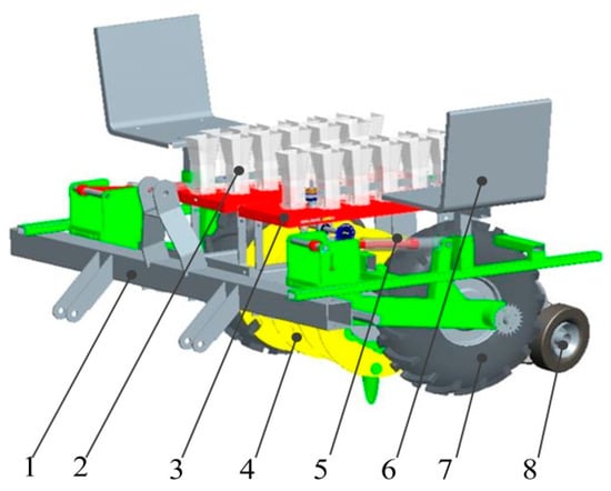
Figure 1.
Three-dimensional model diagram of the transplanter. 1. Main beam; 2. feeding cup; 3. feeding mechanism; 4. planting mechanism; 5. planting depth adjusting for mechanism; 6. seat; 7. ground wheel; and 8. the earth-covering roller.
2.1.2. Analysis of the Movement Process of the Hanging-Cup Transplanter
When the hanging-cup transplanter is used for planting, the planter should rotate at a constant speed with the planting plate and move in a straight line at a constant speed in the horizontal direction [25,26]. As shown in Figure 2, the planter is mainly divided into four stages. In the seedling grafting process (da stage), the planter catches the plug seedling thrown by a manual feeding mechanism. In the seedling loading process (ab stage), the planter carries the plug seedling until the duckbill starts to contact the soil. In the hole drilling and planting process (bc stage), the duckbill changes from closed to open under the cam mechanism during the planter operation, changing from being buried to being unearthed. The duckbill compresses the soil to form a hole. According to the “zero speed seedling” principle, the plug seedling is slipped from the planter into the hole [27]. In the duckbill closing process (cd stage), the duckbill gradually closes, and the earth-covering roller presses the soil in preparation for the following plug seedling. According to the working principle, the hanging-cup transplanter can independently complete various processes, such as seedling grafting, seedling loading, hole drilling, and planting, among which hole drilling is crucial to ensure planting quality. The hole-size parameters are not only related to the structure and movement of the planter but are also closely related to soil disturbance behavior at the contact interface.
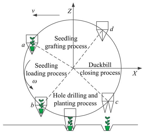
Figure 2.
Motion diagram of the planter.
2.2. Indoor Soil Bin and High-Speed Photography Tests
2.2.1. Test Materials
The high-speed photography test was conducted in the intelligent soil bin laboratory of the School of Mechanical and Electrical Engineering, Inner Mongolia Agricultural University. The test soil was sandy loam, the average soil moisture content was 14.52%, and the soil compactness was 98 N/cm2. A three-point suspension connected the soil tanker and the hanging-cup transplanter. During the test, the frequency of the soil tanker could be adjusted to change the speed of the transplanter, and the feeding mechanism and planting mechanism were driven by a chain drive to complete the delivery of the plug seedlings. The soil was pretreated such that the soil conditions met the requirements of the transplanting operation. First, using a rotary cultivator to repeatedly perform rotary tillage, the soil was sprayed by the system provided by the soil tanker [28,29], and the compaction operation was performed by a compaction roller. Finally, the hole drilling test was performed.
A high-speed photography system was constructed to record the soil disturbance behavior in real time during the test to study the dynamic changes in the soil at the contact interface. As shown in Figure 3, the system is mainly comprised of a high-speed camera, a LED light supplement, a laptop, and a hanging-cup transplanter. During field operation, the duckbill planter creates a particular disturbance to soil particles in the X, Y, and Z directions. This test only photographed and recorded soil disturbance at the Y–Z intersection to facilitate the recording. Without considering the sliding effect of the ground wheel, the soil tanker’s forward speed was set equal to the forward speed of the transplanter. Gypsum powder was used to outline a white marking area set in the forward direction of the transplanter. The high-speed camera was fixed on a tripod with the optical axis perpendicular to the horizontal section of the transplanter. The aperture and the height of the tripod were adjusted to ensure that soil disturbance could be photographed in its entirety. The distance between the lens of the high-speed camera and the plane where the transplanter was located was 1640 mm. The included angle with the horizontal plane was 43°, and the sampling frequency was 450 frames/s (image resolution: 1280 pixels × 1024 pixels).
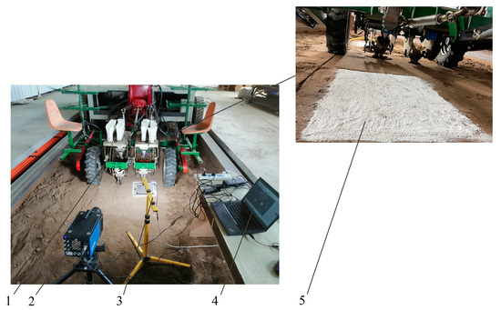
Figure 3.
High-speed photography system construction. 1. Hanging-cup transplanter; 2. high-speed camera; 3. LED fill light; 4. laptop computer; and 5. marker block.
2.2.2. Test Method
The longitudinal length and the depth of the hole were used as the test indices to measure the effect of soil disturbance. The soil bin test was conducted with different working parameters, such as changing the forward speed and the planting depth of the hanging-cup transplanter. After the soil bin test, 30 hole-size samples (hole longitudinal length and hole depth) were randomly estimated. Floating soil was removed from each hole. As shown in Figure 4a, a steel ruler is placed horizontally over the hole. Another is inserted vertically into the bottom of the hole. Thus, the depth of the hole is the reading at the intersection of the two rulers. As shown in Figure 4b, the distance between the two rulers is measured as the hole longitudinal length. As shown in Figure 4c,d, the simulation was completed with the clipping module to profile each hole, and the ruler tool was used to measure the hole longitudinal length and hole depth. Each parameter was repeated several times, and the average value was taken as the final value.
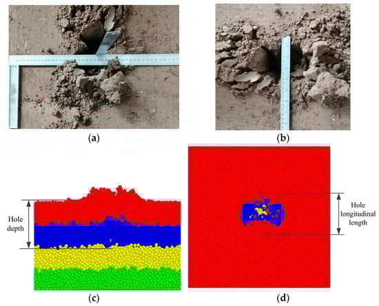
Figure 4.
Hole-size parameters. (a) Test hole depth; (b) test hole longitudinal length; (c) simulated hole depth; and (d) simulated hole longitudinal length.
The soil bin tests and the discrete element simulations were conducted to study the influence of soil disturbance changes on hole size. With the forward speed of the transplanter, planting depth, and soil compactness as the test factors, and the hole depth and hole longitudinal length as the response values, an orthogonal test of three factors and three levels was created using the Design Expert 8.0.6 software(STAT-EASE Inc., Minneapolis, MN, USA). The regression model between each element and the response value was established, and the optimal parameter combination was obtained.
2.3. Establishment of the Planter–Soil Simulation Model
2.3.1. Establishment of the Soil Model
The Hertz–Mindlin bonding model can reflect the cohesion and elasticity between soil particles, and the size of the particle bonding radius can reflect soil moisture content [30,31]. The Hertz–Mindlin bonding model was selected to generate particle groups with specific flexible characteristics. Soil compactness reflects soil porosity and soil particle holding capacity. If soil hardness is high, it will affect the development of the crop’s root system, increase seedling retardation, and reduce crop growth and survival rates. Soil compaction is an essential reference for estimating soil models. Crops, such as tomatoes, peppers, and oil sunflowers, are generally planted at depths of 60–100 mm. The soil compactness was measured and recorded at 60, 80, and 100 mm. The test results are shown in Table 1.

Table 1.
Soil compactness.
To improve the accuracy of the simulation and ensure the efficiency of the calculation, soil particles were set as spherical particles with a filling radius of 3 mm, and the basic parameters were determined according to the literature [32,33]. As shown in Figure 5, a simulation model of the soil and compactness meters is established, and the dropping speed of the compactness meter is set to 50 mm/s. The soil compactness after the simulation was compared to the soil compactness in the soil bin test. The parameters were adjusted several times, and the optimal results are shown in Table 2.
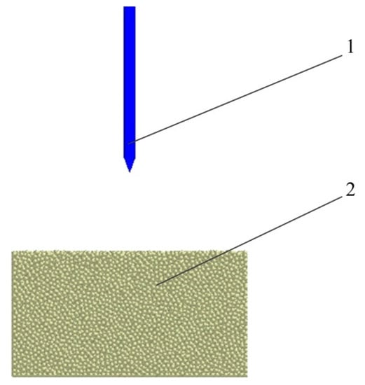
Figure 5.
Simulation model of the soil compactness test. 1. Compactness meter, and 2. soil particles.
Table 2.
HWB model’s calibration values.
As shown in Table 3, the relative error between the actual and simulated soil compactness is less than 20%; therefore, the bonding parameter can be used as the soil simulation parameter to represent natural soil.
Table 3.
Comparison of soil compactness.
2.3.2. Establishment of the Simulation Model
After the overall modeling was completed in Pro/E, the bolts and other fasteners were removed, and other components with consistent movement characteristics were made into a subassembly. Finally, the data were saved in the *.step format and imported into the EDEM 2018 software.
The virtual soil bin size (length × width × height) was 300 mm × 250 mm × 160 mm. A particle factory was built above the virtual soil bin to dynamically generate soil particles, and the soil particles were settled, stacked, and bonded to form a soil model. The simulation model of the planting device–soil is shown in Figure 6. The aim was to visually analyze the effect of soil disturbance at the contact interface on hole morphology. The soil model consists of shallow, middle, deep, and deeper layers with red, blue, yellow, and green soil particles, respectively. The mutual contact model between the planting device and the soil was set as Hertz–Mindlin (no slip). The total movement time was 9 s. The soil particle filling time was 0~4 s, the soil particle bonding time was 5 s, and the planting device simulation time was 5~9 s. At the beginning of the simulation, the planting device was located at one end of the virtual soil bin. The planting device ran in the negative direction of the X axis.
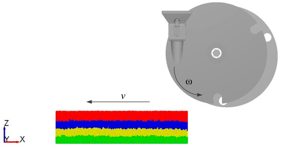
Figure 6.
The planting device–soil simulation model. Notes: The shallow layer is red soil particles. The middle layer is blue soil particles. The deep layer is yellow soil particles. The deeper layer is green soil particles. The X direction is the horizontal movement; the Y direction is the lateral movement; and the Z direction is the vertical movement. v is the forward direction of the transplanter, and ω is the rotation direction of the transplanter.
The simulation model of the planting device–soil was established, and the discrete element simulation was performed under different forward speeds and planting depths. After the simulation, the clipping module was used to cut the hole, and the ruler tool was used to measure the hole depth and hole longitudinal length. Each combination of test parameters involved multiple measurements, and the average value was taken as the final value.
3. Results
3.1. Analysis of Soil Disturbance Behavior at the Contact Interface
3.1.1. High-Speed Photography Analysis of Soil Disturbance Behavior at the Contact Interface
It is difficult to accurately observe the soil disturbance process with the naked eye during the hole drilling process of a hanging-cup transplanter. The analysis of the interaction in the planting device−soil interaction system in an ideal state must be revised to explain the influence of the planter on soil disturbance behavior at the contact interface. Taking the characteristic parameter of motion λ = 1.222, the forward speed of the transplanter v = 1.25 km/h, and the planting depth H = 80 mm as an example, soil disturbance behavior was recorded in real time with a high-speed camera and reproduced with the image postprocessing software TEMA. The surface soil disturbance status was compared and analyzed at different times and locations.
The soil disturbance is shown in Figure 7 (the images are arranged in a chronological order, and the red arrow is the direction of soil movement at the contact interface). In the hole drilling process, soil particles do not come into contact with the planter at the initial stage, so there is no disturbance. As shown in Figure 7a, with the rotation of the planter, the planter reaches the lowest point, and the combined action of the pressure of the planter, the shear force, and the mutual disturbance between soil particles slightly raises the surface soil. When the duckbill gradually opens under the joint action of the cam mechanism and the planter, it shears the soil. When the shear force of a section reaches the soil shear strength limit, cracks form on its surface, shear failure occurs on the soil at the contact interface, and a fan-shaped soil profile is formed on the surface. The contour gradually expands in the opening direction of the duckbill, and the soil structure breaks to create a soil block, as shown in Figure 7b. When the planter leaves the hole, the broken soil continues to be affected by the combined action of the shear force and the squeezing force of the planter. The soil particles further break, and the soil particles flow back into the hole under the action of gravity, as shown in Figure 7c.
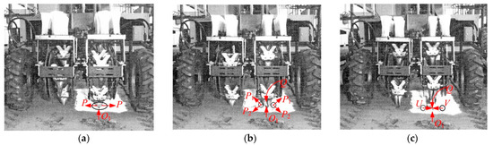
Figure 7.
High-speed photographic image analysis of soil disturbance at the contact interface. (a) The planter reaching the lowest point; (b) the duckbill opening to the maximum; and (c) the planter leaving the soil.
The soil disturbance behavior changed with time and was mainly affected by the combined action of the shear force and the squeezing force of the planter. The soil movement specifically included the squeezing action of the planter on the soil (P), the raising action of the duckbill shearing the soil open to both sides (P1, P2), and the backflow of soil particles into the hole (Q). Some soil moved toward the inside of the hole along the direction of the transplanter (O1). The soil particles inside the hole were further cracked and broken. This not only expanded the contour of soil disturbance but also increased the amount of soil (e.g., U and V) moving in the direction of the planter. Thus, the planting quality of the transplanting operation was affected, and the probability of secondary backflow between soil particles increased.
3.1.2. Comparative Analysis of Soil Disturbance Behavior
The high-speed photographic images and the discrete element simulation of soil disturbance were compared and analyzed at different positions to study the change in soil disturbance behavior under the action of the planter at different positions during the hole drilling process. Using the clipping module of EDEM 2018, the transplanter was profiled in the horizontal and longitudinal directions. In Figure 8, the soil disturbance is shown when the planter is in different situations. During the hole drilling process, the soil disturbance range in the horizontal section and longitudinal section gradually increases with the movement of the planter. The disturbance range of the shallow soil is more extensive, the disturbance range of the middle soil is less extensive, and the disturbance range of the deep soil is the least extensive. As shown in Figure 8(a1,b1,c1), when the planter reaches the lowest point, the soil particles have a small displacement due to the combined action of the shear force and the squeezing force of the planter. As shown in Figure 8(a2,b2,c2), when the duckbill opens to its maximum, the transplanter continues to make a uniform linear motion such that some soil particles move along the front and upper parts of the outer wall of the duckbill. Other soil particles return to the hole, increasing the longitudinal disturbance of the soil. The duckbill cut some soil particles. It moves soil to both sides along the opening direction of the bill, which increases the horizontal disturbance. As shown in Figure 8(a3,b3,c3), when the planter leaves the hole, the broken soil continues to be affected by the combined action of the shear force and the squeezing force of the planter. The soil particles break further, and the soil particles flow back into the hole due to gravity.
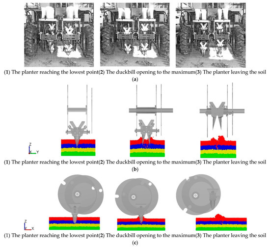
Figure 8.
Analysis of soil disturbance at the contact interface. (a) Horizontal disturbance process of soil under high-speed photography; (b) horizontal disturbance during the simulation process; and (c) longitudinal disturbance during the simulation process.
3.2. Analysis of Soil Disturbance Velocity in Different Sections
3.2.1. Analysis of Soil Disturbance Velocity in the Longitudinal Section
It is necessary to analyze the variation in the velocity of soil particles in the longitudinal section under the action of the duckbill to study the interaction between the planter and the soil during the hole drilling process. Eight rectangular monitoring zones were set in the soil model to monitor the change in soil velocity from the lowest point of the duckbill in the entire disturbed area to the point where it leaves the soil. As shown in Figure 9, the zones are numbered from right to left, and their size (length × width × height) is 22 × 550 × 260 mm.
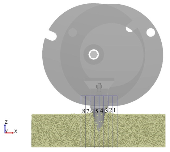
Figure 9.
Diagram of the longitudinal monitoring area layout. Notes: 1–8 are various monitoring zones.
The variation in the soil disturbance velocity for each region of the longitudinal section during the hole drilling process is shown in Figure 10. The test results show that the variation in the soil particle velocity at the longitudinal contact interface first increases, then decreases, and finally stabilizes. As shown in Figure 10b, the variations in the velocities of zones 4 and 5 are much more significant than those of zones 3 and 6, while the velocities of zones 5 and 6 are greater than those of zones 3 and 4. The main reason for these results is that zones 5 and 6 are in the direction of soil penetration, while zones 3 and 4 are in the direction of soil excavation. At this point, the soil disturbance behavior in the direction of soil penetration changes significantly, the soil disturbance is significant, and soil particles flow back into the hole.
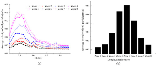
Figure 10.
Variation curves of motion in different regions of the longitudinal section. (a) Particle motion curve in the longitudinal section; and (b) velocity variation in different zones.
3.2.2. Analysis of Soil Disturbance Velocity in the Horizontal Section
It is necessary to analyze the variation in the velocity of soil particles in the horizontal section under the action of the duckbill to study the interaction between the planter and the soil during the hole drilling process. Eight rectangular monitoring zones were set to monitor the change in soil velocity from the lowest point of the duckbill in the entire disturbed area to the point where it leaves the soil. As shown in Figure 11, the zones are numbered from right to left, and their size (length × width × height) is 22 × 550 × 260 mm.
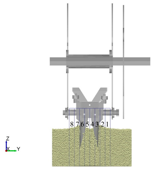
Figure 11.
Diagram of the horizontal monitoring area layout. Notes: 1–8 are various monitoring zones.
The variation in the soil disturbance velocity in each area of the horizontal section is shown in Figure 12. The test results show that the variation in the soil particle velocity at the longitudinal contact interface first increases, then decreases, and finally stabilizes. In addition, the velocities of zone 4 and zone 5 are relatively low. As shown in Figure 12b, the change in the velocities of zones 3 and 6 is much more significant than that of zones 4 and 5. The main reason for this result is that the duckbill moves to both sides during the hole drilling process. The closer the soil particles are to the outer wall of the duckbill, the greater the soil disturbance is and the more significant the change in soil particle velocity is.
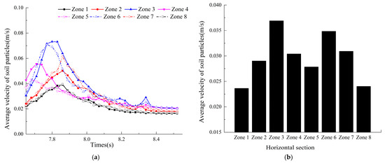
Figure 12.
Variation curves of motion in different regions of the horizontal section. (a) Particle motion curve in the horizontal section; and (b) velocity variation in different zones.
3.3. Effect of Soil Disturbance Behavior on the Hole-Size Parameters
3.3.1. Effect of Planting Depth on Soil Disturbance
To analyze the influence of soil disturbance behavior on the hole longitudinal length and hole depth at different planting depths during the hole drilling process, soil bin tests and simulations were performed at various planting depths (H = 60, 80, and 100 mm) with a forward speed of v = 1.25 km/h. The test results are shown in Figure 13. When the forward speed of the transplanter is constant, the hole longitudinal length and hole depth increase gradually with the increasing planting depth. The main reason for this result is that the soil particle velocity of the horizontal and longitudinal sections increases gradually, while the soil disturbance changes considerably, ultimately affecting the hole-size parameters.
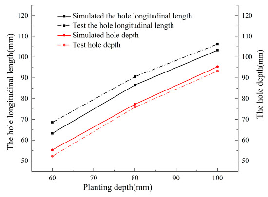
Figure 13.
Variation curve of hole parameters at different planting depths.
3.3.2. Effect of Forward Speed on Soil Disturbance
To analyze the influence of soil disturbance behavior on the hole longitudinal length and hole depth under different forward speeds during the hole drilling process, soil bin tests and simulations were conducted at varying forward speeds (v = 1, 1.25, 1.5, 1.75, and 2.0 km/h) at a planting depth of H = 80 mm. The test results are shown in Figure 14. The results of the simulations are consistent with those of the soil bin test results: when the planting depth is constant, the hole longitudinal length gradually becomes more significant, while the hole depth decreases as the forward speed increases. The main reason for this result is that the soil particle velocity of the horizontal and longitudinal sections increases gradually. The soil particles flow back into the hole, causing the hole bottom to be uneven, and ultimately affecting the hole-size parameters.
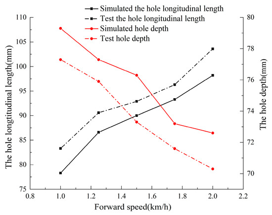
Figure 14.
Variation curve of hole parameters at different forward speeds.
3.4. Parameter Optimization of Hole Drilling Test
3.4.1. Box–Behnken Test Design
This study used the forward speed of the transplanter, planting depth, and soil compactness as the test factors and the hole depth and hole longitudinal length as the response values. An orthogonal test of three factors and three levels was designed using the Design Expert 8.0.6 software(STAT-EASE Inc., Minneapolis, USA). A total of 17 test combinations were conducted, and each combination was repeated several times. The average value was selected as the final value. The test factors and levels are shown in Table 4. Based on the test design, the hole drilling test was conducted in the soil bin, the response values were calculated for each test combination, and the test results are shown in Table 5.
Table 4.
Factors and levels.
Table 5.
Test design and results.
3.4.2. Establishment and Significance Analysis of Regression Model
The Design Expert software was used to conduct the multiple regression fitting and variance analysis on the data from the hole drilling test, and the results are shown in Table 5. The regression models of the forward speed (X1), the planting depth (X2), the soil compactness (X3), the hole longitudinal length (L), and the hole depth (h) were established using Formulas (1) and (2).
where are the hole longitudinal length and hole depth, in mm, and are the forward speed (km/h), the planting depth (mm), and the soil compactness (N/cm2).
As shown in Table 6, a P < 0.05 (PL = 0.002; Ph < 0.0001) for the model of the hole longitudinal length (L) and hole depth (h) indicates that the established regression model is significant. For the hole longitudinal length, it can be seen that the primary variables X1, X2, and X3 are highly effective. It can be seen from the F value that the factors affecting the hole longitudinal length are ranked as X2 > X1 > X3, i.e., planting depth > forward speed > soil compactness. For the hole depth, the primary items X2 and X3 are highly significant, and X1 has a considerable impact. It can be seen from the F value that the factors affecting the hole depth are ranked as X2 > X3 > X1, i.e., planting depth > soil compactness > forward speed. The determination coefficients (R2) of the regression equations are 0.9695 and 0.9958, with both being close to 1, showing that the parameters of this model account for more than 90% of the variation in the hole parameters. These parameters can be used for further optimization analysis.
Table 6.
Variance analysis of the regression model.
3.4.3. Parameter Optimization
The optimization module in the Design Expert 8.0.6 software was used to determine the best parameter combination of the hole drilling test. The optimal parameter combination was a forward speed of 1.25 km/h, a planting depth of 80 mm, and a soil compactness of 140~150 (N/cm2); for these values, the hole longitudinal length was 69.9 mm, and the hole depth was 77.1 mm. Multiple sets of repeated tests were conducted to verify the reliability of the optimal parameters. The relative error was within a reasonable range. The best combination of the process parameters is consistent with actual agronomic requirements.
4. Discussion
This study used soil compaction as a variable and studied it in an indoor soil bin. However, certain variables, such as soil compaction, transplanter vibration, and ground wheel slip, cannot be accurately controlled in an actual field. To better adapt the transplanting machine to the soil compaction of actual terrain, many transplant experiments concerning different factors are being planned for the future, so the prediction model can be established through in-depth learning. A multi-objective optimization is also being planned for the future.
5. Conclusions
In this study, soil disturbance behavior during a hole drilling process was studied by combining the discrete element method, a high-speed photography test, and indoor soil bin tests.
The comparative analysis using the discrete element method and high-speed photography showed that soil particles were mainly affected by the coupled effects of the shear force and the squeezing force of the planter. The soil disturbance range in the horizontal and longitudinal sections gradually increased with the movement of the planter. The change in soil particle velocity in the horizontal and longitudinal sections of the different zones showed a trend of first increasing, then decreasing, and finally stabilizing. The velocity of soil particles in the longitudinal section varied significantly in the direction of burial. The soil in the horizontal section mainly moved to both sides when the duckbill was opened. The closer the soil particles were to the outer wall of the duckbill, the greater the change in velocity was.
The soil bin tests and simulations were carried out under different conditions, and the trend of the simulation results was consistent with that of the soil bin test results, proving that the simulation model was reliable. With the forward speed of the transplanter, planting depth, and soil compactness as the test factors, and the hole depth and hole longitudinal length as the response values, an orthogonal test of three factors and three levels was designed. The regression model of each factor and response value was established. The optimal combination of parameters was obtained when the forward speed was 1.25 km/h, the planting depth was 80 mm, and the soil firmness was 140~150 (N/cm2); this combination was verified experimentally.
Author Contributions
Conceptualization, X.L. (Xuying Li); methodology, F.Z. and H.B.; software, F.Z. and J.C.; data curation, Y.Z. and X.L. (Xuening Liu); formal analysis, writing—original draft preparation, and writing—review and editing, F.Z. All authors have read and agreed to the published version of the manuscript.
Funding
This project was funded by the National Natural Science Foundation of China (NSFC) (32160423) and the Natural Science Foundation of the Inner Mongolia Autonomous Region of China (2020MS05055).
Institutional Review Board Statement
Not applicable.
Informed Consent Statement
Not applicable.
Data Availability Statement
The data presented in this study are available from the first author (F.Z.) upon request at zfd19508@hotmail.com.
Acknowledgments
The authors gratefully acknowledge the financial support provided by the National Natural Science Foundation of China (NSFC) (32160423) and the Natural Science Foundation of the Inner Mongolia Autonomous Region of China (2020MS05055). We also appreciate the work of the editors and the reviewers of the paper.
Conflicts of Interest
The authors declare no conflict of interest.
References
- Jin, X.; Yuan, Y.W.; Ji, J.T.; Zhao, K.X.; Li, M.Y.; Chen, K.K. Design and implementation of anti-leakage planting system for transplanting machine based on fuzzy information. Comput. Electron. Agric. 2020, 169, 105–204. [Google Scholar] [CrossRef]
- Sharma, A.; Khar, S. Current developments in vegetable transplanters in developing countries: A comprehensive review. Int. J. Veg. Sci. 2022, 28, 417–440. [Google Scholar] [CrossRef]
- Wen, Y.S.; Zhang, L.A.; Huang, X.M.; Yuan, T.; Zhang, J.; Tan, Y.; Feng, Z. Design of and experiment with seedling selection system for automatic transplanter for vegetable plug seedlings. Agronomy 2021, 11, 2031. [Google Scholar] [CrossRef]
- Jin, X.; Pang, J.; Ji, J.T.; He, Z.T.; Wang, S.G. Experiment and simulation analysis on high-speed up-film transplanting mechanism. Int. Agric. Eng. J. 2017, 26, 95–102. [Google Scholar]
- Tong, J.H.; Wu, C.Y.; Jiang, H.Y.; Yu, Y.X.; Rao, X.Q. Optimizing the path of seedling low-density transplanting by using greedy genetic algorithm. Comput. Electron. Agric. 2017, 142, 356–368. [Google Scholar] [CrossRef]
- Javidan, S.M.; Mohammadzamani, D. Design, construction and evaluation of semi-automatic vegetable transplanter with conical distributor cup. SN Appl. Sci. 2019, 1, 1–8. [Google Scholar] [CrossRef]
- Dihingia, P.C.; Prasanna Kumar, G.V.; Sarma, P.K. Development of a hopper-type planting device for a walk-behind hand-tractor-powered vegetable transplanter. J. Biosyst. Eng. 2016, 41, 21–33. [Google Scholar] [CrossRef]
- Xiang, W.; Wu, M.L.; Guan, C.Y.; He, Y.M.; Luo, H.F.; Yan, B. Design and test of transplanting hole-forming machine for rapeseed potted seedlings. Trans. Chin. Soc. Agric. Mach. 2017, 48, 40–48+58. [Google Scholar]
- Li, P.B.; Yan, H.; Wang, P.L.; Li, N.; Wu, H.H.; Han, L.H. Optimization and test of small pant spacing planting mechanism rod for transplanter. Trans. Chin. Soc. Agric. Mach. 2020, 51, 72–78. [Google Scholar]
- Li, X.Y.; Wang, Y.W.; Lu, G.C.; Zhang, B.; Zhang, H.J. Optimization design and test of Dibble-type transplanting device. Trans. Chin. Soc. Agric. Eng. 2015, 31, 58–64. [Google Scholar]
- Liu, Y.; Wang, S.G.; Mao, H.P.; Li, B.; Wang, T.; Li, Y.X.; Han, L.H. Trajectory optimization and test of basket-type planting devices. Agric. Res. Arid Areas 2019, 37, 291–298. [Google Scholar]
- Hang, C.G.; Yao, Y.X.; Huang, Y.X.; Li, W.; Zhu, R.X. High-speed photographic analysis of the soil disturbance affected by subsoiler rake angle. Agric. Eng. Int. CIGR J. 2017, 19, 42–50. [Google Scholar]
- Qiu, Y.Q.; Guo, Z.J.; Jin, X.; Zhang, P.G.; Si, S.J.; Guo, F.G. Calibration and Verification Test of Cinnamon Soil Simulation Parameters Based on Discrete Element Method. Agriculture 2022, 12, 1082. [Google Scholar] [CrossRef]
- Tian, Z.W.; Ma, W.; Yang, Q.C.; Yao, S.; Guo, X.Y.; Duan, F.M. Design and experiment of gripper for greenhouse plug seedling transplanting based on EDM. Agronomy 2022, 12, 1487. [Google Scholar] [CrossRef]
- Wang, J.W.; Xu, C.S.; Xu, W.L.; Fu, Z.D.; Wang, Q.; Tang, H. Discrete element method simulation of rice grain motion during discharge with an auger operated at various inclinations. Biosyst. Eng. 2022, 223, 97–115. [Google Scholar] [CrossRef]
- Yan, D.X.; Yu, J.Q.; Wang, Y.; Zhou, L.; Tian, Y.; Zhang, N. Soil Particle Modeling and Parameter Calibration Based on Discrete Element Method. Agriculture 2022, 12, 1421. [Google Scholar] [CrossRef]
- Han, C.J.; Xu, Y.; You, J.; Zhang, J.; Yuan, P.P. Parameter optimization of opener of semi-automatic transplanter for watermelon seedlings raised on compression substrate. Trans. Chin. Soc. Agric. Eng. 2019, 35, 48–56. [Google Scholar]
- Gao, F. Design and Experimental Study on Key Components of Sugarcane Seedling Transplanter. Master’s Thesis, JiangSu University, Zhenjiang, China, 2020. [Google Scholar]
- Yang, Q.Z.; Zhang, R.Y.; Jia, C.P.; Li, Z.Y.; Zhu, M.L.; Addy, M. Study of dynamic hole-forming performance of a cup-hanging planter on a high-speed seedling transplanter. Front. Mech. Eng. 2022, 8, 896881. [Google Scholar] [CrossRef]
- Chen, C.P.; Quan, W.; Wu, M.L.; Zhang, W.T. Parameter optimization of vertical soil-filling hole-forming parts for rapeseed transplantation based on discrete element method. J. Hunan Agric. Univ. (Nat. Sci.) 2019, 45, 433–439. [Google Scholar] [CrossRef]
- Quan, W.; Wu, M.L.; Dai, Z.W.; Luo, H.F.; Shi, F.G. Design and testing of reverse-rotating soil-taking-type hole-forming device of pot seedling transplanting machine for rapeseed. Agriculture 2022, 12, 319. [Google Scholar] [CrossRef]
- Quan, W.; Wu, M.L.; Luo, H.F.; Chen, C.P.; Xie, W. Soil hole opening methods and parameters optimization of pot seedling transplanting machine for rapeseed. Trans. Chin. Soc. Agric. Eng. 2020, 36, 13–21+327. [Google Scholar]
- Zhang, X.Z. Design Analysis and Experimental Research on Transplanting Device of Dibble-Type Transplanter. Master’s Thesis, Inner Mongolia Agricultural University, Hohhot, China, 2014. [Google Scholar]
- Zhao, Z.W. Design and Research of the Planting Depth Control System of the Hanging-Cup Transplanter. Master’s Thesis, Inner Mongolia Agricultural University, Hohhot, China, 2021. [Google Scholar]
- Du, S.; Wang, W.B. Kinematic analysis of the planting part under the soil contact condition. Mach. Des. Manuf. 2016, 299, 246–249. [Google Scholar] [CrossRef]
- Pei, X.K. Optimal Design and Experiment of Transplanting Mechanism for Apple Seedlings. Master’s Thesis, Heibei Agricultural Univeraity, Baoding, China, 2021. [Google Scholar]
- Feng, J.; Qin, G.; Song, W.T.; Liu, Y.J. The Kinematic Analysis and Design Criteriaof the Dibble-type Transplanters. Trans. Chin. Soc. Agric. Mach. 2002, 33, 48–50. [Google Scholar]
- Hang, C.G.; Zhang, P.P.; Li, W.; Huang, Y.X.; Zhu, R.X. Experiment research on influence of rake angle on soil hardness variation under sub-soiling. J. Chin. Agric. Mech. 2016, 37, 36–40. [Google Scholar] [CrossRef]
- Huang, Y.X.; Hang, C.G.; Yuan, M.C.; Tao, W.B.; Zhu, R.X. Discrete element simulation and experiment on disturbance behavior of subsoiling. Trans. Chin. Soc. Agric. Mach. 2016, 47, 80–88. [Google Scholar]
- Zeng, Z.W.; Ma, X.; Cao, X.L.; Li, Z.H.; Wang, X.C. Critical review of applications of discrete element method in agricultural engineering. Trans. Chin. Soc. Agric. Eng. 2021, 52, 1–20. [Google Scholar]
- Zhao, S.H.; Gao, L.L.; Yuan, Y.W.; Hou, L.T.; Zhang, X.; Yang, Y.Q. Maize straw motion law in subsoiling operation using discrete element method. Trans. Chin. Soc. Agric. Eng. 2021, 37, 53–62. [Google Scholar]
- Hang, C.G.; Gao, X.J.; Yuan, M.C.; Huang, Y.X.; Zhu, R.X. Discrete element simulations and experiments of soil disturbance as affected by the tine spacing of subsoiler. Biosyst. Eng. 2018, 168, 73–82. [Google Scholar] [CrossRef]
- Zeng, F.D.; Li, X.Y.; Zhang, Y.Z.; Zhao, Z.W.; Cheng, C. Using the discrete element method to analyze and calibrate a model for the interaction between a planting device and soil particles. INMATEH-Agric. Eng. 2021, 63, 413–424. [Google Scholar] [CrossRef]


Disclaimer/Publisher’s Note: The statements, opinions and data contained in all publications are solely those of the individual author(s) and contributor(s) and not of MDPI and/or the editor(s). MDPI and/or the editor(s) disclaim responsibility for any injury to people or property resulting from any ideas, methods, instructions or products referred to in the content. |
© 2023 by the authors. Licensee MDPI, Basel, Switzerland. This article is an open access article distributed under the terms and conditions of the Creative Commons Attribution (CC BY) license (https://creativecommons.org/licenses/by/4.0/).