1. Introduction
Climate change is a large problem humanity faces due to the carbon dioxide (CO
2) emissions into the atmosphere. Most emissions are due to the consumption of fossil fuels. According to the International Energy Agency (IEA), in 2019, 33 Gt of CO
2 was released into the atmosphere [
1]. On the other hand, according to the “Waste Heat Recovery: Technology and Opportunities in U. S. Industry” report [
2], just in the United States, the amount of unrecovered waste heat at temperatures lower than 150 °C was 75 × 10
9 kW per year. According to the Oak Ridge Laboratory, most industries’ waste heat sources are exhaust gases produced by burners, furnaces, dryers, heaters, and heat exchangers using liquids at high temperatures [
3]. To reduce the consumption of fossil fuels, and diminish CO
2 emissions, many studies have been carried out on the study and development of organic Rankine cycles (ORC). These cycles are similar to Rankine cycles, but they utilize an organic fluid instead of steam, and their capacities are considerably lower than the former, typically varying from 20 kW to 200 kW, although some organic cycles can even produce only a few watts. Currently, some microturbines can be found in the market from a few kW up to 1000 kW [
4]. Moreover, the temperatures to drive these cycles are lower than those required for the steam Rankine cycle; hence, these cycles are typically used to recover industrial waste heat or with renewable energies such as geothermal or solar.
Due to the relevance that ORCs have taken mainly in the last two decades, a considerable number of papers have been published about these systems. Just in the last few years, five bibliographic reviews have been published regarding different aspects of ORCs [
5,
6,
7,
8,
9]. One more was published on the optimization of organic Rankine, Kalina, and Goswami cycles and modifications of them driven with low heat sources such as solar, geothermal, and industrial waste heat in which the authors identified the best cycles for different specific operating conditions [
10].
Regarding the use of different working fluids to be used in ORCs, some studies mainly focused on finding the best working fluids. In this regard, Herath et al. [
11] modeled a geothermal ORC plant using R134a, R245fa, benzene, methanol, ethanol, acetone, and propane as working fluids. The results showed that the ORC was more efficient using benzene and methanol. The highest efficiency was 18.5% at 194 ºC using benzene. Zhang et al. [
12] analyzed more than fifty fluids. The analysis considered the saturated–vapor curves, which were divided into wet, dry, and isentropic depending on the slope of the saturated–vapor curve. According to the authors, the triangle formed by the critical point and the liquid and vapor points in saturated conditions at the turning point significantly impact the system performance. The highest efficiencies were obtained using working fluids with turning points higher than 200 °C and triangle areas lower than 6 kJ/kg. From the analysis, it was found that the best working fluids were toluene and benzene, achieving efficiencies of 29% and 28.5%, respectively. Dai et al. [
13] carried out an energy and exergy study of a basic ORC using twelve hydrocarbon working fluids operating with four different heat sources. From the analysis, it was found that cyclohexane achieved the highest energy efficiencies reaching a value of 21.43%. Pezzuolo et al. [
14] developed a tool for fluid selection of a basic and a recuperative ORC. More than eighty fluids were analyzed in the systems. At a heat source temperature of around 170 °C, the highest efficiencies were obtained in the basic ORC using ethanol, benzene, and toluene with values of 24.2%, 23.2%, and 22.9%, respectively. For the case of the recuperative ORC, the maximum efficiencies were obtained with benzene, toluene, and cyclohexane, with energy efficiencies of around 25.6%. Braimakis and Karellas [
15] performed the exergy optimization of a two-stage ORC integrated by two-single ORCs using diverse fluids. The proposed system could achieve exergy efficiencies up to 25% higher than basic ORCs. The highest exergy efficiencies were around 50% using cyclopentane, cyclohexane, and toluene.
Different kinds of hybrid cycles integrating an ORC and diverse technologies or heat sources have been proposed in the last years for producing two or even three different outputs, including power production. Some of these studies have proposed the simultaneous production of power and heating [
16,
17], power and desalination [
18], power and hydrogen [
19,
20,
21,
22,
23], and also power and cooling. Regarding these systems, Voeltzel et al. [
24] reported the study and optimization of a cogeneration system for the simultaneous production of power and cooling using the ammonia–water mixture driven with low-grade heat. Two different configurations varying the rectifier position were analyzed in which the absorption cooling cycle was in parallel with the ORC. The authors found that the most efficient configuration is in which the rectifier is effective for both cooling and power production. Wang et al. [
25] proposed an ORC integrating ejector-compression cooling system (ECS). This system has the advantage of using an ejector to circulate and increase the refrigerant pressure in a similar way to a conventional compression cooling system, but without consuming electricity to run the compressor, since the ejector operates thermally. The highest energy and exergy efficiencies were 18.16% and 59.16%, respectively, at a geothermal brine temperature of 190 °C. Lizarte et al. [
26] analyzed the performance of an ORC and a cascade compressor cooling system (CCS) since, in a cascade cooling system, the pressure and temperature differences are considerably higher compared to single compression cooling systems. The proposed cycle can achieve temperatures as low as −55 °C. The power produced by the ORC was used as the input power of the cooling cycle. The highest COP and exergy efficiencies were 0.79 and 31.6%, respectively. Javanshir et al. [
27] proposed a similar system integrated by an ORC and a CCS. The system was analyzed using R134a, R22, and R142a. The highest energy and exergy efficiencies were obtained using R143a, reaching 27.2% and 57.9%, respectively. The electricity production cost was 60.7 USD/GJ. Sun et al. [
28] modeled a two-stage G-ORC recovering the residual heat of an absorption cooling system (ACS) using H
2O/LiBr to produce power and cooling simultaneously; since the use of a second stage in the ORC, the system was able to increase the net power output by 10%. Ehyaei et al. [
29] proposed a similar system but using R134a. The use of ACS increased energy efficiency from 9.3% to 47.3%. The system’s minimum electricity cost was 3.3 USD/MWh. Leveni and Cozzolino [
30] conducted an energy and exergy analysis of the same system producing a net power of 5 kW and obtaining an exergy efficiency of 40.98%. Other studies were performed proposing a third or even a fourth output; Li et al. [
31] presented a geothermal ORC for cooling, heating, and power using twenty zeotropic mixtures. In addition to the conventional components of an ORC, the system was integrated with two heat pumps. One of them was used to produce heat, and the other for cooling. The heat input to the evaporator of the heat pumps was supplied by the expander exhaust gases. Due to the integration of the heat pumps, the system was able to produce power, heating, and cooling. At a heat source temperature of 90 °C, the highest net power output, cooling capacity, and exergy efficiency were 92 kW, 2450 kW, and 0.62%, respectively, for R141b/R134a. Pashapour et al. [
32] proposed a system integrated by a Brayton cycle, an ORC, and an ACS using H
2O/LiBr to produce power, heating, and cooling simultaneously, driven with geothermal energy. In the proposed system, the gas leaving the Brayton turbine is first used by a regenerator and then by the ORC to generate hot water and power, respectively. At the same time, geothermal is employed to reheat the ORC and to drive the absorption cooling system. Because of the good integration between the three cycles, the system achieved high energy and exergy efficiencies. The highest exergy efficiency was 50.65%, while the maximum COP was 0.5. Although this system achieved high exergy efficiency, it requires many components and very high operating temperatures close to 1250 °C, and Sharifishourabi and Chadegani [
33] proposed a system for simultaneous cooling production, hot water, heating, hydrogen, and power. The system was integrated by an ORC, a triple-effect ACS using H
2O/LiBr, a dehumidification system (DS), and an electrolyzer, all driven by solar energy. In the system, the heat produced by the CPC was used to drive the ORC to produce the power. The gas leaving the turbine was used as heat input for the cooling system, while the power produced by the turbine was used in the electrolyzer to produce H
2. The system achieved an energy utilization factor of 0.39, a COP of 1.34, an energy efficiency of 14.4%, and an exergy efficiency of 26%. Although this system is not as efficient as that reported by Pashapour et al. [
32], it has the advantage of being driven with solar energy and operating at lower temperatures.
As can be concluded from the literature review, although there are some studies related to the simultaneous production of power and cooling, none of them consist of the integration of an ORC and a double-effect absorption system. As was stated, the organic Rankine cycles are suitable for producing power with heat sources at significantly lower temperatures than typical Rankine cycles. Therefore, although quantitatively, the power production obtained by organic cycles is less attractive, they offer an efficient way to take advantage of heat sources at intermediate temperatures.
On the other hand, the main advantage of the double-effect absorption cooling system over the single-effect is a more significant refrigerant production, which results in a better coefficient of performance. Moreover, regarding the working mixtures used for absorption cooling systems, currently, the most used pairs have been the LiBr-H2O and the NH3-H2O; however, both pairs had some relevant drawbacks. Since in the LiBr-H2O mixture, the water is the refrigerant, the cooling systems operating with this mixture cannot operate at temperatures under 0 °C, thus limiting its application to air-conditioning systems. On the other hand, the NH3-H2O has the inconvenience of requiring a rectification process, and since the proposed system is a double-effect system, two rectifiers would be needed to operate it, increasing not only the cost but also decreasing its efficiency. The NH3-LiNO3 mixture has been proposed as an alternative mixture that does not require rectification processes and can operate at temperatures below 0 °C.
In conclusion, the present study proposes the production of cooling and power mainly by exploiting heat sources at intermediate temperatures (160–220 °C), which include renewable sources, such as geothermal or solar energy, but also industrial waste heat or exhaust gases of combustion processes. Moreover, the proposed working fluid in the absorption subsystem is a relatively new mixture with some interesting advantages regarding the H
2O/LiBr working pair. In some aspects, the proposed working pair also has presented better results than the ammonia/water mixture [
34,
35,
36,
37]. Concerning the organic fluid, the ORC modeling was carried out using four different fluids: benzene, cyclohexane, methanol, and toluene. These fluids were chosen based on the presented bibliographic review since several authors [
11,
12,
13,
14,
15] found these fluids were among the most efficient or promising at intermediate temperatures. For the criterion of wet/dry/isentropic fluid, Toluene, Benzene, and Cyclohexane are classified as “dry fluids”, while methanol is a wet fluid; such selection seeks to explore the relative operational advantages of dry fluids over wet fluids. Furthermore, a remarkable subject about the working fluids in both subsystems is that they present either zero or low global warming potential. Thus, this study proposes the present system as an attractive and sustainable solution to generate clean cooling and power from several possible sources with better efficiency than that corresponding to the separated cycles.
2. System Description
A basic ORC is analogous to the steam Rankine cycle. It consists of four main components, an evaporator, a turbine, a condenser, and a pump. The main difference between these two cycles is that ORCs use organic fluids instead of water, as in the Rankine cycle. Another difference is that while the Rankine cycle is normally used to produce a significant amount of power, the ORCs are generally used for small and medium capacities varying, in general, between 20 kW and 200 kW, although 500 kW microturbines can now be found in the market. Because of the low capacity production, ORCs normally use renewable energies such as solar, geothermal, or industrial waste heat.
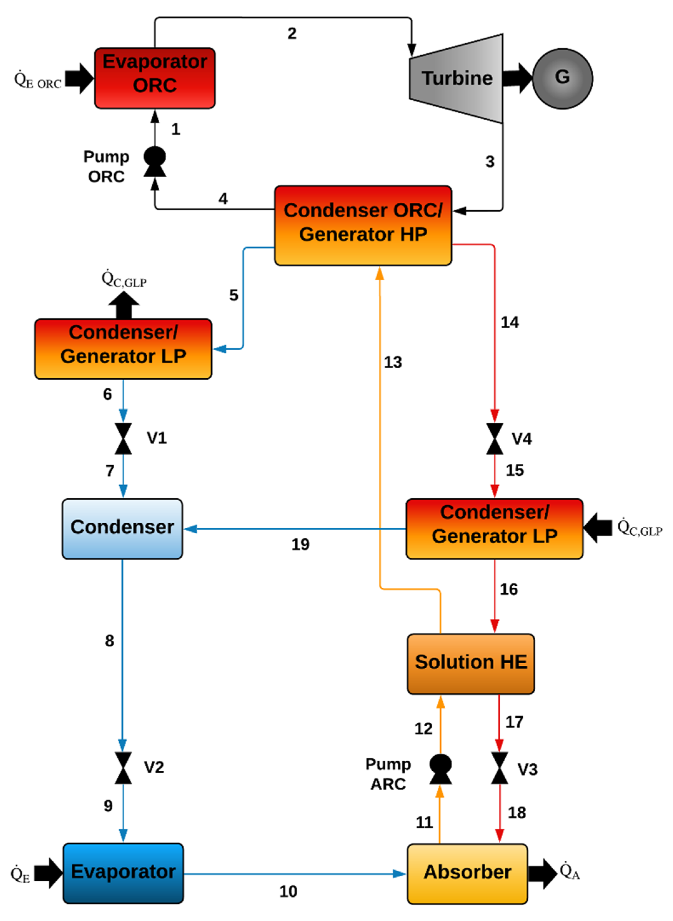
Figure 1 shows a basic ORC coupled with a double-effect ACS. As can be seen, the liquid leaving the pump (1) enters the evaporator, where it is evaporated by supplying thermal energy. Then, the working fluid leaving the evaporator (2) enters the expander, reducing its pressure and temperature, (3) producing mechanical work and electricity by using an electrical generator. The organic fluid leaving the turbine passes through a condenser ORC/generator HP, where it is condensed, leaving the component as a saturated liquid (4). The heat delivered from the condensation process is used to desorb the refrigerant of the double-effect ACS.
The ammonia as a superheated vapor leaving the condenser ORC/generator HP passes to the condenser/generator LP, where it is condensed, leaving this component as a saturated liquid (6). Then, the ammonia passes through valve V1 (7), leaving it as a vapor-liquid mixture due to the partial evaporation caused by the expansion process. At these conditions, the vapor–liquid mixture mixes inside the condenser with the vapor coming from the condenser/generator LP (19), leaving the condenser as a saturated liquid to flow through the expansion valve V2. Under these conditions, the ammonia refrigerant enters the evaporator producing the cooling effect. Next, the ammonia in a vapor phase leaving the evaporator (10) enters the absorber, where it is absorbed by the low-refrigerant solution coming from the condenser/generator LP. The refrigerant-concentrated solution at the exit of the absorber (11) is then pumped (12) and heated up as it passes through the solution heat exchanger and the condenser ORC/generator HP (13). Once the solution with a high refrigerant concentration is heated in the generator HP by the heat delivered from the condenser of the ORC [
3,
4], the refrigerant in a vapor phase is produced (5), and a solution with a low amount of refrigerant leaves the component (14). The solution leaving this component (14) passes through valve V4 (15) and then the condenser/generator LP, where it is heated up by the heat delivered by the condensation processes carried out on the other side of the heat exchanger. This way, the second stream of refrigerant is produced (19). The solution leaving the component with the lowest ammonia concentration passes through the solution heat exchanger (17) and then through valve V3 (18), completing the cycle. Because the ACS produces two streams of refrigerant, this cycle is known as a double effect.
5. Results and Discussion
In this section, the most relevant results for the theoretical evaluation of the proposed cycle are presented. Among the performance indicators considered are the cooling load () produced by the evaporator of the DEACS, the power produced by the turbine () of the ORC, the energy utilization factor (EUF), and the exergy efficiency of the system ().
For complex systems, such as the one proposed in the present study, the change in a parameter usually affects more than one operating variable, so it is not convenient to analyze the isolated effect that a variable has on the system performance; instead, it is better to analyze the effect that a set of variables has on each of the main indicators for a given system. Below are the theoretical results of the operation of the proposed system when the DEACS uses the ammonia–lithium nitrate mixture (NH3-LiNO3), and the ORC uses benzene (C6H6), toluene (C7H8), methanol (CH3OH) and cyclohexane (C6H12).
5.1. System Operation with Ammonia–Lithium Nitrate and Benzene
For the operating condition corresponding to benzene (see
Table 9),
Figure 3 presents the effects of the heat source temperature (
), turbine inlet pressure (
), and cooling temperature (
) on the cooling load, which, for the described operating conditions, is between 56.7 kW and 73.8 kW.
Previously, it was described that a heat supply to the ORC (
) at higher temperatures allows the cycle operation at higher pressures so that both parameters are closely linked. From
Figure 3, it is evident that the cooling capacity decreases as the heat supply temperature and the higher system pressure (
) increase. This decrease is because the temperature of the working fluid in the turbine discharge lowers as
increases, although the pressure at the turbine discharge is constant. This effect happened because of the consideration of an isentropic process of expansion in the turbine. This means a reduction in the thermal load supplied to the DEACS (
), resulting in a detriment of the cooling load produced by the system.
From
Figure 3, it is also possible to note that the evaporation temperature of the absorption system (
) significantly affects its cooling capacity. That is, under any operating condition, the proposed system presents a higher cooling capacity as the cooling temperature is increased.
Regarding the turbine power, it is evident from
Figure 4 that it mainly depends on the difference in pressures before and after the turbine, which is limited by the heat source temperature (
). Therefore, the higher heat source temperatures allow a greater range of operating conditions and a higher pressure at the turbine inlet; this is the reason why at a pressure of 1900 kPa, it is possible to obtain the highest power production (12.82 kW) for the selected operating condition.
From the analysis of
Figure 4, it is observed that, at the constant inlet and outlet turbine pressures, an increase in
generates a slight drop in power production, which seems to be opposed to the operating principles of the Rankine cycle. This effect happens since if
is increased, the enthalpy of the fluid at the turbine inlet and outlet also increases; however, the enthalpy increase at the discharge is slightly more significant, causing a power decrease. In
Figure 4, the aforementioned effect seems to be related to the change in the cooling temperature; however, when analyzing the data obtained, it was corroborated that the slight decrease in power production in the turbine of the ORC has no relationship with the cooling temperature of the DEACS. If the temperature and pressure were kept at the turbine outlet, the increase in the temperature for the supplied heat would produce an increment in turbine power.
To date, it has been shown that increasing
and
reduces the cooling capacity but enhances the turbine power. Since the proposed system combines the production of power and cooling, it is convenient to present the results based on a dimensionless parameter representing the system performance. The energy utilization factor (EUF), from the perspective of the first law of thermodynamics, objectively describes the performance of a system producing different useful effects.
Figure 5 presents the influence of the heat source temperature (
), the maximum pressure of the system (
), and the cooling temperature (
) on the EUF.
From
Figure 5, it is evident that increasing the pressure at the inlet of the turbine benefits the system operation since higher values of the EUF are obtained. However, the EUF increase depends on factors such as the
value, the pressure increment, and the temperature of the working fluid. On the other hand, it is also observed that, for a given pressure, increasing the temperature results in the detriment of the system performance due to the considerations of isentropic expansion and constant discharge pressure at the turbine. This modification slightly affects the cooling load and the turbine power, whose effects result in the trends shown in
Figure 5.
Since the cooling temperature have no effect on the turbine power, and the EUF accounts for the turbine and cooling loads,
Figure 5 shows that the effect of cooling temperature on the EUF is equivalent to the effect of the cooling temperature on the cooling load. That is, the system offers better performance when the required cooling temperature is higher. The range of values for the EUF at three different cooling temperatures is shown in
Table 10, where it is possible to observe that, at the reported conditions, the effect of reducing the cooling temperature by 4 °C will lead to a reduction of close to 5% of the energy utilization factor.
As the EUF, exergy efficiency is a performance parameter that objectively describes any system operation based on the second law of thermodynamics.
Figure 6 shows the combined effect of the higher pressure and temperature of the ORC on the exergy efficiency for two cooling temperatures corresponding to −4 °C and 4 °C.
Figure 6 shows that, with a low performance, the proposed system can operate from 400 kPa and 160 °C up to 1900 kPa when the heat supplied to the ORC is at least 220 °C. In such conditions, the system reaches an exergy efficiency equal to 0.37 with a cooling temperature of −4 °C.
As in the case of the EUF, increasing the heat supply temperature makes it possible to improve the system performance from the point of view of exergy efficiency. The values for this parameter, for a cooling temperature of −4 °C, went from 0.13 (at 180 °C and 400 kPa) to 0.37 (at 220 °C and 1900 kPa).
Regarding the effect of cooling temperature on exergy efficiency, it is observed that better efficiency corresponds to a lower temperature. This makes sense because, from the second-law point of view, the exergy of a system is proportional to the temperature difference between the system and the reference state. In this study, a standard reference state of 25 °C and 1 atm was considered. Thus, the cooling process occurring at the lowest temperatures (in this case, −4 °C) corresponds to a greater temperature difference concerning that of the reference state or, equivalently, greater exergy efficiency of the system carrying out such a process.
5.2. System Operation with Ammonia–Lithium Nitrate and Cyclohexane
The saturation pressures of cyclohexane for the heat supply temperatures considered () are similar to the saturation pressures of benzene previously presented. For this reason, the operating conditions at which the system performance was analyzed are very similar for both working fluid combinations. Below are the main observations of the performance of the proposed system when the ORC operates with cyclohexane.
Figure 7 shows the cooling capacity at different heat sources and cooling temperatures. The maximum cooling load obtained with cyclohexane was 83.5 kW at 4 °C and a turbine inlet pressure of 600 kPa. The minimum cooling load was 50.85 kW at −4 °C and was obtained at a pressure of 1700 kPa.
By comparing
Figure 3 and
Figure 7, it can be verified that both the cooling load trends and values are very similar to those obtained with benzene, except that the system with cyclohexane achieves the same performance at slightly lower heat source temperatures. For example, at a pressure of 1100 kPa at the turbine intake, the system using cyclohexane can produce 59.02 kW of cold at −4 °C, with heat supplied at 190 °C. Regarding benzene, it reaches a cooling load of 58.76 kW at the same cooling temperature but requires heat supplied at 200 °C, which, in this application, is an interesting advantage of cyclohexane over benzene. On the other hand, a disadvantage of cyclohexane compared to benzene is that, in general, for a given source temperature, the pressure range at which it is possible to operate the system is more restricted than that of benzene.
Figure 8 shows the produced power by the proposed system at different operating conditions. It is observed that when the pressures in the intake and discharge of the turbine remain constant, the turbine power tends to decrease slightly by increasing the heat source temperature. In the case of cyclohexane, the maximum turbine power (11.3 kW) is reached at the maximum turbine inlet pressure (1700 kPa). On the other hand, when
adopts the lowest value, the turbine power is minimal, and the cooling load is maximum. At this condition, the turbine power barely reaches 2.2 kW for heat supplied at 160 °C.
An evident behavior from
Figure 8 is that the power gain in the turbine, due to the
increase, is not linear, but it is a function of the pressure level from which it starts. Therefore, for example, at a heat source temperature of 180 °C, increasing the pressure from 500 to 600 kPa produces an increase of 34.5% in the turbine power, while an increase from 600 to 700 kPa, causes an increment of only 21.2%. This fact highlights the convenience of determining an adequate pressure level to achieve the objectives sought; for this objective, the EUF analysis can be very useful. The behavior of EUF as a function of
,
, and
is presented in
Figure 9. It is shown that, as shown for benzene, increasing
up to a certain level allows it to reach higher EUF values.
To date, it has been shown that regardless of the working fluid utilized, the turbine power and cooling load depend mainly on the and values. Likewise, it has been shown that the operating condition that favors the maximum turbine power negatively impacts the cooling load, so an intermediate level for this parameter could be the most suitable to balance both products.
Figure 9 shows that the maximum value of the cyclohexane EUF was 0.762, obtained at a pressure of 1100 kPa and a temperature of 190 °C, although for pressures of 900 kPa and 1300 kPa, for temperatures of 180 °C and 200 °C, respectively, the EUF is very similar. This fact offers the possibility of operating in a wide range of conditions without significantly affecting the system performance from the perspective of the first law of thermodynamics. Therefore, the choice of the operating condition in such a range depends on the effect to improve, either cooling or power.
Figure 10 shows the system performance from a second-law point of view. In this case, the influence of the main operating parameters on the exergy efficiency is shown. For example, in
Figure 10, it can be observed that, as in the case of the EUF, for a given temperature, increasing the pressure at the turbine intake increases the exergy efficiency; however, unlike the EUF, which does not necessarily benefit from an increase in pressure and temperature, the best exergy efficiency values are obtained at the highest heat source temperature and pressure.
Figure 10 shows that exergy efficiency reached a maximum of 0.35 when the heat was supplied to the system at 220 °C,
equals 1800 kPa, and the cooling load was provided at −4 °C; on the other hand, the lowest exergy efficiency (in the range of conditions presented) was obtained when the heat was supplied at 170 °C,
was kept at 400 KPa, and the cooling load was provided at 4 °C.
5.3. System Operation with Ammonia–Lithium Nitrate and Methanol
In the case of methanol, the saturation pressures corresponding to the heat source temperatures are different from those for benzene and cyclohexane. Due to this difference, the operating conditions for the system utilizing methanol are limited. This is the reason why the results presented below consider an operating condition slightly different from that selected for the previously analyzed fluids, particularly for the pressures in the ORC. The system behavior results operating with methanol in the ORC are presented below.
Figure 11 presents the cooling load achieved by the system when it operates with methanol in the ORC. It can be observed that the effects of pressure and temperature on the cooling load are similar to those described above.
From a quantitative point of view, for the cooling temperatures analyzed, there is a slight increase in the cooling load achieved by the operation with methanol. This increase could be attributed to the fact that this power corresponds to a lower expansion pressure (). However, it was found that, under the same operating conditions, for the system operating with methanol, the cooling load was slightly higher (74.5 kW) than that achieved with benzene (74.08 kW) and cyclohexane (73.9 kW).
Regarding the turbine power,
Figure 12 shows that with methanol, the observed trends are contrary to those observed before. For constant pressures in the ORC, it is noticed that the turbine power is slightly increased as the heat source temperature augments. This behavior is different from the corresponding to the previously discussed fluids. This happened for the same reasons explained in
Figure 4. However, in the case of methanol, the enthalpy increase is more significant in the inlet than in the outlet, causing a slight increase in the turbine power as the heat source temperature is augmented.
Figure 12 also shows that the turbine power achieved (7.9 kW) when the system operates with methanol is lower than that achieved when using benzene (11.4 kW) or cyclohexane (9.43 kW) at the same ORC pressure condition. However, with benzene and cyclohexane, the turbine power achieved is higher than with methanol, even at lower heat source temperatures. For example, for the system operating with methanol, at a pressure of 1100 kPa, the minimum heat source temperature required to produce cooling at 4 °C is 215 °C. In the case of the system operating with benzene or cyclohexane, even greater turbine power is produced with heat supplied at 190 °C.
As for the energy utilization factor, it is found between 0.62 and 0.76, which are lower values than those obtained by the system with benzene and cyclohexane.
Figure 13 shows that the highest EUF value is obtained when the system operates at the highest possible pressure. This behavior differs from the case of cyclohexane, whose highest EUF was attained at an intermediate pressure.
From
Figure 13 also can be noticed that, like the behavior observed with benzene, when
is kept constant, the highest EUF is achieved for an intermediate heat source temperature. Thus, for any pressure, augmenting the heat source temperature from that point would result in a decrease in the EUF due to the reasons discussed for the previously analyzed fluids. Such a trend, observed for benzene and methanol, contrasts with the corresponding cyclohexane, whose behavior shows that an increase in the heat source temperature from any point generally results in a lower EUF.
Regarding the exergy efficiency,
Figure 14 shows its highest value is approximately 0.26. It is significantly lower than the value corresponding to benzene and cyclohexane. As in the previous cases, from the second-law point of view, the best system performance is obtained when the ORC operates at the highest pressure and temperature and when the DEACS supplies a cooling load at the lowest temperature (in this case, −4 °C).
5.4. System Operation with Ammonia–Lithium Nitrate and Toluene
Compared to the organic fluids previously analyzed, for the considered heat source temperatures range, the saturation pressures of toluene are the lowest. This fact limits the use of toluene as the working fluid of the ORC, which means that the operation of the proposed system is possible exclusively at temperatures above 180 °C. In addition, it was found that when the system operates with toluene, a condensation temperature of 30 °C considerably limits the conditions at which the system can operate. For that reason, in the case of toluene, a condensation temperature of 24 °C was considered.
It also was found that the operating parameters corresponding to toluene have the most linear response to changes in the operating variables.
Figure 15 shows that the highest cooling load was 82.07 kW, achieved at the lowest pressure (
) and the lowest heat source temperature (180 °C). For these conditions, the cooling load with benzene and cyclohexane reached 80.3 kW and 80.1 kW, respectively, while 80.4 kW of cooling at 4 °C was obtained utilizing methanol.
The lowest cooling load achieved with toluene was 69.8 kW, obtained with heat supplied at 220 °C, a cooling temperature of −4 °C, and a turbine inlet pressure of 1000 kPa. For the same condition, the system achieved cooling loads of 70.09 kW, 69.4 kW, and 72.9 kW with benzene, cyclohexane, and methanol, respectively, demonstrating that the fluid used in the ORC does not have a significant influence on the cooling load.
Figure 16 shows the turbine power as a function of the main parameters. In the case of the operation with toluene, the system can reach a maximum power of 6.9 kW when the heat is supplied at 220 °C and the turbine inlet pressure is 1000 kPa. Under these same conditions, with benzene, cyclohexane, and methanol, the turbine power was: 7.02 kW, 6.57 kW, and 6.71 kW, respectively. It is worth mentioning that, in the condition described, the system can produce cooling from −4 °C; however, the minimum required temperature (at the specified conditions) is 220 °C. For this reason, only one point for such a condition appears in
Figure 16.
On the other hand, when the system operated with toluene, the minimum turbine power was 1.81 kW, with a minimum pressure of 500 kPa, at 205 °C. Under the same conditions, for the other fluids analyzed, the system obtained turbine powers of: 1.80 kW, 1.70 kW, and 1.71 kW for benzene, cyclohexane, and methanol, respectively.
Regarding the EUF,
Figure 17 shows that when the system operates with toluene, its performance is different compared to that of the other analyzed fluids. It was found that, from the first-law point of view, the best operating condition reached a EUF of 0.82, achieved for the lowest temperature and the lowest pressure of the system (
). The same performance was obtained at the same condition for benzene and cyclohexane, while for methanol, this parameter reached 0.83.
Figure 17 also shows that, for the system operating with toluene, the worst energy performance corresponded to a EUF equal to 0.72, obtained when heat is supplied at 205 °C and 500 kPa. For benzene, cyclohexane, and methanol, this parameter corresponds to 0.73, 0.72, and 0.74, respectively.
Finally,
Figure 18 shows the system performance from a second-law perspective. The exergy efficiency for the system operating with toluene coincides with that of the other fluids analyzed since the maximum exergy efficiency corresponds to the maximum heat source temperature and the maximum operating pressure in the ORC.
The maximum exergy efficiency was obtained for heat supplied at 220 °C and 1000 kPa, and cooling produced at −4 °C. Such value, corresponding to 0.26, was also reached at the same conditions by the system operating with benzene and methanol, while when the fluid was cyclohexane, the exergy efficiency was 0.25.
5.5. Performance Comparison for the ORC Working Fluids
Table 11 presents a comparison of the main performance parameters for the four organic fluids utilized in the present study. The comparison is carried out at one selected operating condition corresponding to the maximum heat supply temperature (220 °C), a pressure difference of 500 kPa in the ORC (1000–500 KPa), a condenser-generator temperature of 120 °C, and a condensation temperature of 30 °C, for cooling being produced at −4 °C.
From the comparison of the organic fluids, due to the similar values achieved for the different performance parameters, it could be thought that the selection of the organic fluid does not significantly affect the performance parameters in
Table 11; however, it is important to mention that the working fluid is a key parameter on the determination of the operating conditions at which the integrated system can work. In other words, although the system performance with the different organic fluids is similar, some fluids have operational advantages over others, such as higher operating pressure ranges or lower activation temperatures with similar performance for a given operating condition. For example, for the described operating condition, benzene and cyclohexane can offer a similar behavior if heat is supplied from 200 °C and 195 °C, respectively, while methanol and toluene necessary require a minimum activation temperature of 220 °C.
Regarding the system’s cooling and power capacities, these are directly dependent on the thermal load supplied to the system in the ORC evaporator. As we previously described, for the results presented in this section, a constant amount (100 kW
th) of heat supplied to the ORC’s evaporator was considered. Based on this parameter, the mass flow rate in the organic cycle and the rest of the components of the absorption cycle were determined in such a way that, if this parameter is changed, the corresponding cooling load and turbine power will change proportionally. For a heat supply at 180 °C, constant pressures on the ORC, a condensing temperature of 24 °C, a condenser/generator temperature of 100 °C, and the minimum evaporation temperature (−4 °C),
Table 12 presents the influence of the change on the amount of heat supplied to the ORC, on the turbine power (
), the cooling load (
), energy utilization factor (
), and exergy efficiency (
).
From
Table 12, it can be proved that changing the amount of heat supplied to the ORC’s evaporator affects the turbine power and the cooling load linearly, as it was expected. Hence, a key step in the prospective design of a system such as the one proposed in this work should consider, as a first step, the available heat that could potentially be supplied to the ORC to accordingly size the main components.
Another important fact, evident from
Table 12, is that the amount of heat supplied affects only quantitatively the system performance since the energy utilization factor and the exergy efficiency remain undisturbed as the heat supply is changed. The reason for that is that these parameters are mainly affected by the operative conditions, as it is shown in
Table 12.
6. Conclusions
The present study presented and discussed the theoretical performance of a new system for simultaneous power and cooling. The proposed system is based on integrating a power cycle and a cooling cycle. The power cycle was an organic Rankine cycle (ORC), and the cooling cycle was a double-effect absorption cooling system (DEACS). For the ORC operation, the use of four organic fluids was considered. These fluids are benzene, cyclohexane, methanol, and toluene. For the DEACS, the ammonia–lithium nitrate mixture was used. The results discussion was based on the evaluation of the main operating parameters’ effect on the most significant performance parameters, such as the cooling load, the turbine power, the energy utilization factor, and the exergy efficiency.
It was found that the heat source temperature () and the higher pressure of the ORC () have a great influence on the system performance since the ORC operating conditions determine the thermal load supplied to the DEACS.
As for the main parameters of the DEACS, it was found that, in addition to the cooling temperature, the condenser-generator temperature () is also an important parameter since it limits the system’s operating range. However, it was found that the variation in this temperature keeping the rest constant does not significantly affect the system performance from the quantitative point of view.
From the information presented, it was observed that the conditions that favor the cooling load (lower pressure in the intake of the turbine) result in the detriment of the turbine power and vice versa. Regarding the cooling load, it was proved that, for any operating condition, the cooling load was higher than the turbine power since the minimum cooling produced by the system with any combination of working fluids is above 50 kW, while the maximum turbine power is less than 12.8 kW.
On the other hand, from the comparison of the different combinations, it is possible to conclude that, under the considerations to which the present analysis was carried out, the fluid used in the ORC has a significant impact neither on the turbine power nor on the cooling produced; however, it influences how the changes in operating parameters affect the system performance. Therefore, it is also concluded that the ORC working fluid selection is closely related to the operating conditions in which the system can work.
The analysis of the system results with benzene and cyclohexane showed that the performance of both substances is very similar in the qualitative and quantitative aspects. Nevertheless, for some conditions, it was found that although the system operating with benzene offers a wider range of operating conditions, which represents an advantage in terms of its operability, the system with cyclohexane achieves the same performance at slightly lower heat source temperatures. On the other hand, for some operative conditions, the system utilizing methanol obtained cooling loads slightly higher than those obtained with the other fluids analyzed. However, the maximum pressure for the ORC at which the system can operate with methanol is limited in comparison to that of the other fluids. This fact could be an advantage when considering that, with a lower operating pressure, similar or even better performance than the obtained with the other organic fluids is achieved with methanol. On the other hand, it is known that benzene and cyclohexane freeze at temperatures around 6 °C; however, it is important to mention that there is no risk of solidification for using them in the proposed system since they are only present in the organic cycle, which in general, operates at temperatures above 100 °C.
From the comparison between the different working fluids, it was found that the main operating parameters did not vary considerably for the different used working fluids, but the highest energy utilization factor and efficiencies of 0.76 and 0.27, respectively, were obtained with methanol.
Regarding the performance of the system operating with toluene, it was found that, although it is possible to operate in a relatively wide range of temperatures for each pressure, the minimum heat source temperatures that make possible the system operation are higher than those corresponding to the other fluids analyzed. For this reason, it is considered that toluene does not represent any advantage when used as the working fluid of the proposed system concerning the other organic fluids analyzed in this study.


