
Waste Heat Recovery from Converter Gas by a Filled Bulb Regenerator: Heat Transfer Characteristics


Abstract
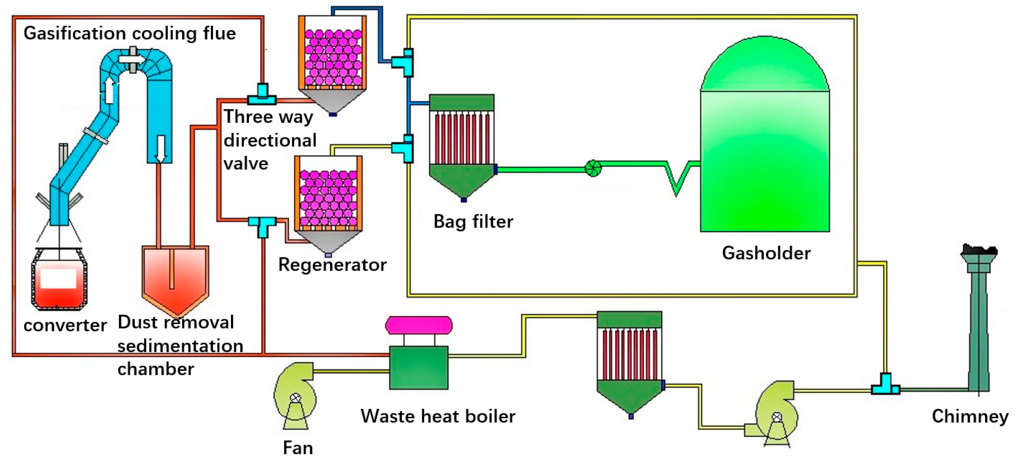
:1. Introduction
- (1)
- Preliminary dedusting of a dedusting sedimentation chamber
- (2)
- Heat exchange and coarse dust removal of the regenerator
- (3)
- Reversing of gas and inert gas in the regenerator
- (4)
- Gas purification and recovery: Inert flue gas purification and waste heat recovery
2. Mathematical Model of Heat Transfer and Flow Process
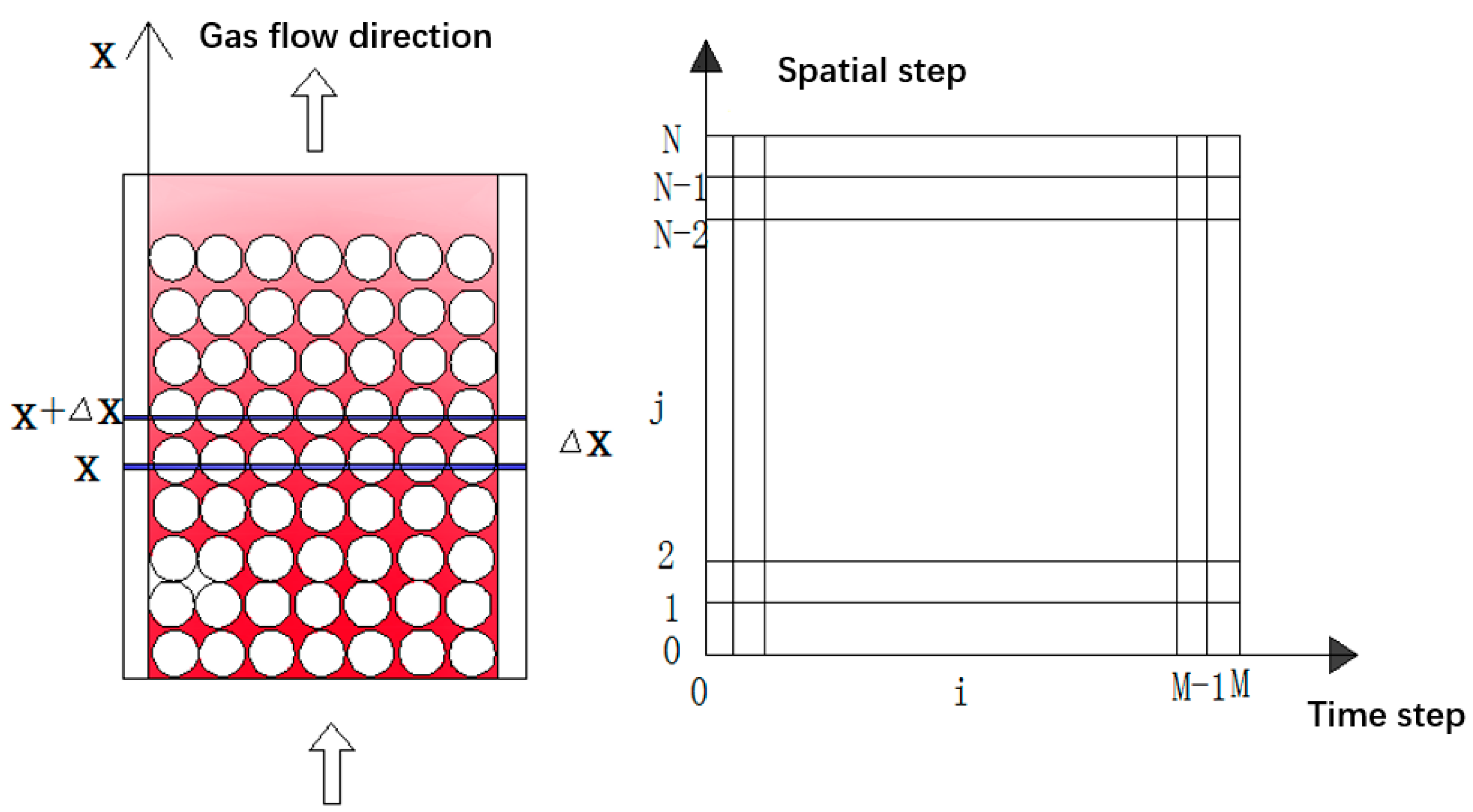
2.1. Mathematical Model of Heat Transfer Process in Regenerator
- (1)
- Flue gas heat absorption or heat release process;
- (2)
- Smoke retention heat release or blowing heat absorption;
- (3)
- Convective heat transfer process between gas and regenerator surface;
- (4)
- Radiation heat transfer process between gas and regenerator surface;
- (5)
- Unsteady heat conduction, heat storage, and heat release process in the regenerator.
- (1)
- There is no heat conduction between the filled balls (compared with the convective heat transfer coefficient, the thermal conductivity between spheres is very small).
- (2)
- The porosity of the regenerator is equal everywhere, and the gas velocity distribution is uniform on any cross-section of the regenerator.
- (3)
- The gas composition and flow rate do not change with time.
- (4)
- Ignore the impact of commutation (mixing of hot and cold fluids, retention in regenerator during commutation).
- (5)
- The heat loss between the regenerator and the environment is ignored.
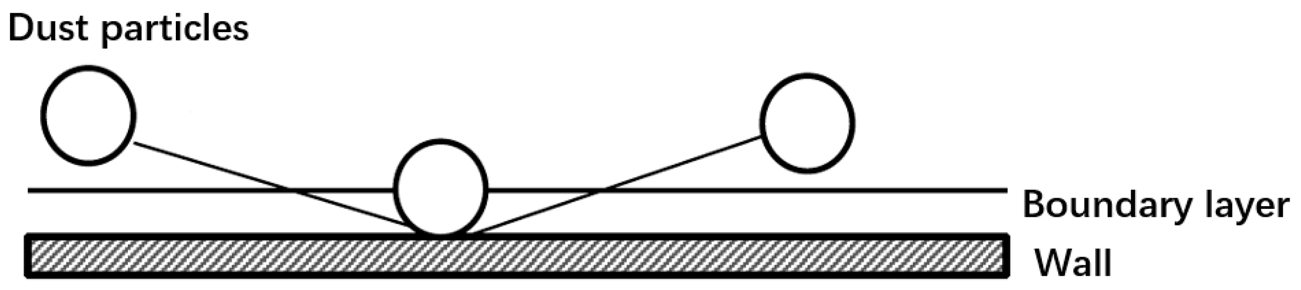
2.2. Treatment of Soot Filtration Process in the Model
2.3. Effect of Dust Particles in Gas on Convective Heat Transfer
2.4. Radiation Heat Transfer in Gas
2.5. Flow Resistance Loss of Gas in Regenerator
2.6. Solve Steps of Equations
- (1)
- Parameter input and initialization;
- (2)
- Mesh division and step calculation;
- (3)
- From the beginning of the heating period, according to the initial temperature of the regenerator and the flue gas, the temperature and pressure of the regenerator in the heating period are calculated in turn with the time step method;
- (4)
- According to the commutation conditions, the initial conditions of the temperature field in the cooling period are determined from the temperature field in the heating period, and the temperature and pressure in the cooling period regenerator are calculated in turn with the time step method;
- (5)
- After the end of the heating period and the cooling period, judge whether the result reaches the iteration calculation number. If it meets the number, enter (6); otherwise, use the temperature field at the end of the cooling period as the initial temperature field of the heating period, enter (3);
- (6)
- Calculate the average gas outlet temperature, temperature efficiency, and thermal efficiency of the regenerator.
3. Results and Discussion
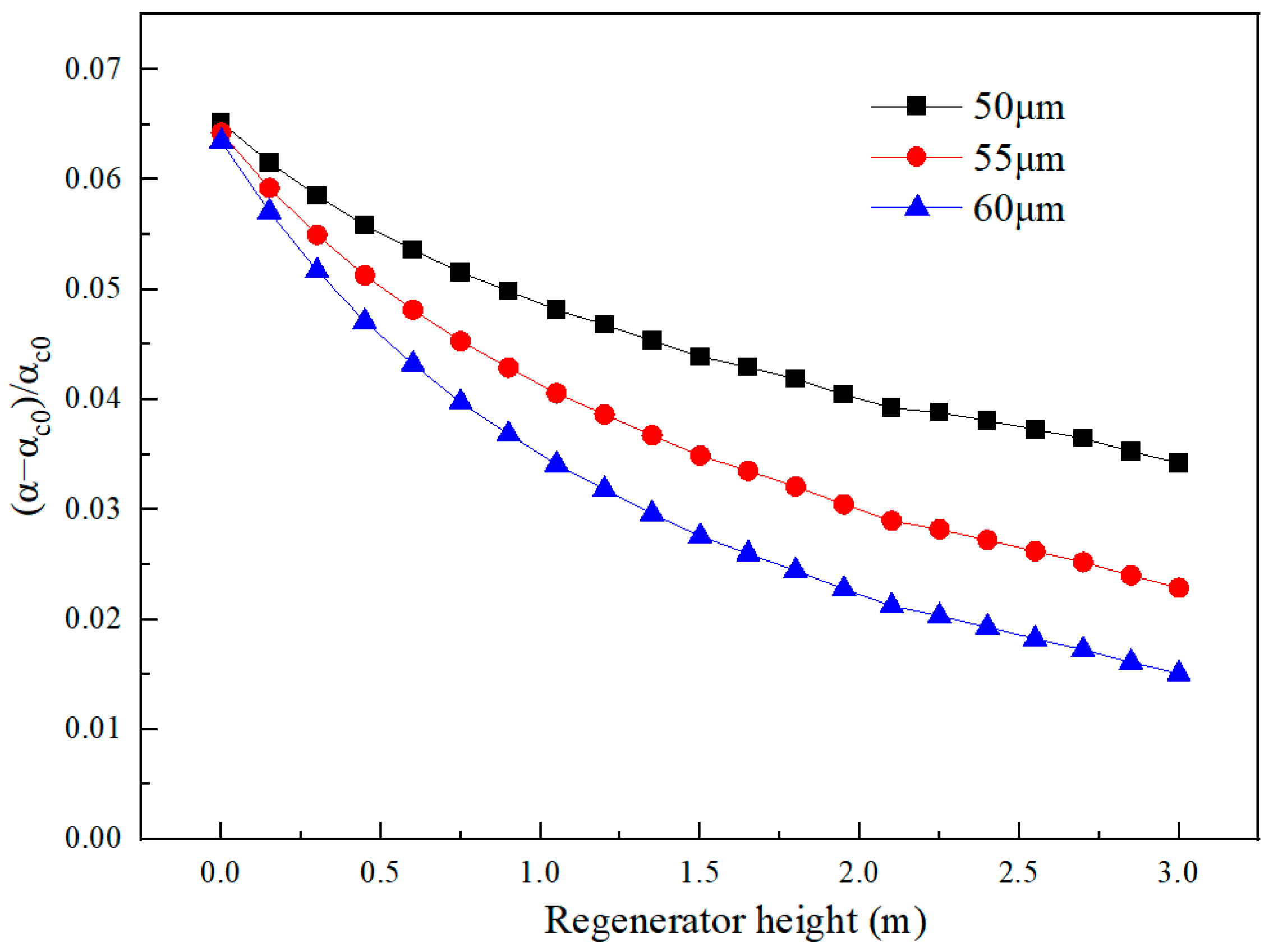
3.1. Effects of Soot Particle Size on Gas Phase Heat Transfer and Dust Removal Efficiency
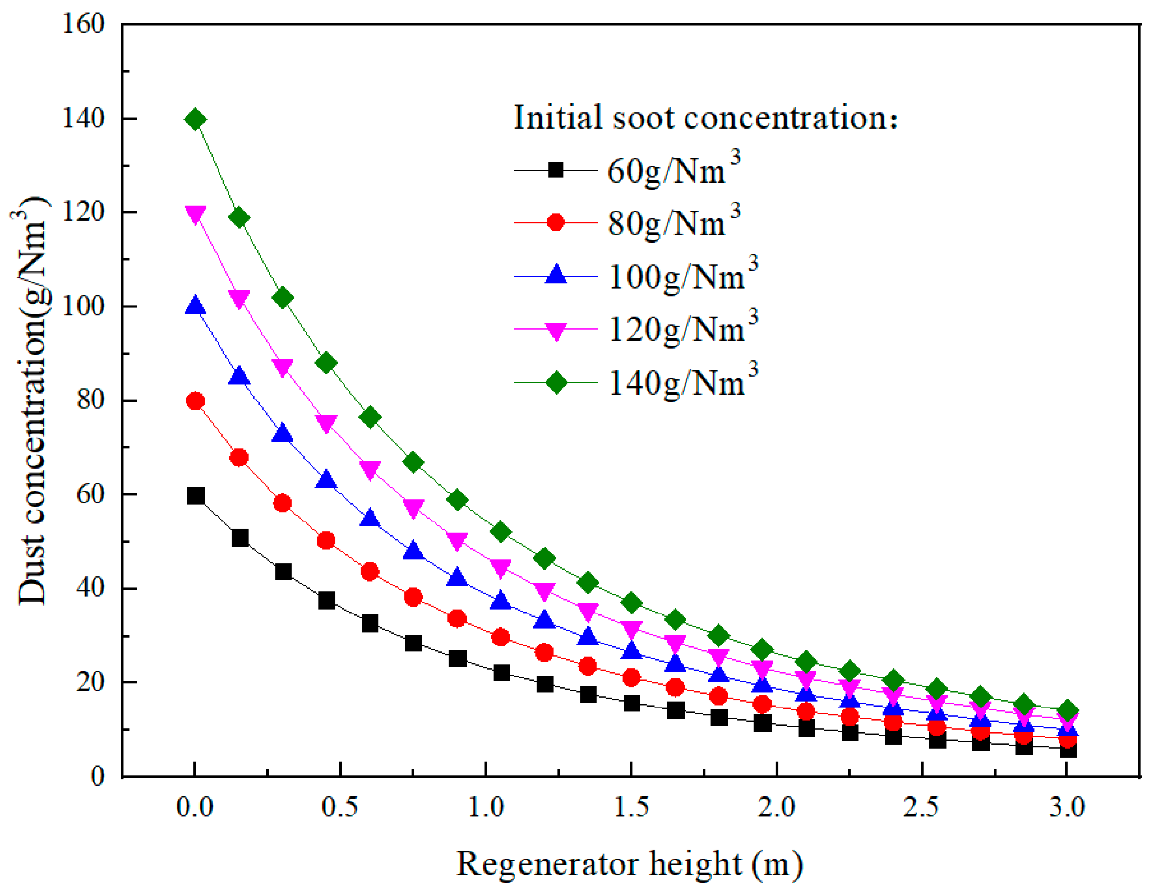
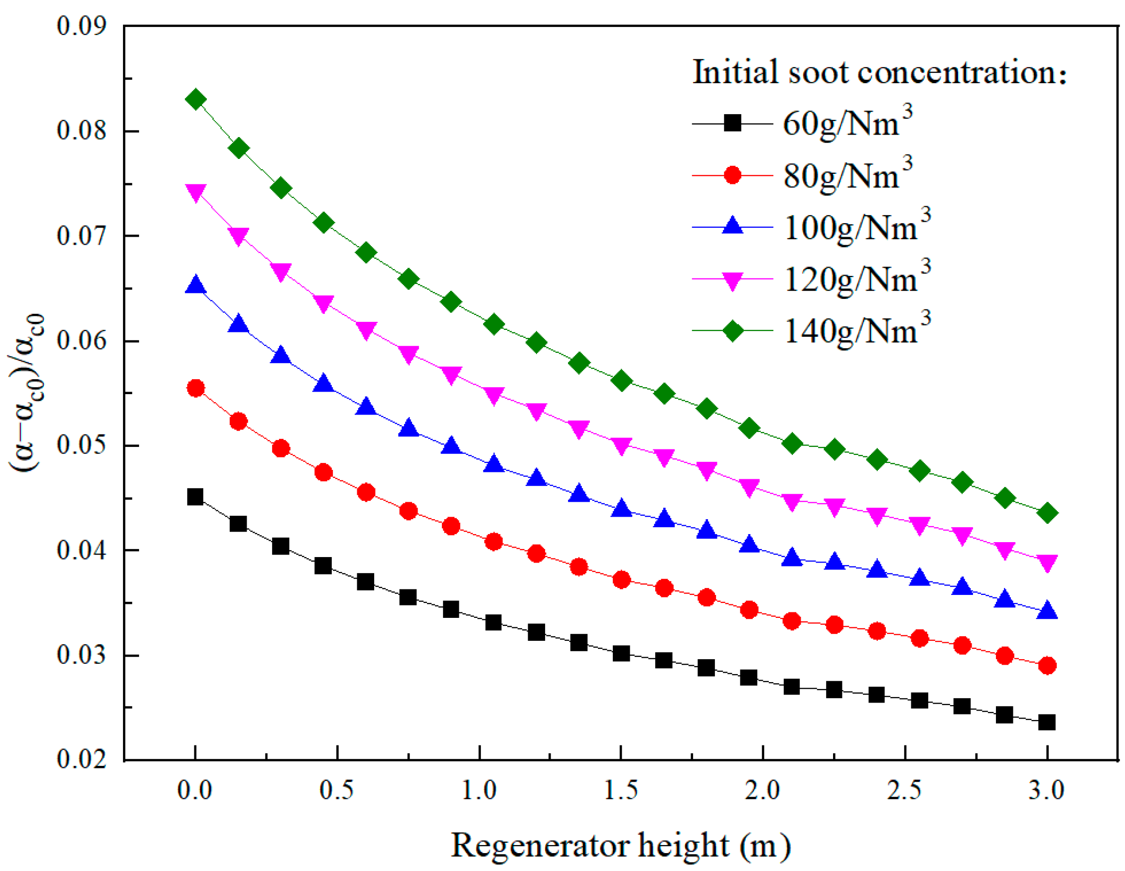
3.2. Effect of Initial Soot Concentration on Gas Phase Heat Transfer and Dust Removal Efficiency
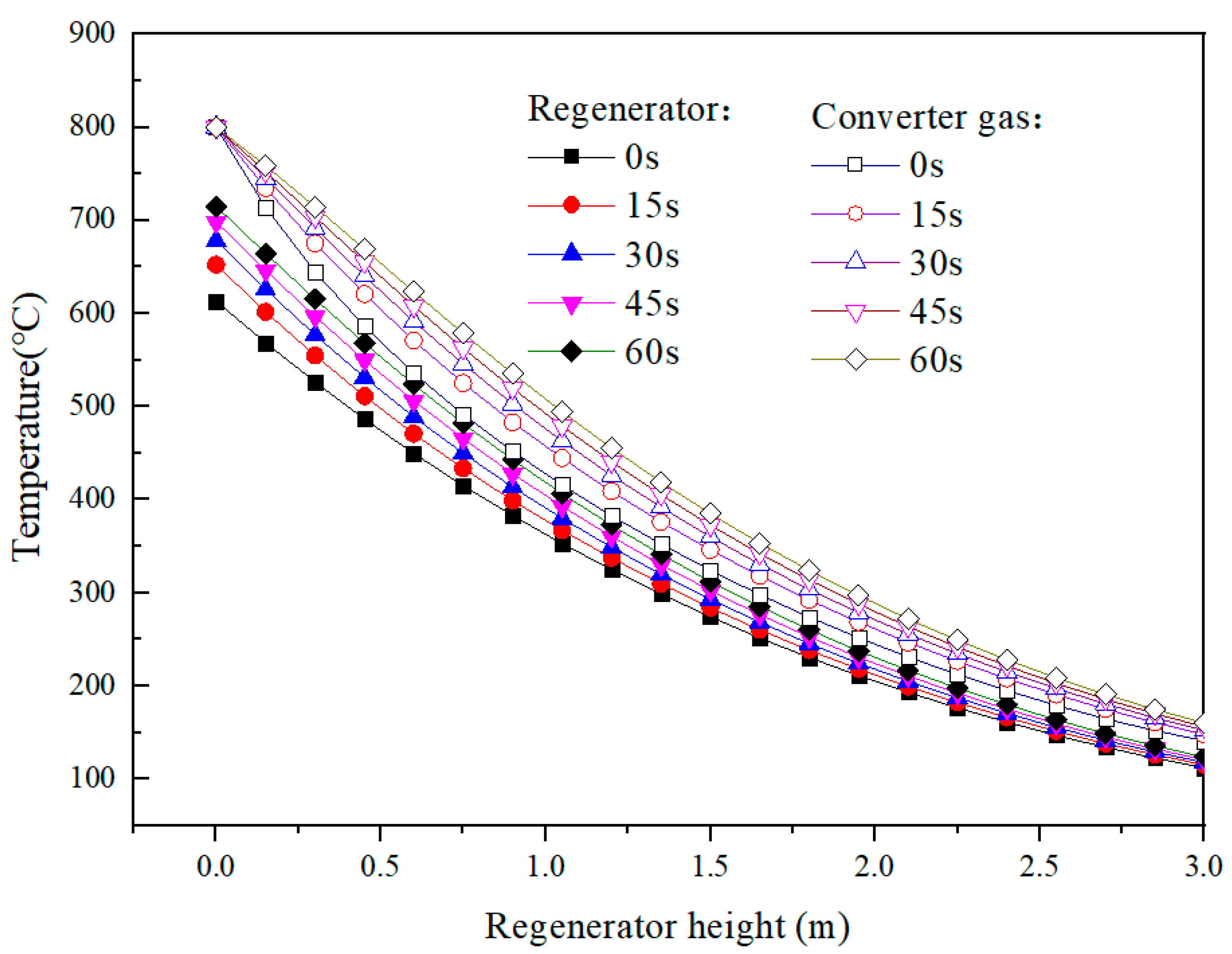
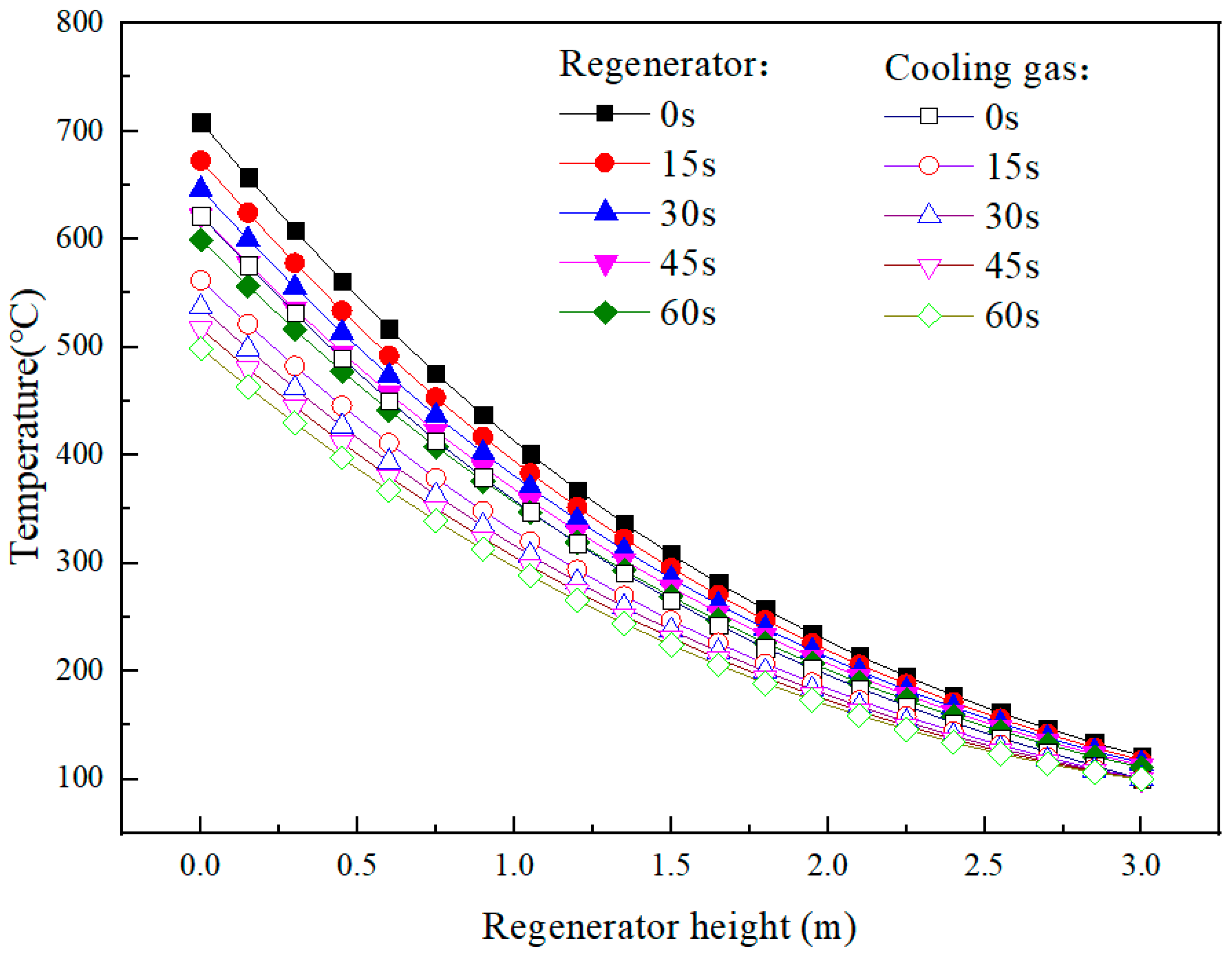
3.3. Heat Transfer and Flow in the Regenerator in a Commutation Cycle
4. Conclusions
- (1)
- Smoke and dust strengthen the heat transfer process in the regenerator. With the increase in soot particle size, the enhancement of the heat transfer process is weakened, and the dust removal efficiency is increased.
- (2)
- With the increase in the initial concentration of soot particles, the enhancement of the heat transfer process is strengthened, and the dust removal efficiency is reduced. At the entrance of the regenerator, the strengthening effect of smoke and dust is the strongest, and the heat transfer coefficient increases by 4.5–8.5%.
- (3)
- In a reversing cycle, the temperature of converter gas can be reduced to about 132 °C after flowing through the regenerator, and the dust removal efficiency in the regenerator can reach 90%.
- (4)
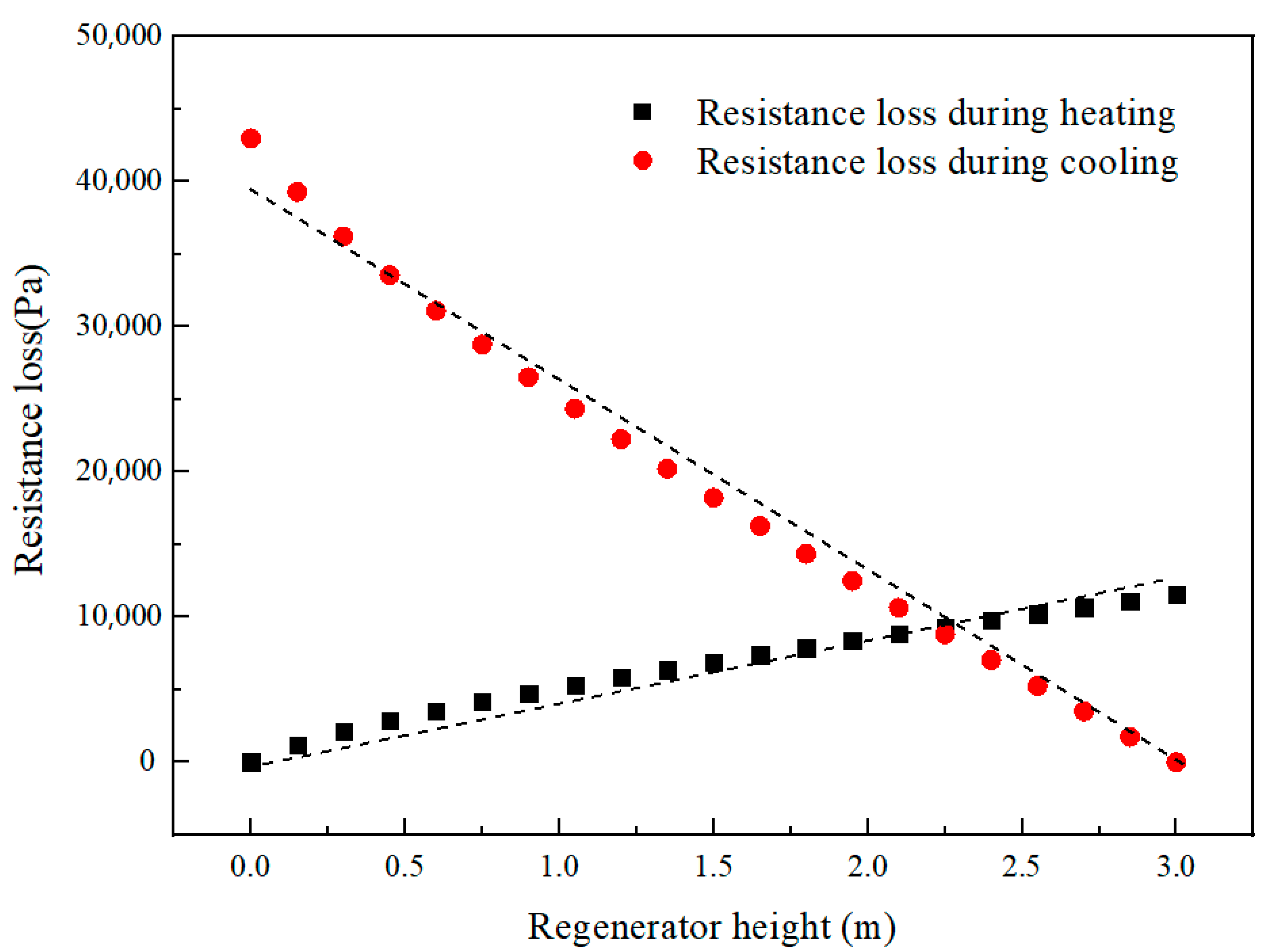
- The existence of smoke and dust in gas increases the resistance loss in the regenerator, and the resistance loss increases by about 25%. Moreover, due to the high smoke concentration at 0–0.7 m in the regenerator, the change speed of resistance loss is greater than that in other parts.
Author Contributions
Funding
Institutional Review Board Statement
Informed Consent Statement
Data Availability Statement
Acknowledgments
Conflicts of Interest
Nomenclature
| Wf | gas flow | m3/s |
| Cf | specific heat of gas | J/(m3·°C) |
| A0 | sectional area of regenerator | m2 |
| α | coefficient of convective heat transfer | W/(m2·°C) |
| tf | temperature of gas | °C |
| tm | temperature of filled ball | °C |
| a | specific surface area | m2/m3 |
| Cd | specific heat of smoke and dust | J/(kg·°C) |
| M1(x) | mass flow of smoke and dust in the gas in the heating period | kg/s |
| M2(x) | mass flow of smoke and dust in the gas in the cooling period | kg/s |
| β | dust content of flue gas | g/m3 |
| Wf0 | gas volume flow at inlet | m3/s |
| Cm | specific heat of filled ball | J/(kg·°C) |
| ρm | sphere density of filled ball | kg/m3 |
| ε | regenerator porosity | |
| thermal conductivity of filled ball | W/(m·K) | |
| time | s | |
| x | coordinates of height direction in regenerator | m |
| H | regenerator height | m |
| P | cycle time of commutation | s |
| dust removal efficiency passing through the N-layer regenerator layer | ||
| the dust removal efficiency of single-layer regenerator | ||
| the dust removal efficiency of isolated sphere | ||
| the interception efficiency | ||
| the inertial collision efficiency | ||
| the diffusion efficiency | ||
| heat transfer coefficients of multiphase flow | W/(m2·°C) | |
| heat transfer coefficients of pure gas flow | W/(m2·°C) | |
| dps | the particle size of dust particles | mm |
| resistance loss | Pa | |
| dynamic viscosity of gas | Pa·s | |
| gas density | kg/m3 | |
| constant | 229 | |
| constant | 1.96 | |
| 1 | heating period | |
| 2 | cooling period |
References
- Cai, N.; Qiu, G.; Liu, Y.; Ge, B.; Liu, Z.; Zhang, H. Purification and recovery technology of converter gas and its application. Metall. Energy 2017, 36, 98–101. [Google Scholar]
- Yuan, C. Experimental study on explosion of converts gas. J. Northeast. Univ. (Nat. Sci.) 2009, 30, 265–268. [Google Scholar]
- Shang, R.; Li, G.; Yu, L.; Dong, M. Experimental study on ignition of converter gas by high temperature particles. J. Northeast. Univ. (Nat. Sci.) 2015, 36, 1342–1346. [Google Scholar]
- Steinparzer, T.; Haider, M.; Zauner, F.; Enickl, G.; Michele-Naussed, M.; Horn, A.C. Electric arc furnace off-gas heat recovery and experience with a testing plant. Steel Res. Int. 2014, 85, 519–526. [Google Scholar] [CrossRef]
- Du, W.; Wang, Y.; Liang, X. System assessment of carbon dioxide used as gas oxidant and voolant in vanadium-extraction converter. JOM 2017, 69, 1785–1789. [Google Scholar] [CrossRef]
- Wang, B.; Zhou, J.; Xie, J.; Liu, Z.; Zhang, H.; Zhou, L. Numerical and experimental investigations of converter gas improvement inside a flue using its waste heat and CO 2by pulverized coal injection. Environ. Prog. Sustain. Energy 2018, 37, 1503–1512. [Google Scholar] [CrossRef]
- Zhou, J.; Jiang, X.; Xie, J.; Zhang, H.; Li, L.; Wang, B.; Ni, H. Thermodynamic analysis of improvement of converter gas by injecting pulverized coal into vaporization cooling flue. J. Iron Steel Res. Int. 2018, 25, 65–71. [Google Scholar] [CrossRef]
- Wu, Y.; Luo, C.; Wei, L.; Zhu, T.; Su, Q. Utilization of converter off-gas based on chemical-looping combustion. CIESC J. 2019, 70, 1923–1931. [Google Scholar] [CrossRef]
- Spalding, D. A theory of inflammability limits and flame-quenching. Proc. R. Soc. Lond. Ser. A Math. Phys. Sci. 1957, 240, 83–100. [Google Scholar]
- Ciccarelli, G. Explosion propagation in inert porous media. Philos. Trans. R. Soc. A Math. Phys. Eng. Sci. 2012, 370, 646–667. [Google Scholar] [CrossRef] [Green Version]
- Qin, Q.; Wang, K.; Yu, Q.; Fang, L. Feasibility study on recovery of converter gas waste heat by honeycomb regenerator. J. Northeast Univ. (Nat. Sci.) 2018, 39, 1608–1613. [Google Scholar]
- Khan, J.; Beasley, D. Two-dimensional effects on the response of packed bed regenerators. Trans. ASME J. Heat Transfer. 1989, 111, 328–336. [Google Scholar] [CrossRef]
- Shen, L.; Gao, X.; Cen, K. Heat transfer of tubes in gas-solid cross flow. Proc. CSEE 1996, 16, 400–405. [Google Scholar]
- Willmott, A.J. Digital computer simulation of a thermal regenerator. Heat Mass Transf. 1964, 7, 1291–1302. [Google Scholar] [CrossRef]
- Chi-Hsiung, L.; Finalayson, B. Heat transfer in packed beds-A reevaluation. Chem. Eng. Prog. 1977, 32, 1055–1066. [Google Scholar]
- Rajagopalan, R.; Tien, C. The theory of deep bed filtration. Prog. Filtr. Sep. 1979, 1, 179–269. [Google Scholar]
- Ergun, S. Fluid flow through packed columns. Chem. Eng. Prog. 1952, 48, 89–94. [Google Scholar]

Disclaimer/Publisher’s Note: The statements, opinions and data contained in all publications are solely those of the individual author(s) and contributor(s) and not of MDPI and/or the editor(s). MDPI and/or the editor(s) disclaim responsibility for any injury to people or property resulting from any ideas, methods, instructions or products referred to in the content. |
© 2023 by the authors. Licensee MDPI, Basel, Switzerland. This article is an open access article distributed under the terms and conditions of the Creative Commons Attribution (CC BY) license (https://creativecommons.org/licenses/by/4.0/).
Share and Cite
Zuo, Z.; Dong, X.; Luo, S.; Yu, Q. Waste Heat Recovery from Converter Gas by a Filled Bulb Regenerator: Heat Transfer Characteristics. Processes 2023, 11, 915. https://doi.org/10.3390/pr11030915
Zuo Z, Dong X, Luo S, Yu Q. Waste Heat Recovery from Converter Gas by a Filled Bulb Regenerator: Heat Transfer Characteristics. Processes. 2023; 11(3):915. https://doi.org/10.3390/pr11030915
Chicago/Turabian StyleZuo, Zongliang, Xinjiang Dong, Siyi Luo, and Qingbo Yu. 2023. "Waste Heat Recovery from Converter Gas by a Filled Bulb Regenerator: Heat Transfer Characteristics" Processes 11, no. 3: 915. https://doi.org/10.3390/pr11030915