Article

Reasonable Support Technology of Full-Stress Anchoring Technology of Advance Roadway: A Case Study

State Key Laboratory of Coal Resources and Safe Mining, School of Mines, China University of Mining and Technology, Xuzhou 221116, China
*
Authors to whom correspondence should be addressed.
Processes 2023, 11(4), 1052; https://doi.org/10.3390/pr11041052
Submission received: 28 February 2023 / Revised: 23 March 2023 / Accepted: 28 March 2023 / Published: 31 March 2023

Abstract

:
Based on the engineering background of providing advance support for the working face of mining roadways, this paper studies the reasonable support technology of advance roadway roofs by combining theoretical analysis, numerical simulation, and field tests. Based on the geological conditions of the 1304 working face of Yineng Coal Mine, the FLAC3D numerical simulation software was used to compare and analyze the effects of the original single hydraulic prop advance support and the bolt-mesh-cable support without the single hydraulic prop. The results show that although the deformation of the surrounding rock is reduced under the support of the single hydraulic prop, the convergence of the roof and floor of the roadway and the left and right sides are still as high as 288 mm and 308 mm, respectively, which does not meet the requirements for safe production. Based on this problem, this study proposes full-stress anchoring technology. FLAC3D numerical simulation software is used to simulate and analyze the supporting effect of the full-stress anchoring support technology in advanced mining roadways. The results of numerical simulation experiments show that the convergence of the roof and floor and the convergence of the left and right sides of the roadway surrounding rock are 33 mm and 52 mm, respectively, which have a good control effect on the roadway surrounding rock. The field test of bolt full-stress anchoring support technology was carried out in the return air roadway of the 1304 working face. The deformation of the surrounding rock of the roadway was monitored by setting up stations. The measured results show that the maximum roof and floor convergence of the roadway is 42 mm, and the maximum convergence of the two sides of the roadway is 69 mm, which meets the requirements for safe mining on site. In this study, by comparing with the advance support effect of the original single hydraulic prop, the rationality of the full-stress anchoring technology of the mining roadway in the advance section of the working panel is determined. The use of bolt full-stress anchoring instead of the traditional single hydraulic prop for advanced support has a better surrounding rock control effect and a lower support cost. This is a new technology for advanced support of surrounding rock in mining roadways, which enriches the control technology of roadway surrounding rock and also provides technical reference for other similar engineering cases.

1. Introduction

According to incomplete statistics, based on the 2014–2022 National Mine Safety Administration National Coal Mine Accident Analysis Report and related literature statistics, mine roof disaster accidents accounted for 34.7% of the total number of coal mine safety accidents, and the number of deaths accounted for 28.4% of the total number of deaths in coal mine accidents [1,2,3,4]. Coal mine roof accidents have become the first disaster in coal mine safety production, as shown in Table 1. In the roof accidents, half of the accidents occurred at the upper and lower safety exits and in the advanced support work. As a roadway serving the coal mining face, the mining roadway is mainly responsible for coal transportation, mining face ventilation, and other tasks [5,6,7]. However, most of the mining roadways are coal roadways, and their surrounding rock joints have been developed with poor integrity and low strength. The section of the mining roadway near the coal mining face is prone to roof fall in this section due to the influence of mining on the coal mining face.
Due to the influence of mining stress and tectonic stress, the advance abutment pressure will be generated in front of the working panel during mining, which makes the roof pressure of the mining roadway in the advance section of the working panel more prominent, which is manifested as roof deformation and subsidence, coal wall spalling, roadway floor heave, and so on. In order to effectively solve such phenomena in the mining roadway during the mining of the working face, advanced support has become a common solution [8,9,10,11]. The advance support ensures the stability of the safe exit above and below the working panel. Before the first collapse of the main roof, the “beam” structure is formed, and the weight of the overlying strata is transmitted to the coal wall of the working panel and the rear coal pillar through the “beam structure.” The basic roof collapse is distributed as a masonry beam. Regardless of the form of distribution, the resulting advance abutment pressure will cause the solid coal pillar to withstand greater pressure. If effective advance support measures cannot be taken, it is easy to cause damage to the solid coal pillar, and the broken coal body will block the upper and lower safety exits of the working face, affecting safe production. Therefore, in order to ensure the safe production environment of the working face, it is necessary to strengthen the support of the advance section of the mining roadway.
At present, the reinforcement support of the advance section of the mining roadway in the working panel adopts the passive support form based on the single hydraulic prop and the advance hydraulic support [12,13,14,15]. The single hydraulic prop is often equipped with a hinged top beam (one or cross beam) for advanced support. The support form is “point” support, the support strength is small, and the manual handling method is adopted. The support process involves two steps: “support” and “return column.” In order to improve the ability to adapt to roof deformation, the stroke of the single hydraulic prop is usually required to be not less than 200 mm. In the process of supporting the mine, attention should be paid to the mining height. According to the section size and form of the mining roadway in the working face and the distribution and size of the roof pressure in the section, reasonable support forms and parameters should be designed to ensure the rationality of the support scheme and the safety of the upper and lower safety exits. Because the support effect of the single hydraulic prop is greatly affected by the relationship between the pillar cap and the roof, and because there are problems such as high labor intensity, a small supporting section, low supporting strength, and poor stability, it is easy to cause safety accidents. The general design method of hydraulic support for advanced support of the mining roadway in common mines is that the top beam, front beam or telescopic beam, and guard plate are supported separately, and each top beam is connected by adjusting jacks [16,17,18,19,20,21]. The support is adjusted by a single prop or single jack cylinder to realize the support of the roadway roof. Although the advanced hydraulic support effectively improves the stability of the surrounding rock of the roof in the advanced section, due to the large range of roof control and the need to repeatedly support and shrink the roof, it is easy to cause the roof to break and leak, aggravate the shrinkage of the roadway section, and produce safety problems such as wind speed overrun. Wooden props and cribs can also be used for advanced support of roadways. In the early stages of the development of China’s coal industry, wooden props and wooden cribs were the main means of underground support for coal mining in China. However, the recovery of wooden props and wooden cribs is difficult. Most of them are disposable, and the consumption of wood is huge [22]. Steel cylinders filled with binder can be used for advanced support of roadways and strengthening support of roadways affected by dynamic pressure. In addition to the steel cylinders, the constraint material on the surface of the prop can also use steel wire, fiber hoop, or tin in order to increase the strength and stability of the pillar. However, this method makes it difficult to transport materials, and the construction process is complicated [23].
As an active support method, bolt support has the characteristics of high support strength, high flexibility, and low cost and is widely used in coal roadway roof support. In the whole bolt support system of the coal mine roadway, the bolt is anchored into the surrounding rock of the roadway, and the physical characteristics of the anchored surrounding rock are improved while the overall strength is improved [24,25,26]. Bolt support gives full play to the self-stabilization ability of the roadway surrounding rock and improves its strength, effectively controls the deformation and failure of the anchored surrounding rock, maintains the long-term stability of the roadway, plays an important bearing role in the whole roadway support system, and is the foundation of the whole support system. The process of creating bolt support for the roof of a coal roadway is as follows: drilling rig, cleaning drilling cuttings, loading anchoring agent, inserting bolt, stirring, anchoring agent condensation, and then tensioning bolt. According to the existing literature, the transmission of the anchoring force of the bolt and the distribution of the effective compressive stress zone of the surrounding rock under this anchoring method are not good, and the control of the surrounding rock by the bolt is insufficient, resulting in the emergence of invalid anchoring sections and even anchoring failure [27,28,29,30,31,32]. The existing bolt support theory and technology cannot effectively solve the control problem of the roadway surrounding rock under complex conditions and cannot effectively control the roof surrounding rock of an advanced roadway. At present, it is urgent to seek a breakthrough in the new support theory and technology so as to realize effective control of the surrounding rock in the advance section of the roadway and reduce the cost of roadway support.
Many scholars have carried out relevant research on improving the prestressed anchorage effect of bolts. Kang Hongpu [33,34] believes that it is an effective method for improving the effect of bolt support by applying greater prestress to the bolt and realizing the diffusion of prestress through the components such as the supporting plate and steel strip. Based on the strength strengthening mechanism of surrounding rock, Hou Chaojiong [35] discussed the response mechanism of microscopic damage and fracture evolution scale of surrounding rock in the process of macroscopic surrounding rock failure, expounded the synergistic control effect of deep and shallow progressive layered grouting on surrounding rock of deep roadways, and established the quantitative interval of macroscopic damage and microscopic fracture evolution of surrounding rock under the conditions of prestress, full-length anchorage, and timely support. Zhang Nong [36] believed that there was a critical time point for the empty roof support after roadway excavation, and the time-dependent self-stability characteristics of the end should be fully utilized to construct the stable rock beam of the roof in time, so as to achieve the effect of two-way continuous and two-state continuous and realize the small mine pressure, micro-deformation, and low damage of the roof. Krykovskyi [37] proposed that the position of the bolt is crucial to the formation of the rock-bolt arch. After the grouting bolt is installed on the roof of the mine roadway, the interaction between the bolts will be formed, and the integral arch structure with high integrity can be formed inside the roof of the working panel. The integral arch structure can control the unstable rock strata inside the roadway roof, reduce the deformation of the surrounding rock of the roadway, and reduce the water inflow and gas release from the surrounding rock. Rehman [38] studied the supporting performance of tunnel support systems under different lithology conditions. Bolt support was carried out on the roadway section, and the support effect was numerically analyzed by using the 2D elasto-plastic finite element method (FEM). In the area with poor rock quality, the surrounding rock is easy to deform and yield, especially the vault. The corresponding method is to lengthen the anchor support length, and the anchor length should not be less than 5 m. Ghazdali [39] analyzed and determined the mining design of shallow-dip deposits in poor rock masses, and bolted the rock strata of the stope. The numerical simulation experiment of the unstable zone width and the maximum displacement law of the surrounding rock under various rock strata and technical conditions was carried out by RS2 software. Through the experiment, the position of the stable area of the surrounding rock of the stope is determined, the surrounding rock control of the shallowly buried inferior rock layer is realized by anchoring the bolt in the stable area of the surrounding rock, and the optimal mining design method of the shallow mining is revealed.
There are also many studies on the distribution law of anchor stress. Yin et al. [40] studied the evolution law of stress distribution in anchorage sections and its influencing factors by combining laboratory tests with mesoscopic particle flow simulation. It is considered that the elastic modulus of the bolt and anchorage agent affects the distribution of axial force and interfacial shear stress of the bolt. The larger the elastic modulus of the bolt, the smaller the elastic modulus of the anchoring agent, resulting in a smaller concentration of shear stress at the pull-out end of the anchoring section. Zheng Xigui et al. [41,42,43] used MATLAB numerical calculation software to calculate the distribution of prestress in surrounding rock under different anchorage modes, surrounding rock properties, bolt diameter, and preload. The results show that under different anchorage modes, the distribution of prestress is basically the same, but the range of action is different. Extending the anchorage mode can increase the range of action of prestress. The effect of prestressed anchorage in soft rock is better than that in hard rock. Increasing the diameter of the bolt can improve the propagation effect of the anchoring force in the surrounding rock. Increasing the pre-tightening force cannot change the pre-stress diffusion range of the anchorage section, but it can increase the peak stress and the compressive stress of the surrounding rock near the orifice, which has a good effect on improving the stress state of the surface surrounding rock. Wang Hongtao et al. [44] considered and analyzed the influencing factors such as bolt diameter, surrounding rock strength parameters, anchorage length, preload, and layout spacing, and established a mechanical analysis model of roadway surrounding rock under different anchorage lengths. The results show that the stress of the bolt is mainly concentrated in the range of 1/3 of the end of the anchorage section, and the shear stress and axial force of the bolt are decreasing along the length direction. Applying high pre-tightening force and setting a certain length of free section is conducive to the diffusion of bolt pre-tightening force in surrounding rock, which can form an effective bearing structure for anchoring surrounding rock and give full play to the potential of rod support. When the bolt spacing is large, the control effect of pre-tightening force on surrounding rock can be increased by increasing the pre-tightening force and appropriately reducing the anchorage length.
Relevant scholars have paid attention to the phenomenon of bolt anchorage failure and put forward their own views on its causes. Zhao Tongbin et al. [45] tested the axial shear stress law between the bolt body and the mortar bonding interface through the indoor pull-out test of the full-length anchored mortar bolt. The results show that the shear stress increases first and then decreases gradually along the axial direction of the bolt, with the maximum value near the drawing port. Along the radial direction of the bolt, as the distance increases, the shear stress decreases according to the negative exponential function. The change in bonding parameters will lead to different types of bolt reinforcement failure. Krzysztof Skrzypkowski [31] fixed the 2.2 m anchor rod with different anchoring lengths by using a hydraulic pump. The experimental anchor rods were embedded at 0.05 m, 0.3 m, and 0.9 m, respectively. In order to fix the anchor in the steel pipe, a 0.45-meter-long resin anchoring agent was used. This study determined the load-displacement characteristics between the bolt and the anchorage body, determined the failure point of the bolt, and determined the stress-strain characteristics on this basis. Li Huaizhen et al. [46,47,48] studied the influence of different boundary constraints on the bearing characteristics of the anchorage section of the bolt. The research shows that the axial force of the bolt of the anchorage specimen with different boundary constraints decreases along the anchorage length, and the axial force of the bolt of the anchorage specimen with lateral constraints decreases faster than that of the specimen without lateral constraints. The distribution law and peak position of the shear stress at the interface of the bolt-anchoring agent under different boundary constraints are obviously different. The bolt needs to take different anchoring failure prevention measures at different times of tension preloading and coordinated deformation of the bolt-surrounding rock.
The predecessors have carried out a large number of experiments and engineering case studies on the load transfer mechanism and technology of the pre-stressed bolt anchorage section, which has promoted the application research of the bolt in the surrounding rock control of the coal mine roadway and also provided theoretical and technical reference for the bolt support roadway roof surrounding rock in the advance section of the working panel. However, because the surrounding rock of the mining roadway in the advance section of the working panel needs to bear the advance support pressure, compared with the roadway with less stress concentration, there are higher standard requirements for the bolt support effect in the mining roadway support in the advance section of the working panel. However, under the existing bolt support theory and technology, the stress distribution of the bolt is mainly concentrated in the top area of the anchorage. The range of stress transmission is small, and the stress value attenuates rapidly along the length direction of the bolt. Due to the above situation, the effect of the bolt on surrounding rock control is mainly reflected in the anchoring force at the end of the anchoring section and the anchoring force at the tray position, but the surrounding rock in the middle part has not been effectively supported by stress. When encountering the relatively broken rock strata inside the surrounding rock, it is often due to the lack of rock support between the end and the tail of the bolt, resulting in problems such as rock separation, roof fall, and rib spalling. This is the limitation of current research. Therefore, for the existing bolt support theory and technology, there is still room for improvement in improving the load transfer range of the bolt anchorage section and the prestress distribution effect of the anchorage zone.
Therefore, in this paper, the research on reasonable support technology for full-stress anchoring for advanced roadway roofs in a longwall mining face is carried out. Combined with the engineering case of the Yineng Coal Mine, the effect of the original single hydraulic prop advance support scheme was analyzed and evaluated. The supporting effects of the two methods of “bolt-mesh-cable + single hydraulic prop” and “bolt-mesh-cable” advanced support are compared and analyzed. The advanced support technology of full-stress anchoring instead of the single hydraulic prop is proposed. The support parameters are optimized, and the support design is carried out. The numerical simulation study on the advanced support scheme of full-stress anchoring is carried out. The results show that the control effect of bolt full-stress anchoring on the surrounding rock of the mining roadway in advance section of working panel is better than that of the single hydraulic prop support. It is reasonable to use bolt full-stress anchoring to support the roofs of mining roadways in an advance section of working panel, which is of great significance for the safe and efficient production of coal mines.

2. Engineering Status of the 1304 Working Face Study Area

2.1. Lithology of the Roadway Roof and Floor

There are three layers of mineable coal seams in the Yineng Coal Mine: No. 3, No. 16, and No. 17. This study mainly involves the No. 3 coal seam. The ground elevation of the minefield is about +45 m, the horizontal elevation of the No. 3 coal seam mining is about −725 m, the coal seam thickness range is 1.2–4.6 m, the average coal thickness is about 3.8 m, the buried depth is about 770 m, the coal seam dip angle is between 6° and 8°, with an average of 7°, which is a nearly horizontal thick coal seam. The direct roof of the No. 3 coal seam is generally medium and fine sandstone, and the direct floor is generally mudstone and fine sandstone. Core sampling was carried out in the advanced section of the 1304 working face. After measurement and lithology analysis, the columnar diagram of roof and floor conditions of the No. 3 coal seam is shown in Figure 1.

2.2. Roadway Layout

The cross section of the transport roadway is shown in the working panel: the cross section of the transport roadway in the 1304 working face is designed as a rectangular section, with a net height of 3400 mm, a tunneling height of 3500 mm, a net width of 3900 mm, and a tunneling width of 4000 mm. The form of advance support: the advance support of the transportation roadway is 20 m, and the double wedge hinged top beam support with three rows of single hydraulic props and DJB-1000/300(s) is adopted.
The roadway section of the return airway in the working panel: the section of the return airway in the 1304 working face is designed as a rectangular section, with a net width of 3800 mm and a tunneling width of 4000 mm. The form of advance support: the advance support of the return air roadway is 20 m, and the double wedge hinged roof beam support with three rows of single hydraulic props and DJB-1000/300 (s) is adopted.
The working face open-off cut: the open-off cut is 80 m long. Other roadways: transportation and return airways are respectively equipped with avoidance chambers, and temporary water storage is set up in low-lying areas.

2.3. Original Support Scheme and Effect

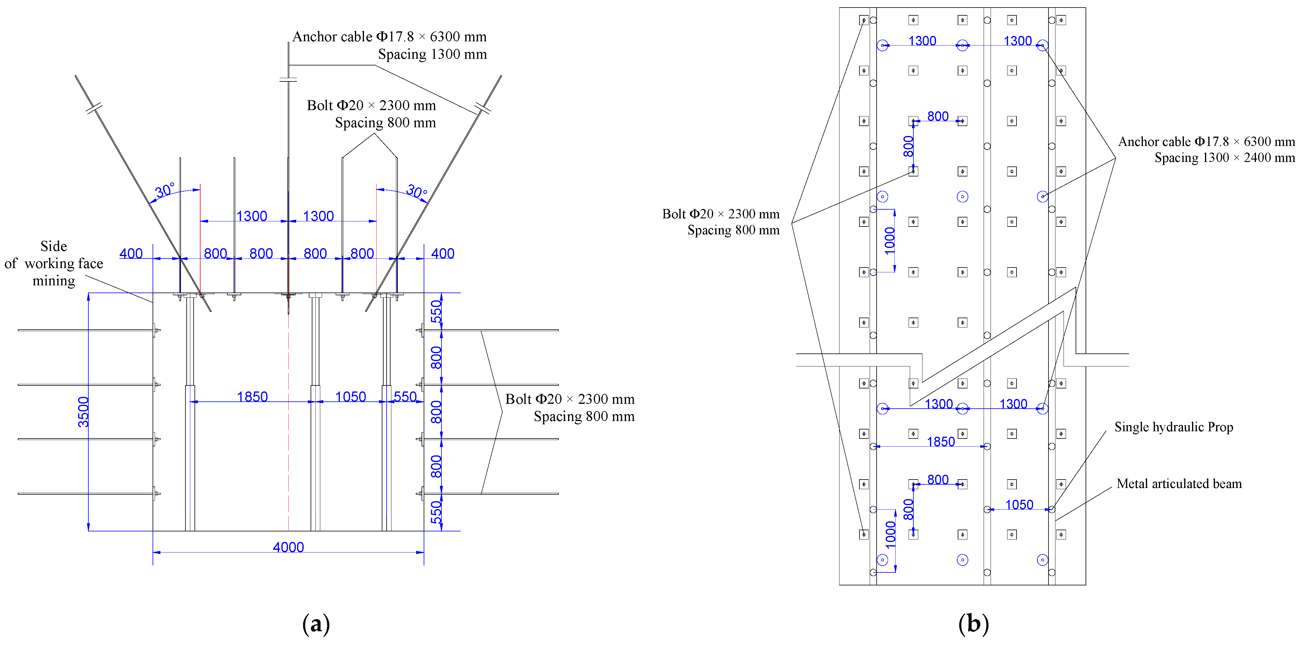
2.3.1. Original Support Scheme

Three rows of DW38-250/110X single hydraulic props and DJB-1000/300(s) hinged roof beams are used to support the roof in the 20 m range of the advance section of the transportation roadway and the return airway. The advanced support of the return airway in the section: the advanced support is carried out from the coal wall line forward 50 m, and the single hydraulic prop is supported in 3 rows. The first row of single hydraulic props is 0.55 m away from the coal pillar side of the working panel, and the column distance is 1.0 m. The middle row is 1.85 m from the first row, and the column spacing is 1.0 m. The other side is 0.55 m away from the coal body (goaf), and the column spacing is 1.0 m. The advanced support of the transportation roadway in the section: the advanced support is carried out 20 m forward from the coal wall line, and the single hydraulic prop is supported in 3 rows. The first row of single hydraulic props is 0.6 m away from the coal pillar side of the working panel, and the column distance is 1.0 m. The middle row is 3.3 m from the first row, and the column spacing is 1.0 m. The other side is 0.6 m away from the coal body (goaf), and the column spacing is 1.0 m.
The top support bolt adopts Φ20 × 2300 mm left-handed, non-longitudinal, reinforced screw-threaded steel bolt. The bolt is arranged in a rectangular arrangement with an interval of 800 × 800 mm, and the top is covered with 100 × 100 mm wire mesh. The support of the side adopts Φ20 × 2300 mm equal-left-handed non-longitudinal rebar bolts, and 100 × 100 mm wire mesh is laid. The bolts are arranged in a rectangular arrangement, and the spacing is 800 × 800 mm. The bolts were anchored with two CK2350 anchoring agents, and the preload was 80 kN.
The anchor cable is cut by a Φ17.8 mm low relaxation prestressed steel strand with a length of 6300 mm. The anchor cable tray adopts a specially processed circular tray with a diameter of 250 mm. A Φ20 mm hole is drilled in the middle, and each anchor cable has an anchor cable tray. Each anchor cable uses two CK2350 anchoring agents for end anchoring. The anchoring force is 92 kN, the preload is not less than 28 MPa, and the exposed length is 150–250 mm. The roof of the return airway of the 1304 working face is a composite layered roof, which is prone to interlayer shear dislocation, and the anchor cable is prone to fracture failure at the shear stress concentration of the two sides of the roof. Based on a large number of engineering practices, the installation angle of anchor cable is generally 15–30°. When the installation angle of anchor cable is 30°, the section of anchor cable under shear action increases, which can increase the shear resistance of anchor cable. In addition, the corner anchor cable makes a large compressive stress zone between the surrounding rock in the roadway in the corner direction and the anchor cable supporting the vertical roof. At the same time, the anchor cable plays a suspension role to avoid the problem that the surrounding rock in the deep corner of the roadway roof cannot be effectively supported, resulting in the destruction of the roadway roof from the corner position and causing the roof to cut off. The advance support form of the 1304 working face return airway is similar to that of the transportation roadway. The 1304 working face return airway is selected as the research object. The advance support scheme of the 1304 working face return airway is shown in Figure 2.

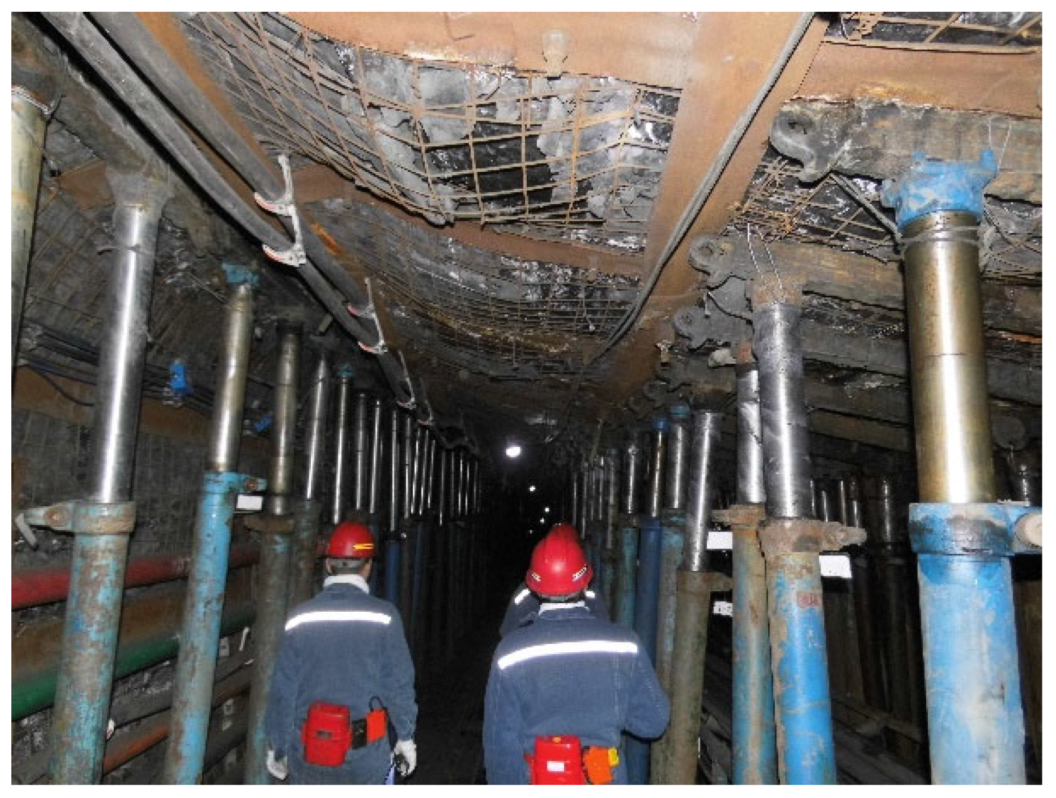
2.3.2. Effect and Analysis of Original Support

The original scheme uses a single hydraulic prop to advance the support of the return airway of the 1304 working face, as shown in Figure 3. When the 1304 working face is mined, the deformation of the surrounding rock of the return airway in the advance section of the working panel is enhanced, showing the phenomenon of roof subsidence, loosening, and collapse of the surrounding rock on the roof surface, and the failure of the bolt tray from the roof support, as shown in Figure 4.
According to the above analysis of the roadway deformation under the original single hydraulic prop advance support scheme, the existing problems are as follows:
(1)
The single hydraulic prop cannot achieve effective support of the roof.
Three rows of DW38-250/110X single hydraulic props are used to support the return airway of the 1304 working face in advance of 20 m. Under this support scheme, the maximum subsidence of the roadway roof is about 500 mm, and the convergence of the two sides is about 300 mm. The deformation of the roof and the side is serious and cannot meet the normal production requirements. Due to the increased advanced support stress of the mining roadway in the advanced section during the mining of the working face, the column leg of the single hydraulic prop is prone to the phenomenon of “drilling the bottom”, resulting in the reduction of the effective support strength, and the surrounding rock of the roadway roof is broken, forming a large number of “net pockets” and increasing the probability of a roadway “roof fall” accident. If the single hydraulic prop support method is continued, only the support row spacing can be further reduced, and the “one beam and multiple columns” support method can be used. However, the corresponding problem is that the column spacing between the single hydraulic props is reduced, resulting in an increase in the transportation and support workload of the single hydraulic support. At the same time, it is necessary to consider the anti-collapse and anti-skid measures of the prop before the prop, and the single hydraulic prop has a large amount of retraction, so the problem of no-load and support failure cannot be fundamentally solved. At the same time, due to the relatively broken roof, the contact support area between the single hydraulic prop and the roof needs to be further improved, and its adaptability to the roof condition is poor.
(2)
The anchoring force of the bolt on the roadway roof support is insufficient.
The bolt of Φ20 × 2300 mm left-handed non-longitudinal rebar is used to support the roof of the return airway in coordination with the single hydraulic prop. Due to the repeated action of advancing abutment stress, which gradually increased during the mining process of the working face, the roof sinks and causes the axial displacement of the bolt at the same time. The anchorage agent and the anchorage interface of the corresponding bolt anchorage section debond and slide, resulting in the loss of the anchoring force of the bolt and the insufficient anchoring force of the roadway roof support. At the same time, because the length of the bolt is only 2.3 m and the end of the bolt is anchored, the roof surface of the return airway of the 1304 working face is relatively broken. The range of the bolt prestress and the anchoring force on the roof of the roadway is shallow, and it mainly stays at the bolt tray and the end of the bolt. The middle anchorage section does not form an effective stress distribution. Therefore, the support method has a shallow support depth for the surrounding rock of the roadway roof, and the support effect is not good.

3. Numerical Simulation Study on the Supporting Effect of the Single Hydraulic Prop in the Original Scheme

3.1. Establish the Geological Model of Mining Roadway in Working Panel

In order to study the effect of advanced support of the mining roadway using the single hydraulic prop in the original scheme of the Yineng Coal Mine, the geological model of the mining roadway in the working panel was established using FLAC3D numerical simulation software. The roof of the mining roadway in the advance section of the working panel was supported by the single hydraulic prop, and the stress characteristics and deformation of the surrounding rock of the roadway under the single hydraulic prop support mode were analyzed.
Under the condition of ensuring the reliability of the simulation, in order to facilitate the establishment of the model to realize the simulation calculation and better study the stress and deformation of the surrounding rock and the supporting unit of the roadway, the assumptions are set as follows:
(1)
The surrounding rock of the mining roadway is all isotropic, homogeneous, and continuous.
(2)
The surrounding rock of the mining roadway has a completely elastic-plastic body, and the mechanical properties meet the Mohr–Coulomb criterion.
(3)
The influence of time on the properties of the model is not considered in this simulation.
In this study, the geological structure of the No. 3 coal seam in the Yineng Coal Mine is simple, and there is no strong tectonic stress in the mine field. Therefore, in the study, the generation of ground stress is mainly due to the self-weight stress of the overlying strata, and its size is calculated by the following formula:
σ v = γ H ,
σ h = λ σ v ,
100 H + 0.3 γ 1500 H + 0.5 ,
where: σv is the vertical stress, MPa; σh is horizontal stress, MPa; γ is the average bulk density of overlying strata, 25,000 N/m3; H is the vertical height from the top of the experimental model to the surface, m, 733 m; λ is the lateral pressure coefficient, according to the existing research results, when the formation depth is less than 1000 m, the variation range of λ satisfies Formula (3), and the range of λ is from 0.45 to 2.55. In this study, λ takes an average of 1.5. Substituting the data: σv = 18.33 MPa, σh = 27.50 MPa.
As shown in Figure 5, the mechanical parameters of the roof and floor strata of the No. 3 coal seam in the Yineng Coal Mine were measured by a SANS microcomputer-controlled electro-hydraulic servo pressure experimental machine. At the same time, the TS3866 distributed static resistance strain gauge was used in combination with the computer to monitor the whole process in real time. The uniaxial compressive strength, uniaxial tensile strength, and uniaxial shear strength of rock (coal) samples were measured. The test process is shown in Figure 6a–c. The lithologic characteristics and mechanical parameters of the roof and floor of the No. 3 coal seam in the Yineng Coal Mine are shown in Table 2.
When using FLAC3D software to calculate and simulate, the Mohr–Coulomb yield criterion is adopted. The elastic constants usually used are bulk modulus K (bulk) and shear modulus G (shear). Therefore, it is necessary to calculate the corresponding data in Table 2. The calculation formula is as follows:
K = E 3 ( 1 2 μ ) ,
G = E 2 ( 1 + μ ) .
Among them: E-elastic modulus, GPa; μ -Poisson ratio.
According to Equations (4) and (5), the physical and mechanical parameters of coal and rock mass needed for modeling in this simulation can be calculated accordingly, see Table 3 below.
Because the 1304 working face transportation roadway and return air roadway advance support form are similar, on the premise of ensuring the reliability of the simulation, in order to improve the efficiency and accuracy of the model operation, reduce the size of the whole model, increase the local area grid density, and select the working panel return air roadway as the research object, establish the return air roadway advance support model.
(1)
Creating blocks
The research object of this numerical simulation is the return airway of the Yineng coal mine working face. The section size of the transportation roadway is 4 m wide and 3.5 m high. It is generally considered that the model is not affected by the excavation of the roadway at a distance of 5 times the radius of the roadway from the center of the roadway. The model is 40 m long (X axis positive), 3 m wide (Y axis positive), and 35 m high (Z axis positive).
(2)
Boundary constraint
(1)
The upper boundary of the model is a free boundary condition, which is subjected to a uniform load on the surface. The uniform load is the self-weight stress of the overlying strata, that is, 18.33 MPa, and the horizontal boundary is subjected to horizontal stress, that is, 27.5 MPa.
(2)
The lower boundary of the model is a displacement constraint condition, even if there is no displacement in the vertical direction.
(3)
The horizontal displacement of the front and rear, left and right surfaces of the model is limited to 0, but the vertical direction is not limited; that is, the vertical direction can be displaced after the force is applied.
According to the set model conditions, the geological model of the transportation roadway project is shown in Figure 7.

3.2. Single Hydraulic Prop Advance Support Simulation Scheme

(1)
Simulation scheme description
On the basis of using bolt-mesh-cable support, the mining roadway is supported by the single hydraulic prop in advance. Through the four aspects of vertical stress, vertical displacement, horizontal displacement, and the plastic zone of the mining roadway, the effect of advanced support of the single hydraulic prop in the mining roadway is studied.
(2)
Structural unit description of simulated supporting materials
In FLAC3D software, the bolt and anchor cable are generally simulated by the Cable structural unit. The definition of this type of structural unit mainly involves the elastic modulus, tensile strength, cross-sectional area, bonding force of the anchoring agent per unit length, stiffness of the anchoring agent per unit length, perimeter of the peripheral borehole of the anchoring agent, internal friction angle, and so on. The single hydraulic prop is generally simulated by the Pile structural unit. The definition of this type of structural unit mainly involves the elastic modulus, Poisson’s ratio, cross-sectional area, cylinder diameter, normal stiffness, normal cohesion, and normal friction angle of the single hydraulic prop. The Shell structural unit is used to simulate the wire mesh laid on the roadway roof and roadway side.
(3)
Supporting material parameter table
The parameters of simulated supporting materials are shown in Table 4.
(4)
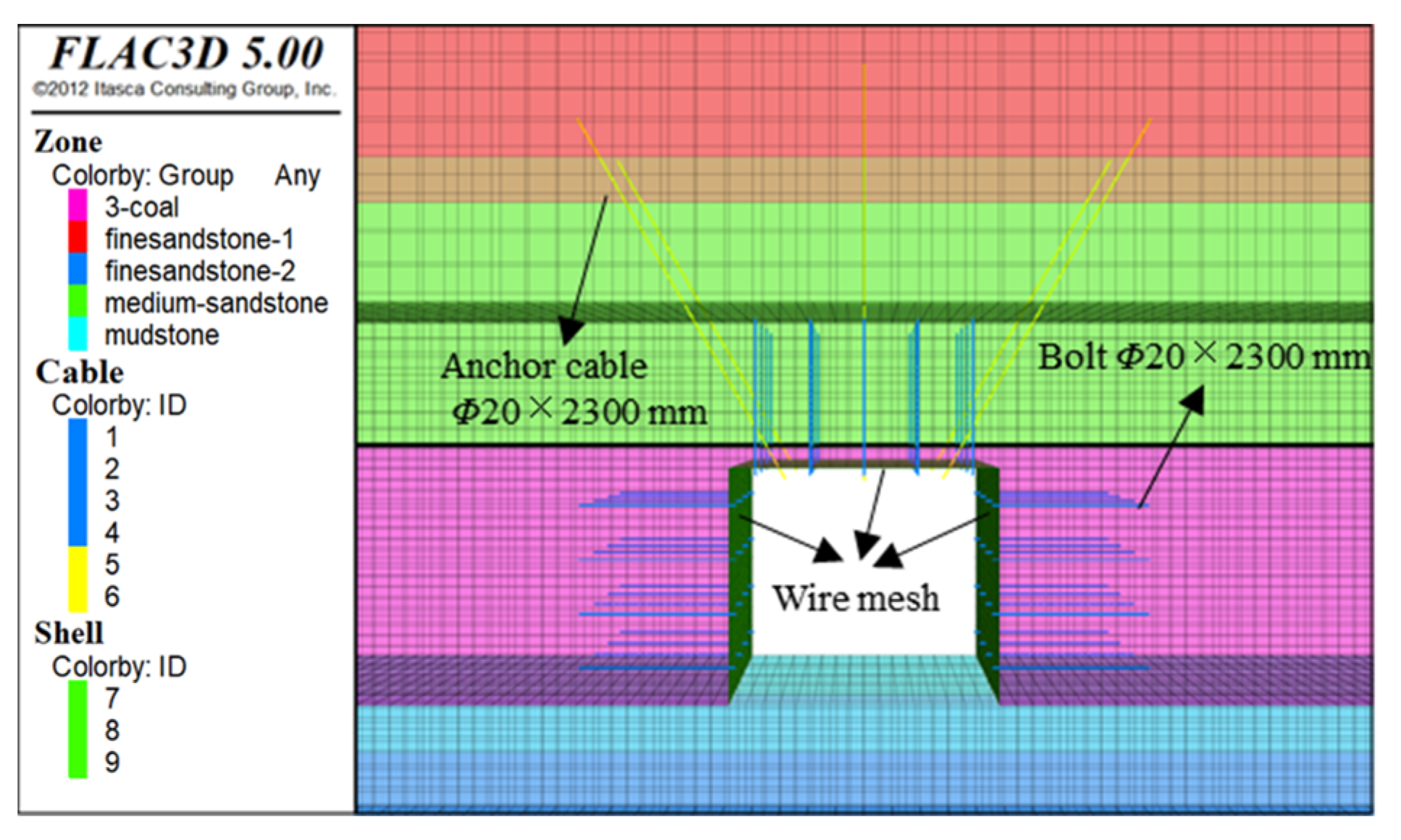
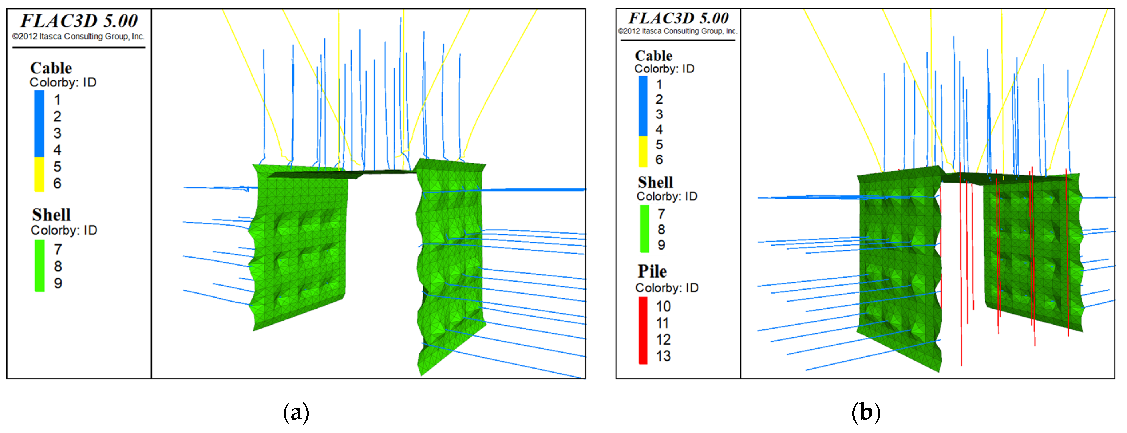
Bolt mesh cable support model of mining roadway
The bolt-mesh-cable support model of the mining roadway is shown in Figure 8. Among them, Cable units’ ID 1, ID 2, ID 3, and ID 4 are the corresponding four-row models with a row spacing of 800 × 800 mm, which are Φ20 × 2300 mm roof bolts and side bolts; the Cable units ID 5 and ID 6 are two rows of Φ17.8 × 6300 mm top anchor cables with the corresponding spacing of 1300 × 2400 mm. Shell units ID 7, ID 8, and ID 9 are wire mesh laid on the roof and on the left and right sides of the corresponding roadway.
(5)
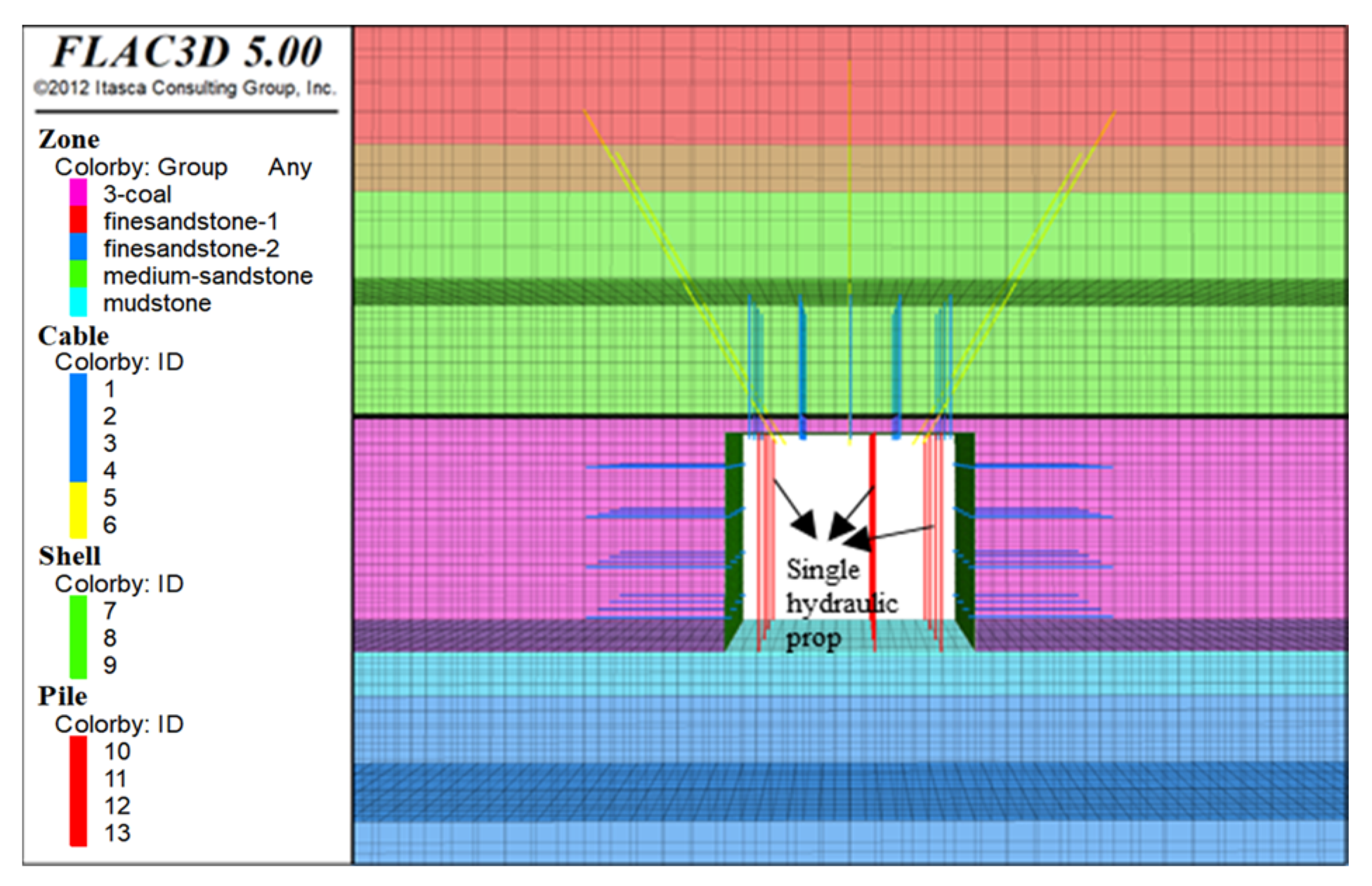
The single hydraulic prop support model
The advanced support of the single hydraulic prop in the mining roadway is shown in Figure 9; the Pile unit IDs 10, 11, 12, and 13 are the single hydraulic props with the corresponding spacing of 1000 mm and the four rows of DW38-250/110XL (see Figure 2). The stable working resistance of the single hydraulic prop is 250 kN, which is closely supported by the top and bottom plates and does not produce displacement in the X and Y directions.
(6)
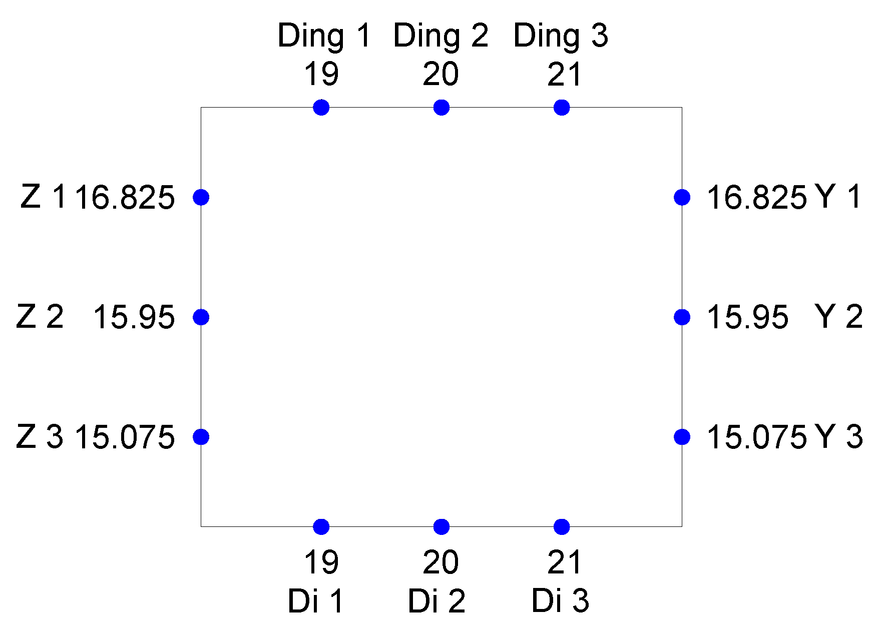
Measuring point arrangement
After establishing the support model of the mining roadway, in order to better monitor the deformation of the mining roadway, the measuring points of the surrounding rock around the mining roadway are arranged, and the distribution is shown in Figure 10. At each monitoring point, the survey line is laid vertically into the coal body.

3.3. Simulation Results and Analysis

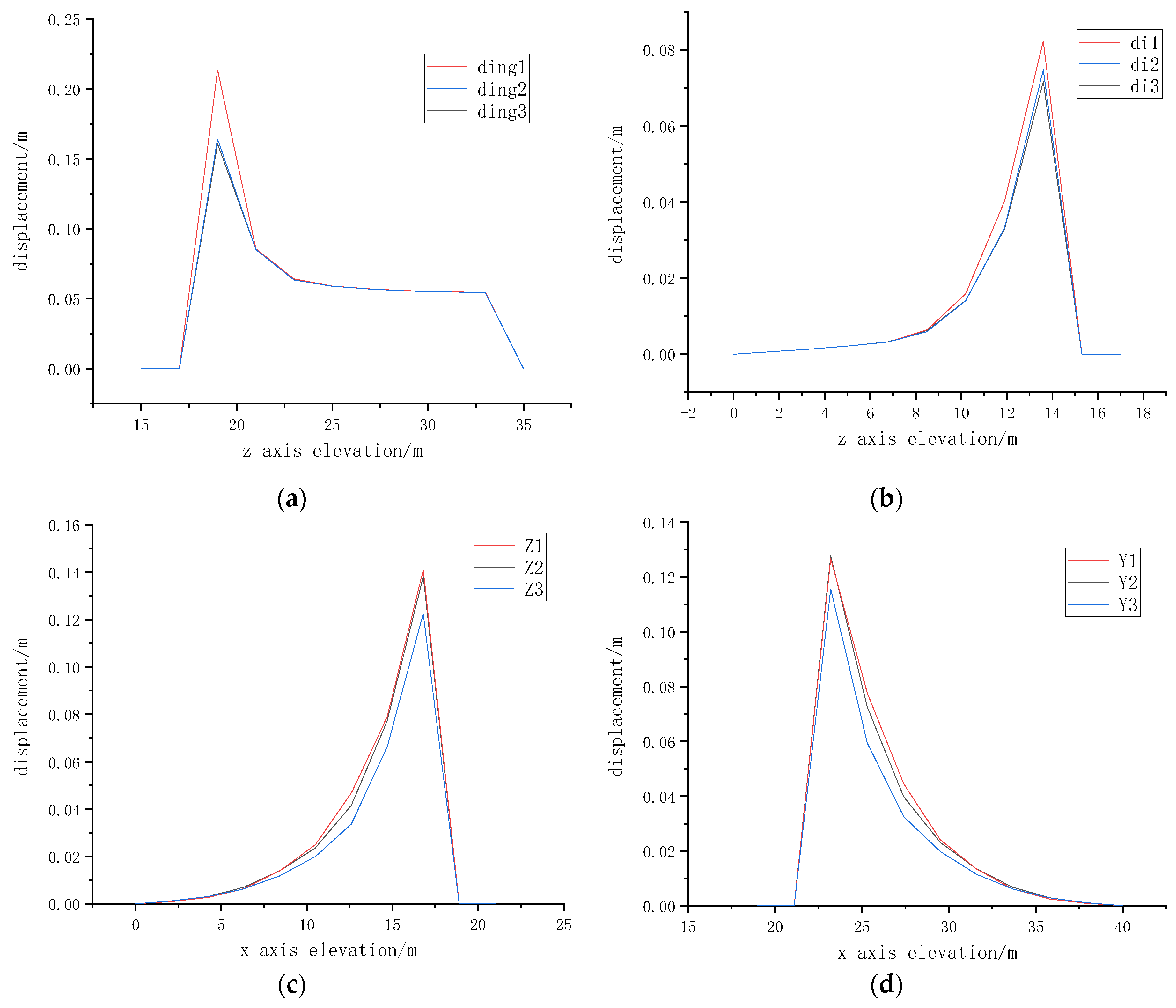
3.3.1. Data Analysis of Roadway Surface Monitoring Points

The monitoring points are arranged on the surface of the roadway to monitor the deformation of the roadway. By processing the historical monitoring information derived from the measuring points, we can obtain the deformation of different positions around the roadway in the whole process of initial support → roadway deformation → roadway stability. The axis elevation-displacement curve obtained by processing is shown in Figure 11.
From the curve diagram combined with the monitoring data, the displacements of the roadway roof measuring points Ding 1, Ding 2, and Ding 3 all reached the maximum, and the roof subsidence of the Ding 1 measuring point was the largest, indicating that the roof had the largest subsidence at the upper left corner of the roof and that the deformation and failure were relatively serious. The floor heave of roadway floor monitoring points Di 1, Di 2, and Di 3 reaches the inflection point at z = 19, and then the deformation convergence rate tends to be gentle, but the overall floor heave is still increasing.

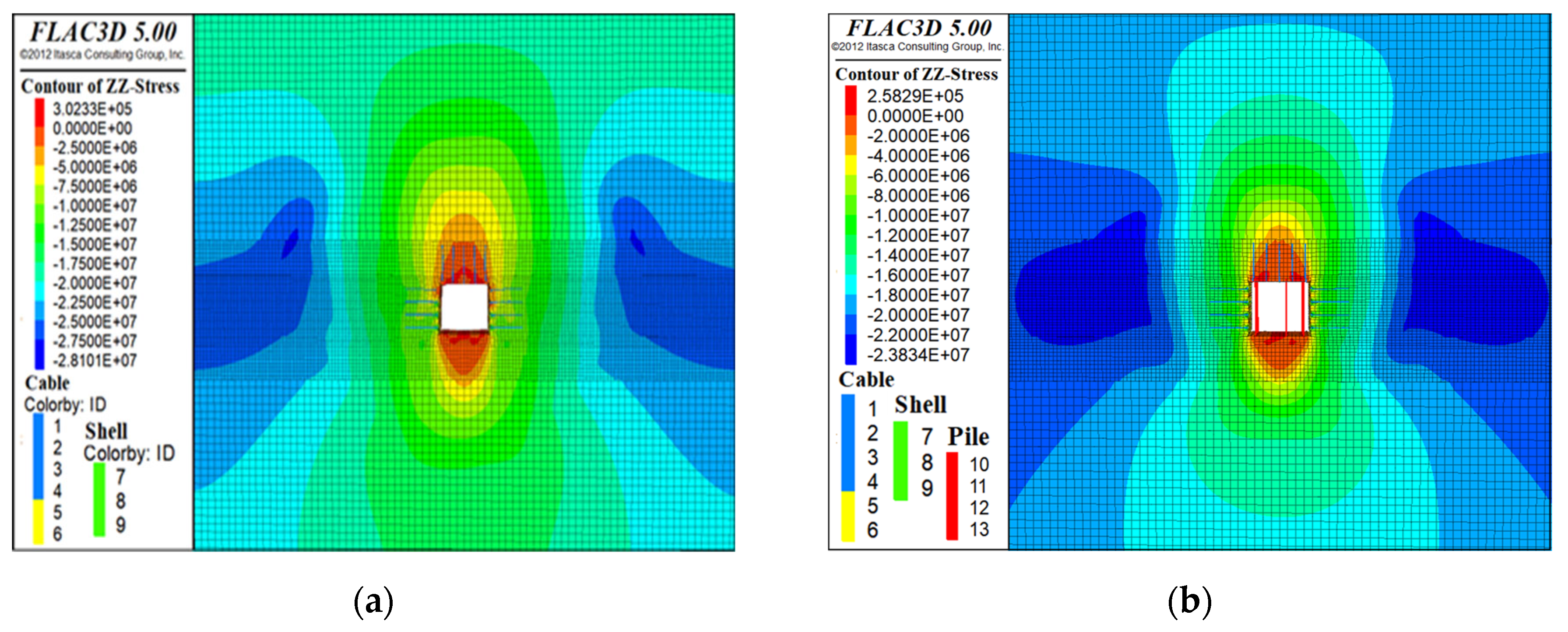
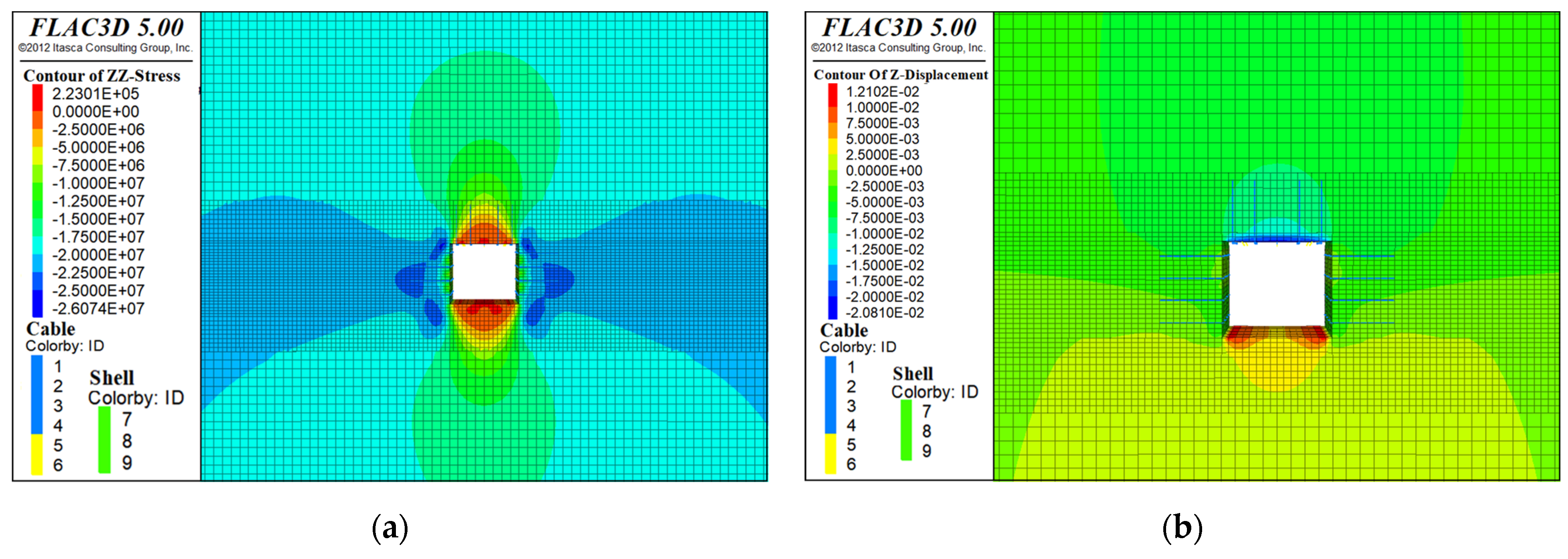
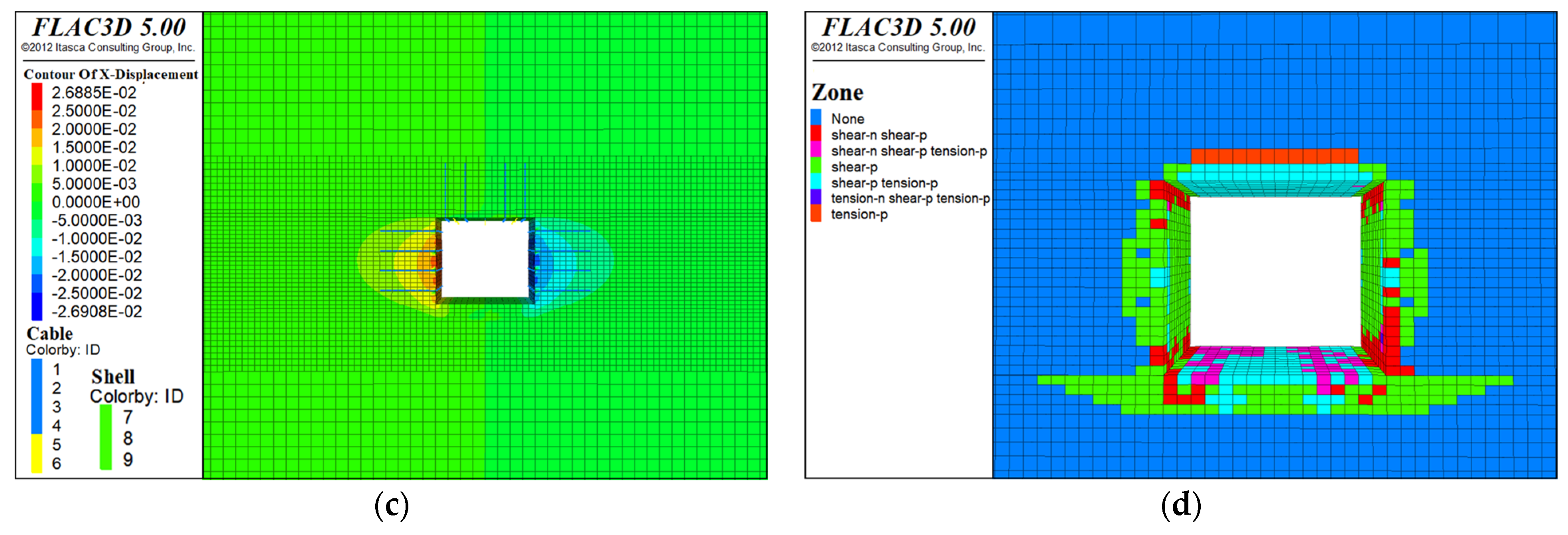
3.3.2. Analysis of the Cloud Map

The vertical stress, vertical displacement, horizontal displacement, and plastic zone distribution of roadway surrounding rock under the two schemes are shown in Figure 12. Structural element analysis of schemes 1 and 2 is shown in Figure 13.
Stress analysis of the surrounding rock in the roadway. When the first scheme is adopted, there is a tensile stress zone in the range of about 6124 mm in the middle of the floor span and about 4000 mm in the left and right, and the maximum tensile stress is about 0.3 MPa, which is smaller. The stress concentration is obvious near the waist line of the two sides of the roadway and the four corners of the roadway. The maximum compressive stress value is about 28.1 MPa at about 10,000 mm deep coal walls on both sides of the roadway. After the single hydraulic support is used, the maximum tensile stress is reduced to 0.26 MPa, and the maximum compressive stress value is reduced to 23.8 MPa. However, the maximum compressive stress value appears in the range of 11,000 mm deep in the coal wall, indicating that the stress concentration is transferred to the deeper part of the coal wall, which is beneficial to the stability of the coal wall.
Analysis of the deformation of the roof and floor of the roadway and the two sides of the roadway. Under the condition of the first support, the maximum subsidence of the roof is 397 mm, the maximum floor heave is 141 mm, and the roof-to-floor convergence is 538 mm. Under the support condition of scheme two, the maximum subsidence of the roof is 211 mm, the maximum floor heave is 77 mm, and the roof-to-floor convergence is reduced to 288 mm. Although the control effect of the second scheme on the surrounding rock is increased, the deformation control of the surrounding rock still does not meet the requirements. Under the condition of the first support, the deformation of the left side of the roadway is 293 mm, the deformation of the right side is 235 mm, and the total convergence of the two sides is 528 mm. Under the support condition of the second scheme, the deformation of the left side of the roadway is 154 mm, the deformation of the right side of the roadway is 154 mm, and the total convergence of the two sides is 308 mm. Under the advanced support of the single hydraulic prop, the deformation of the roadway is relatively controlled, and the total deformation is reduced by 220 mm.
Analysis of bolt and wire mesh support under different support schemes. From Figure 13, under the condition of bolt-mesh-cable support in scheme one, the bolt and wire mesh at the upper corner of the left side of the mining roadway are separated, and the deformation of the coal side makes the bolt clamped in the surrounding rock of the left side of the coal roadway. Under the condition of single hydraulic prop support in scheme 2, the wire mesh on both sides of the surrounding rock of the mining roadway is fixed on the coal side by the bolt, so multiple mesh protrusions are formed, which are prone to mesh pockets and rib spalling.
Analysis of the plastic zone of the roadway surrounding rock. Under the condition of the first support, the plastic zone of the roadway roof is about 28.1 m in the middle of the roadway roof, 8.1 m high, the plastic zone of the two sides is about 18.9 m, and the plastic zone of the floor is about 7.7 m high. Under the support condition of the second scheme, the plastic zone of the roadway roof is reduced to 20.3 m around the mid-span and 6 m high, and the plastic zone of the roof machine floor is smaller in the upper part of the roof and the lower part of the floor. The plastic zone of the roof and floor is caused by tensile stress.

4. Full-Stress Anchoring Technology of Bolts in the Coal Roadway

4.1. Principle of Full-Stress Anchoring Support Technology

In order to solve the problems of support, slow withdrawal, poor support effect, production efficiency and safety, and capital investment in the advance support of single hydraulic props, a full-stress anchoring support technology for coal roadway roofs is proposed to improve this. According to the previous research of the author, the realization method of the full-stress anchoring support technology of the coal roadway roof is obtained [49] as follows:
(1)
Increase the pre-tightening force of the bolt and select the appropriate bolt length according to the strength of the surrounding rock. Increasing the initial pre-tightening force of the bolt will increase the stress value of the pre-tightening force in the full-length range of the bolt anchorage, so that there is a higher stress distribution in the whole surrounding rock range of the bolt anchorage and the control effect on the surrounding rock of the roadway is enhanced. The selection of bolt length depends on the lithology of the surrounding rock, the development of cracks and joints, and the mechanical strength of the coal and rock mass. For the roadway with more developed fissures and joints, where the main body of the surrounding rock is soft rock and the shallow part of the surrounding rock is broken, it is necessary to increase the length of the bolt to anchor the bolt to the deep part of the surrounding rock to reduce the expansion and deformation of the surrounding rock from the inside to the outside.
(2)
In the process of bolt anchoring, synergistic use of quick-setting and retarding anchoring agents. Drilling the surrounding rock of the roadway and the depth of the hole should be matched with the length of the selected bolt. Generally, the depth of the hole is less than the length of the bolt by 100–150 mm. Cleaning the generated cuttings out of the borehole will avoid the influence of cuttings on the process of anchoring the surrounding rock. Firstly, place the quick-setting anchoring agent in the deepest part of the borehole, and then place the retarding anchoring agent with the lower setting rate in the borehole. The two anchoring agents are in close contact, and then the bolt is inserted and stirred. When the quick-setting anchoring agent is anchored and the retarding anchoring agent has not yet condensed, the pre-tightening force is applied to the bolt to realize the distribution of the pre-tightening force along the full length of the bolt, so that the surrounding rock within the full length of the bolt is subjected to effective compressive stress. The diameter of the quick-setting anchoring agent and the retarding anchoring agent should be consistent, and the quick-setting anchoring agent and the retarding anchoring agent with different diameters should not be used. In this way, after the two anchoring agents are stirred, the distribution of the anchoring agent is more consistent, which avoids the problem of uneven distribution of the anchoring agent and enhances the control effect of the bolt on the deformation of the surrounding rock and the separation layer.
(3)
Increase the total anchorage length of the bolt anchorage section and keep the total anchorage length to meet the requirements for lengthening the anchorage. The anchorage section of the full-stress anchorage of the bolt includes two parts: the quick-setting anchorage section and the retarding anchorage section, and the total anchorage length is the sum of the two. The total anchorage length is increased by increasing the amount of anchoring agent, and the amount of retarding anchoring agent should not be less than the amount of quick-setting anchoring agent. Using the different characteristics of the condensation rates of the two anchoring agents, the pre-tightening force is applied to the bolt within the setting time difference. While increasing the distribution range of anchoring stress, it also ensures the high-stress anchoring state of the bolt and improves the overall control strength of the bolt to the surrounding rock.

4.2. Full-Stress Bolt Anchoring Support Technology Scheme and Supporting Effect Analysis

According to the principle of full-stress anchoring technology, the advanced support optimization scheme of the mining roadway on the 1304 working face is designed as follows:
(1)
Increase the length of the bolt; use a Φ20 × 2400 mm bolt, spacing 800 × 800 mm; lengthen the length of the anchor cable, using Φ17.8 × 7300 mm, spacing 1300 mm, row spacing 2400 mm, interval arrangement. The selection of anchor cable support length is related to the distribution of the plastic zone of the surrounding rock and the method of full-stress anchorage support. The anchor cable needs to be anchored into the hard and stable fine sandstone because the distribution range of the plastic zone of the fine sandstone surrounding rock is smaller than that of the medium sandstone, and the damage degree of the surrounding rock is low, which is beneficial to the suspension of the anchor cable. In addition, one CK2350 anchoring agent and two K2370 anchoring agents are used in the full-stress anchoring of the anchor cable. The theoretical anchoring length is 1900 mm, and the anchoring section should be all in fine sandstone, which is conducive to giving full play to the overall anchoring performance of the anchoring section and improving the full-stress anchoring support effect. Therefore, under the above conditions, the shortest length of anchor cable is, in theory, 6750 mm. In this case, the length of the anchor cable is increased, and the Φ17.8 × 7300 mm anchor cable is used. In addition to satisfying the full-stress anchorage condition, the anchorage section can be kept away from the interbedded positions of fine and medium sandstone, thus improving the shear resistance of the anchor cable.
(2)
Bolt pre-tightening force increased from 80 kN to 120 kN; anchor cable pre-tightening force increased from 92 kN to 130 kN.
(3)
Use quick-setting and retarding anchoring agents. The bolt is anchored by one CK2350 anchoring agent and one K2370 anchoring agent, and the anchor cable is anchored by one CK2350 and two K2370 anchoring agents.
Based on the full-stress anchoring support scheme, two methods of single hydraulic prop support and full-stress anchoring bolt support are compared. In order to more intuitively reflect the support effect of the full-stress anchoring support technology on the mining roadway of the working panel, this paper analyzes the advance support effect from four aspects: vertical stress, vertical displacement, horizontal displacement, and plastic zone distribution, as shown in Figure 14.
In terms of maximum concentrated stress. Comparing Figure 14a with Figure 12b, the maximum concentrated stress under the full-stress anchorage advance support is about 26.1 MPa, and the maximum concentrated stress is mainly distributed in two positions. The first position is within the range of 1200–3000 mm from the roadway side, with a horizontal span of 1800 mm and a vertical span of 2200 mm. The second position is within the range of 500–1500 mm from the roof corner and the floor corner of the roadway, with a horizontal span of 1000 mm and a vertical span of 1500 mm. The maximum concentrated stress area of the surrounding rock around the roadway is about 13.92 m2. The maximum concentrated stress under the advanced support of the single hydraulic prop is about 23.8 MPa. The maximum concentrated stress is mainly distributed in the range of 6500–13,500 mm from the roadway side, the horizontal span is 7000 mm, the vertical span is 8100 mm, and the maximum concentrated stress area of the surrounding rock around the roadway is about 113.4 m2. Under the full-stress anchoring advance support, although the maximum concentrated stress increases by 2.3 MPa compared with the 23.8 MPa of the single hydraulic prop advance support, the increase is not large, only 9.7%. In contrast, the maximum concentrated stress range is reduced by 99.48 m2 compared with the 113.4 m2 of the single hydraulic prop advance support, which is reduced by 7.1 times, and the maximum concentrated stress range is greatly reduced.
Analysis of roadway surrounding rock deformation. Comparing Figure 14b with Figure 12d, under the full-stress anchoring advance support, the maximum subsidence of the roadway roof is 21 mm, the maximum floor heave is 12 mm, and the maximum convergence of the roof and floor is 33 mm. Under the single hydraulic prop advance support, the maximum subsidence of the roadway roof is 211 mm, the maximum floor heave is 77 mm, and the maximum convergence of the roof and floor is 288 mm. The full-stress anchoring advance support reduces the maximum convergence of the roadway roof and floor by 255 mm, and the stability of the surrounding rock of the roadway roof and floor is significantly enhanced. Compared with Figure 14c and Figure 12f, the maximum displacement of the left and right sides of the roadway is reduced from 154 mm to 26 mm, the maximum convergence of the two sides is reduced from 308 mm to 52 mm, and the deformation of the surrounding rock of the roadway is significantly reduced.
Analysis of plastic zone distribution. Under the full-stress anchoring advance support, the plastic zone of the roadway roof is distributed in the range of 800 mm above the roof, the plastic zone span on both sides of the roadway is about 600 mm, and the plastic zone of the floor is distributed in the range of 1000 mm below the floor. Under the advanced support of the single hydraulic prop, the plastic zone of the roadway roof is within 6000 mm above the middle of the roof, the plastic zone span on both sides of the left and right sides is about 1800 mm, and the plastic zone of the floor is within 4700 mm below the floor. Compared with single hydraulic prop advanced support, full-stress anchor anchoring support reduces the height of the plastic zone of the roof by 5200 mm, the span of the plastic zone of the left and right sides by 1200 mm, and the depth of the plastic zone of the bottom plate by 3700 mm. The full-stress anchoring support greatly reduces the plastic zone of the roadway surrounding rock and greatly improves the integrity of the surrounding rock.
Based on the analysis of vertical stress, vertical displacement, horizontal displacement, and plastic zone distribution, compared with the single hydraulic prop advanced support, the full-stress anchoring advance support of a bolt has a better control effect on the maximum concentrated stress range of the mining roadway, the deformation of the roadway roof, floor, and two sides, and the plastic zone of the roadway surrounding rock, which can meet the requirements of safe production. Through the above comparative analysis of the supporting effects of the two advanced support methods, it is clear that the effect of the full-stress anchoring support on the surrounding rock control of the mining roadway in the working panel is better than the single hydraulic prop advanced support. Full-stress anchoring technology can be used as a new advanced support technology to replace the single hydraulic prop to achieve effective control of the mining roadway.

4.3. Roadway Deformation Monitoring

After using the optimization scheme of bolt full-stress anchoring support technology in the return airway of the 1304 working face, the cross-section method is used to monitor the deformation of the roof and floor and the deformation of two sides of the mining roadway. The Nohawk L-40 two-way laser rangefinder was used to observe the deformation of roadway surrounding rock. Based on the principle of the cross-observation method and combined with Figure 10, the distances between Ding 1 and Di 1, Ding 2 and Di 2, and Ding 3 and Di 3 were measured. The deformation of the three groups was recorded, and the average value was taken as the convergence of the roof and floor of the roadway. Similarly, the distances between Z 1 and Y 1, Z 2 and Y 2, and Z 3 and Y 3 on the left and right sides of the roadway were measured, the deformation of the three groups was recorded, and the mean value was taken as the convergence of the left and right sides of the roadway. The station is set 100 m ahead of the working panel, and every 5 m of the working panel is observed and recorded. The deformation of the roadway under the influence of one mine is shown in Figure 15.
According to Figure 15, the maximum roof subsidence of the return air roadway in the Yineng Coal Mine 1304 working face is 25 mm, the maximum floor heave is 17 mm, and the maximum roof-to-floor convergence is 42 mm. The maximum deformation of the mining side of the return air roadway is 41 mm, the maximum deformation of the non-mining side is 28 mm, and the total maximum convergence of the two sides is 69 mm. According to the deformation rate of the roof and floor of the roadway and the deformation rate of the roadway, the deformation rate of the roof and floor is faster in the range of 0–50 m for the advanced roadway. This stage is the process of roof rotation and fracture, often accompanied by the phenomenon of mine pressure such as roof surrounding rock fragmentation and cracks. The overall deformation rate of the surrounding rock of the 50–100 m mining roadway decreases, the deformation tends to be stable, and the roadway is in the original rock stress zone. During the mining process, the total deformation rate of the two sides of the roadway is relatively stable, and the deformation of the roadway is not severe.
The overall deformation of the return airway of the 1304 working face meets the engineering application standard, and the deformation is within the allowable deformation range. The stability of the surrounding rock of the roadway is controlled. The field application effect is shown in Figure 16. In summary, the bolt full-stress anchoring technology has a good effect on the process of roadway support in the advanced section of coal roadway affected by mining, and the industrial application is successful.

5. Conclusions

(1)
Through FLAC3D finite difference software, two kinds of transportation roadway support models—single hydraulic prop advance support and simple bolt-mesh-cable support—are established. The two schemes are compared in four aspects: vertical stress, vertical displacement, horizontal displacement, and plastic zone distribution. Compared with the simple bolt-mesh-cable support, the tensile stress value of the roof and floor of the roadway is reduced from 0.3 MPa to 0.26 MPa, the roof-to-floor convergence is reduced from 538 mm to 288 mm, and the convergence of the two sides is reduced from 528 mm to 308 mm. The plastic zone above the roof of the roadway is reduced from 28.1 m long and 8.1 m high to 20.3 m long and 6 m high. The plastic zone on both sides of the roadway is reduced from 18.9 m to 10 m, and the height is reduced from 8 m to 5.9 m. The stress concentration and deformation of the roadway are reduced, and the distribution range of the plastic zone is smaller. This shows that the single hydraulic prop advanced support changes the stress and deformation state of the surrounding rock of the mining roadway to a certain extent and makes the roadway more stable.
(2)
The numerical simulation experiment is used to simulate and analyze the effect of full-stress anchoring advance support of bolts and single hydraulic prop advance support. From the numerical simulation analysis experiment, we determined that, compared with the single hydraulic prop advance support, the effect of full-stress anchoring advance support of bolts is as follows: The area of the maximum concentrated stress area is reduced by 7.1 times, the maximum convergence of the roadway roof and floor is reduced from 288 mm to 33 mm, and the maximum convergence of the left and right sides is reduced from 308 mm to 25 mm, and the height of the plastic zone of the roof is reduced from 6000 mm to 800 mm, the span of the plastic zone on both sides is reduced from 1800 mm to 600 mm, and the depth of the plastic zone of the floor is reduced from 4700 mm to 1000 mm. The effect of full-stress anchoring support technology is better than that of single hydraulic prop advance support, which greatly improves the control effect of the roadway surrounding rock.
(3)
The realization method of full-stress anchoring support of bolts is proposed: Increase the anchorage length of the bolt, increase the pre-tightening force of the bolt, and use the quick-setting anchoring agent and the retarding anchoring agent. The advanced support scheme for full-stress anchoring is formulated as follows: The length of the bolt is 2400 mm, the pre-tightening force is 120 kN, the spacing and row spacing are both 800 mm, and the anchoring agents are CK2350 and K2370. The length of anchor cable is 7300 mm, the spacing of anchor cable is 1500 mm, the row spacing is 2000 mm, the pre-tightening force is 150 kN, and one CK2350 and two K2370 anchoring agents are used for anchoring. In the industrial test, compared with the single hydraulic prop advance support, the roof-to-floor convergence of the roadway is reduced from 500 mm to 42 mm, and the control effect on the deformation of the roof and floor is increased by 1009%; the convergence of the two sides of the roadway is reduced from 300 mm to 69 mm, and the control effect on the deformation of the left and right sides is increased by 335%. The industrial test results show that the supporting effect of bolt full-stress anchoring advance support technology on the roadway surrounding rock is better than that of single hydraulic prop advance support technology.
(4)
The supporting effect of full-stress anchoring support technology on the surrounding rock of the mining roadway in the advanced section of the working panel is better than that of single hydraulic prop support technology. At the same time, the full-stress anchoring support has more advantages in economic benefits and production safety than the single hydraulic prop support. Therefore, it is reasonable to use the full-stress anchoring support technology to replace the original single hydraulic prop support technology, which can be used as the support technology of the mining roadway in the advance section of the working panel in coal mining. In future research, the failure factors and bearing capacity of full-stress anchoring support will be studied, and the whole process of full-stress anchoring of bolts will be monitored, from initial stress through anchorage service and anchorage failure. The influence of four different factors, such as anchorage length, bond strength, surrounding rock strength, and bolt strength, on the distribution effect of full-stress anchoring stress of the bolts is obtained so as to further improve the effect of full-stress anchoring support.

Author Contributions

Conceptualization, X.G. and X.Z.; methodology, X.G.; software, X.G., G.L. and P.L.; validation, X.G., C.L. and J.W.; formal analysis, X.G.; investigation, B.L., W.X. (Wenjie Xu) and H.X.; resources, N.M.S.; data curation, X.G., Y.W. and W.X. (Wei Xin); writing—original draft preparation, X.G.; writing—review and editing, X.G., P.L. and X.Z.; project administration, X.G. All authors have read and agreed to the published version of the manuscript.

Funding

This research was funded by the National Natural Science Foundation of China (No. 51574226), the Postgraduate Research and Practice Innovation Program of Jiangsu Province (2023, No. KYCX22_2623), the Graduate Innovation Program of the China University of Mining and Technology (2023, No. 2022WLJCRCZL007), and the Fundamental Research Funds for the Central Universities. Thank you for the above funds and units.

Institutional Review Board Statement

Not applicable.

Informed Consent Statement

Not applicable.

Data Availability Statement

Data are contained within the article.

Conflicts of Interest

The authors declare no conflict of interest.

References

  1. Xu, P.F. Characteristics and occurrence regularity of coal mine accidents in China from 2020 to 2021. Coal Eng. 2022, 54, 129–133. [Google Scholar]
  2. Zhang, P.S.; Li, F.X.; Zhu, H.C.; Niu, H.; Li, X.H. Statistical analysis and prevention countermeasures of coal mine accidents from 2008 to 2020. Min. Saf. Environ. Prot. 2022, 49, 128–134. [Google Scholar]
  3. Meng, Y.; Xie, D.H.; Su, B.; Gu, A.X. Statistics and analysis of coal mine production safety accidents in China from 2010 to 2019. Miner. Eng. Res. 2020, 35, 27–33. [Google Scholar]
  4. National Mine Safety Administration, National Mine Safety Production Accidents in 2022. Available online: https://www.chinamine-safety.gov.cn/zfxxgk/fdzdgknr/sgcc/sgtb/202302/t20230215_442433.shtml (accessed on 15 February 2023).
  5. Ren, H.; Zhu, Y.J.; Peng, X.Y.; Li, Y. Numerical simulation of reasonable position layout of lower coal mining roadway under short-distance thin coal seam. Min. Res. Dev. 2023, 43, 8–13. [Google Scholar]
  6. Yuan, S.; Liu, J.Y. Study on reasonable pillar width of mining roadway under district pillar in overlying section. Coal Eng. 2022, 54, 1–5. [Google Scholar]
  7. Miao, Y.P.; Cheng, L.X.; Zheng, X.H.; Chen, X.S.; Wang, Z.L.; Xu, B.J. Study on dynamic response characteristics of mining stress in shallow deep mining roadway. J. Min. Strata Control Eng. 2022, 4, 60–68. [Google Scholar]
  8. He, F.; Li, L.; Lv, K.; Qin, B.; Xu, X.; Ma, Q.; Chen, Y. Study on evolution of front abutment pressure at working face in repeated mining of close-distance coal seams. Sustainability 2022, 14, 12399. [Google Scholar] [CrossRef]
  9. Qin, H.Y.; Cheng, Z.H.; Ouyang, Z.H.; Zhao, X.D.; Feng, J.C. Relationship between advancing abutment pressure and deformation of surrounding rock in a roadway: A case study in Helin coal mine in China. Environ. Earth Sci. 2021, 80, 763. [Google Scholar] [CrossRef]
  10. Fu, Q.; Yang, K.; He, X.; Liu, Q.; Wei, Z.; Wang, Y. Destabilization mechanism and stability control of the surrounding rock in stope mining roadways below remaining coal pillars: A case study in Buertai coal mine. Processes 2022, 10, 2192. [Google Scholar] [CrossRef]
  11. Tan, Y.L.; Liu, X.S.; Ning, J.G.; Tian, C.L. Front abutment pressure concentration forecast by monitoring cable-forces in the roof. Int. J. Rock Mech. Min. Sci. 2015, 77, 202–207. [Google Scholar] [CrossRef]
  12. Jin, Z.; Xu, Y.; Peng, T.; Gao, L. Roof control technology of mining roadway under the influence of advanced supporting pressure. Adv. Civ. Eng. 2021, 2021, 2049755. [Google Scholar] [CrossRef]
  13. Liu, H.; Jiang, Z.H.; Chen, W.S.; Chen, F.; Ma, F.L.; Li, D.H.; Liu, Z.Y.; Gao, H.K. A simulation experimental study on the advance support mechanism of a roadway used with the longwall coal mining method. Energies 2022, 15, 1366. [Google Scholar] [CrossRef]
  14. Xue, G.; Cheng, J.; Guan, J.; Chai, J.; Zhang, G.; Hao, X.; Wu, M. The method for determining working resistance of advance support bracket in deep fully mechanized roadway based on Flac3D. Adv. Mech. Eng. 2018, 10, 1–10. [Google Scholar] [CrossRef]
  15. Su, W.; Zheng, B.; Jiang, P. Study on anchor cable instead of single hydraulic prop support in advance support of deep roadway. Adv. Civ. Eng. 2021, 2021, 6644832. [Google Scholar] [CrossRef]
  16. Jiao, X.J.; Du, F.; Wang, L.J.; Wang, W.Q. Cooperative control technology of advanced active support in fully mechanized caving face of gently inclined thick coal seam. Coal Technol. 2022, 41, 22–27. [Google Scholar]
  17. Chen, J.G.; Tang, J.Q.; Zhuo, J. Research and application of horizontal end and advanced hydraulic support in fully mechanized mining face. Coal Technol. 2022, 41, 212–215. [Google Scholar]
  18. Du, W.J. Application of over-advance support in the over-advance support of the return roadway of the isolated working face. Mech. Manag. Dev. 2021, 36, 169–170. [Google Scholar]
  19. Chen, Y.L.; Zhang, Z.M.; Wang, H.B. Research on non equal strength support technology and automatic control device of hydraulic support in advance support. Shandong Coal Sci. Technol. 2021, 39, 123–125. [Google Scholar]
  20. Liu, J. Development and application analysis of advanced support hydraulic support. Coal Mine Mach. 2019, 40, 132–133. [Google Scholar]
  21. Wang, Q. Application of roadway advanced hydraulic support in fully mechanized coal mining. Coal Mine Mach. 2017, 22, 30–31. [Google Scholar]
  22. Liu, X.H. Advance support technology of gob side entry without support in coal mining face. Coal Eng. 2017, 49, 38–40. [Google Scholar]
  23. Kang, H.P. Development and prospects of support and reinforcement materials for coal mine roadways. Coal Sci. Technol. 2021, 49, 1–11. [Google Scholar]
  24. Chen, F.; Wang, X.-B.; Wang, J.-G. Research on the propagation law of stress wave in rock mass supported by bolt under dynamic load. Geofluids 2022, 2022, 6022757. [Google Scholar] [CrossRef]
  25. Cao, F.; Fang, T. Application and analysis of bolt support in mine driving roadway. Math. Probl. Eng. 2022, 2022, 2521555. [Google Scholar] [CrossRef]
  26. Zakharov, V.N.; Trofimov, V.A.; Filippov, Y.A. Numerical modeling of rock bolt support in case of rheological behavior of rock mass in deformation. J. Min. Sci. 2021, 57, 883–893. [Google Scholar] [CrossRef]
  27. Chen, J.; Liu, P.; Zhao, H.; Zhang, C.; Zhang, J. Analytical studying the axial performance of fully encapsulated rock bolts. Eng. Fail. Anal. 2021, 128, 105580. [Google Scholar] [CrossRef]
  28. Yuan, Y.; Tu, S.H.; Zhang, X.G.; Li, B. Dynamic effect and control of key strata break of immediate roof in fully mechanized mining with large mining height. Shock Vib. 2015, 2015, 657818. [Google Scholar]
  29. Wang, S.; Xiang, Z.; Deng, J.; Yang, H.; Yang, X.; Jin, S. Analysis of cooperative control effect of pressure relief and long bolt support for deep roadway under strong mining disturbance of adjacent working face. Geotech. Geol. Eng. 2021, 39, 2259–2268. [Google Scholar] [CrossRef]
  30. Skrzypkowski, K. Case studies of rock bolt support loads and rock mass monitoring for the room and pillar method in the legnica-glogow copper district in Poland. Energies 2020, 13, 2998. [Google Scholar] [CrossRef]
  31. Skrzypkowski, K.; Korzeniowski, W.; Zagórski, K.; Zagórska, A. Modified rock bolt support for mining method with controlled roof bending. Energies 2020, 13, 1868. [Google Scholar] [CrossRef] [Green Version]
  32. Wang, Y.; Yuan, C.; Shi, X.; Chang, Q.; Zhang, B. Study on dynamic failure characteristics of coal and rock in stope induced by dynamic load of steep horizontal sublevel mining. Processes 2022, 10, 1684. [Google Scholar] [CrossRef]
  33. Kang, H.; Yang, J.; Gao, F.; Li, J. Experimental study on the mechanical behavior of rock bolts subjected to complex static and dynamic loads. Rock Mech. Rock Eng. 2020, 53, 4993–5004. [Google Scholar] [CrossRef]
  34. Kang, H. Support technologies for deep and complex roadways in underground coal mines: A review. Int. J. Coal Sci. Technol. 2014, 1, 261–277. [Google Scholar] [CrossRef] [Green Version]
  35. Hou, C.; Wang, X.; Bai, J.; Meng, N.; Wu, W. Basic theory and technology study of stability control for surrounding rock in deep roadway. J. China Univ. Min. Technol. 2021, 50, 1–12. [Google Scholar]
  36. Zhang, N.; Han, C.L.; Xie, Z.Z. Theory of continuous beam control and high efficiency supporting technology in coal roadway. J. Min. Strata Control Eng. 2019, 1, 48–55. [Google Scholar]
  37. Krykovskyi, O.; Krykovska, V.; Skipochka, S. Interaction of rock-bolt supports while weak rock reinforcing by means of injection rock bolts. Min. Miner. Depos. 2021, 15, 8–14. [Google Scholar] [CrossRef]
  38. Rehman, Z.U.; Hussain, S.; Tahir, M.; Sherin, S.; Mohammad, N.; Dasti, N.; Raza, S.; Salman, M. Numerical modelling for geotechnical assessment of rock mass behaviour and performance of support system for diversion tunnels using optimized Hoek-Brown parameters. Min. Miner. Depos. 2022, 16, 1–8. [Google Scholar] [CrossRef]
  39. Ghazdali, O.; Moustadraf, J.; Tagma, T.; Alabjah, B.; Amraoui, F. Study and evaluation of the stability of underground mining method used in shallow-dip vein deposits hosted in poor quality rock. Min. Miner. Depos. 2021, 15, 31–38. [Google Scholar] [CrossRef]
  40. Yin, Y.; Zhao, T.; Tan, Y.; Zhang, Z. Research of stress distribution evolution law and influencing factors. J. Min. Saf. Eng. 2013, 30, 712–716. [Google Scholar]
  41. Zheng, X.; Zhang, N.; Xue, F. Study on stress distribution law in anchoring section of prestressed bolt. J. Min. Saf. Eng. 2012, 29, 365–370. [Google Scholar]
  42. Zheng, X.; Zhang, L.; Zhang, N.; Liu, N. Pre-stressed anchorage function and evolution in the roof of rectangular roadway in deep mine. J. China Univ. Min. Technol. 2013, 42, 929–934. [Google Scholar]
  43. Zheng, X.; Liu, N.; Zhang, N.; Hua, J.; Feng, X. Floor heave mechanism and control technology of flexural and folded deep mine roadway. J. China Coal Soc. 2014, 39, 417–423. [Google Scholar]
  44. Wang, H.; Wang, Q.; Wang, F.; Li, S.; Wang, D.; Ren, Y.; Guo, N.; Zhang, S. Mechanical effect analysis of bolts in roadway under different anchoring lengths and its application. J. China Coal Soc. 2015, 40, 509–515. [Google Scholar]
  45. Zhao, T.; Xing, M.; Guo, W.; Wang, C.; Wang, B. Anchoring effect and energy-absorbing support mechanism of large deformation bolt. J. Cent. South Univ. 2021, 28, 572–581. [Google Scholar] [CrossRef]
  46. Li, H.Z.; He, X.; Long, L.Q.; Fan, D.P. Experimental on the influence of different constraint conditions on the bearing characteristics of rock bolt. J. Min. Strata Control Eng. 2022, 4, 28–37. [Google Scholar]
  47. Li, H.Z.; Li, X.; Chong, Z.; Long, J. Experimental research on slippage mode and analysis on mechanical properties of coal rock anchorage system. J. Min. Saf. Eng. 2017, 34, 1088–1093. [Google Scholar]
  48. Li, H.Z.; Li, X. Determination of rational anchorage length of bolt based on slip-debonding failure mode of interface. Rock Soil Mech. 2017, 38, 3106–3112. [Google Scholar]
  49. Guo, X.; Zheng, X.; Li, P.; Lian, R.; Liu, C.; Shahani, N.M.; Wang, C.; Li, B.; Xu, W.; Lai, G. Full-stress anchoring technology and application of bolts in the coal roadway. Energies 2021, 14, 7475. [Google Scholar] [CrossRef]
Figure 1. The 1304 working face advanced section mining roadway coal (rock) histogram.
Processes 11 01052 g001
Figure 2. The 1304 working face return air roadway single hydraulic prop advance support diagram. (a) The 1304 working face return airway roadway support section diagram; (b) The 1304 working face return airway roof support top view.
Processes 11 01052 g002
Figure 3. The 1304 working face return air roadway with single hydraulic prop advance support in real life.
Processes 11 01052 g003
Figure 4. Deformation of the 1304 return airway. (a) Roof subsidence of the return airway; (b) Roof surrounding rock surface loose collapse; (c) Bolt tray is out of roof support failure; (d) Coal rib spalling and bending of the single hydraulic prop.
Processes 11 01052 g004
Figure 5. Instruments for measuring rock mechanical parameters.
Processes 11 01052 g005
Figure 6. Test of the physical and mechanical parameters of the surrounding rock. (a) Uniaxial compressive strength test; (b) Uniaxial tensile strength test; (c) Uniaxial shear strength test.
Processes 11 01052 g006
Figure 7. Return air roadway engineering geological model. (a) Initial geologic model; (b) Excavation of the return airway.
Processes 11 01052 g007
Figure 8. Transport roadway public support part.
Processes 11 01052 g008
Figure 9. A mining roadway with the single hydraulic prop advanced support.
Processes 11 01052 g009
Figure 10. Layout of roadway surface monitoring points.
Processes 11 01052 g010
Figure 11. Roadway monitoring point axis elevation-displacement curve. (a) Roof monitoring point z axis elevation-displacement curve; (b) Floor monitoring point z axis elevation-displacement curve; (c) X axis elevation-displacement curve of left side monitoring point; (d) X axis elevation-displacement curve of the right side monitoring point.
Processes 11 01052 g011
Figure 12. Cloud map analysis of schemes 1 and 2. (a) Scheme 1: vertical stress; (b) Scheme 2: vertical stress; (c) Scheme 1: vertical displacement; (d) Scheme 2: vertical displacement; (e) Scheme 1: horizontal displacement; (f) Scheme 2: horizontal displacement; (g) Scheme 1: plastic zone distribution; (h) Scheme 2: plastic zone distribution.
Processes 11 01052 g012aProcesses 11 01052 g012b
Figure 13. Structural elements analysis of schemes 1 and 2. (a) Scheme 1: bolt-mesh-cable support; (b) Scheme 2: bolt-mesh-cable and single hydraulic prop support.
Processes 11 01052 g013
Figure 14. Comparative analysis of supporting effects. (a) Full-stress support vertical stress; (b) Vertical displacement of full-stress support; (c) Horizontal displacement of full-stress support; (d) Plastic zone distribution of full-stress support.
Processes 11 01052 g014aProcesses 11 01052 g014b
Figure 15. Monitoring of deformation and speed of roadway surrounding rock. (a) Deformation of the roof and floor of the roadway; (b) Deformation of the coal sides of the roadway.
Processes 11 01052 g015
Figure 16. Application of full-stress anchoring support in the return airway. (a) Support effect of roof; (b) Side-angle and coal side control effect; (c) Full-stress anchoring of bolt in a full section mining roadway.
Processes 11 01052 g016
Table 1. Incomplete statistics of all kinds of death accidents in coal mines in China from 2014 to 2022.
YearRoofGasMechatronicsWaterTransportationBlastingOthersTotal
NumbersDeath
Toll
NumbersDeath
Toll
NumbersDeath
Toll
NumbersDeath
Toll
NumbersDeath
Toll
NumbersDeath
Toll
NumbersDeath
Toll
NumbersDeath
Toll
20141962924726636371979831031319114131508927
201513417145171313112646268775963350575
201683126362212238152754728143140249538
2017738631132202212183242884367219375
2018619312532019595063222536175275
20195172291131711834161212255170316
2020405552217187252326332879123228
202125537251313328202011212690166
202248891123242272533369113639168245
Total7111037223102618021188278298491536637953620493645
Table 2. Mechanical parameters of coal and rock mass.
Rock
Formation
LithologyThickness
/m
Unit Weight
/(N/m3)
Elastic
Modulus
/GPa
Poisson
Ratio
Internal
Friction
Angle/(°)
Cohesion
/MPa
Compressive Strength
/MPa
Tensile Strength
/MPa
Rooffine sandstone12.926,40010.90.253810.539.071.14
medium sandstone4.325,80010.50.244012.641.021.17
Coal seam 3Coal3.815,4002.550.19303.27.810.63
Floormudstone0.723,30010.130.31261.317.160.82
fine sandstone13.825,40010.90.253810.539.071.14
Table 3. Mechanical parameters of coal and rock mass required for simulation.
Rock
Formation
LithologyThickness
/m
Unit Weight
/(N/m3)
Bulk
Modulus
/GPa
Shear
Modulus
/GPa
Internal
Friction
Angle
/(°)
Cohesion
/MPa
Compressive
Strength
/MPa
Tensile
Strength
/MPa
Rooffine sandstone12.926,40014.478.683810.539.071.14
medium sandstone4.325,8006.734.234012.641.021.17
Coal seam 3Coal3.815,4001.371.07303.27.810.63
Floormudstone0.723,3008.893.87261.317.160.82
fine sandstone13.825,40014.478.683810.539.071.14
Table 4. Supporting material parameters.
TypeDiameter
/mm
Cross
Section
Area
/m2 × 10−3
Elastic
Modulus
/GPa
Tensile
Strength
/MPa
Cohesive
Strength
/N·m−1
Stiffness of Anchoring
Agent
/MN·m−2
Friction
Angle of
Anchoring
Agent /(°)
Peripheral
Perimeter of
Anchoring
Agent/m × 10−3
Bolt200.314162000.15100,000203081.68
Anchor17.80.248851950.31100,000203074.77
TypeDiameter
/mm
cross
section
area
/m2 × 10−3
Elastic
modulus
/GPa
Poisson
ratio
Polar moment
of inertia /m4
X-axis
second
moment
/m4
Z-axis second moment /m4
Single hydraulic porp1109.52100.31.438 × 10−57.19 × 10−67.19 × 10−6
Wire mesh 50.25
Disclaimer/Publisher’s Note: The statements, opinions and data contained in all publications are solely those of the individual author(s) and contributor(s) and not of MDPI and/or the editor(s). MDPI and/or the editor(s) disclaim responsibility for any injury to people or property resulting from any ideas, methods, instructions or products referred to in the content.

