Abstract
For the flexible regulation requirements of new power systems with a high proportion of new energy, this paper proposes a multi-point distributed energy storage system control method based on the idea of multi-agent cooperative control. On the one hand, the method transforms and upgrades the strategies of each distributed battery energy storage control system to make it a terminal agent with active response and control functions; on the other hand, a coordination agent is set between the power grid and each terminal agent, the coordinated control of the distributed energy storage system is realized by the information interaction between the coordination agent and the terminal agent. The simulation results show that the method can fully exploit the aggregate regulation ability of the distributed energy storage system, quickly stabilize the frequency fluctuation of new energy, and support the safe and economical operation of the system.
1. Introduction
The vigorous development of wind power, photovoltaic and other new energy is the main way to achieve the “double carbon” goal. However, with the gradual increase in the proportion of new energy access to the public power grid, the intermittence, randomness and volatility of new energy output will inevitably impact the power and energy balance and power quality of the power system [1,2,3,4]. Therefore, at this stage, it is urgent to realize the optimal allocation and reasonable utilization of flexible regulation resources to meet the flexible regulation requirements of the power system.
The optimized configuration and aggregate utilization of the energy storage system is an effective measure to improve the flexible adjustment of demand of the new power system under the high proportion of new energy access. The energy storage (ES) can absorb the excess energy at the peak of new energy generation and supplement the corresponding energy when the new energy generation is insufficient so as to ensure the stable operation of the system. At present, the development of energy storage presents a centralized and distributed trend [5]: large, centralized energy storage facilities are constrained by geography and resource environment, and the construction cost is high; The distributed energy storage facilities are flexible in installation and can be freely combined, but there are problems of scattered locations, different capacities and different forms. For the control of multi-point distributed energy storage, experts and scholars at home and abroad have carried out a lot of research work. In [6], it proposes a power grid frequency adjustment model that includes energy storage. The model adopts a coordinated control strategy for fast and slow frequency adjustment resources that takes into account the energy storage SOC but does not specify the control method for active participation of energy storage in frequency adjustment. In [7], it proposes an overall control strategy for energy storage to participate in primary frequency adjustment and defines evaluation indicators, such as maximum frequency deviation, frequency degradation rate, and so on. In [8], it proposes a fuzzy control-based energy storage frequency adjustment control strategy, which calibrates the system output in the photovoltaic grid-connected model to maintain stable active power output but does not specify the collaborative control mode of energy storage. In [9], aiming at the power distribution problem of energy storage participating in secondary frequency adjustment, a control strategy for maximizing the energy conversion efficiency of energy storage batteries was proposed. In [10], it comprehensively considers the state of charge of large-scale energy storage control systems and the load requirements of power systems and establishes a complete model of secondary frequency adjustment for battery energy storage systems based on state of charge fuzzy control strategy assistance. It achieves the improvement of stability indicators, such as frequency, voltage, and power of battery energy storage systems, but does not consider the application scenario of primary frequency adjustment for energy storage. In [11], in response to the randomness of photovoltaic power generation and the inability to provide inertial support for the system, it proposes a control strategy based on a virtual synchronous generator (VSG) for hybrid energy storage, which can autonomously adjust the frequency and voltage of the system. In [12,13,14,15], they focus on the configuration of energy storage capacity in primary frequency adjustment and study it from frequency deviation, SOC state, real-time energy storage superposition, droop control, high and low-frequency signals, etc. In [16], it combines particle swarm optimization and photovoltaic prediction to propose a new strategy for optimal allocation of energy storage capacity, which improves the frequency adjustment quality of the power grid. In [17], it uses the linear decreasing inertia weight particle swarm optimization algorithm to seek the best efficiency of the distributed energy storage system under the existing constraints, with the goal of minimizing the output of the distributed energy storage system. In [18], it uses model prediction algorithms to analyze the impact of centralized and decentralized energy storage grid connection and analyze the impact of different sampling intervals and the number of power stations on energy storage configuration.
The above research mainly focuses on the control strategy and optimal configuration issues in the primary or secondary frequency adjustment of energy storage, while the control logic combining active control and collaborative control for energy storage is rarely involved. To address this issue, this paper proposes a collaborative control method for distributed energy storage systems based on the idea of multi-agent collaborative control, taking multipoint distributed energy storage as the research object and supporting the frequency regulation of power systems under high permeability photovoltaic access as the goal. This method, on the one hand, makes the distributed battery energy storage control system become a terminal agent with active response and control functions through the transformation and strategy upgrading of each distributed battery energy storage control system. On the other hand, it sets a coordination agent between the power grid and each terminal agent to realize the collaborative control of the distributed energy storage system through the information interaction between the coordination agent and the terminal agent. This paper implements the above model and strategy based on the power system simulation software DIgSILENT/PowerFactory and verifies the correctness and effectiveness of the method.
2. Multi-Agent Collaborative Control Architecture for Energy Storage
The agent has a certain degree of autonomy and adaptability and is more and more widely used in the power grid with a high proportion of intermittent new energy [19]. The basic structure of the agent is shown in the Figure 1.
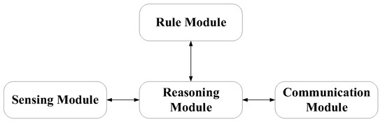
Figure 1.
The basic structure of the agent.
Multi-Agent System (MAS) contains multiple agents. The lower agents, the upper agents, and the agent clusters contain multiple information flows. Through cooperation and competition, the system as a whole achieves stability and optimization. The working efficiency of different multi-agent system structures is also different. At present, the most commonly used is the hybrid multi-agent structure, as shown in the Figure 2.
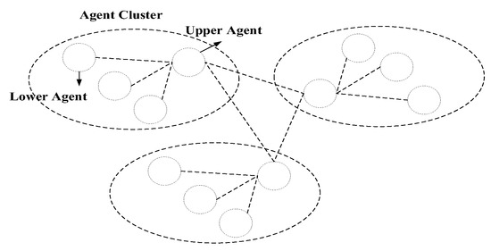
Figure 2.
Hybrid multi-agent architecture.
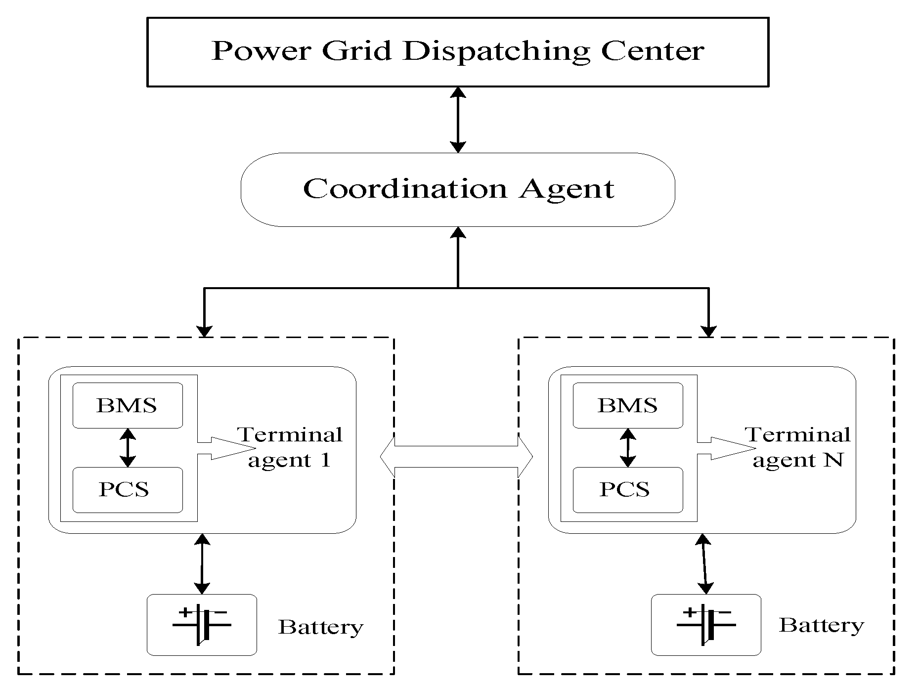
This paper uses the advantages of hybrid multi-agent architecture, combines the agent theory with distributed energy storage technology, and proposes a multi-agent collaborative control architecture for energy storage, as shown in Figure 3.
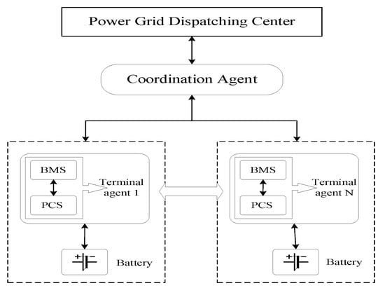
Figure 3.
Multi-agent collaborative control frame of the energy storage system.
On the one hand, the architecture has transformed and upgraded the distributed battery management system (BMS) into a terminal agent with active control and response functions. Each terminal agent controls the PCS active response frequency and voltage disturbance through the preset active control strategy. If the disturbance is not eliminated by the active control, the terminal agent will feed back relevant information to the coordinating agent and request cooperative control.
On the other hand, a coordination agent is set between the power grid and each terminal agent. On the one hand, the coordination agent selects the optimal interval through the preset algorithm and distributes the power grid dispatching instructions to the energy storage terminal agents; On the other hand, it accepts the request of the terminal agent and selects the appropriate terminal agent for cooperative control.
3. Active Control Strategy of Energy Storage Agent
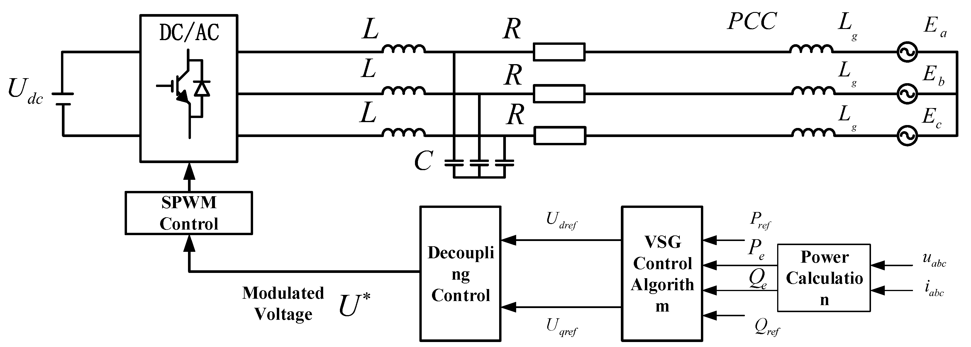
The energy storage device is connected to the power system through the power electronic converter and does not have damping characteristics and rotational inertia, so it lacks the inherent active frequency regulation and voltage regulation support capability of the conventional synchronous generator. In this paper, the virtual synchronous generator control technology is used here, and the damping, inertia, active frequency adjustment and reactive voltage regulation characteristics of the conventional synchronous generator are simulated through the additional improved control strategy of the energy storage inverter. On the basis of the conventional charging and discharging energy storage/release function, the energy storage agent can actively respond to the frequency and voltage disturbance adjustment function [20]. The control topology is shown in the Figure 4. Where is the power setting value; is the output (instantaneous) power; is the output voltage and current of VSG, and SPWM is sinusoidal pulse width modulation, which controls the on-off of switching devices in the inverter circuit.

Figure 4.
VSG control topology.
3.1. Frequency Control Strategy
Combined with the motion equation of the synchronous generator, set virtual damping and inertia to obtain the frequency adjustment control equation of VSG, as shown in the following equation.
where: is synchronous electrical angular velocity; is the electrical angular velocity; is the electrical angle; is the damping coefficient; is virtual inertia; Other parameters are the same as above; The relationship between electromagnetic torque and power is approximately: .
Laplace transform is performed on Equation (1), and then the term is shifted to obtain:
The frequency control block diagram is shown in Figure 5.
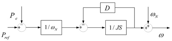
Figure 5.
Frequency control block diagram.
3.2. Voltage Control Strategy
VSG voltage control equation is:
where: is the voltage amplitude; is the output voltage amplitude; is the reactive voltage coefficient; is the reactive voltage integral coefficient, and other parameters are as above.
The voltage control block diagram of the virtual synchronous generator, according to Equation (3), is shown in Figure 6.
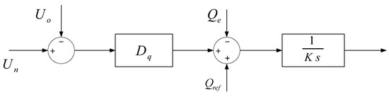
Figure 6.
Voltage control block diagram.
The VSG calculation process is as follows: the AC side collects the electric energy signal , calculates the active power, reactive power and other parameters through the power calculation, and calculates the output angular velocity of the VSG grid-connected system according to the frequency adjustment link, integrates it to obtain the phase angle , and the excitation potential amplitude is obtained through the voltage regulation link. is transformed by abc/dq coordinate system and combined with the virtual impedance link to obtain the voltage component. Then, the voltage component is decoupled through the voltage and current dual loop control loop to obtain the voltage control signal, which is used as the input signal for SPWM modulation, to obtain the control signal of the switch bridge in the converter. The voltage characteristics of the control energy storage AC side are the same as the power grid.
4. Multi-Agent Collaborative Control Strategy for Energy Storage
4.1. Energy Storage Agent Control Logic
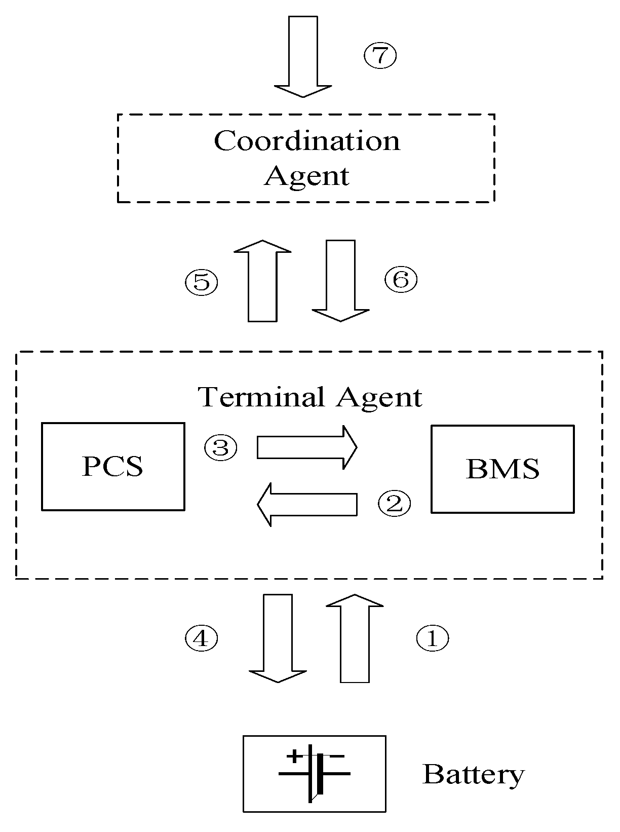
The control strategy of the energy storage agent proposed in this paper is mainly aimed at the terminal agent in the energy storage area, combining with particle swarm optimization algorithm to form a logical agent composed of coordination agent, terminal agent and battery body, as shown in the Figure 7 (taking a single battery as an example).

Figure 7.
Multi-energy storage agent collaborative control logic.
Among them, information flow ① includes information collected by BMS from the battery body, such as voltage, current, state of charge, etc.;
Information flow ② includes real-time information and historical data of battery body collected by BMS, collaborative control information, etc.;
Information flow ③ includes relevant information in PCS operation control;
Information flow ④ includes PCS active control information, etc.;
Information flow ⑤ includes real-time battery information, active control deviation information, coordinated control deviation information, etc.;
Information flow ⑥ includes energy storage output power demand information, collaborative control request information, etc.;
Information flow ⑦ includes power demand information of power grid dispatching center, etc.;
4.2. Multi-Energy Storage Agent Cooperative Control Algorithm
The preset collaborative control algorithm of the coordination agent is shown in the Figure 8.
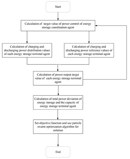
Figure 8.
Multi-energy storage agent cooperative control algorithm.
The algorithm is as follows:
- (1)
- Set the total control target value of the regional energy storage coordination agent according to the power grid dispatching requirements .
- (2)
- Calculate the initial power distribution value of each energy storage terminal agent:
When each energy storage terminal agent calculates the initial value of power distribution, it needs to know the information, such as the state of charge of the battery pack at the last time of each terminal agent.
When the power demand is positive, the initial value of discharge power distribution calculated by the ith terminal agent is:
where: , n is the number of terminal agents; is the state of charge of the battery pack of the ith energy storage terminal at the last moment.
- (3)
- Calculate the power reference value of each energy storage terminal agent:
Combined with the maximum charging and discharging power allowed by the energy storage PCS, the power reference value of the energy storage terminal agent is:
where: is the maximum allowable charging and discharging power of the ith energy storage terminal intelligent agent PCS; is the power adjustment factor.
Compare the initial power distribution value of the energy storage terminal agent with the maximum allowable charge and discharge power. If the initial power distribution value is greater than the maximum allowable charge and discharge power, then ; If the initial value of power distribution is less than the maximum allowable charge and discharge power, then :
- (4)
- Determine the output power target value of each energy storage terminal agent:
From the above equation, the output power target value of the ith energy storage terminal agent is , and there are two possibilities:
If the initial value of power distribution is greater than the maximum allowable charge and discharge power, the intellectual output of the energy storage terminal has reached the limit value but has not reached the initial value of power distribution, and there is a deviation. The calculation equation of the total power deviation is:
If the initial value of power distribution is less than the maximum allowable charge and discharge power, the output target value of the energy storage terminal agent reaches the initial value of coordination agent distribution, and there is still margin for additional adjustment. The calculation formula of the power margin of the ith energy storage terminal agent is:
The energy storage terminal intelligent agent with power margin and the state of charge not reaching the limit will increase the additional power redistributed on the original basis. The total control target value of the energy storage coordination intelligent agent will be set as the total power deviation, and the values will be updated according to Equations (4) to (8).
The objective function set by the algorithm is shown in Equation (9), and Equation (10) and Equation (11) are the calculation conditions related to the objective function.
where: is the calculated power difference between the total charging and discharging power of the energy storage station and the total regulating command power; is the difference between the regulated state of charge of the energy storage station and the preset state of charge; is the charging and discharging power for the ith energy storage terminal agent; is the preset state of charge of the battery pack; is the adjustment time; is the energy storage capacity of the ith energy storage terminal agent; is the weight coefficient, which is used to measure whether the energy storage station is inclined to adjust the state of charge or to track and dispatch. The position of particles in the algorithm is expressed by the charging and discharging power of each energy storage terminal agent, and the speed of particles is expressed by the corresponding state of charge of each energy storage terminal.
The above objective function consists of two parts: one is to minimize the deviation between the total charging and discharging power of the energy storage system and the target value of the total regulation command (where the power deviation is expressed as the per-unit value); The other part is to minimize the deviation between the adjusted state of charge of each distributed energy storage system and the preset ideal state of charge. After continuous iterative optimization using particle swarm optimization, the total output of each energy storage agent approaches the target value of the total regulation command, and the adjusted state of charge of each distributed energy storage agent has the smallest deviation from the preset ideal state of charge.
4.3. Influencing Factors of Collaborative Control
In the actual operation of power grids, the condition of network communication is an important factor that affects the effectiveness of multi-agent collaborative control. At the same time, in the new smart grid, the communication carrier for multipoint distributed energy storage is mainly optical fiber, with high communication reliability. Therefore, the default communication delay between agents in this article is within the allowable error range, regardless of the impact of communication exceptions on the control effect of multiple agents, to ensure the timeliness and effectiveness of information transmission. The entire station communication adopts a dual network redundancy communication arrangement. The station control level communicates with the upper dispatching center data network through gateway, switches, and longitudinal encryption. The station control level is connected to the bay level, the bay level to the process level, and each agent through optical fiber. The IEC 61850 communication protocol is adopted. The specific communication method and architecture are shown in the Figure 9.
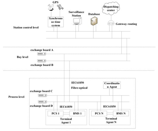
Figure 9.
Communication architecture.
On the other hand, the multi-energy storage agent collaborative control algorithm proposed in this paper allocates the regulation demand based on the state of charge and the maximum allowable charge and discharge power of each energy storage unit, which can enable each energy storage unit to fully exert its own regulation ability, achieve a balanced output, effectively guarantee the service life of the equipment, and promote the smooth operation of the actual power grid.
5. Analysis of Numerical Examples
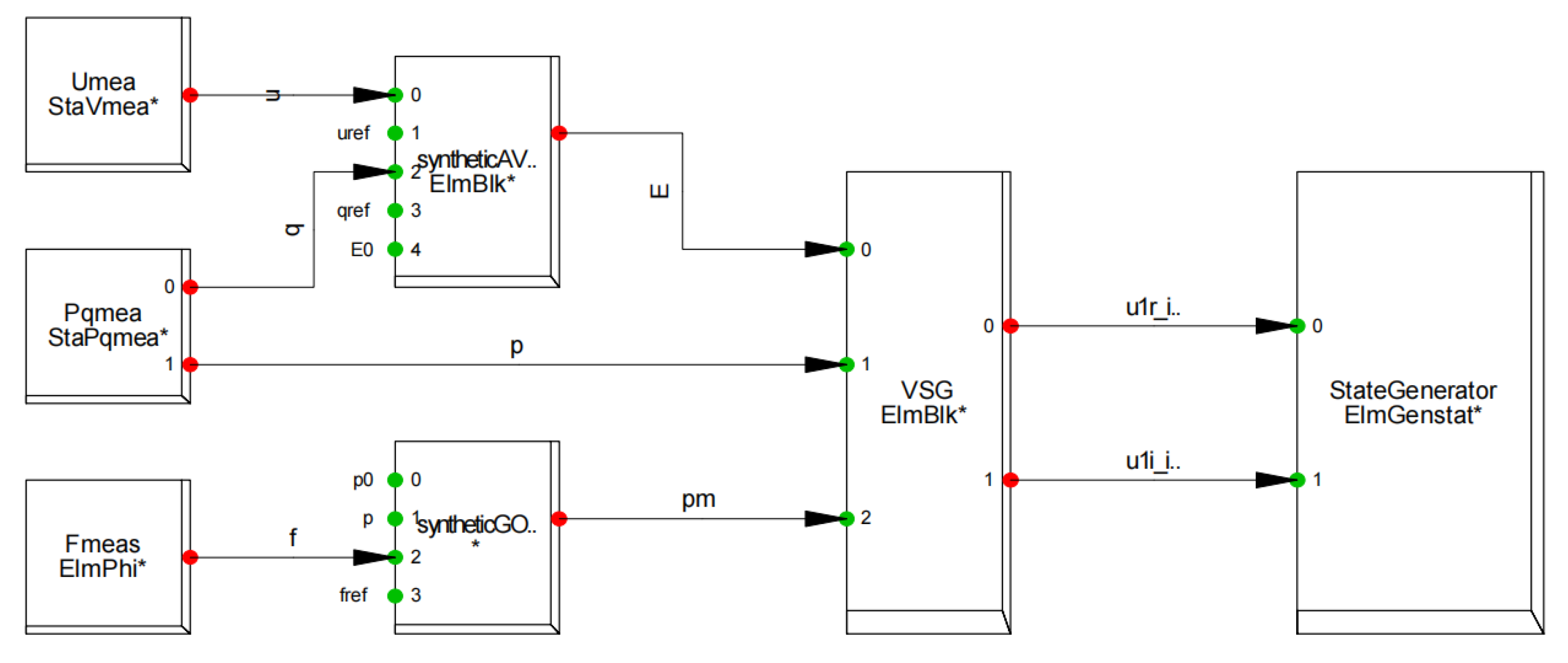
Based on the aforementioned cooperative control strategy and algorithm of multiple energy storage agents, the power system simulation model, including multi-point distributed energy storage, is established using DIgSILENT simulation software. The system includes photovoltaic, energy storage, synchronous motor and load. Nodes 2 and 3 are, respectively, connected with photovoltaic and energy storage devices, node 1 is connected with synchronous motor and energy storage devices, and nodes 5, 6 and 8 are connected with the load. The example simulation system is shown in Figure 10, the VSG block diagram of the energy storage agent in DIgSILENT is shown in Figure 11 (the control quantities in the figure have been described in Section 3.1) and node parameter settings are shown in Table 1.
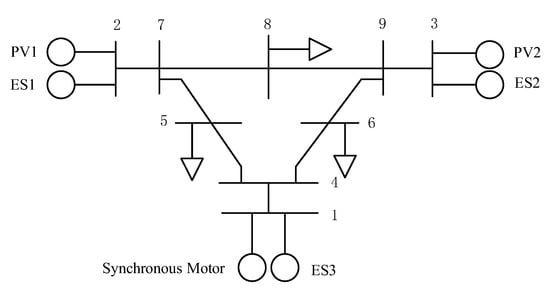
Figure 10.
Example of the simulation system.
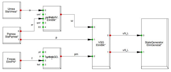
Figure 11.
Implementation of VSG model based on DIgSILENT.

Table 1.
Node parameter settings.
When the optical storage unit does not apply the virtual synchronization control strategy, the circuit breaker at node 8 trips due to fault, and the circuit breaker has no subsequent action in 1 s, and the system frequency is set to the standard unit value based on 50 Hz. At this time, the dynamic response characteristics of the system frequency and voltage are shown in Figure 12 and Figure 13.
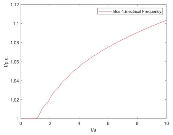
Figure 12.
Dynamic response characteristics of frequency (VSG not considered).

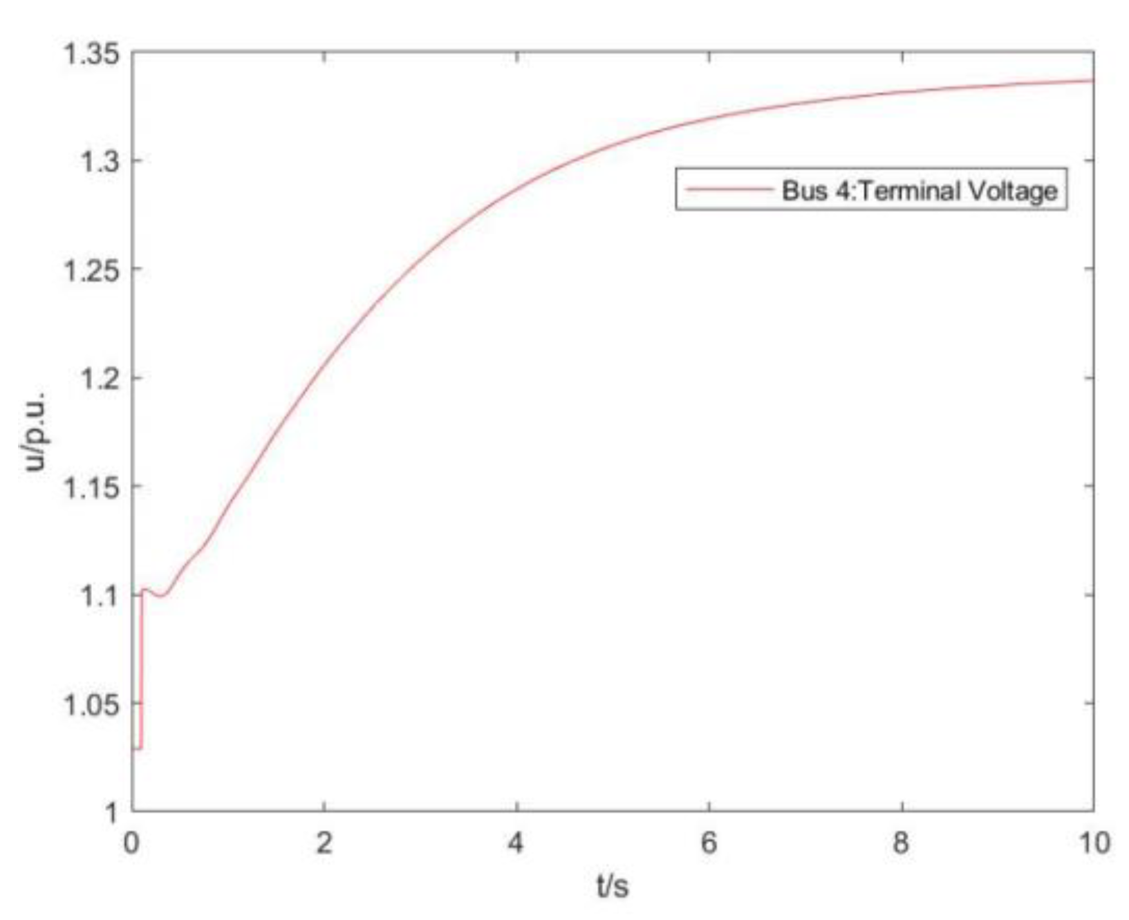
Figure 13.
Voltage changes of key nodes in the system (VSG not considered).
As can be seen from Figure 12, when the circuit breaker at node 8 trips due to fault and the circuit breaker has no subsequent action in 1 s, the system frequency continues to rise in 10 s and does not return to a stable state.
As can be seen from Figure 13, the voltage at Bus 4 increases rapidly after 1 s and tends to stabilize after about 10 s, with a stable value of 0.32 p.u. higher than the initial value.
When the optical storage unit applies the virtual synchronization control strategy, the circuit breaker at eight nodes trips due to a fault and the circuit breaker does not act subsequently, and the system frequency is set to the unit value based on 50 Hz. At this time, the dynamic response characteristics of the system frequency and voltage are shown in Figure 14 and Figure 15.
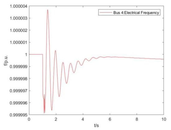
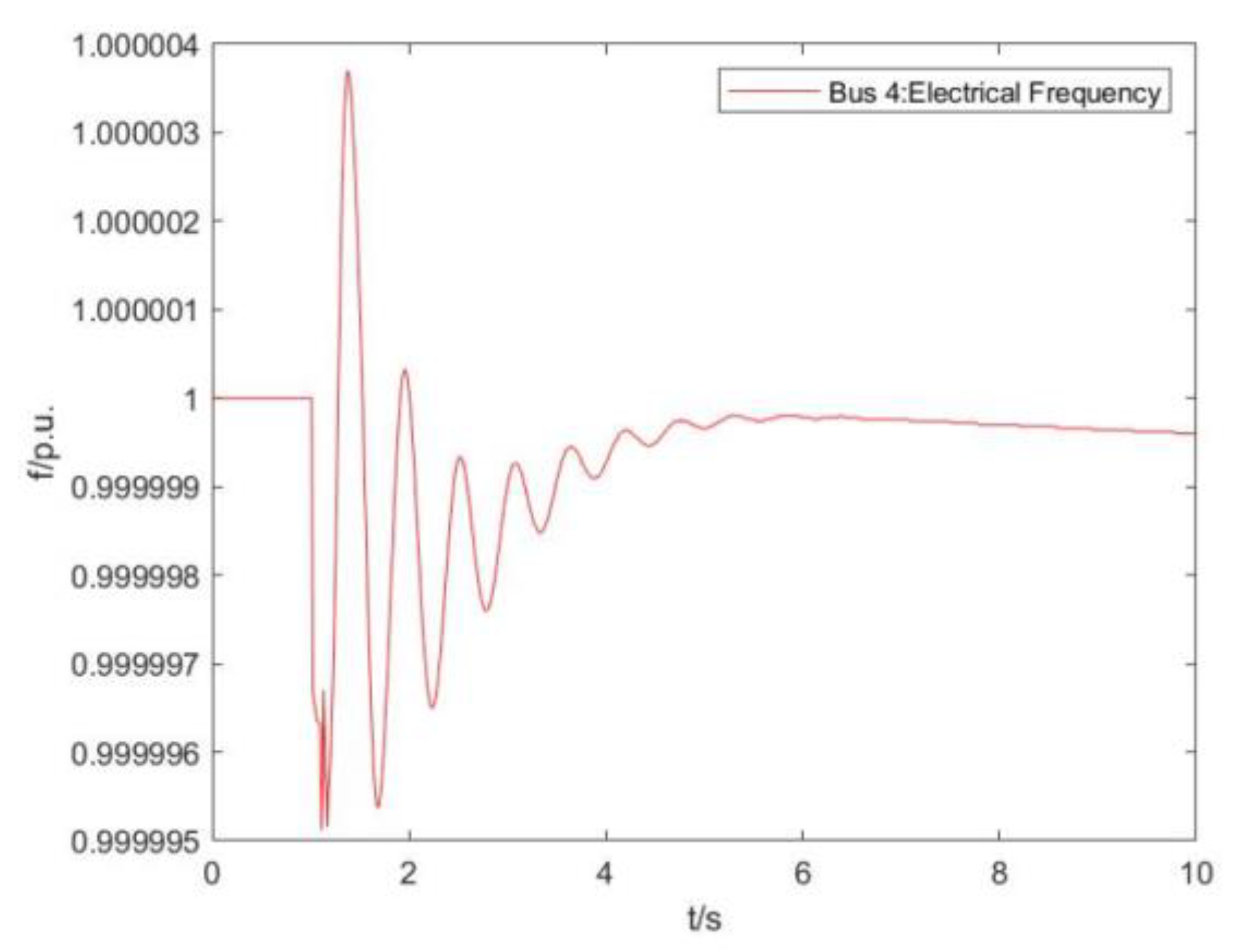
Figure 14.
Frequency changes of key nodes in the system (consider VSG only).
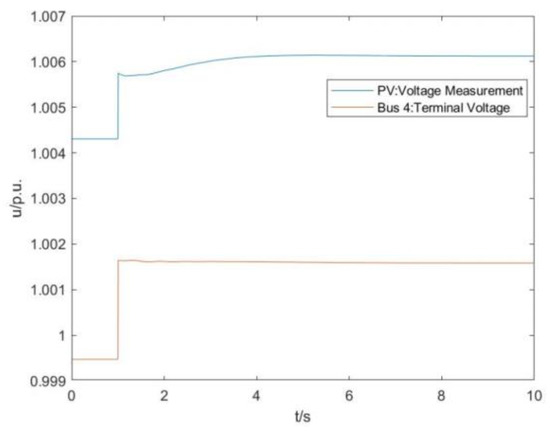
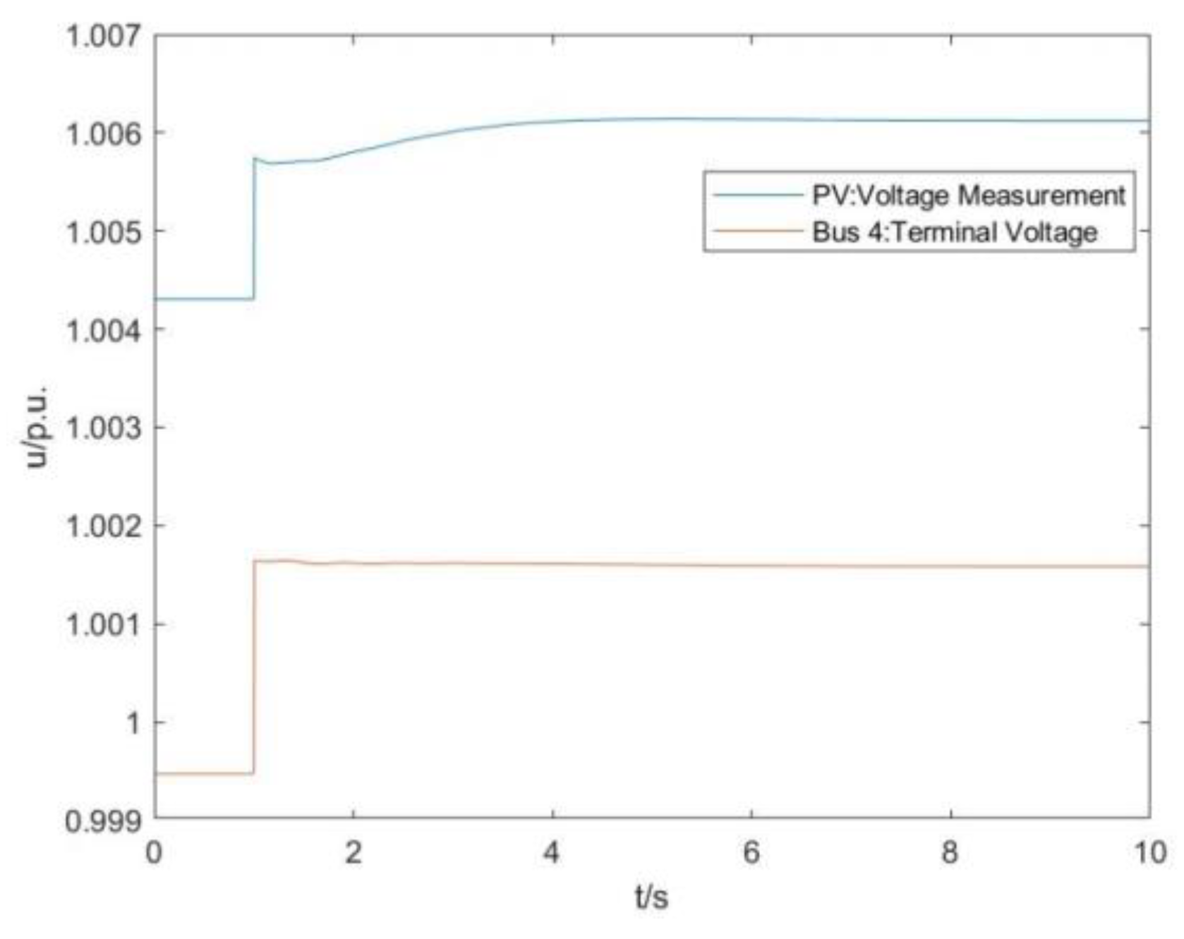
Figure 15.
Voltage changes of key nodes in the system(consider VSG only).
It can be seen from Figure 14 that the frequency of the system oscillates after 1 s and then tends to stabilize after about 8 s, and the stable value is 0.0001 Hz lower than the initial value. When the virtual synchronization control strategy is applied, the system frequency can oscillate and stabilize after the failure, and the frequency fluctuation range is small.
It can be seen from Figure 15 that the voltage at PV 1 increases rapidly to 1.0057 p.u. after 1 s and then recovers to stability after about 8 s. The stabilized voltage is 0.0018 p.u. higher than the original voltage. The voltage at Bus 4 rose rapidly to 1.0017 p.u. after 1 s and then stabilized after about 8 s. The stabilized voltage was 0.002 p.u. higher than the original voltage. When the virtual synchronization control strategy is applied, the voltage fluctuation range of the system is smaller than that without the virtual synchronization control strategy, and it can recover stability in a certain time.
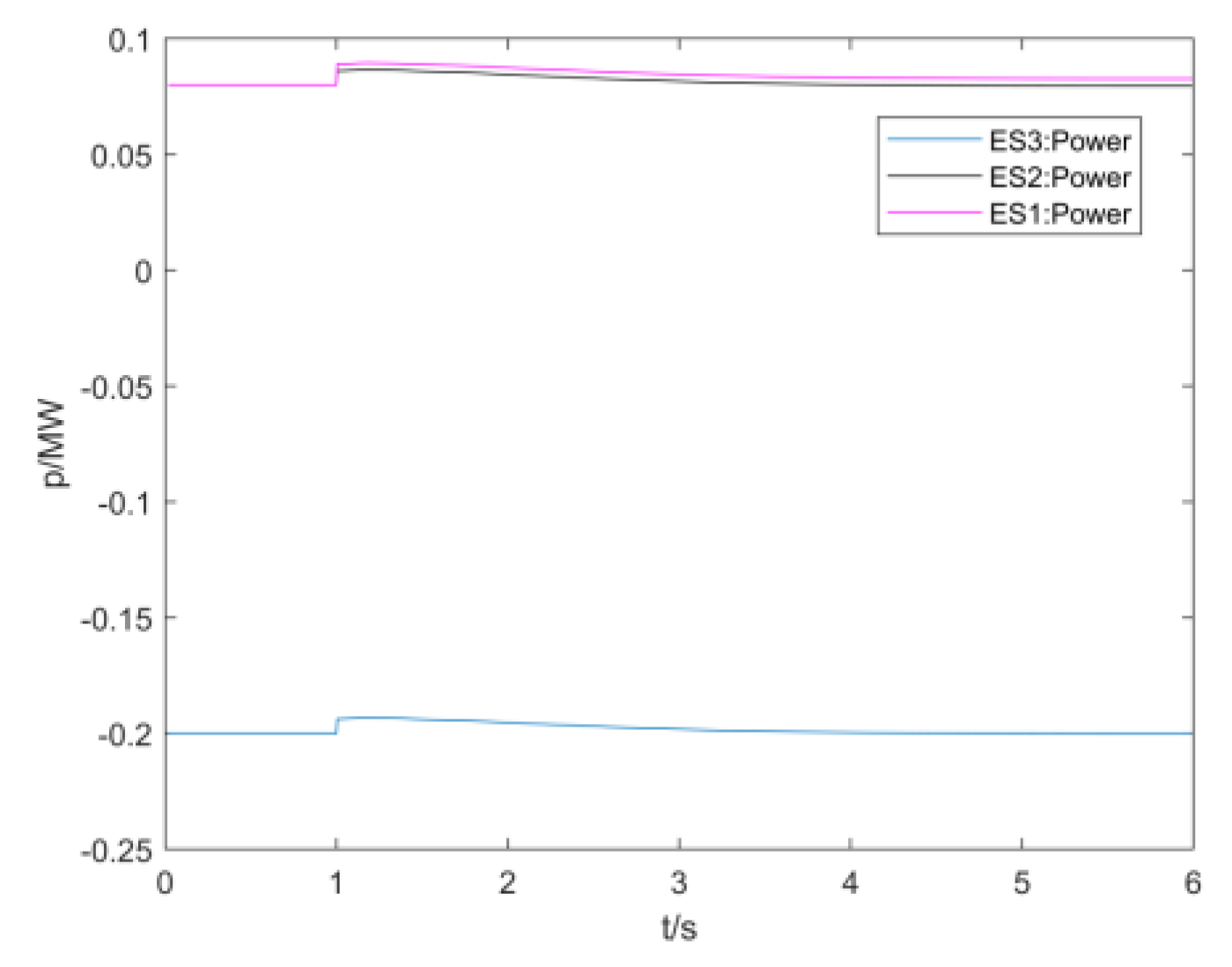
As can be seen from Figure 16, the power of ES1, 2, and 3 rapidly increases by about 0.006 MW at 1 s and recovers to the initial value after about 3 s. When a disturbance occurs in the system, each energy storage terminal agent actively adjusts the power output by the energy storage agent to provide fast frequency support.
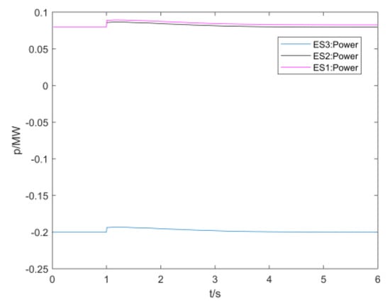
Figure 16.
Discharge characteristics of each energy storage (consider VSG only).
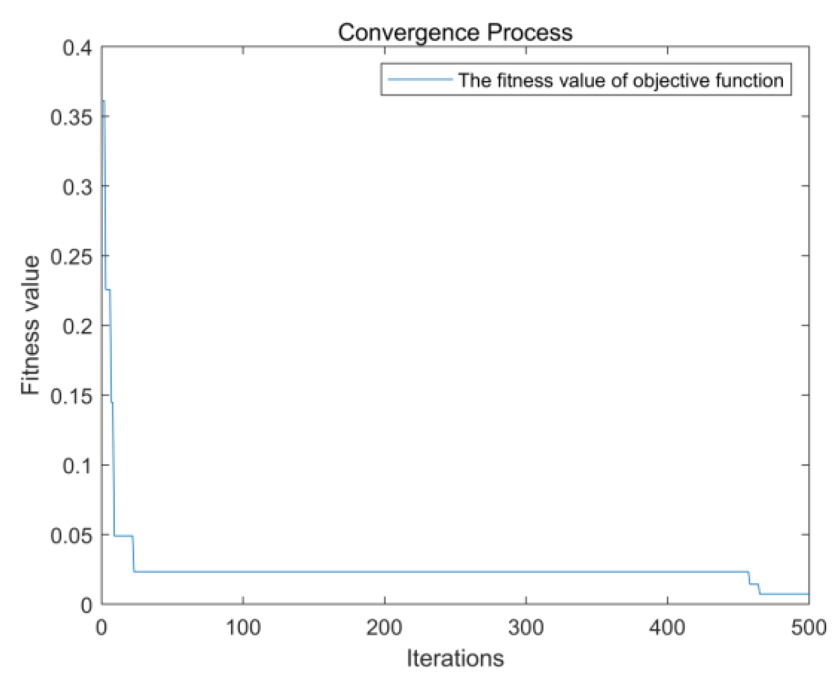
At this time, multiple energy storage agents cooperate to control the function action and start to conduct secondary adjustments to make up for the adjustment deviation of primary active control. The weight coefficient in the cooperative control algorithm of multiple energy storage agents ranges from 0 to 1, the maximum charging and discharging power of energy storage are limited to 0.2 MW, and the upper and lower limits of the SOC of energy storage are 0.1 to 0.8. After many iterations, the optimal value of 0.006036 is obtained and the iterative convergence process of the fitness function is shown in Figure 17
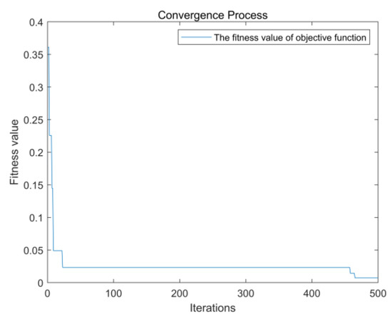
Figure 17.
Particle swarm algorithm iteration diagram.
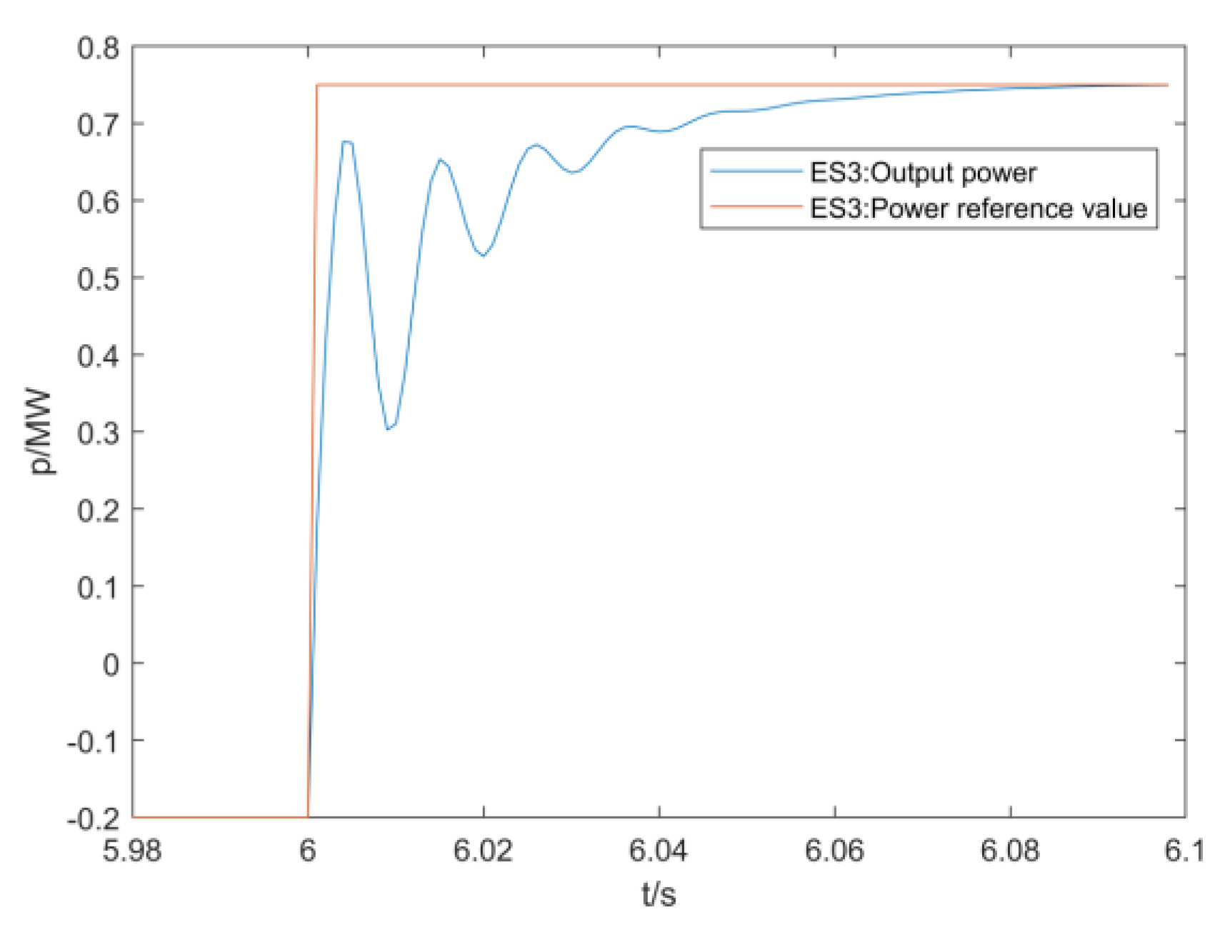
With reference to the relevant requirements in the fast frequency response standard for new energy stations in Northwest China Power Grid, the frequency response time of secondary regulation is set in 2 s, and the frequency deviation dead band is 50 ± 0.01 Hz. After the first active control is stable for 6 s, the calculated power regulation command value is input into each energy storage unit in the form of a parameter event. The power reference value Pref of energy storage, the output power P (taking energy storage three as an example), and the frequency changes of key nodes of the system are shown in the following figures, where the system frequency is set to the standard unit value based on 50 Hz.
In Figure 18, after setting the parameter event, the power reference value of energy storage three suddenly changes to 0.75 MW at 6 s, and the output power oscillates and increases, becoming equal to the reference value at 6.08 s. From the adjustment process of energy storage 3, it can be seen that each energy storage operates according to the power adjustment amount calculated by the collaborative control algorithm, achieving a support effect on the system frequency.
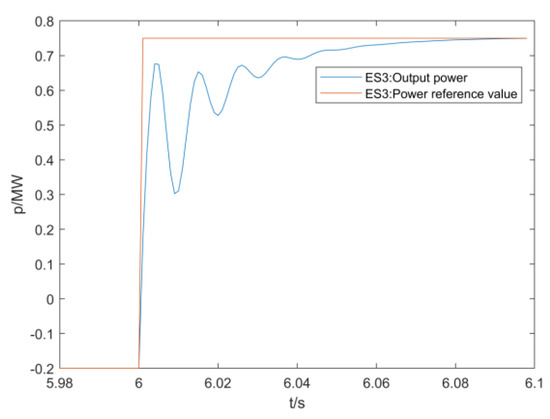
Figure 18.
Response characteristic of discharge power of ES3.
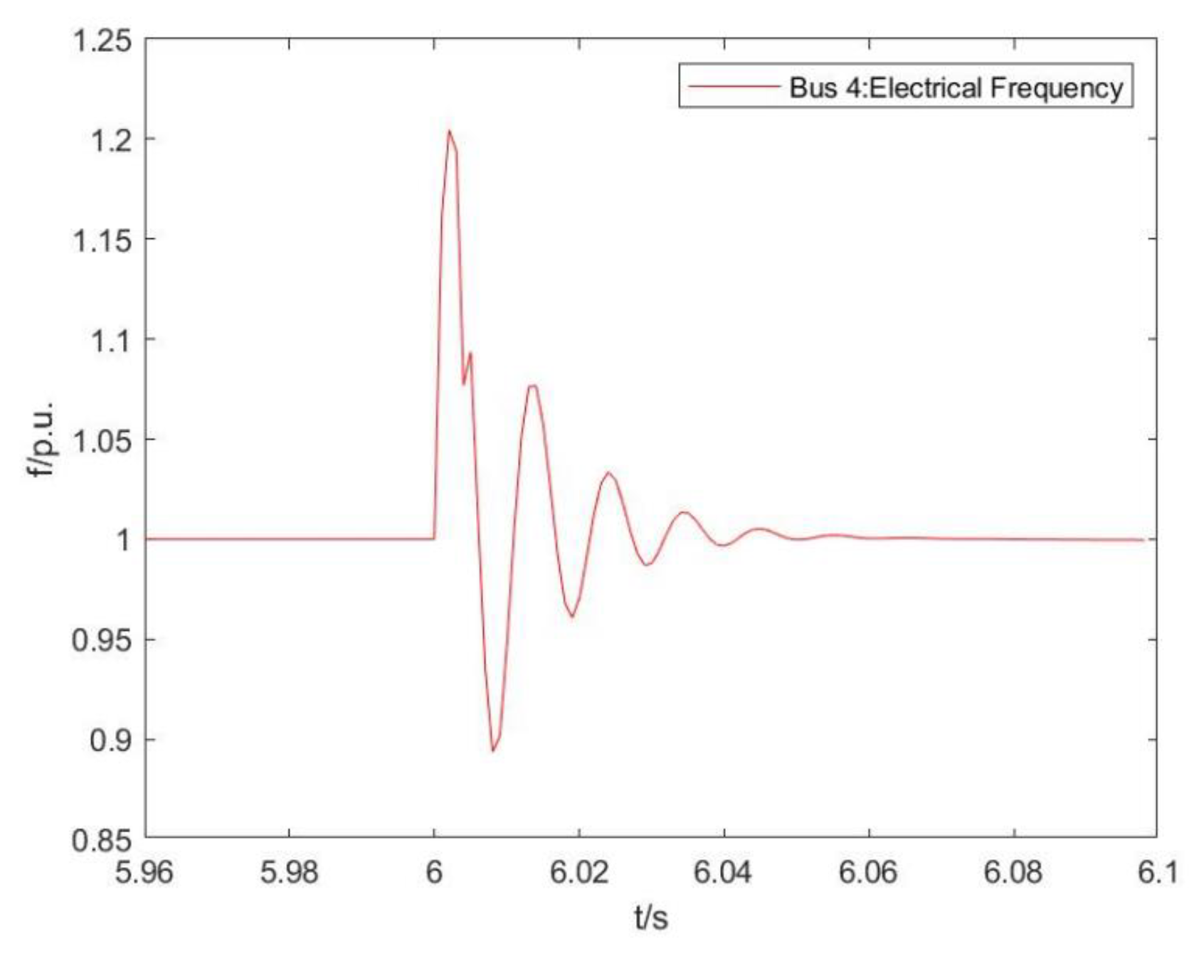
In Figure 19, the frequency of the key nodes of the system is shown in the form of a unit value. The frequency oscillates after 6 s and recovers to stability at 6.09 s. The stabilized frequency is 1.005 p.u. The response time and frequency deviation is in line with the standards set in the previous article, with a good adjustment effect.
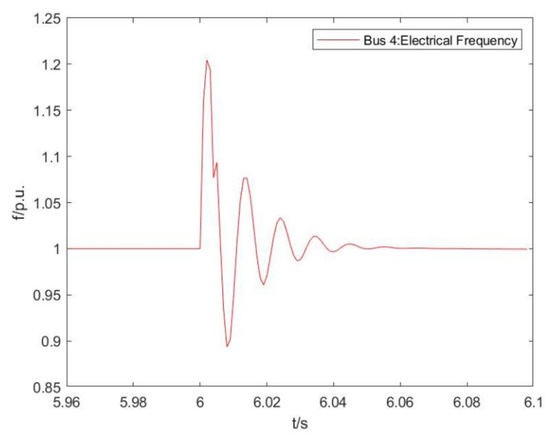
Figure 19.
Response characteristics of frequency (consider VSG and collaborative control).
It can be seen from the following three situations: the optical storage unit does not apply the virtual synchronization control strategy, the virtual synchronization control strategy, the virtual synchronization control strategy and the cooperative control strategy: when the virtual synchronization control strategy is not applied, when the open circuit fault occurs, and the fault is not cleared, the system frequency does not return to stability, and the system voltage fluctuates greatly. When the virtual synchronization control strategy is applied, the system voltage fluctuation range is small, the system frequency response time is shortened, and the stabilized frequency deviation is smaller, but it still does not meet the standards set in this paper. When the virtual synchronization control strategy and cooperative control strategy are applied, the system frequency response time is greatly shortened, and the stabilized frequency deviation meets the standards set in this paper.
6. Conclusions
In this paper, a multi-agent cooperative control strategy for distributed energy storage systems is proposed considering that the energy storage system can suppress the fluctuation of renewable energy. On the one hand, the strategy is based on the idea of the virtual synchronous generator to propose an active control strategy to actively respond to the disturbance of the system and realize the active control; On the other hand, a cooperative control strategy is proposed based on the idea of multi-agent cooperative control. The multi-agent particle swarm optimization algorithm is used to establish the objective function of the control strategy, find the optimal solution, and send the relevant power regulation instructions to the terminal energy storage agent to achieve cooperative control. The simulation results show that the proposed distributed energy storage control strategy can effectively reduce the frequency fluctuations of the new power system with renewable energy as the main body and ensure the smooth operation of the system. However, this paper does not give a control strategy considering the access location of distributed energy storage, which needs further research.
Author Contributions
Conceptualization, T.S. and L.Q.; Methodology, T.S. and L.Q.; Software, X.Q. and L.Q.; Validation, X.Q.; Formal analysis, T.S. and X.Q.; Data curation, T.S.; Writing—original draft, X.Q. and C.T.; Writing—review & editing, T.S., X.Q. and C.T.; Project administration, T.S.; Funding acquisition, T.S. All authors have read and agreed to the published version of the manuscript.
Funding
This research was funded by the Project of the National Natural Science Foundation for Regional Innovation and Development Joint Fund (No. U22A20226).
Data Availability Statement
Not applicable.
Conflicts of Interest
The authors declare no conflict of interest.
Nomenclature
| MAS | Multi-Agent System |
| ES | Energy Storge |
| BMS | Battery management system |
| PCS | Power conversion system |
| VSG | Virtual synchronous generator |
| SPWM | Sinusoidal pulse width modulation |
| DC | Direct current |
| AC | Alternating current |
| Direct voltage | |
| PV | Photovoltaic |
| P/p | Active power |
| Q/q | Reactive power |
| p.u. | Per unit |
| Hz | Frequency unit |
| SOC | State of charge |
| MW | Active power unit |
| Mvar | Reactive power unit |
| L | Inductance |
| R | Resistance |
| C | Electric capacity |
| PCC | Point of common coupling |
| Pref | Active power setting value |
| Output active power of virtual synchronous generator | |
| Output reactive power of virtual synchronous generator | |
| Output voltage of virtual synchronous generator | |
| Inductance | |
| A-phase potential | |
| B-phase potential | |
| C-phase potential | |
| Output current of virtual synchronous generator | |
| Modulated voltage | |
| Damping coefficient | |
| Virtual inertia | |
| The electromagnetic torque | |
| Output potential | |
| Reactive voltage coefficient | |
| Voltage amplitude | |
| Output voltage amplitude | |
| Reactive voltage integral coefficient | |
| abc/dq | Park’s Transformation |
| Total power control target value | |
| Initial value of power distribution | |
| n | The number of terminal agents |
| The state of charge of the battery pack of the ith energy storage terminal at the last moment | |
| The power reference | |
| The maximum allowable charging and discharging power | |
| The total power deviation | |
| The power margin | |
| The output power target value | |
| Objective function | |
| min | Minimum |
| The power difference between the charging and discharging power of the energy storage station at the last moment and the target value | |
| The difference between the regulated state of charge of the energy storage station and the preset state of charge | |
| The charging and discharging power of the ith energy storage terminal agent at the last moment | |
| The adjustment time | |
| The energy storage capacity of the ith energy storage terminal agent | |
| The preset state of charge of the battery pack | |
| Bus | Generatrix |
| Electrical angular velocity | |
| Synchronous electrical angular velocity | |
| Electrical angle | |
| The power adjustment factor | |
| The power adjustment factor | |
| The weight coefficient | |
| The weight coefficient | |
| IEC | International Electro technical Commission |
References
- Xue, C. Photovoltaic Power Generation Problem and Its Influence on Power System. Electron. Technol. Softw. Eng. 2019, 14, 229–230. [Google Scholar]
- Yuanyuan, S.; Shurong, L.; Fang, S.; Hengxu, Z. Responsibility Division of Multiple Harmonic Sources in Distribution Networks with Distributed Harmonic Sources. Proc. CSEE 2019, 5389–5398, 5586. [Google Scholar]
- Lihong, M.; Yu, X.; Guanghai, N.; Haisheng, W.; Sifan, L.; Yi, L. Research on Distributed Generation Optimization Configuration Considering Virtual Power Plant in Distribution Network. Electr. Drive 2022, 14, 74–80. [Google Scholar]
- Weiping, Y.; Zhijun, E.; Ning, Z.; Bangyu, Y.; Wei, L.; Chen, L. Research on Energy Management of Photovoltaic Hybrid Energy Storage System. Renew. Energy Resour. 2021, 2, 264–269. [Google Scholar]
- Zhicheng, L.I.; Daogang, P.E.; Huirong, Z.H.; Danhao, W.A.; Yuchen, L.I. Development Prospects of Energy Storage Participating in Auxiliary Services of Power Systems Under the Targets of the Dual-carbon Goal. Energy Storage Sci. Technol. 2021, 4, 70–82. [Google Scholar]
- Yu, C.H.; Wu, J.P.; Yang, H.J.; Li, Z.H.; Teng, X.L.; Tu, M. Frequency Regulation Strategy for Power Grid Incorporating Large-scale Energy Storage. Electr. Power Eng. Technol. 2019, 4, 68–73. [Google Scholar]
- Yi, Z.; Yi, D.; Yingying, G.; Lixin, J. Control Strategy of Energy Storage in Primary Frequency Regulation of Power Grid Considering Dead Band and State of Charge. Sci. Technol. Eng. 2022, 11, 4391–4399. [Google Scholar]
- Yongheng, L.; Xiaotian, H.; Lei, W.; Jingwen, Y. Research on Frequency Modulation Control Strategy of Photovoltaic Grid Connection Based on Fuzzy Control. Jilin Electr. Power 2022, 50, 1–4. [Google Scholar]
- Gangui, Y.; Ying, L.; Shuangming, D.; Hongbo, L.; Gang, M.; Junhui, L. Power Distribution Strategy for Battery Energy Storage Unit Group Participating in Secondary Frequency Regulation of Power System. Autom. Electr. Power Syst. 2020, 14, 26–34. [Google Scholar]
- Zhijie, Q.; Linchao, M. Research on Large-scale Energy Storage Control Strategy for Power System Stability Improvement. High Volt. Appar. 2022, 58, 75–84+91. [Google Scholar]
- Ping, Y.; Zhuo, C.; Ting, L.; Jiawen, Z.; Bolin, L.; Xiangping, C. A Control Method of Photovoltaic Power Generation and Hybrid Energy Storage Based on VSG. Power Syst. Clean Energy 2023, 39, 83–91+113. [Google Scholar]
- Wan, C.; Qian, W.; Zhao, C.; Song, Y.; Yang, G. Probabilistic Forecasting Based Sizing and Control of Hybrid Energy Storage for Wind Power Smoothing. IEEE Trans. Sustain. Energy 2021, 12, 1841–1852. [Google Scholar] [CrossRef]
- Yang, Q.F.; Wang, C.Q.; Wei, J.H. Capacity Allocation of Energy Storage System for Improving Grid Inertia and Primary Frequency Regulation. Electr. Power Constr. 2020, 41, 116–124. [Google Scholar]
- Hua, S.; Jiantao, S.; Jiangfeng, Z.; Liling, G.; Ye, G.; Xinwei, S. Review on Planning and Bidding Strategy of Energy Storage Considering Frequency Regulation. Electr. Power Autom. Equip. 2021, 9, 191–198. [Google Scholar]
- Li, W. Research on Hybrid Energy Storage Capacity Configuration of Island-type Wind-solar Complementary Microgrid. Matster’s Thesis, Xi’an University of Science and Technology, Shaanxi, China, 2019. [Google Scholar]
- Meiqin, M.; Jialing, H.; Liuchen, Z. Energy Storage Optimization Allocation Method Considering Photovoltaic Output Prediction Error Correction. ACTA Energ. Sol. Sin. 2021, 2, 410–415. [Google Scholar]
- Wei, Z.E.N.G.; Xiong, J.; Suliang, M.A.; Yuliang, T.A.N.; Jianlin, L.I. Research on Control Method of Distributed Energy Storage System to Improve Photovoltaic Consumption. Energy Storage Sci. Technol. 2022, 11, 3268–3274. [Google Scholar]
- Chen, Z.; Sun, Y.; Zhang, Y.; Li, M.C.; Zhang, D.L.; Xiao, W. Research on Energy Storage Optimal Allocation Considering Complementarity of Wind Power and PV. Trans. China Electrotech. Soc. 2021, 1, 145–153. [Google Scholar]
- Qingzhi, Y.; Wei, J.; Chunlei, X. Monitoring Design and Research on Hierarchical Control of AC/DC Hybrid Microgrid Based on Multi-agent. High Volt. Eng. 2020, 7, 2327–2339. [Google Scholar]
- Li, Z.-X.; Qiu, X.; Han, W.-Y. Simulation Research on Virtual Synchronization Control Strategy of Optical Storage Integration Based on DIgSILENT Platform. In Proceedings of the 2021 IEEE Sustainable Power and Energy Conference (iSPEC), Nanjing, China, 23–25 December 2021; pp. 1133–1137. [Google Scholar]


Disclaimer/Publisher’s Note: The statements, opinions and data contained in all publications are solely those of the individual author(s) and contributor(s) and not of MDPI and/or the editor(s). MDPI and/or the editor(s) disclaim responsibility for any injury to people or property resulting from any ideas, methods, instructions or products referred to in the content. |
© 2023 by the authors. Licensee MDPI, Basel, Switzerland. This article is an open access article distributed under the terms and conditions of the Creative Commons Attribution (CC BY) license (https://creativecommons.org/licenses/by/4.0/).