Article

Improvement of Relative DEM Time Step Range in Fast Fluidization Simulation of Type-A FCC Particles

1
School of Mathematics and Statistics, Chongqing Three Gorges University, Chongqing 404020, China
2
State Key Laboratory of Plateau Ecology and Agriculture, Qinghai University, Xining 810016, China
3
College of Computer Science, Guangdong University of Science & Technology, Dongguan 523083, China
4
Department of Information Technology, Hazara University, Mansehra 21300, Pakistan
*
Author to whom correspondence should be addressed.
Processes 2023, 11(4), 1155; https://doi.org/10.3390/pr11041155
Submission received: 14 March 2023 / Revised: 6 April 2023 / Accepted: 6 April 2023 / Published: 10 April 2023
(This article belongs to the Special Issue 10th Anniversary of Processes: Women's Special Issue Series)

Abstract

:
In many process engineering fields, gas-particle fluidized beds are widely used. In fluidized bed research, the discrete element method, or DEM, has been a powerful tool for design and operation purposes. However, with the use of Type-A powders, fluid catalytic cracking or FCC particles being classical cases, they have hardly been reported in DEM simulations of fast fluidization. This study paid close attention to the suitable selection of a stiffness constant and a DEM time step. To reflect their respective effects and complicated interactions, a so-called relative DEM time step was defined. The drag coefficient was correlated using the energy-minimization multi-scale (EMMS) approach to reasonably calculate the gas–solid interaction. Six representative cases with different relative time step values were chosen to simulate a micro-fluidized bed of Type-A FCC powders. The results showed that DEM employing EMMS-based drag force was able to greatly enlarge the suitable range of relative time steps in a fast fluidization simulation of Type-A powders. In addition, the typical macro flow structures of fast fluidization was successfully captured: axially dilute in the top and dense in the bottom, and radially dilute in the core and dense near the wall. Moreover, the distinct gas–solid backmixing, which is considered one of the most important pieces of evidence for the determination of fast fluidization regimes, was modeled. It was indicated that the EMMS-based drag model attenuated the overestimated drag force so that the soft-sphere contact model would be able to more appropriately deal with particle collision, and thus improve the suitable relative DEM time step range.

1. Introduction

Gas–solid fluidized beds are widely applied in environment, energy, chemical engineering and other process engineering fields [1]. Numerical simulations have already become complementary research means to improve our understanding of the fluidization dynamics. As the discrete element method (DEM) [2,3,4,5] is advantageous for providing particle-level information, it is a desired tool in fluidized bed researches for design and operation purposes. Nowadays, more and more DEM simulation studies have been carried out on different fluidized regimes of different particle types.
Although there are different criteria for particle clarification, the traditional one given by Geldart [6] is widely accepted. According to density difference and mean particle size, particle groups fall into four clearly recognizable types. They are: A-Type, with particle sizes smaller than 100 um and particle densities of no more than 1400 kg/m3; B-Type, with sizes from 40 um to 500 um and densities ranging from 1400 to 4000 kg/m3; C-Type, with sizes smaller than 30 um; and D-Type, with sizes bigger than 600 um. The fluidized properties vary across different particle types. C-Type (or ultra-fine) particles are usually considered difficult to fluidize. D-Type (or ultra-coarse) particles are just fluidizable. B-Type (or coarse) particles are more suitable for fluidization than C- and D-Type particles. A-Type (or fine) particles are generally thought to be most fluidizable. Fluid catalytic cracking (FCC) particles can be typical examples of A-type fluidized materials. They exhibit unique behaviors, such as a high gas–solid mass transfer rate, a high bed expansion ratio and a high heat transfer rate. Furthermore, they expand considerably before bubbling commences. Moreover, their cohesion is stronger, and, usually, van der Waals forces should not be negligible.
There are two obvious flaws in DEM simulations of gas–solid fluidized beds: (1) Although A-Type particles are generally thought to be most fluidizable, most DEM simulation researches uses B- or D-Type particles; and (2) the most suitable operation regime for A-Type powders, such as typical FCC particles, is high-speed fast fluidization, but the use of A-Type powders has hardly been reported in DEM simulations of fast fluidization. Therefore, in this regard, the references are limited to studies on low-speed classical fluidization [7,8,9,10,11,12,13,14,15,16,17,18,19,20,21,22]. As is known, low-speed bubbling fluidized beds are relatively easy to model by the use of DEM. The DEM methodological basis was provided by the original studies [2,3,4], which validated DEM for simulations of bubbling fluidized beds. However, the most suitable regime for A-Type powders is not bubbling, but fast fluidization.
As for the high speed fluidization of Type-A powders, a micro-fluidized bed of Type-A FCC powders was studied by us using an EMMS-based drag coefficient [23]. However, as an early exploratory study, it did not consider the effect of the stiffness constant or the DEM time step. To reflect their respective effects and complicated interactions, a so-called relative DEM time step was defined by us in [24]. By using a traditional DEM, the suitable combinational parameter values of the stiffness constant and the DEM time step were determined. Unfortunately, the suitable range of relative time step proved to be so limited that one could hardly make a convenient choice of combinational values for the stiffness constant and the DEM time step. Moreover, both gas backmixing and solid backmixing were inconspicuous, and were only occasionally present in the previous two studies. Worse, our two previous studies failed to model the indicative macro-structures of fast fluidization, such as the dilute-core/dense-wall and dilute-top/dense-bottom structures.
Thus, two problems have arisen. One is whether DEM can appropriately model fast fluidization of Type-A powders. The other is how to choose the suitable the combinational parameters of the stiffness constant and the DEM time step. In this article, we intended to solve both problems. We chose six representative cases with different relative time step values for the purpose of simulating a micro-fluidized bed of Type-A FCC powders. From the selected cases, the upper and lower bounds of the suitable relative time step were determined. Additionally, the typical macro-flow structures of fast fluidization were captured. Moreover, distinct gas–solid backmixing was modeled, which is considered as one of the most important pieces of evidence for the determination of a fast fluidization regime.

2. Simulation Methods

The governing Navier–Stokes equations for the gas phase were determined by the following two equations.
( ε g ρ g ) t + ( ε g ρ g u ) = 0
( ε g ρ g u ) t + ( ε g ρ g u u ) = ε g p S p ( ε g τ g ) + ε g ρ g g
where p , u and τ g are gas pressure, gas velocity and viscous stress tensor, respectively. Here, S p is the source term, calculated as
S p = i = 1 N k A i F d i A V
where N k , F d i and A are the number of particles overlapped with grid k , drag force on particle i and disk area of a particle, respectively. Here, A i is the overlapped area of particle i and grid k , and V is the so-called quasi-three-dimensional volume of the grid, calculated as if the thickness were d p .
According to Hooman et al. [3], the two-dimensional porosity ε 2 D of a grid can be transformed into three-dimensional porosity ε 3 D as follows.
ε 3 D = 1 2 π 3 ( 1 ε 2 D ) 3 2
In order to make complex problems easier to solve, the discretization forms of the Navier–Stokes equations were obtained by the well-known finite volume method, not using the staggered grid, but the collocated grid. The uniform velocity inlet, impermeable wall and pressure outlet were used as the conditions of the boundaries. The SIMPLER algorithm [25] was adopted to solve the discretization equations.
The well-known soft-sphere contact model was adopted to describe the collisions of particles. Newton’s second law of motion was used to describe the transitional movement of each particle i , as follows.
ρ p V i d v i d t = ρ p V p g + F d i + F v i + F c i V i Δ p i
where F c i , F v i and p i are contact force, van der Waals force and local pressure, respectively.
In our previous study, the Wen and Yu equation [26] was used to calculate F d i . In this study, we adopted Yang et al.’s correlation of drag force [27]. Thus, for F d i ,
F d i = V p β i 1 ε i ( u i v i )
where V p , ε i , u i and v i are particle volume, local porosity, local gas velocity and the velocity of particle i . β i was computed as follows.
β i = { 0.75 C d i ε i ( 1 ε i ) d p ρ g | u i v i | ω ( ε i ) 150 ( 1 ε i ) 2 μ g ε i d p 2 + 1.75 ( 1 ε i ) ρ g | u i v i | d p ε i 0.74 ε i < 0.74
where ω ( ε i ) was calculated as
ω ( ε i ) = { 0.576 + 0.0214 4 ( ε i 0.7463 ) 2 + 0.0044 0.74 < ε i 0.82 0.0101 + 0.0038 4 ( ε i 0.7789 ) 2 + 0.004 0.82 < ε i 0.97 31.8295 + 32.8295 ε i ε i > 0.97
The rotational movement of the particles was calculated as
I d ω i d t = T c i
where ω i , I and T c i are the particle’s angular velocity, the particle’s inertia movement and the contact torque. Here, T c i denotes the principal value of torque, which is the tangential torque due to contact. The rolling friction torque due to contact and the fluid friction torque, however, were assumed to be negligible [27].
The interparticle van der Waals force was computed by
F v i j = H a d p e i j 24 ( d i j d p ) 2
where H a , e i j and d i j are the Hamaker constant, the unit-vector in the direction of particle i to particle j and the distance between both particles. The particle–wall van der Waals force was computed as
F v i w = H a d p e i w 12 ( d i w d p ) 2
where e i w is the unit-vector in the direction of particle i to wall and d i w is the particle–wall distance.
The dimensions of the miniature riser of the bed were W × H = 2.5 mm × 40 mm. Initially, particles were randomly set as static in the riser. The import and export of particles were balanced during the simulations. Table 1 gives the fixed parameters for the two gas–solid phases. To guarantee a fast fluidization regime, both the operation conditions and particle property were specified, similarly to those in [28].

3. Procedure to Determine Suitable Parameters

The suitable ranges of the stiffness constant and the DEM time step determined in our previous work [24] were limited to narrow intervals. One can reproduce this similar range after fine-tuned work. In the following section, we will paraphrase the process and the logic of determining a suitable parameter range in this work.
Step (1): The minimum tolerance DEM time step was specified. The real DEM time step was set as 2.5 × 10⁻⁷ s. According to the research of Yuu et al. [29], although the real DEM time step should fall within a large range of values, we were able to use an artificial stiffness constant and a fixed real DEM time step of 2.5 × 10⁻⁷ s, the latter of which was our minimum tolerance.
Step (2) The stiffness constant was lowered from that corresponding to the critical DEM time step. The minimal period of the single-degree elastic system oscillation was calculated as
t m = 2 π ρ p V p κ
where κ is the stiffness constant. According to Tsuji et al. [2], the critical time step t c was
t c = π 5 ρ p V p κ
Researchers widely accept this time step ( t c ), and they usually use DEM time steps smaller than t c . t c was determined according to the stable theory of energy dissipation. When the DEM time step was eight percent of t m , the energy dissipation was also close to that for t c , just slightly slower than for the shorter critical time step. Therefore, although the artificial stiffness constant might have fallen within a large range of values, we chose it according to Tsuji et al.’s method to ensure that the real DEM time step would be close to t c . We did not ignore the possibility that the real DEM time step was slightly higher than t c , which would correspond to the maximal tentative values of the artificial stiffness constant.
Unfortunately, when choosing the artificial stiffness constant so that Δtp would be lower, but still close to the critical time step, particles excessively overlapped and CFD calculation diverged. High tentative values were of no interest to us because the fact that violent collision, mainly violent elastic force, could not be effectively described within the fixed real DEM time step was obvious. These stiffness constant values were not suitable, and were classified as over-large.
Moreover, when reducing the artificial stiffness constant so that the real time step was shorter but still close to the critical time step, particles did not excessively overlap and CFD calculation converged. However, simulations predicted untrue fluidization regimes. These stiffness constant values were still not suitable, and were classified as large.
We continued to reduce the artificial stiffness constant so that the schoolbook typical fast fluidization regime would appear. Then, we obtained the maximal artificial stiffness constant value, which was in the upper bounds of the suitable value. These values of stiffness constant were classified as moderate.
When further reducing the artificial stiffness constant, the exception reoccurred. Again, particles excessively overlapped and CFD calculation diverged. Then, we obtained the minimal artificial stiffness constant value, which was in the lower bounds of the suitable value. Smaller tentative values were of no interest because the fact that weak collision, mainly weak elastic force and high speed of gas, caused particles’ continuous excessive overlap was obvious. This tendency of continuous excessive overlap further caused divergence in the CFD calculation, which was not reported in past simulations. These smaller tentative stiffness constant values were classified as over-low.
Step (3) The relative DEM time step was defined. To reflect the effect of the stiffness constant and the DEM time step, we defined a so-called relative DEM time step as
t r = Δ t p t c
The purpose of defining t r was to permit the selection of different real DEM time step values. We attempted to create an empirical or even uniform rule for the selection of both parameters, namely, the stiffness constant and the DEM time step. Although one may choose a real DEM time step different from 2.5 × 10⁻⁷ s, the moderate rank of relative DEM time step does not significantly vary.
In our previous study [24], the suitable or moderate t r was limited in a narrow interval of [0.032, 0.1]. In the present study, this deficiency greatly improved. Table 2 gives the variable parameters in the simulations.

4. Results and Discussion

4.1. Upon Bound of Suitable t r

Figure 1 gives snapshots of the particle locations in the micro-fluidized bed at t r = 0.45 and κ = 100 N/m. As can be observed in the right snapshots, there were many instances of particles excessively overlapping. The deficiency of excessive overlap led to the divergence of fluid field calculation due to excessively large values of the source term applied to the fluid in Equation (2). Thus, before 0.08 s, the simulation terminated automatically. Although the DEM time step was half of the critical time step, the calculation was divergent. Therefore, the selected stiffness constant and the corresponding relative time step were both over-large.
Figure 2 gives the particles’ locations in the micro-fluidized bed at 0.031 s, with t r = 0.31 and κ = 45 N/m. As can be observed in Figure 2, although particles were able to be close together, they did not overlap excessively. The stiffness constant was enough to guarantee that particles would not excessively overlap. However, whether the selected stiffness constant is suitable should also depend on the simulated fluidization regime.
Figure 3 gives the particle locations at t r = 0.31 . As can be seen, clusters existed along the whole riser in every frame. Both the radial and the axial flow structures seemed to indicate a sigh of fast fluidization regime. However, according to Jin et al. [1], particles’ backmixing should be an essential, necessary onset condition for fast fluidization. As can be observed in Figure 3, almost all of the clusters continued moving upward, and no evidence was found of particle’ downward movement. Thus, the selected stiffness constant was still unsuitable, and the relative time step was ranked as large.
Figure 4 gives the particle locations at a moderate t r = 0.295, corresponding to κ = 40 N/m. There were significant heterogeneities, with many clusters in the riser. The exhibited global heterogeneous structures were axially dilute at the top and dense at the bottom, and radially dilute in the core and dense near the wall. Differently from Figure 3, there was distinct downward movement of near-wall particles and clusters. This is the most important evidence for the onset of fast fluidization. The selected stiffness constant was sufficient to model the correct fluidization regime. As the stiffness constant was slow-moving from 45 to 40 N/m, the corresponding relative time step, 0.295, was appropriately determined as the upper bound of the moderate rank.

4.2. Lower Bound of Suitable t r

Figure 5 gives the particle locations at a moderate t r = 0.018, corresponding to κ = 0.15 N/m. It can be observed that most of the particles wandered in the middle part of the riser or along the wall. The fast fluidized flow seemed to be unstable. However, as can be seen from the right snapshot, there was no evidence of excessive particle overlap, and the calculation was still convergent.
Figure 6 gives the particle locations at t r = 0.016 and κ = 0.13 N/m. There were at least four instances of particles excessively overlapping. Thus, before 0.017 s, the simulation was terminated. The selected stiffness constant, 0.13 N/m, and the corresponding relative time step, 0.016, were not suitable, and were classified in the over-low rank. As the relative time step was slow-moving from 0.018 to 0.016, the lower bound of the suitable relative time step was determined as approximately 0.018.

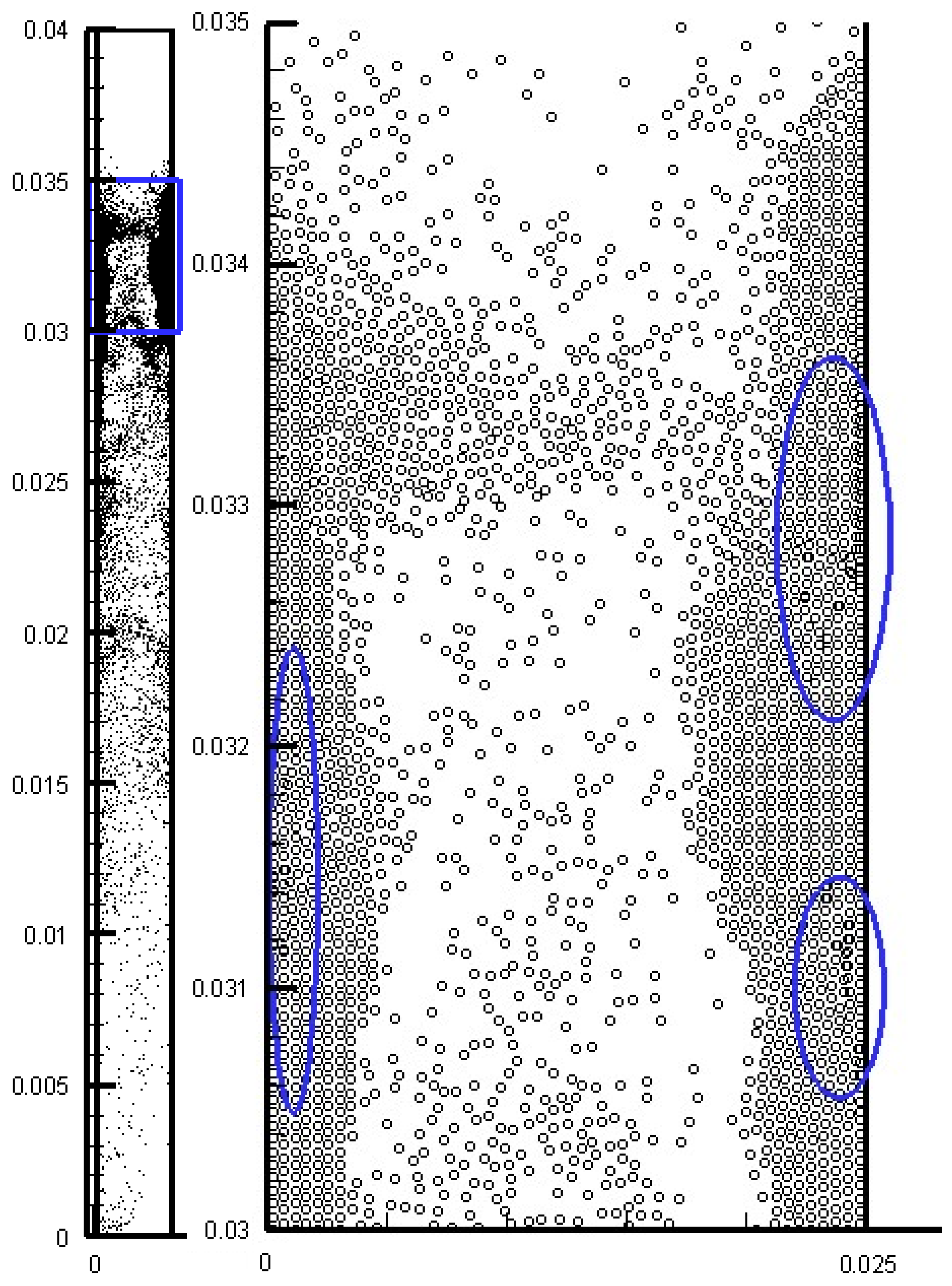
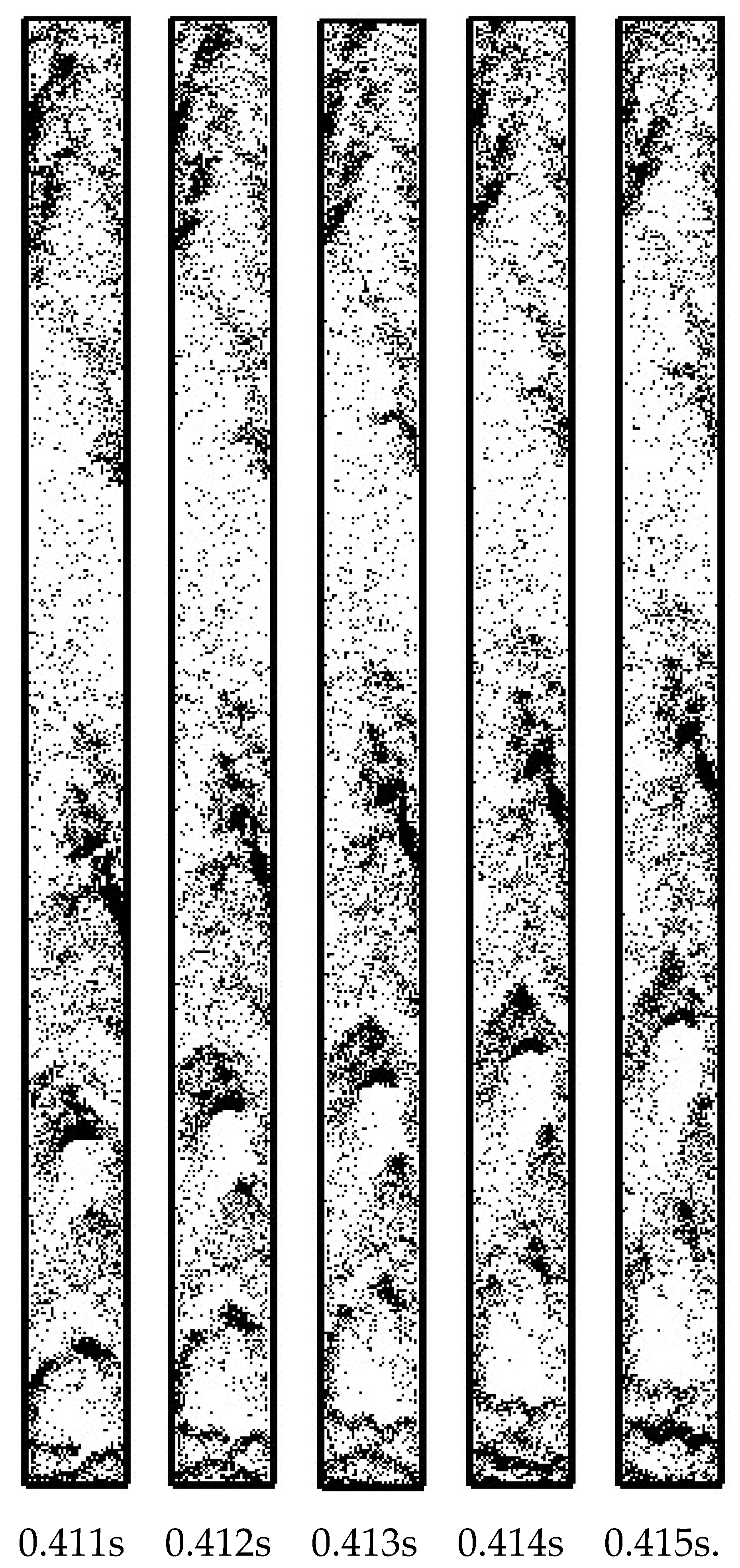
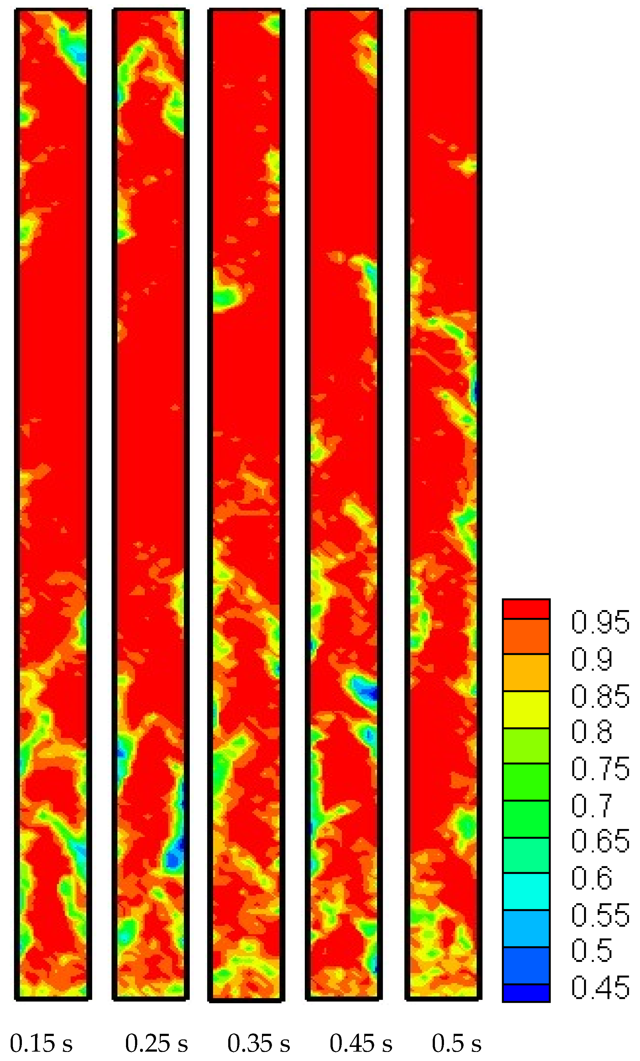
4.3. Fast Fluidization Structures

Figure 7 gives the voidage distributions at a moderate t r = 0.2 , corresponding to κ = 20 N/m. It can be observed that the gas–solid system had a distinct heterogeneous structure, both globally and locally. Particles formed clusters and dissolved dynamically. Clusters were observed falling along both sides of the wall, continuously competing against the up-flow of gas. At the macro scale, the flow structures exhibited dilute-top/dense-bottom and dilute-core/dense-wall characteristics. That large clusters were occasionally formed near the outlet was also noticed in Figure 7.
In their classic monograph on fluidization engineering [1], Jin et al. pointed out that particles exist mainly in the near-wall dense phase, during which they are fluidized and conveyed by high-speed gas velocity. This textbook conclusion supports the results of our simulations. As can be seen in Figure 7, the continuous phase was the dilute phase with diffuse particles inside it, with the mean voidage being close to one. On the other hand, in the discrete phase, clusters had particles gathered inside them, and the mean voidage grew closer to the minimal voidage. As can also be observed in Figure 7, particles tended to gather and stick to both sides of the wall to form dense clusters. This tendency determines the dilute-core/dense-wall heterogeneous structure in fast fluidized beds.
Figure 7 also shows that, in the near-inlet region, many small-sized bubbles rapidly formed and ruptured. The local flow exhibited a bubbling fluidized regime. On the other hand, in the bottom half of the riser, there were gas slugs and solid plugs of large sizes. The flow type exhibited a slugging fluidized regime. That the fluidization showed bubbling and slugging at the bottom of the fast fluidized bed was also reported by Jin et al. [1]. This tendency determines the dilute-top/dense-bottom heterogeneous structure in fast fluidized beds.
Figure 7 reflects that, occasionally, particles can accumulate to form large clusters in the bed’s outlet region. The boundaries between the dilute top and the dense bottom may be indistinct and not keep the same height due to flow instability. However, the clusters existing far away from the slugging region and near the bed outlet is not conducive to the global dilute-top/dense-bottom structure. This local structure was also reported by the simulations of Cabezas-Gómez et al. [30]. Anyway, it is an interesting phenomenon and needs to be further investigated.

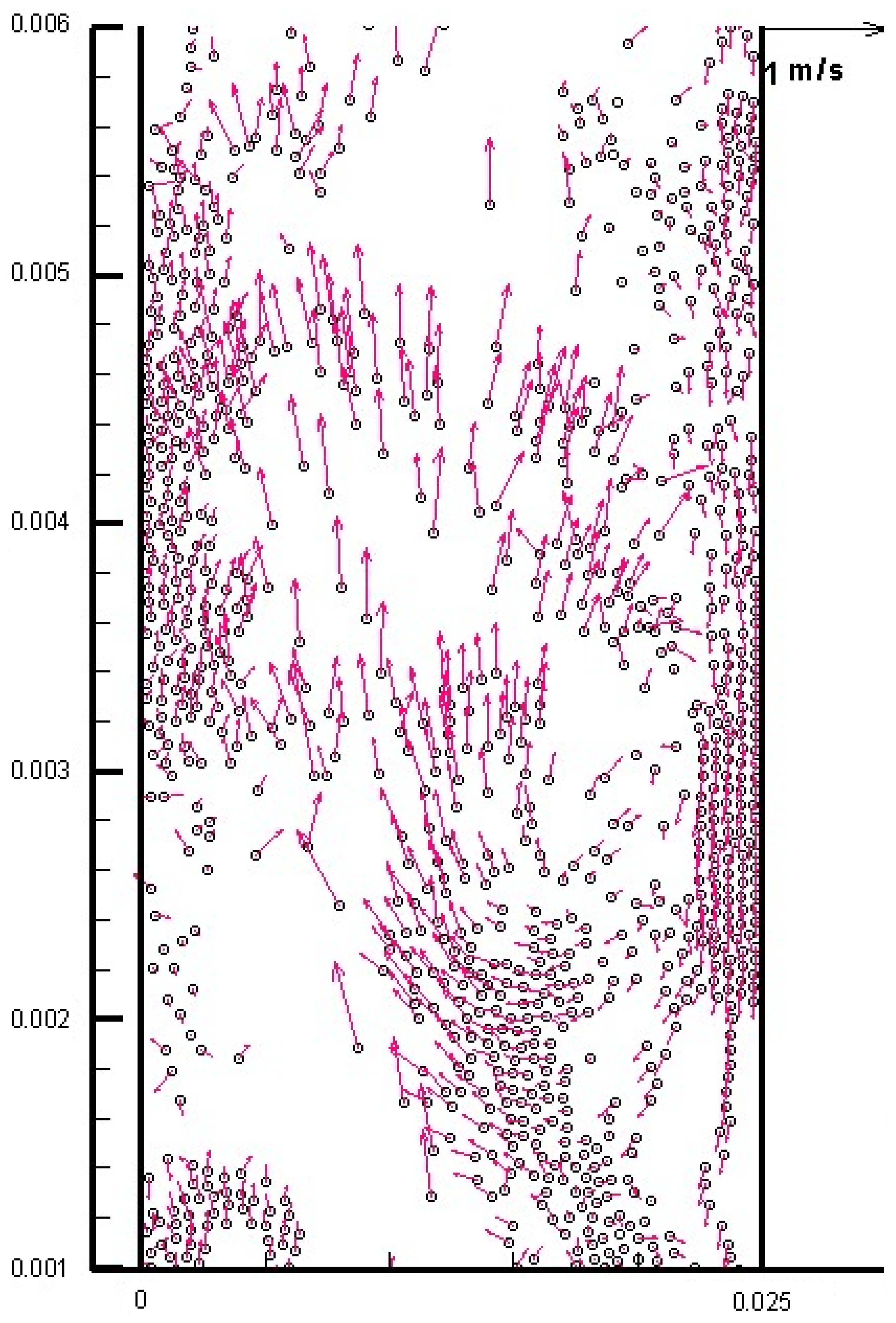
4.4. Solid Backmixing

Figure 8 gives the particle locations and velocities with moderate t r = 0.2 . It can be observed that the particles moved upward with high velocities in the core of the riser, and wandered with low velocities along the wall. There was obvious solid backmixing for those near-wall particles. Contrary to our previous study [23], the solid backmixing was not an occasional and minority behavior, but a frequent group behavior. That particles tended to surge up to the void region can also be noticed in the figure. This tendency also determines the relatively high horizontal velocity of particles.
Figure 7 and Figure 8 generally follow the well-known core-annulus model to describe the flow structures in fast fluidized beds, which was developed by Rhodes et al. [31]. Figure 7 shows a radial heterogeneous particle distribution with a dilute core and dense wall, while Figure 8 shows a radial heterogeneous distribution of particle velocity. In the core-annulus model, particles in the core of the bed always move upward with high velocities, while those in the annulus of the bed move downward. It is considered by some scholars that this core-annulus model reflects not only radial, but also axial, flow structures in fast fluidization. On one hand, in the radial direction, the flow field is distinctly divided into an upward-flow core region of the dilute phase and a downward flow annulus region of the dense phase. On the other hand, the core-annulus model describes the structure only in the bottom part of the riser; that is to say, in the top part of the riser, the flow structure tends to be relatively homogeneous. Therefore, the core-annulus model is sometimes thought of not as a one-dimensional model, but a one-and-a-half-dimensional model.
However, as an essentially time-averaged quantitative model, the core-annulus model predicted the mean values of the voidage and the flow velocity in the core and annulus regions. This coarse prediction was often not precise enough compared with experimental data. Figure 8 shows that the flow structure of the particle velocity did not strictly follow the core-annulus model. For example, there was no distinct boundary between the core region and the annulus region in Figure 8. The direction of the axial particle velocity could be downward even in the core of the bed, while it could be upward even close to the wall. Theoretically, anywhere in the radial direction, particles were able to instantaneously move upward or downward due to particle turbulence, backmixing, cluster formation and disruption. On the whole, the solid backmixing captured in Figure 8 generally followed the core-annulus model in the sense of qualitative tendencies.

4.5. Gas Backmixing

Figure 9 shows the gas velocity distribution with moderate t r = 0.2 . It can be observed that the gas velocity had a distinct heterogeneous structure, both globally and locally. There was also an obvious gas backmixing effect near the wall. As is also contrary to our previous study [23], the gas backmixing was not an occasional behavior, but a frequent one. In the macro sense, gas flowed upward in high velocities in the core region, and flowed slowly near the wall. In the local sense, gas velocity gradually changed in the core, while it changed in a disorderly manner, even in direction, near the wall. Thus, occasionally, there was a relatively high gas velocity, sometimes even a high horizontal gas velocity, near the wall.
Figure 9 also shows that there was a boundary (although not so distinct) between the upward (although not always) flow core region and downward (although not always) flow annulus region. On the whole, the gas backmixing captured in Figure 9 generally followed the core-annulus model in the sense of qualitative tendencies. The similarity of the velocity distributions shown in Figure 8 and Figure 9 may reflect the convergent traits between the gas and particle phases. That is, particles tended to be controlled upward by the gas phase, while gas tended to be controlled downward by the particles.

5. Conclusions

This study mainly discussed the suitable selection of stiffness constants and DEM time steps. To reflect their respective effects and complicated interaction, a so-called relative DEM time step was defined. The drag coefficient was correlated using the EMMS approach to reasonably calculate gas–solid interactions. Some conclusions are given as follows.
(1)
A micro-fast fluidized bed of Type-A FCC particles was studied by DEM simulations, which firstly proved that DEM can successfully model Type-A particles’ fast fluidization.
(2)
Only the use of a moderate relative time step can appropriately model the fast fluidization regime. Other relative time step choices lead to either calculation divergence or an untrue flow regime during fluidization.
(3)
Compared with traditional DEM, DEM employing EMMS-based drag force was able to greatly enlarge the suitable range of relative time steps in fast fluidization simulation with Type-A FCC particles. The suitable relative time step interval, i.e., the moderate relative time step interval, improved from [0.032, 0.1] to [0.018, 0.295].
(4)
The behaviors of particle and gas backmixing could be successfully captured, which was reported in other simulations and supported by data presented by experimental research.
(5)
The typical macro-flow structures of fast fluidization could also be successfully captured; they were axially dilute in the top and dense in the bottom, and radially dilute in the core and dense near the wall.

Author Contributions

Conceptualization, G.W.; methodology, G.W. and Y.L.; software, G.W.; validation, G.W. and M.I.; formal analysis, G.W.; investigation, G.W.; resources, G.W.; data curation, G.W.; writing—original draft preparation, G.W.; writing—review and editing, G.W.; visualization, G.W.; supervision, M.I. and Y.L.; and project administration, Y.L. All authors have read and agreed to the published version of the manuscript.

Funding

This research received funding supported by the National Natural Science Foundation of China (61962051), the Basic Research Program of Qinghai Province (2023-ZJ-736) and the Open Project of State Key Laboratory of Plateau Ecology and Agriculture, Qinghai University (2021-ZZ-02).

Institutional Review Board Statement

Not applicable.

Informed Consent Statement

Not applicable.

Data Availability Statement

The data presented in this study are available upon request from the corresponding author.

Conflicts of Interest

The authors declare no conflict of interest. The funders had no role in the design of the study; in the collection, analyses, or interpretation of data; in the writing of the manuscript; or in the decision to publish the results.

Nomenclature

Aparticle disk area, m2
Cdrag coefficient
dparticle diameter or distance between particle, m
Fforce on particle, N
ggravity acceleration, ms−2
Hbed height, m
HaHamaker constant, Nm
H0cut-off distance, m
Iinertia moment of the particle as spherical, kgm2
i, j, kparticle or grid indexes
Nparticle number
ppressure, Pa
ReReynolds number of particle
Ttorque, Nm
ttime, s
U0inlet gas velocity, ms−1
ugas velocity, ms−1
Vparticle volume, m3
vparticle velocity, ms−1
Greek letters
β momentum exchange coefficient, kgm−3s−1
ε porosity
κ stiffness constant, Nm−1
μ gas viscosity, Nsm−2
ρ density, kgm−3
τ viscous stress tensor, Pa
ω particle angular velocity, s−1
ξ restitution coefficient
Subscripts
2Dtwo-dimensional
3Dthree-dimensional
Ccontact
ccritical
ddrag
ggas
i, j, kparticle or grid indexes
mminimal
pparticle
rrelative
Vvan der Waals force type
wwall

References

  1. Jin, Y.; Zhu, J.X.; Wang, Z.W.; Yu, Z.Q. Fluidization Engineering Principles; Tsinghua University Press: Beijing, China, 2001. [Google Scholar]
  2. Tsuji, Y.; Kawaguchi, T.; Tanake, T. Discrete particle simulation of two-dimensional fluidized bed. Powder Technol. 1993, 77, 79–87. [Google Scholar] [CrossRef]
  3. Hoomans, B.P.B.; Kuipers, J.A.M.; Briels, W.J.; Van Swaaij, W.P.M. Discrete particle simulation of bubble and slug formation in a two-dimensional gas-fluidised bed: A hard-sphere approach. Chem. Eng. Sci. 1996, 51, 99–108. [Google Scholar] [CrossRef] [Green Version]
  4. Xu, B.H.; Yu, A.B. Numerical simulation of the gas-solid flow in a fluidized bed by combing discrete particle method with computational fluid dynamics. Chem. Eng. Sci. 1997, 52, 2785–2809. [Google Scholar] [CrossRef]
  5. Ouyang, J.; Li, J.H. Particle-motion-resolved discrete model for simulating gas-solid fluidization. Chem. Eng. Sci. 1999, 54, 2077–2083. [Google Scholar] [CrossRef]
  6. Geldart, D. Types of gas fluidization. Powder Technol. 1973, 7, 285–292. [Google Scholar]
  7. Ye, M.; van der Hoef, M.; Kuipers, J. 2004. A numerical study of fluidization behavior of Geldart A particles using a discrete particle model. Powder Technol. 2004, 139, 129–139. [Google Scholar] [CrossRef]
  8. Kobayashi, T.; Tanaka, T.; Kawaguchi, T.; Mukai, T.; Tsuji, Y. DEM analysis on flow patterns of Geldart’s group A particles in fluidized bed effect of adhesion and lubrication forces. J. Soc. Powder Technol. Jpn. 2006, 43, 737–745. [Google Scholar] [CrossRef]
  9. Di Renzo, A.; Di Maio, F.P. Homogeneous and bubbling fluidization regimes in DEM–CFD simulations: Hydrodynamic stability of gas and liquid fluidized beds. Chem. Eng. Sci. 2007, 62, 116–130. [Google Scholar] [CrossRef]
  10. Ye, M.; van der Hoef, M.A.; Kuipers, J. The effects of particle and gas properties on the fluidization of Geldart A particles. Chem. Engi. Sci. 2005, 60, 4567–4580. [Google Scholar] [CrossRef]
  11. Wang, J.W.; Van der Hoef, M.; Kuipers, J. CFD study of the minimum bubbling velocity of Geldart A particles in gas-fluidized beds. Chem. Eng. Sci. 2010, 65, 3772–3785. [Google Scholar] [CrossRef]
  12. Hou, Q.; Zhou, Z.; Yu, A. Micromechanical modeling and analysis of different flow regimes in gas fluidization. Chem. Eng. Sci. 2010, 84, 449–468. [Google Scholar]
  13. Weber, M.W.; Hrenya, C.M. Square-well model for cohesion in fluidized beds. Chem. Eng. Sci. 2006, 61, 4511–4527. [Google Scholar] [CrossRef]
  14. Yang, F.; Thornton, C.; Seville, J. Effect of surface energy on the transition from fixed to bubbling gas-fluidised beds. Chem. Eng. Sci. 2013, 90, 119–129. [Google Scholar] [CrossRef] [Green Version]
  15. Galvin, J.E.; Benyahia, S. The effect of cohesive forces on the fluidization of aeratable powders. AIChE J. 2014, 60, 473–484. [Google Scholar] [CrossRef]
  16. Liu, P.; LaMarche, C.Q.; Kellogg, K.M.; Hrenya, C.M. Fine-particle defluidization: Interaction between cohesion, Young’s modulus and static bed height. Chem. Eng. Sci. 2016, 145, 266–278. [Google Scholar] [CrossRef] [Green Version]
  17. Pandit, J.K.; Wang, X.S.; Rhodes, M.J. Study of Geldart’s Group A behaviour using the discrete element method simulation. Powder Technol. 2005, 160, 7–14. [Google Scholar] [CrossRef]
  18. Pandit, J.K.; Wang, X.S.; Rhodes, M.J. On Geldart Group A behaviour in fluidized beds with and without cohesive interparticle forces: A DEM study. Powder Technol. 2006, 164, 130–138. [Google Scholar] [CrossRef]
  19. Wang, J.W.; Van der Hoef, M.; Kuipers, J. Why the two-fluid model fails to predict the bed expansion characteristics of Geldart A particles in gas-fluidized beds: A tentative answer. Chem. Eng. Sci. 2009, 64, 622–625. [Google Scholar] [CrossRef]
  20. Kobayashi, T.; Tanaka, T.; Shimada, N.; Kawaguchi, T. DEM-CFD analysis of fluidization behavior of Geldart Group A particles using a dynamic adhesion force model. Powder Technol. 2013, 248, 143–152. [Google Scholar] [CrossRef]
  21. Li, T.; Rabha, S.; Verma, V.; Dietiker, J.F.; Xu, Y.; Lu, L.; Rogers, W.; Gopalan, B.; Breault, G.; Tucker, J.; et al. Experimental study and discrete element method simulation of Geldart Group A particles in a small-scale fluidized bed. Adv. Powder Technol. 2017, 28, 2961–2973. [Google Scholar] [CrossRef]
  22. Li, S.; Zhao, P.; Xu, J.; Zhang, L.; Wang, J. Direct comparison of CFD-DEM simulation and experimental measurement of Geldart A particles in a micro-fluidized bed. Chem. Eng. Sci. 2021, 64, 622–625. [Google Scholar] [CrossRef]
  23. Wu, G.R.; Li, Y.G. DPM simulations of A-Type FCC particles’ fast fluidization by use of structure-dependent nonlinear drag force. Processes 2021, 9, 1574. [Google Scholar] [CrossRef]
  24. Wu, G.R.; Zuo, Z.F.; Li, Y.G. Selection of relative DEM time step for modelling fast fluidized bed of A-Type FCC particles. Symmetry 2023, 15, 488. [Google Scholar] [CrossRef]
  25. Patankar, T.V. Numerical Heat Transfer and Fluid Flow; Hemisphere Publishing Corporation: New York, NY, USA, 1980. [Google Scholar]
  26. Wen, C.Y.; Yu, Y.H. Mechanics of fluidization. Chem. Eng. Progr. Symp. Ser. 1966, 62, 100–111. [Google Scholar]
  27. Wu, G.R.; Ouyang, J.; Li, Q. Revised drag calculation method for coarse grid Lagrangian-Eulerian simulation of gas-solid bubbling fluidized bed. Powder Technol. 2013, 235, 959–967. [Google Scholar] [CrossRef]
  28. Yang, N.; Wang, W.; Ge, W.; Li, J.H. CFD simulation of concurrent-up gas-fluid flow in circulating fluidized beds with structure-dependent drag coefficient. Chem. Eng. J. 2003, 96, 71–80. [Google Scholar] [CrossRef]
  29. Yuu, S.; Abe, T.; Saitoh, T.; Umek, T. Three-dimensional numerical simulation of the motion of particles discharging from a rectangular hopper using distinct element method and comparison with experimental data (effects of time steps and material properties). Adv. Powder Technol. 1995, 6, 259–269. [Google Scholar] [CrossRef]
  30. Cabezas-Gómez, L.; de Silva, R.C.; Navarro, H.A.; Milioli, F.E. Cluster identification and characterization in the riser of a circulating fluidized bed from numerical simulation results. Appl. Math. Model. 2008, 32, 327–340. [Google Scholar] [CrossRef] [Green Version]
  31. Rhodes, M.J. Modelling the flow structure of upward-flowing gas-solid suspensions. Powder Technol. 1990, 60, 27–38. [Google Scholar] [CrossRef]
Figure 1. Particle locations at 0.079 s, with over-large t r = 0.45 .
Processes 11 01155 g001
Figure 2. Particle locations at 0.123 s, with large t r = 0.31 .
Processes 11 01155 g002
Figure 3. Particle locations with large t r = 0.31 .
Processes 11 01155 g003
Figure 4. Particle locations at 0.018 s, with large t r = 0.295 .
Processes 11 01155 g004
Figure 5. Particle locations at 0.381 s, with moderate t r = 0.018 .
Processes 11 01155 g005
Figure 6. Particle locations at 0.074 s with over-low t r = 0.016 .
Processes 11 01155 g006
Figure 7. Voidage with moderate t r = 0.2 .
Processes 11 01155 g007
Figure 8. Particle locations and velocity with moderate t r = 0.2 .
Processes 11 01155 g008
Figure 9. Gas velocity with moderate t r = 0.2 .
Processes 11 01155 g009
Table 1. Fixed parameters of solid and gas phases.
Solid PhaseGas Phase
Particle density ρp = 930 kg·m−3Gas viscosity μg = 1.7 × 10⁻⁵ N·s·m−2
Particle diameter dp = 54 μmGas density ρg = 1.28 kg·m−3
Minimal fluidization voidage εmf = 0.45Inlet gas velocity U0 = 1.7 m·s−1
Particle number N = 8230CFD time step Δtg = 2 × 10⁻⁶ s
Friction coefficient μ = 0.3
Restitution coefficient ξ = 0.9
DEM time step Δtp = 2.5 × 10⁻⁷ s
Table 2. Variable parameters.
Stiffness Constant κ Relative   DEM   Time   Step   t r Rank   of   t r
100 N·m−10.45Over-large
45 N·m−10.31Large
40 N·m−10.295Moderate
20 N·m−10.2Moderate
0.15 N·m−10.018Moderate
0.13 N·m−10.016Over-low
Disclaimer/Publisher’s Note: The statements, opinions and data contained in all publications are solely those of the individual author(s) and contributor(s) and not of MDPI and/or the editor(s). MDPI and/or the editor(s) disclaim responsibility for any injury to people or property resulting from any ideas, methods, instructions or products referred to in the content.

