
Control Mechanism and Support Technology of Deep Roadway Intersection with Large Cross-Section: Case Study

Abstract
:1. Introduction
2. Project Background
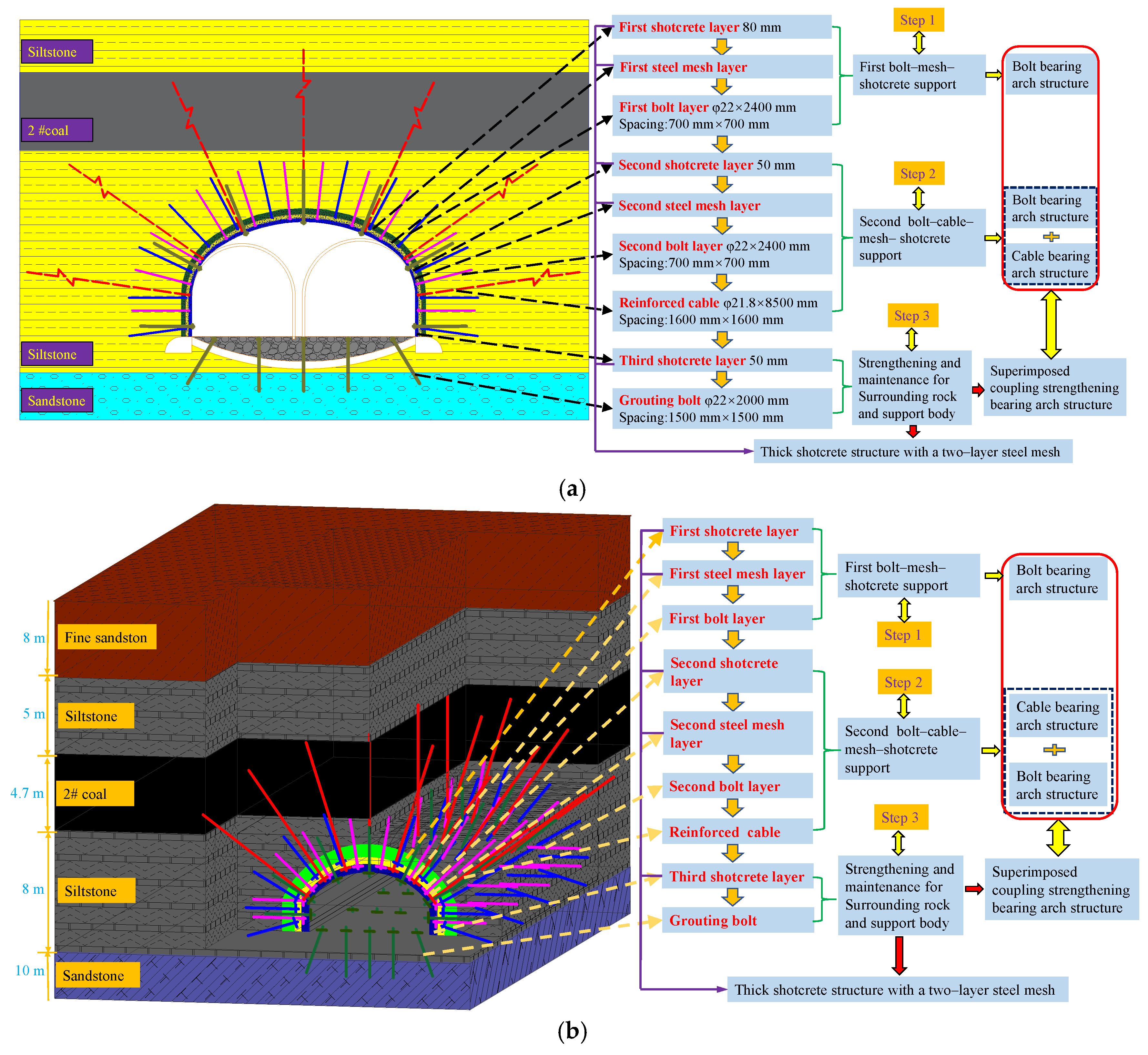
2.1. Project Overview
2.2. Primary Support Scheme and Strata Behavior Characteristics
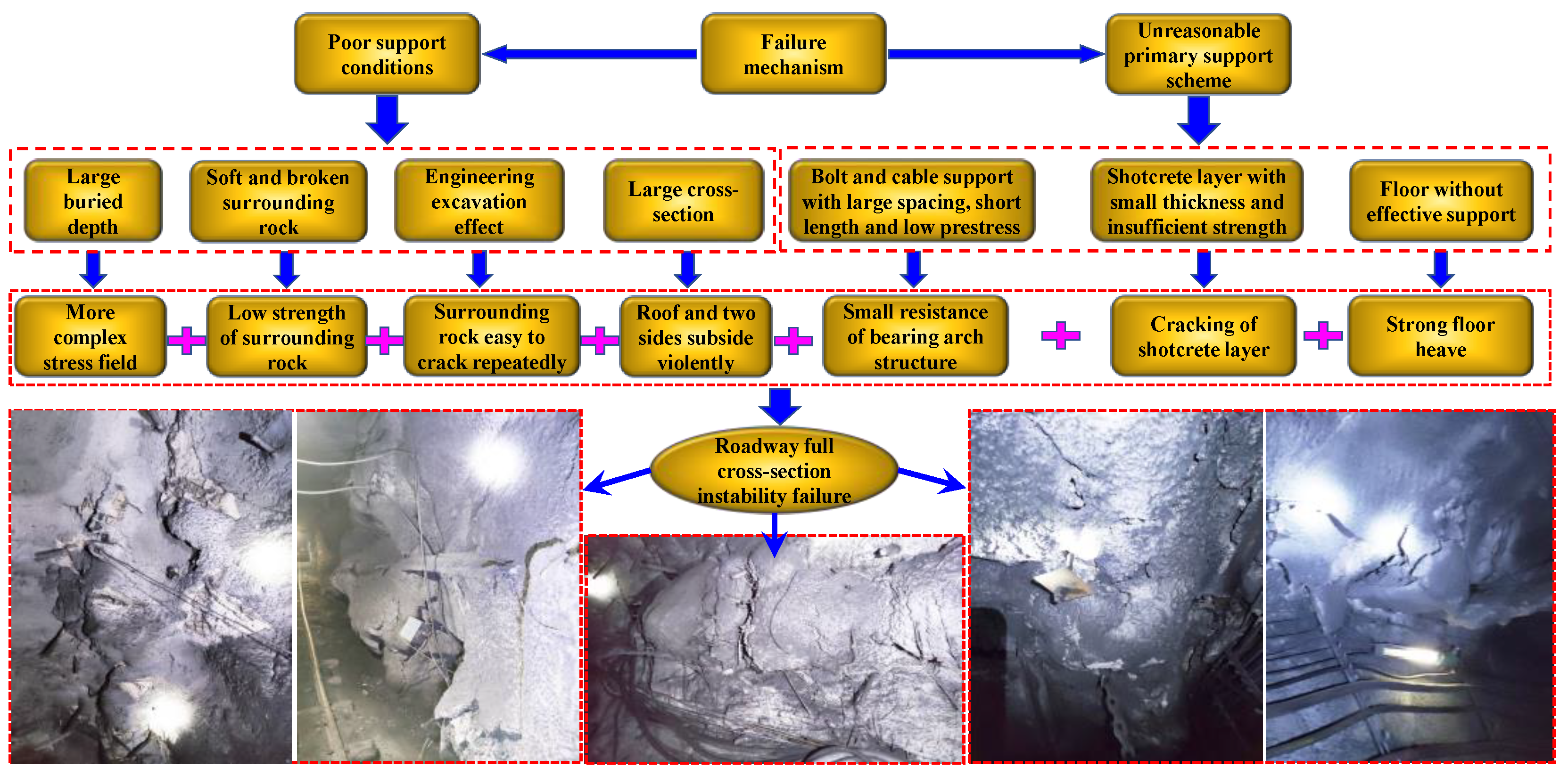
2.3. Failure Mechanism Analysis of Roadway Intersection
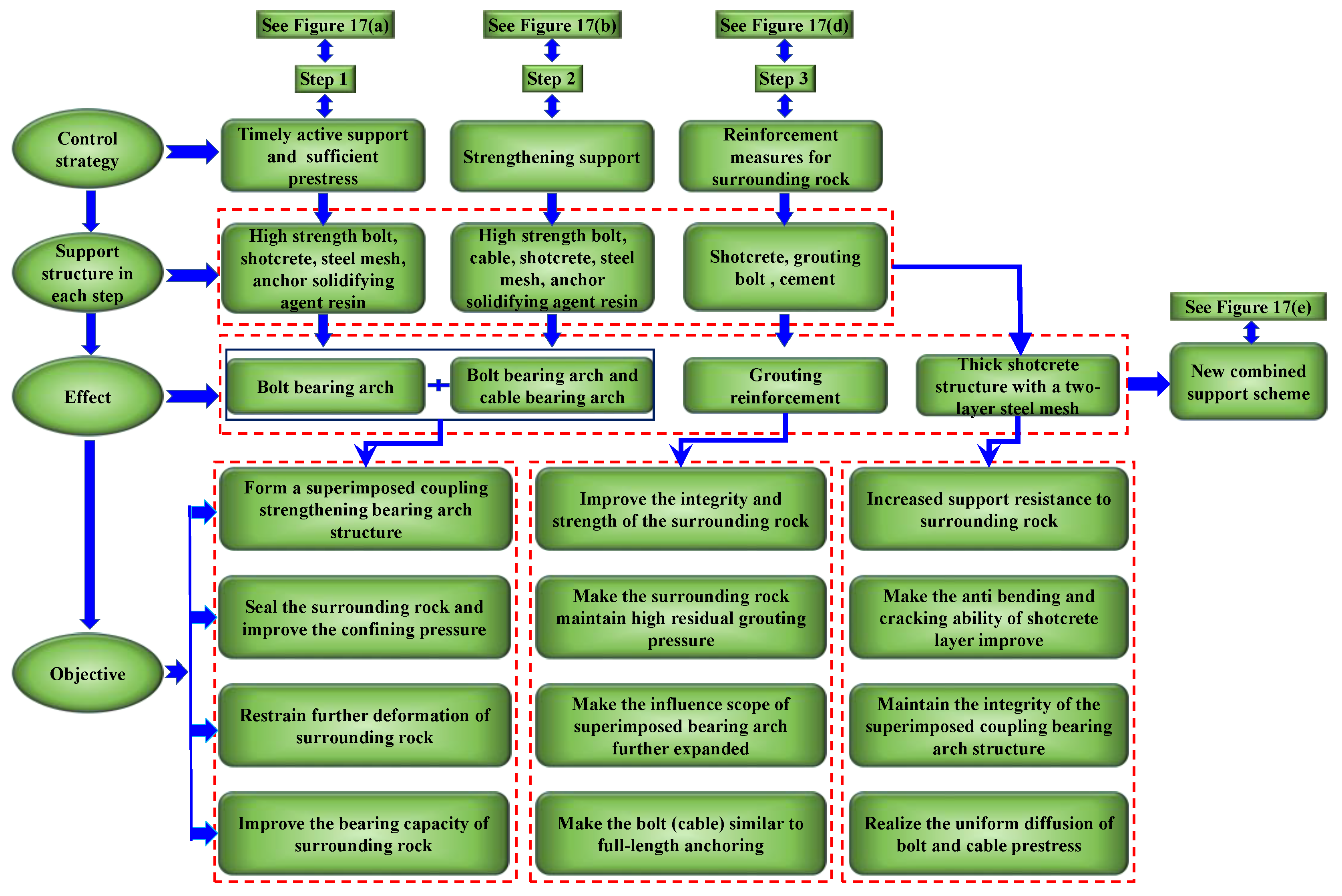
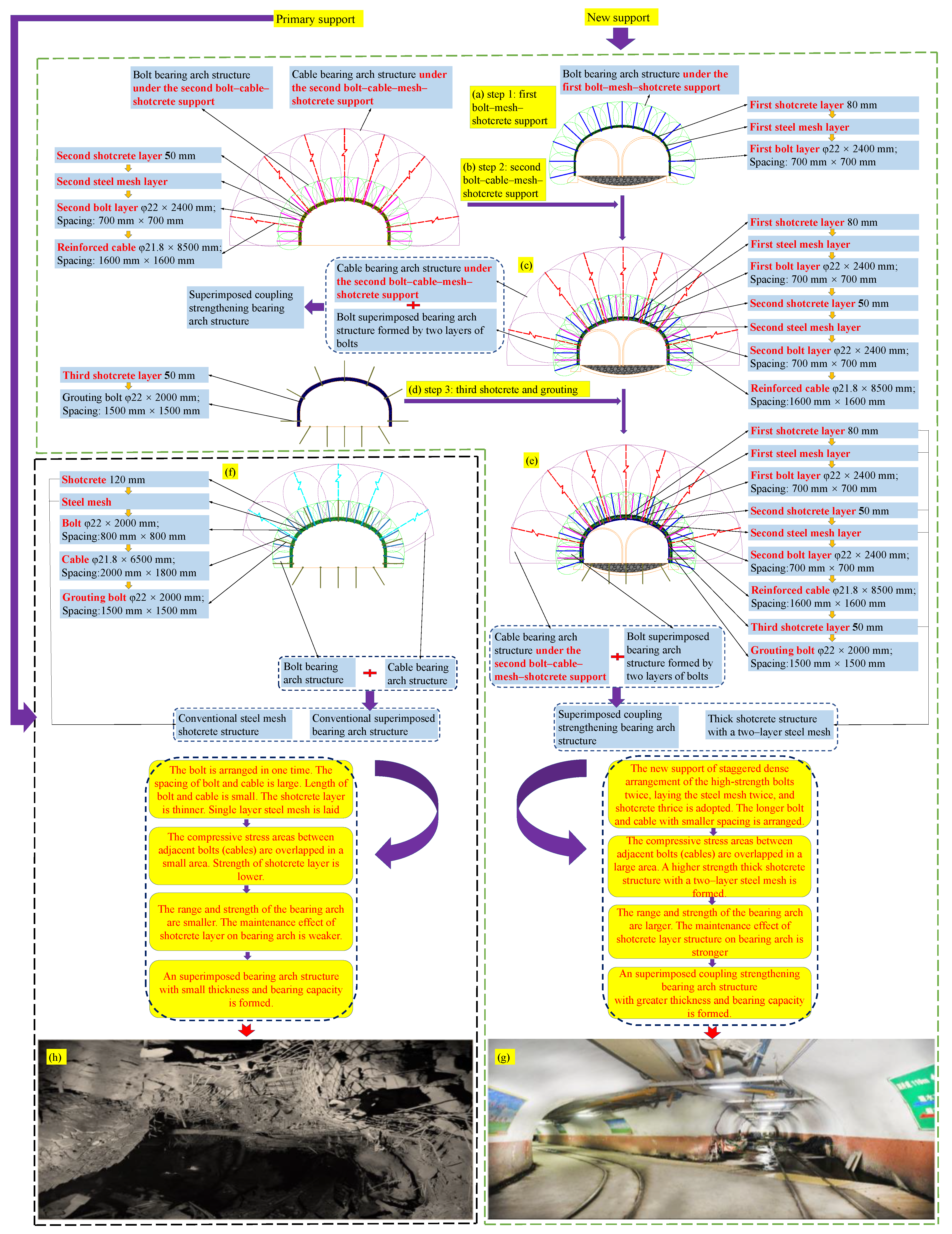
3. New Combined Support Technology
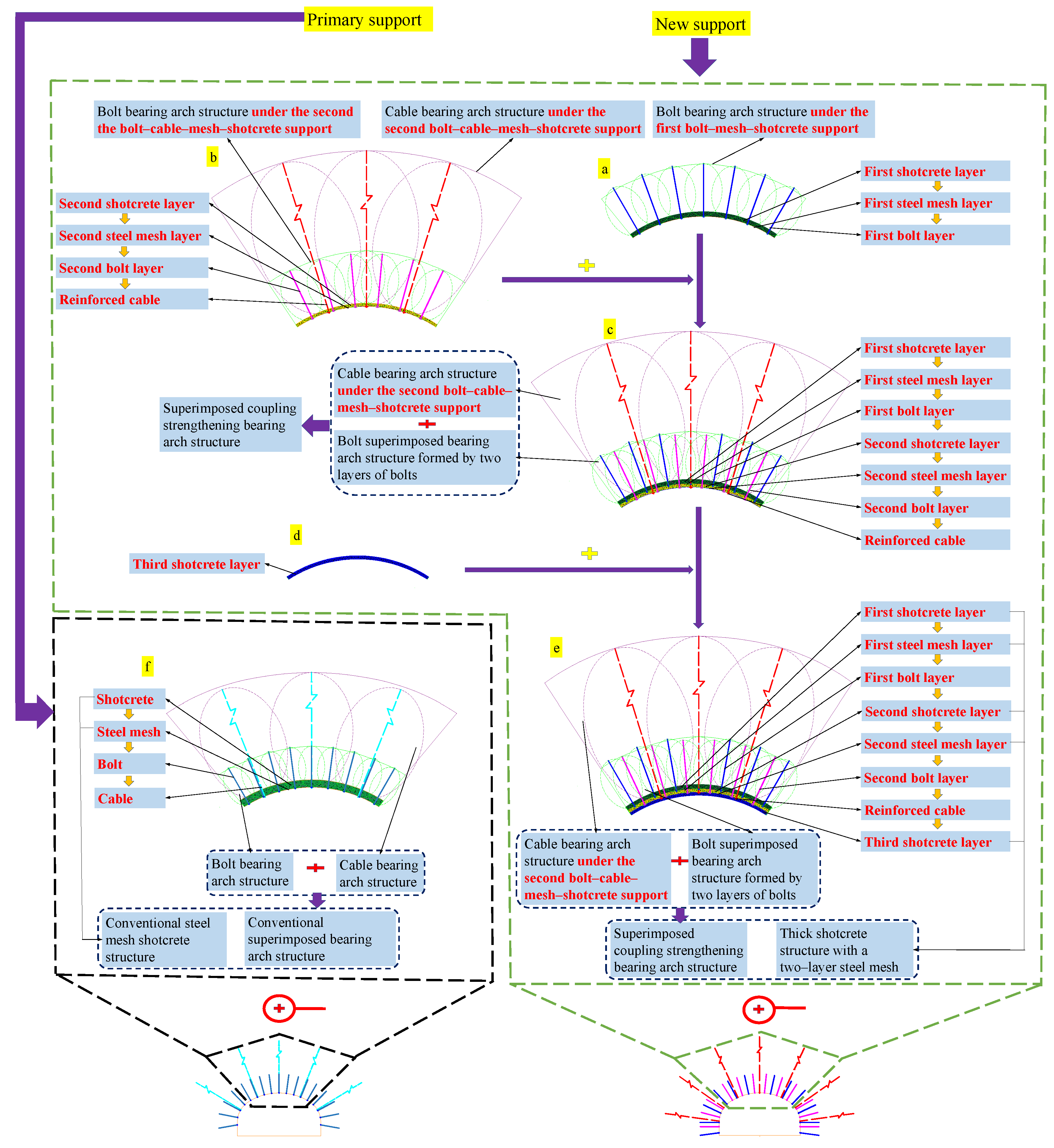
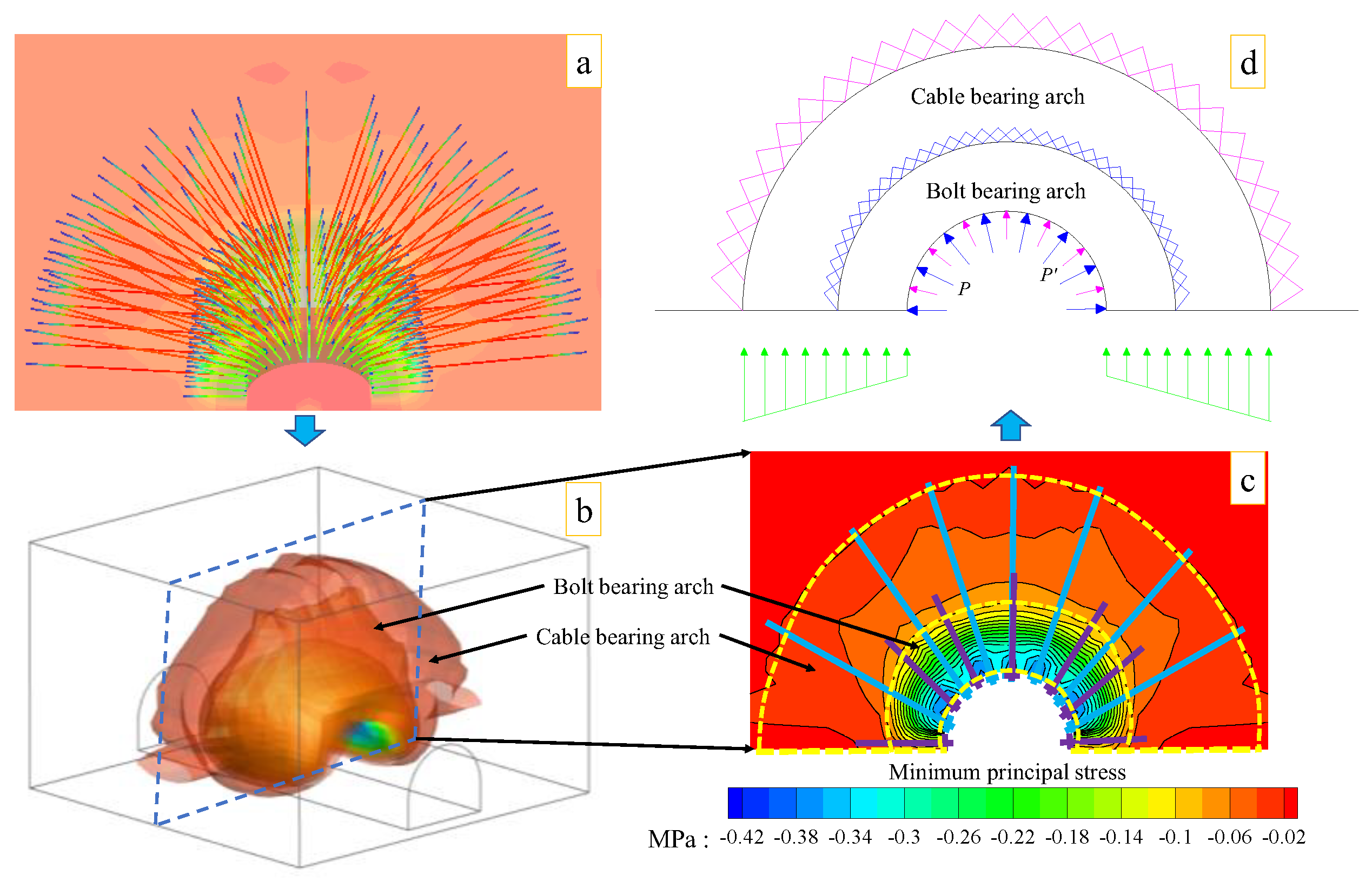
3.1. Superimposed Coupling Strengthening Bearing Arch Support Technology and Mechanism
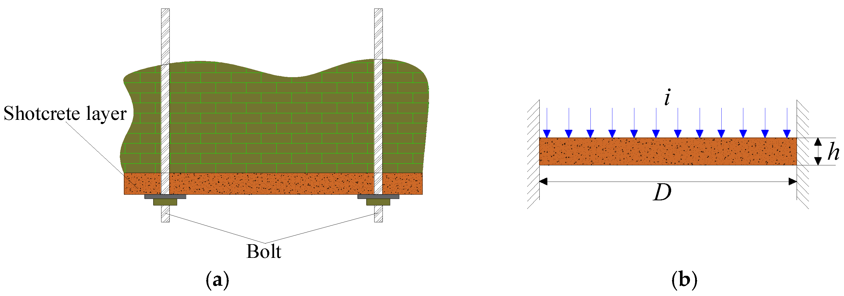
3.2. Technology and Mechanism of Grouting Reinforcement for the Full Cross-Section of Surrounding Rock
4. Numerical Analysis for Primary Support and New Support
4.1. Parameters of Primary and New Supports
4.2. Numerical Model Generation
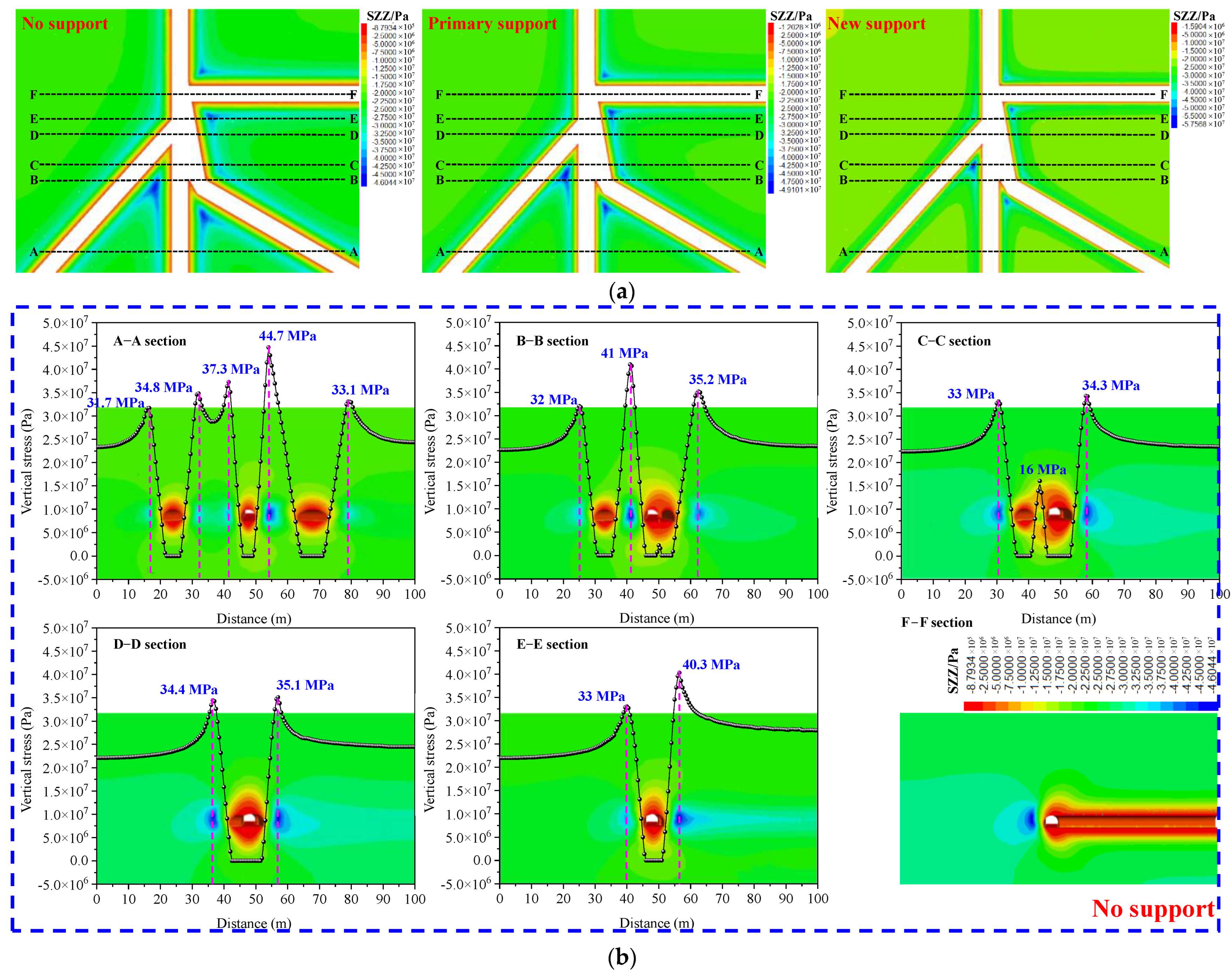
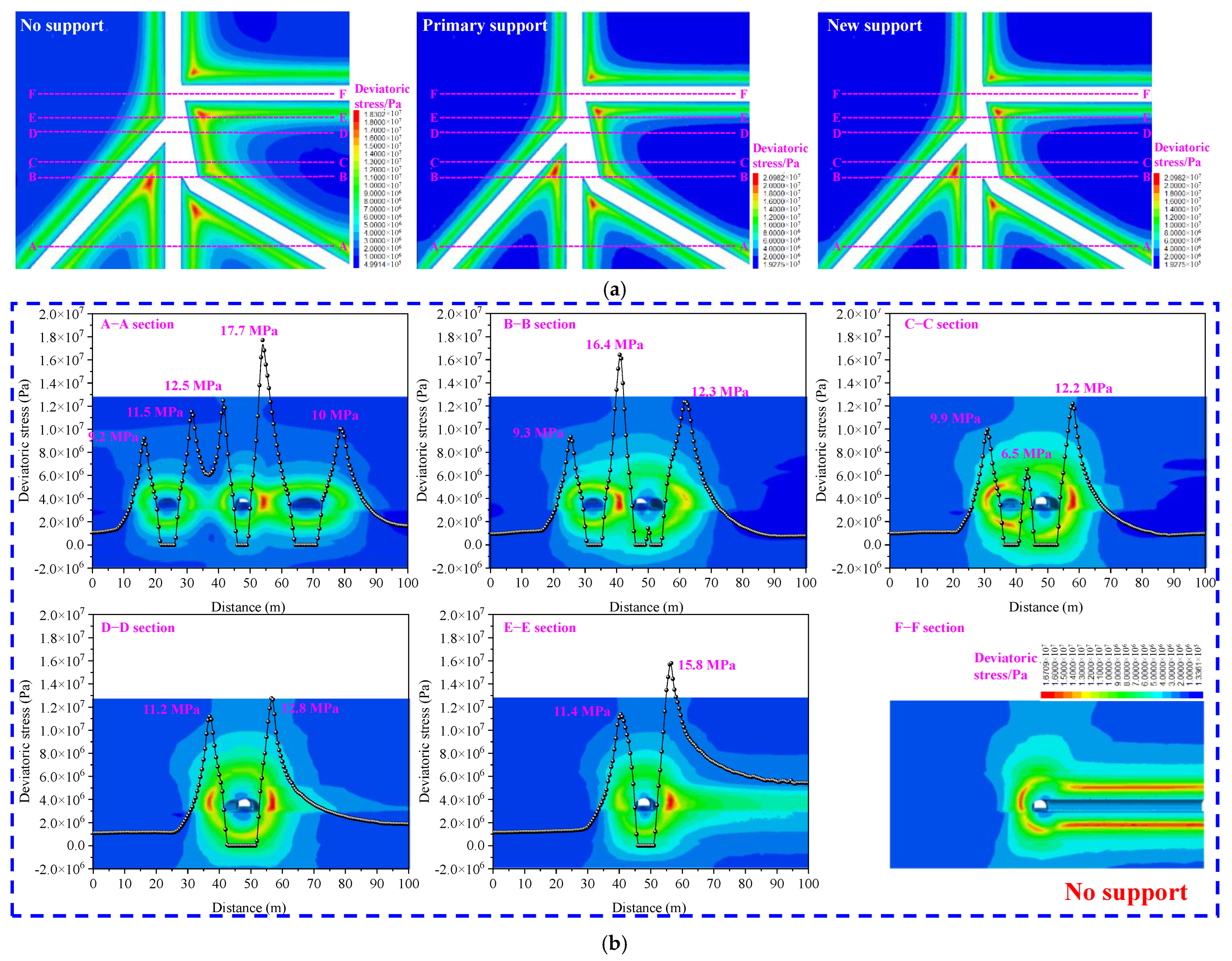
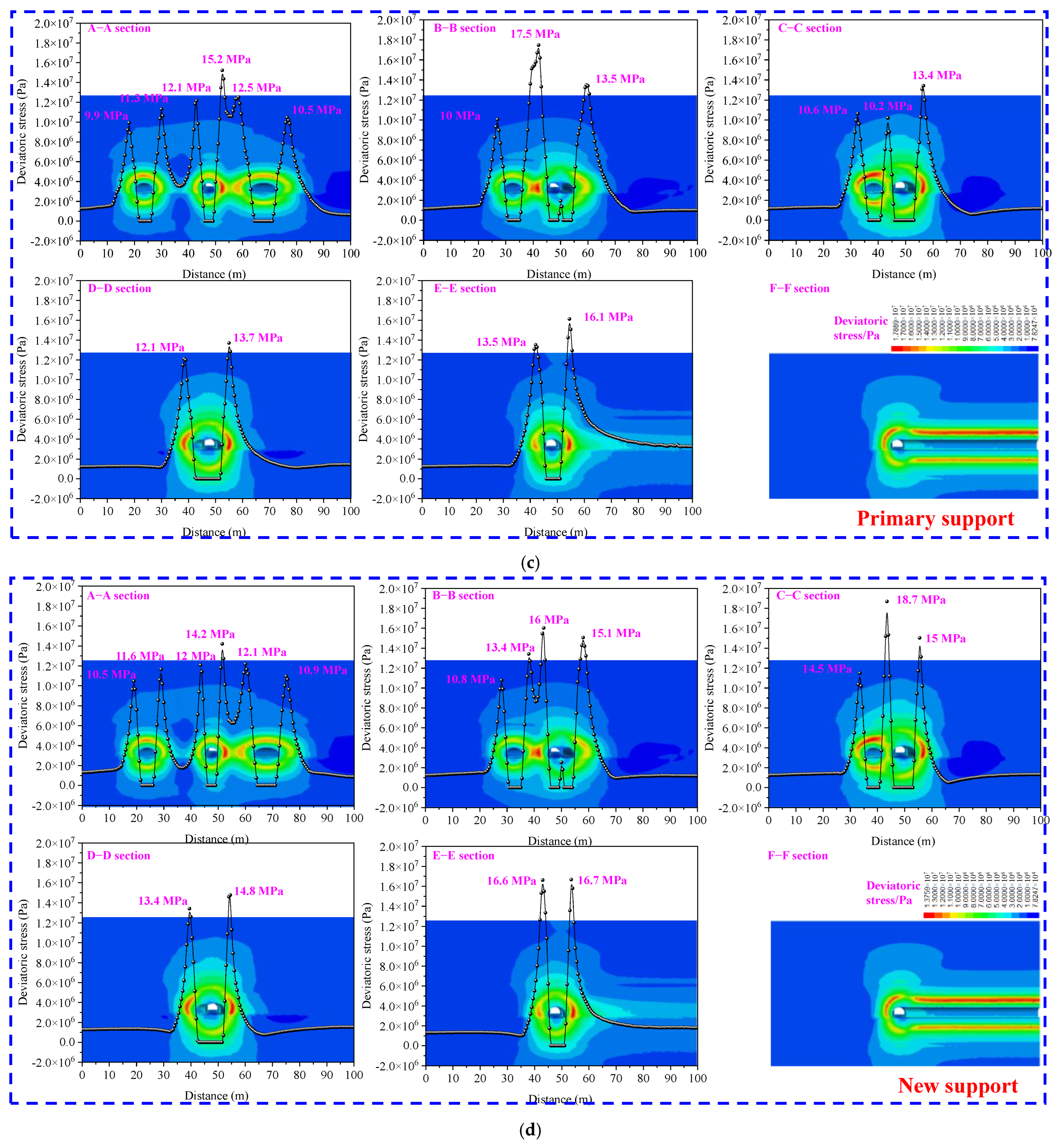
4.3. Numerical Model Results Analysis
4.3.1. Vertical Stress Analysis
4.3.2. Deviatoric Stress Analysis
4.3.3. Plastic Zone Analysis
5. Industrial Test
5.1. Technological Process for New Combined Support Technology
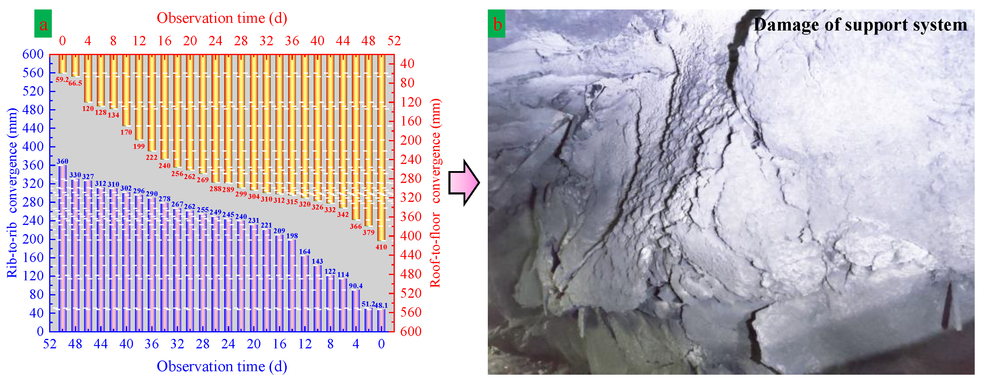
5.2. Strata Control Observation at Test Roadway Intersection
- (1)
- Surface convergence
- (2)
- Borehole drilling results of roadway roof and side
6. Conclusions
- (1)
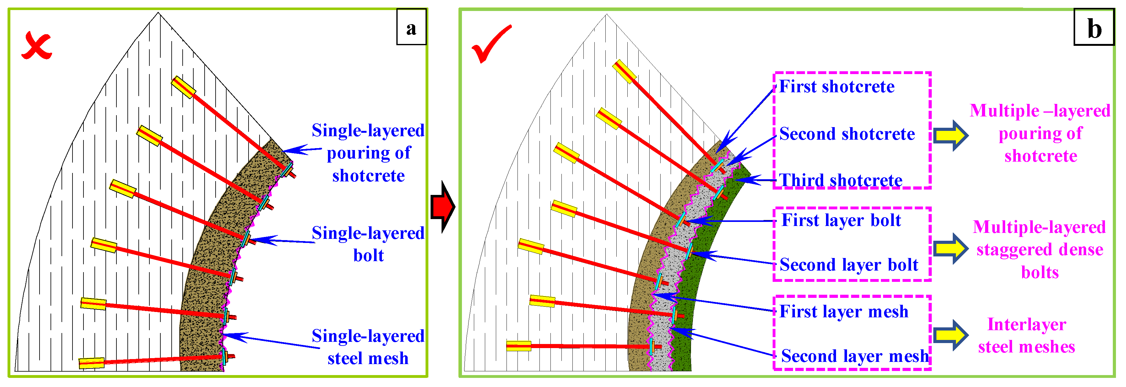
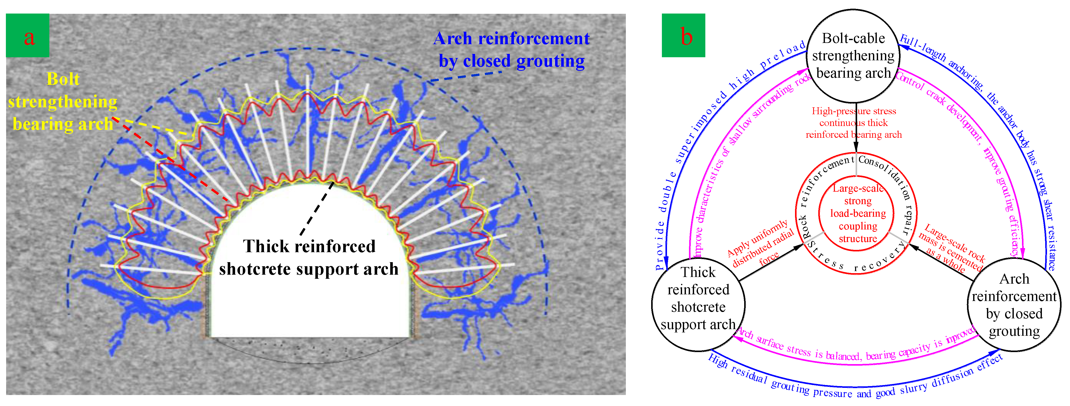
- The staggered arrangement of the two layers of high-strength bolts forms a thick strengthening bearing arch, improving the stress state of the shallow surrounding rock and weakening the borehole disturbance. The multiple–layered pouring of shotcrete, multiple-layered staggered dense bolts, and interlayer steel meshes form a new type of high-strength bending and crack-resistant reinforced concrete supporting arch structure with built-in multi-layer steel meshes, providing radial overall support stress distribution for the surrounding rock. Grouting is carried out under the conditions of strong sealing of the surrounding rock with a thick reinforced concrete support arch, which further expands the reinforcement scope of the surrounding rock.
- (2)
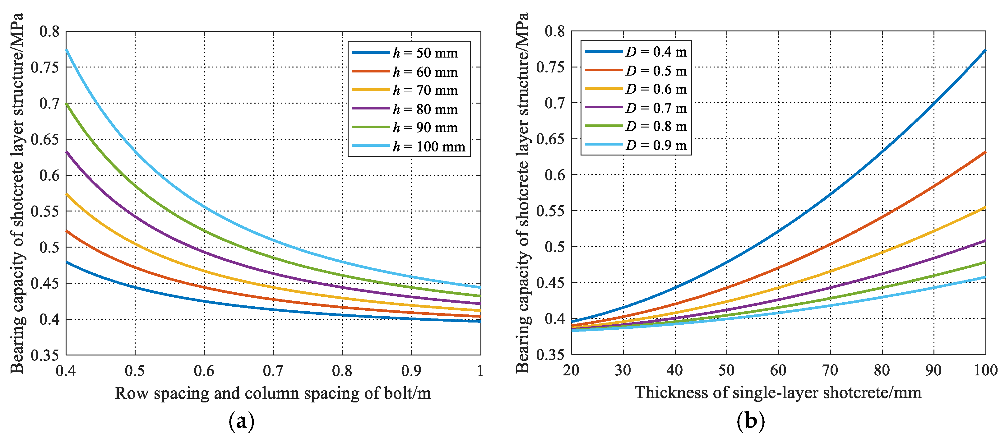
- By establishing the mechanical model of the superimposed coupling strengthening bearing arch, the relationship between its bearing capacity and the bolt (cable) spacing and support resistance is obtained. By establishing the shotcrete-layer structure mechanical model, the relationship between its bearing capacity and the bolt (cable) spacing and the single-layer shotcrete thickness is obtained. Analysis of the above two equations shows that when the bolt spacing was between 0.4 m and 0.7 m, it was more conducive to the stability of the surrounding rock. With the increase in the single-layer shotcrete thickness (from 50 mm to 100 mm), the bearing capacity of the shotcrete structure increased rapidly in the form of a power function.
- (3)
- The numerical simulation results show that, after the multi-level bolt–shotcrete support structure was adopted, the overall stress level of the shallow surrounding rock at the roadway intersection was improved, the bearing capacity of the shallow rock mass was improved, the ring peak zone of the deviatoric stress of the surrounding rock at the roadway intersection was largely transferred to the shallow part, and the plastic zone of the surrounding rock of the roadway was reduced by 43.3~52.3% compared to that of the conventional bolt–shotcrete support.
- (4)
- After the new combined support technology process was adopted, the roadway intersection convergences tended to be stable after 26 days, the final roof-to-floor and rib-to-rib convergences of the roadway intersections were 114 mm and 91 mm, respectively. Moreover, the maximum roof-to-floor and rib-to-rib convergence rates of the roadway intersection were 12.3 mm/d and 7.9 mm/d, respectively. These results prove that the new combined support technology could achieve long-term stability of the surrounding rock of the deep roadway, avoid frequent expansions and renovations of the roadway, and also save a lot of maintenance costs, ensuring the normal production of the working face.
7. Discussion
Author Contributions
Funding
Institutional Review Board Statement
Informed Consent Statement
Data Availability Statement
Acknowledgments
Conflicts of Interest
References
- Wang, Q.W.; Feng, H.; Tang, P.; Peng, Y.T.; Li, C.A.; Jiang, L.S.; Mitri, H.S. Influence of yield pillar width on coal mine roadway stability in western china: A case study. Processes 2022, 10, 251. [Google Scholar] [CrossRef]
- Ma, C.Q.; Wang, P.; Jiang, L.S.; Wang, C.S. Deformation and control countermeasure of surrounding rocks for water-dripping roadway below a contiguous seam goaf. Processes 2018, 6, 77. [Google Scholar] [CrossRef]
- Chang, J.C.; He, K.; Pang, D.D.; Li, D.; Li, C.M.; Su, B.J. Influence of anchorage length and pretension on the working resistance of bolt based on its tensile characteristics. Int. J. Coal Sci. Technol. 2021, 8, 1384–1399. [Google Scholar] [CrossRef]
- Chen, J.H.; Zhao, H.B.; He, F.L.; Zhang, J.W.; Tao, K.M. Studying the performance of fully encapsulated bolts with modified structural elements. Int. J. Coal Sci. Technol. 2021, 8, 64–76. [Google Scholar] [CrossRef]
- Liu, P.Z.; Gao, L.; Zhang, P.D.; Wu, G.Y.; Wang, C.; Ma, Z.Q.; Kong, D.Z.; Kang, X.T.; Han, S. A case study on surrounding rock deformation control technology of gob-side coal-rock roadway in inclined coal seam of a mine in Guizhou, China. Processes 2022, 10, 863. [Google Scholar] [CrossRef]
- Xie, S.R.; Jiang, Z.S.; Chen, D.D.; Wang, E.; Lv, F. A new pressure relief technology by internal hole-making to protect roadway in two sides of deep coal roadway: A case study. Rock Mech. Rock Eng. 2023, 56, 1537–1561. [Google Scholar] [CrossRef]
- Chen, D.D.; Guo, F.F.; Li, Z.J.; Ma, X.; Xie, S.R.; Wu, Y.Y.; Wang, Z.Q. Study on the influence and control of stress direction deflection and partial-stress boosting of main roadways surrounding rock and under the influence of multi-seam mining. Energies 2022, 15, 8257. [Google Scholar] [CrossRef]
- Fu, Q.; Yang, K.; He, X.; Liu, Q.J.; Wei, Z.; Wang, Y. Destabilization mechanism and stability control of the surrounding rock in stope mining roadways below remaining coal pillars: A case study in buertai coal mine. Processes 2022, 10, 2192. [Google Scholar] [CrossRef]
- Li, G.C.; Sun, Y.T.; Zhang, J.F.; Zhang, Q.J.; Sun, C.L.; Zhang, S.H.; Bi, R.Y. Experiment and application of coalcrete on roadway stability: A comparative analysis. Adv. Mater. Sci. Eng. 2020, 2020, 6813095. [Google Scholar] [CrossRef]
- Ma, Q.; Zhang, Y.D.; Zhang, X.R.; Li, Z.X.; Song, G.Y.; Cheng, J.Y.; Gao, K.D. The failure law and control technology of large-section roadways in gently inclined soft coal seams. Processes 2022, 10, 1993. [Google Scholar] [CrossRef]
- Xie, S.R.; Wang, E.; Chen, D.D.; Jiang, Z.S.; Li, H.; Liu, R.P. Collaborative control technology of external anchor-internal unloading ofsurrounding rock in deep large-section coal roadway under strong mining influence. J. China Coal Soc. 2022, 47, 1946–1957. [Google Scholar]
- Xie, S.R.; Wu, Y.Y.; Chen, D.D.; Liu, R.P.; Han, X.T.; Ye, Q.C. Failure analysis and control technology of intersections of large-scale variable cross-section roadways in deep soft rock. Int. J. Coal Sci. Technol. 2022, 9, 19. [Google Scholar] [CrossRef]
- Chen, D.D.; Wu, Y.Y.; Xie, S.R.; GUo, F.F.; He, F.L.; Liu, R.P. Reasonable location of stopping line in close-distance underlying coal seam and partition support of large cross-section roadway. Int. J. Coal Sci. Technol. 2022, 9, 55. [Google Scholar] [CrossRef]
- Yu, W.J.; Li, K. Deformation mechanism and control technology of surrounding rock in the deep-buried large-span chamber. Geofluids 2020, 2020, 8881319. [Google Scholar] [CrossRef]
- Xie, S.R.; Jiang, Z.S.; Chen, D.D.; Wang, E. Study on zonal cooperative control technology of surrounding rock of super large section soft rock chamber group connected by deep vertical shaft. Adv. Civ. Eng. 2022, 2022, 4220998. [Google Scholar] [CrossRef]
- Shi, S.; Miao, Y.C.; Wu, H.K.; Xu, Z.P.; Liu, C.W. The stress evolution of adjacent working faces passing through an abandoned roadway and the damage depth of the floor. Energies 2022, 15, 5824. [Google Scholar] [CrossRef]
- Qin, B.B.; He, F.L.; Zhang, X.B.; Xu, X.H.; Wang, W.; Li, L.; Dou, C. Stability and control of retracement channels in thin seam working faces with soft roof. Shock Vib. 2021, 2021, 8667471. [Google Scholar] [CrossRef]
- Xia, Z.; Yao, Q.L.; Meng, G.S.; Xu, Q.; Tang, C.J.; Zhu, L.; Wang, W.N.; Shen, Q. Numerical study of stability of mining roadways with 6.0-m section coal pillars under influence of repeated mining. Int. J. Rock Mech. Min. Sci. 2021, 138, 104641. [Google Scholar] [CrossRef]
- Yu, Y.; Wang, X.Y.; Bai, J.B.; Zhang, L.Y.; Xia, H.C. Deformation mechanism and stability control of roadway surrounding rock with compound roof: Research and application. Energies 2020, 13, 1350. [Google Scholar] [CrossRef]
- Hu, C.J.; Han, C.L.; Wang, L.X.; Zhao, B.F.; Yang, H.Q. Cooperative control mechanism of efficient driving and support in deep-buried thick top-coal roadway: A case study. Energies 2022, 15, 4349. [Google Scholar] [CrossRef]
- Hammer, A.L.; Thewesa, M.; Galler, R. Time-dependent material behaviour of shotcrete—New empirical model forthe strength development and basic experimental investigations. Tunn. Undergr. Space Technol. 2020, 99, 103238. [Google Scholar] [CrossRef]
- Zhu, C.L.; Zhou, N.; Guo, Y.B.; Li, M.; Cheng, Q.Q. Effect of doped glass fibers on tensile and shear strengths and microstructure of the modified shotcrete material: An experimental study and a simplified 2d model. Minerals 2021, 11, 1053. [Google Scholar] [CrossRef]
- Zhang, H.B. Preparation and Performance of Fast-Setingand Rapid-High-Strength Concrete. Ph.D Thesis, Chongqing University, Chongqing, China, 2014. [Google Scholar]
- Malmgren, L.; Nordlund, E. Interaction of shotcrete with rock and bolts—A numerical study. Int. J. Rock Mech. Min. Sci. 2008, 45, 538–553. [Google Scholar] [CrossRef]
- Sjolander, A.; Hellgren, R.; Malm, R.; Ansell, A. Verification of failure mechanisms and design philosophy for a bolt-anchored and fibre-reinforced shotcrete lining. Eng. Fail Anal. 2020, 116, 104741. [Google Scholar] [CrossRef]
- Naithani, A.K.; Jain, P.; Rawat, D.S.; Singh, L.G. Rock mass characterization for the underground surge pool cavern—A case study, India. J. Geol. Soc. India 2020, 96, 265–271. [Google Scholar] [CrossRef]
- Basarir, H.K.; Sun, Y.T.; Li, G.C. Gateway stability analysis by global-local modeling approach. Int. J. Rock Mech. Min. Sci. 2019, 113, 31–40. [Google Scholar] [CrossRef]
- Panda, M.K.; Mohanty, S.; Pingua, B.M.P.; Mishra, A.K. Engineering geological and geotechnical investigations along the head race tunnel in Teesta Stage-III hydroelectric project, India. Eng. Geol. 2014, 181, 297–308. [Google Scholar] [CrossRef]
- Yu, W.J.; Gao, Q.; Zhu, C.Y. Study of strength theory and application of overlap arch bearing body for deep soft surrounding rock. Chin. J. Rock Mech. Eng. 2010, 29, 2134–2142. [Google Scholar]
- Wang, Q.; He, M.C.; Li, S.C.; Jiang, Z.H.; Wang, Y.; Qin, Q.; Jiang, B. Comparative study of model tests on automatically formed roadway and gob-side entry driving in deep coal mines. Int. J. Min. Sci. Technol. 2021, 31, 591–601. [Google Scholar] [CrossRef]
- Sun, Y.T.; Li, G.C.; Zhang, J.F.; Qian, D.Y. Stability control for the rheological roadway by a novel high-efficiency jet grouting technique in deep underground coal mines. Sustainability 2019, 11, 6494. [Google Scholar] [CrossRef]


| Bolt | Cable | Shotcrete | Grouting Bolt | |
|---|---|---|---|---|
| Primary scheme | Φ22 × 2000 mm Spacing: 800 × 800 mm | Φ21.8 × 6500 mm Spacing: 2000 × 1800 mm | 120 mm | Φ22 × 2000 mm Spacing: 1500 × 1500 mm |
| New scheme | Φ22 × 2400mm Spacing: 700 × 700 mm | Φ21.8 × 8500 mm Spacing: 1600 × 1600 mm | 180 mm | Φ22 × 2000 mm Spacing: 1500 × 1500 mm |
| Rock Strata | Density (kg/m3) | Bulk Modulus (GPa) | Shear Modulus (GPa) | Friction Angle (°) | Cohesion (MPa) | Tensile Strength (MPa) |
|---|---|---|---|---|---|---|
| Sandy mudstone | 2400 | 4.87 | 2.58 | 30 | 1.2 | 1.10 |
| Fine sandstone | 2700 | 7.87 | 3.38 | 30 | 2.6 | 2.40 |
| Siltstone | 2750 | 8.82 | 4.84 | 31 | 3.0 | 2.57 |
| 2#Coal | 1350 | 2.35 | 1.87 | 20 | 1.2 | 0.90 |
| Sandstone | 2620 | 7.50 | 4.10 | 32 | 1.7 | 1.20 |
Disclaimer/Publisher’s Note: The statements, opinions and data contained in all publications are solely those of the individual author(s) and contributor(s) and not of MDPI and/or the editor(s). MDPI and/or the editor(s) disclaim responsibility for any injury to people or property resulting from any ideas, methods, instructions or products referred to in the content. |
© 2023 by the authors. Licensee MDPI, Basel, Switzerland. This article is an open access article distributed under the terms and conditions of the Creative Commons Attribution (CC BY) license (https://creativecommons.org/licenses/by/4.0/).
Share and Cite
Jiang, Z.; Xie, S.; Chen, D. Control Mechanism and Support Technology of Deep Roadway Intersection with Large Cross-Section: Case Study. Processes 2023, 11, 1307. https://doi.org/10.3390/pr11051307
Jiang Z, Xie S, Chen D. Control Mechanism and Support Technology of Deep Roadway Intersection with Large Cross-Section: Case Study. Processes. 2023; 11(5):1307. https://doi.org/10.3390/pr11051307
Chicago/Turabian StyleJiang, Zaisheng, Shengrong Xie, and Dongdong Chen. 2023. "Control Mechanism and Support Technology of Deep Roadway Intersection with Large Cross-Section: Case Study" Processes 11, no. 5: 1307. https://doi.org/10.3390/pr11051307