Article

Gas Injection Capacity of Slotted Liner and Perforation Completion in Underground Natural Gas Storage Reservoirs

1
Engineering Technology Research Institute (Supervision Company), PetroChina Xinjiang Oilfield Company, Karamay 834000, China
2
State Key Laboratory of Petroleum Resources and Prospecting, China University of Petroleum (Beijing), Beijing 102249, China
*
Author to whom correspondence should be addressed.
Processes 2023, 11(5), 1471; https://doi.org/10.3390/pr11051471
Submission received: 31 March 2023 / Revised: 3 May 2023 / Accepted: 6 May 2023 / Published: 12 May 2023

Abstract

:
The use of Horizontal wells is a common method of underground natural gas storage (UGS), but there is still a need to discuss whether they are more suitable for slotted liner or perforation completions. To address this issue, a numerical model is developed to predict the gas injection rate of horizontal wells while considering the skin factor. Here, a novel uncoupled iteration method is employed to determine the skin factor deriving from turbulence in each time step when the bottom hole pressure is fixed. The uncoupled method begins with an estimate of the initial gas injection rate, which is then used to calculate a turbulent skin factor. This turbulent skin factor is then used to update the gas injection rate, iterating continuously until convergence is achieved. The effects of slotted liner and perforation design parameters, formation damage, and injection pressure on the skin factor are analyzed. The main findings suggest that the error in the gas injection rate calculated by the non-coupled model compared with the coupled model is only 0.6%, yet it can reduce the number of sub-iterations to 1/10 of that required by the coupled model. Moreover, the uncoupled model can provide results within four steps, even when the convergence condition is 10−14. The open area and perforation density play a significant role in determining the connection degree between the horizontal well and the reservoir, with a larger perforation density resulting in a negative skin factor. Perforations are more suitable than slotted liners for reservoirs with severe formation damage, and the difference in skin factor between the two can reach a value of 40.87 when the ratio of the damage zone’s permeability to that of the normal reservoir zone is 0.05. It is easier to reduce turbulence damage in slotted liner completions than perforation completions, with the turbulence damage of the slotted liner being only 15.9% of that of the perforation. However, to avoid damage it is crucial to prevent the screen tube from being plugged in, as it might otherwise rise to three to ten times the original level. This study provides a theoretical basis and practical reference for the application of slotted liner and perforation method in UGS horizontal wells.

1. Introduction

Given its energy efficiency, which is 50–60% higher than that of coal and oil, natural gas is now widely recognized as a critical source of energy, contributing to a more sustainable energy system with a reduced environmental impact [1,2,3,4]. In response to the rapid growth of the global economy, the consumption of natural gas has increased significantly, as indicated by BP’s Statistical Review of World Energy, which reports a total production of 4036.9 billion cubic meters (bcm) of natural gas globally in 2021 [5]. To meet the growing demand and ensure energy security, China, being the largest natural gas importing country, needs to develop additional natural gas storage sites to accommodate the projected demand for storage capacity of 205.5 bcm in the future [6].
Underground natural gas storage (UGS) in depleted reservoirs involves the storage of natural gas in geological formations that were once used for hydrocarbon production, such as oil and natural gas [7,8]. To minimize expenses, used wells in exhausted oil and gas fields are typically employed for such storage purposes. However, when constructing new UGS facilities, considerations can also be made to supplement some new drilling wells based on the existing old wells. Since its initial application in Welland County, Ontario in 1915 [9], UGS has proven to be a safe, cost-effective, and highly efficient practice for the storage of natural gas. It enables the storage of large quantities of natural gas and helps ensure a reliable and flexible energy supply [10]. In a depleted gas reservoir, natural gas can be injected underground via a horizontal well, providing greater contact with the storage formation and, consequently, better storage capacity and efficiency than a vertical well [11]. The Cavern Storage Zuidwending in the Netherlands is an exemplary facility that utilizes horizontal wells for natural gas storage in a salt cavern [12]. The In Salah Gas Project captures and injects CO2 into the Krechba Carboniferous Sandstone reservoir using three horizontal wells, one of which is the KB-501 well that features a 6-inch open hole completion with a pre-slotted liner [13,14]. In Turkey, the Silivri UGS facilities employed 6 + 2 extended reach drilling wells to transform the offshore depleted gas reservoir K. Marmara into a UGS site. These wells feature horizontal sections of 500 m in length and use 7-inch perforated liners to ensure wellbore integrity [15]. Although most UGS projects in depleted gas reservoirs have adopted vertical or deviated wells [16,17,18], numerous numerical simulation studies have demonstrated the feasibility of constructing UGS using horizontal wells [19,20,21].
Slotted liner and perforated completions are two commonly used techniques for completing horizontal wells, which, as shown in Figure 1, serve as the primary interface between the injection formation and the wellbore [22]. The selection of the completion method and corresponding parameters plays a crucial role in determining gas storage performance [23,24]. Models that evaluate the performance of completion types for horizontal wells are useful tools for analyzing gas injection ability. Directed numerical models, such as computational fluid dynamics (CFD), provide an accurate simulation of fluid flow near the horizontal well [25]. However, CFD models require significant computational resources to simulate fluid flow around a full-scale horizontal well. For example, numerical studies of perforations around the wellbore typically impose a limit on the number of perforations (usually <20) to prevent excessive grid density [26,27,28]. Nevertheless, the insights gained from CFD simulations are valuable for developing analytical skin-factor models [29]. The skin factor is a critical factor that links completion design parameters and horizontal well storage capacity. It is composed of three main components: the decrease in permeability around the wellbore due to drilling fluids (formation damage) [30], the limited open area due to the completion method [31], and the turbulence effect [32,33]. In addition, the permeability in the vicinity of the perforation hole can also be reduced because a compaction zone is formed around the hole during the perforation [34].
The slotted liner can provide a larger surface area in contact with the formation. The surface area is primarily influenced by slot density, slot opening size, and slot distribution patterns [35]. It should be noted that horizontal wells can be completed as open holes with slotted liners or cemented and perforated liners, and this paper only discusses the former. Nevertheless, it is imperative to note that the production sand produced during the gas production period can easily plug the slots, thus leading to a significant increase in skin factor. A horizontal well can alternate between gas production and gas injection. If a blockage occurs during the gas production process, it can also reduce the efficiency during subsequent gas injection. For instance, the skin factor for plugged slots may be nearly 82 times greater than that of open slots [36]. Moreover, the decrease in permeability around horizontal wells caused by drilling fluid intrusion is a major component of the skin factor. On the other hand, perforation completion provides a direct pathway for fluid flow, enabling it to penetrate beyond the zone of drilling damage. However, a crushed zone may contribute to over half of the additional damage [37]. Thus, the question of whether slotted liner or perforation completion is better suited for UGS horizontal wells remains to be answered.
This study aims to investigate the gas injection capacity of perforation and slotted liner completions by developing a numerical model that considers skin factor. An uncoupled iteration model is built that considers the turbulent skin factor under constant pressure injection conditions. The study examines the effects of slotted liner design parameters, such as open area, width, length, and angular distribution, as well as perforation design parameters, including density, length, radius, angle, formation damage, formation permeability, and injection pressure on the skin factor. The results of this study provide a theoretical basis and reference for the application of slotted tubing and perforation completions in UGS horizontal wells.

2. Model Development

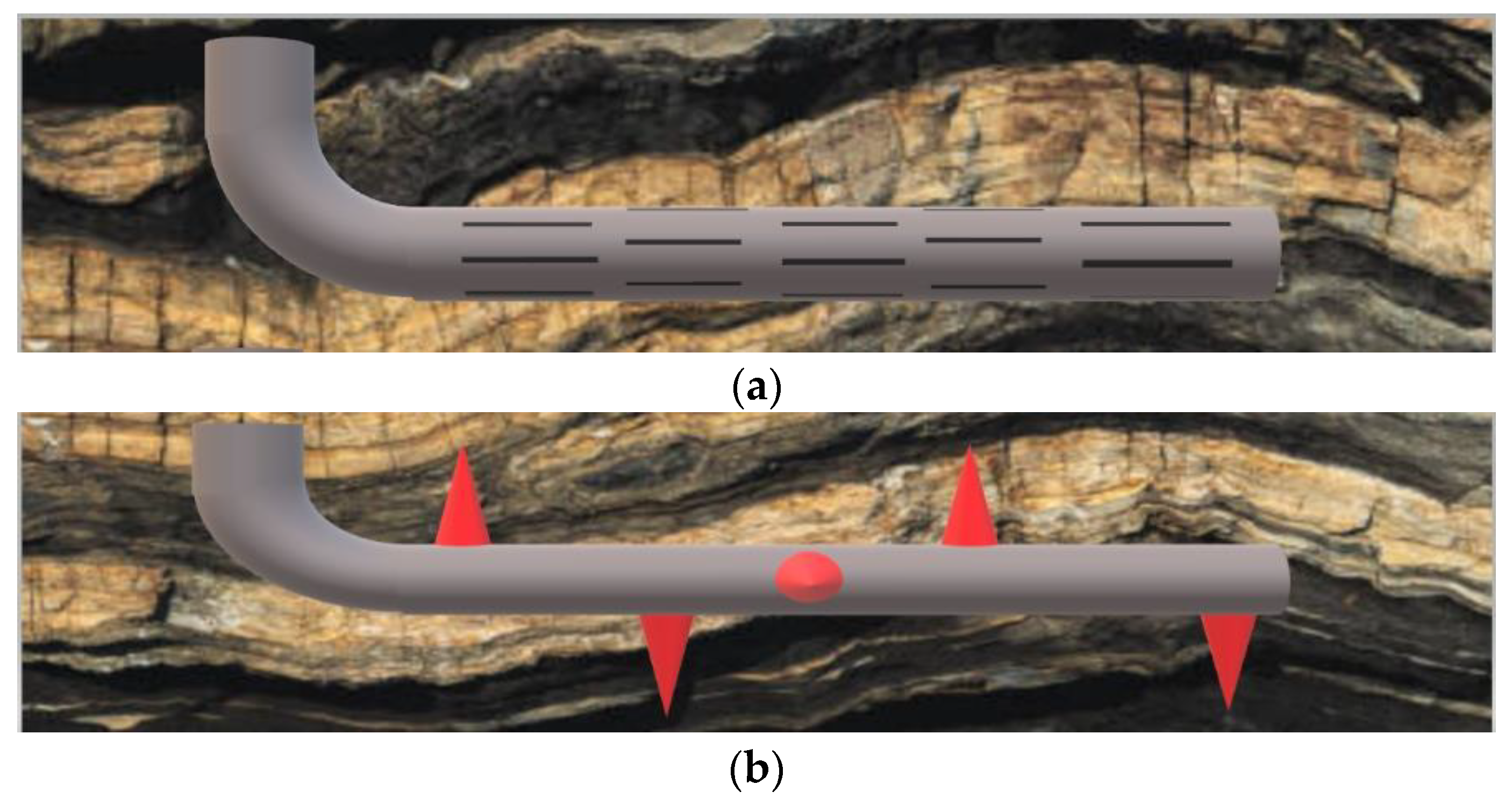
2.1. Model Assumptions

A black oil model is applied in this model to simulate the process of underground natural gas injection. To enhance the convergence of the simulation calculations, this paper assumes that:
  • the reservoir is isothermal, and the temperature is not affected by the injection of natural gas;
  • the frictional resistance to flow in the wellbore is neglected;
  • the dissolution of natural gas in formation water is neglected;
  • the interfacial tension is ignored;
  • the natural fractures are ignored.

2.2. Mathematical Equations

The behavior of gas flow in the vicinity of a horizontal well is characterized by high-speed and turbulent flows, rendering Darcy’s law insufficient to accurately describe its behavior. While Darcy’s law is a useful tool for modeling gas flow in other regions of the gas reservoir, in this context, it falls short due to the highly turbulent nature of the flow. As such, Forchheimer’s equation [38] is typically applied to account for the additional inertial force term that arises in the formulation of Darcy’s law.
d p d x = μ k u + β ρ u 2
where dp/dx represents the pressure gradient in Pa/m, μ is the viscosity in Pa·s, k is the permeability in m2, u is the fluid velocity in m/s, and ρ is the fluid density. β is the coefficient of inertial resistance in m−1, which can be expressed as the function of permeability.
β = b k a
where a and b are the laboratory measurement dimensionless parameters related to the formation properties.
However, it is challenging to utilize nonlinear flowing Equation (1) in reservoir numerical simulation due to its complexity and high computational requirements [39]. In reservoir numerical simulations, it is more common to incorporate a skin factor into the well productivity index to account for the additional pressure drop near the wellbore for simplicity and computation efficiency [40]. In this paper, Darcy’s equation considering gravity and the mass conservation equation are combined to obtain Equation (3) [41,42].
λ α ρ α ( P α ρ α g Z ) + q α w = δ δ t ϕ ρ α S α
where the subscript α represents the phase state and the superscript w represents the wellbore of the horizontal well. λ is the phase flow degree, D/(Pa·s). ρ is the phase density under reservoir condition in kg/m3; g is the gravitational acceleration, taken as 9.8 N/kg; Z is the depth in m; S is the phase saturation fraction; φ is the porosity fraction; t is the time in s; and q represents the coupled mass source term, kg/(m3·s), expressed as [43]:
q α w = J w λ α ρ α P b h P α ρ α g Δ Z
where Pbh is the pressure in the wellbore cell, and Jw is the well index in m3/(s·Pa). In the Cartesian coordinate system, the wellbore matrix well injectivity index can be expressed as [44]:
J w = θ k h ln ( r e / r w ) + S
where kh is the product of effective permeability and net thickness in D·m, rw is the horizontal well radius in m, and re is the equivalent radius in m. The dimensionless parameter θ varies with the coupling relationship between the wellbore matrix. S is the skin factor, which is dimensionless. For a slotted liner, the skin factor can be expressed as [29]:
s S L = s f o + s S L , l + s S L , r / k D s + ( f t , S L , l + β D s f t , S L , r ) F
where f is the turbulence scale factor and kDs is the ratio of k of the original formation to the k of the drilling fluid damaged zone. Subscript fo represents the skin factor of permeability reduction caused by drilling fluid, which is the function of the permeability of the origin formation k, permeability of the damaged formation ks, radius of the damaged zone rD, and anisotropy. Subscript t represents turbulence, subscript SL represents a slotted liner and subscripts l and r represent linear flow and radial flow, respectively. If the slotted liner is not plugged, the magnitude of the s and f in which the subscript l is located is 0. The s and f contributed by the linear and radial flows are a function of the slotted liner design parameters. F is the Forchheimer number related to flow rate expressed as [45]:
F = β ρ k μ q 2 π r w L
where q is the gas flow rate under reservoir conditions in m3/s and L is the length of a wellbore cell unit in m. The term F is the determined skin factor stur due to turbulence.
If the perforation length is smaller than the radius of the drilling fluid damage zone, the total skin factor can be expressed as [29,31,46]:
s p = s f o + s p 0 / k D s + β D s f t , p F
where s0p represents the skin deriving from a limited fluid flowing area. Subscript p represents perforation, ft,p is the turbulence scale factor of perforation, and βDs is the dimensionless coefficient of inertial resistance. Otherwise, the total skin factor can be expressed as [29,46]:
s p = s p o ^ + h p D k k c z 1 ln r c z r p + β c z β f t , p F
where subscript cz represents the crushed zone created during perforation, s p o ^ represents the perforation skin factor including the effect of formation damage, hpD is the dimensionless perforation spacing, rcz and rp represent the radius of the compact zone and radius of perforation, respectively, in m, and βcz is the coefficient of inertial resistance in the compact zone.

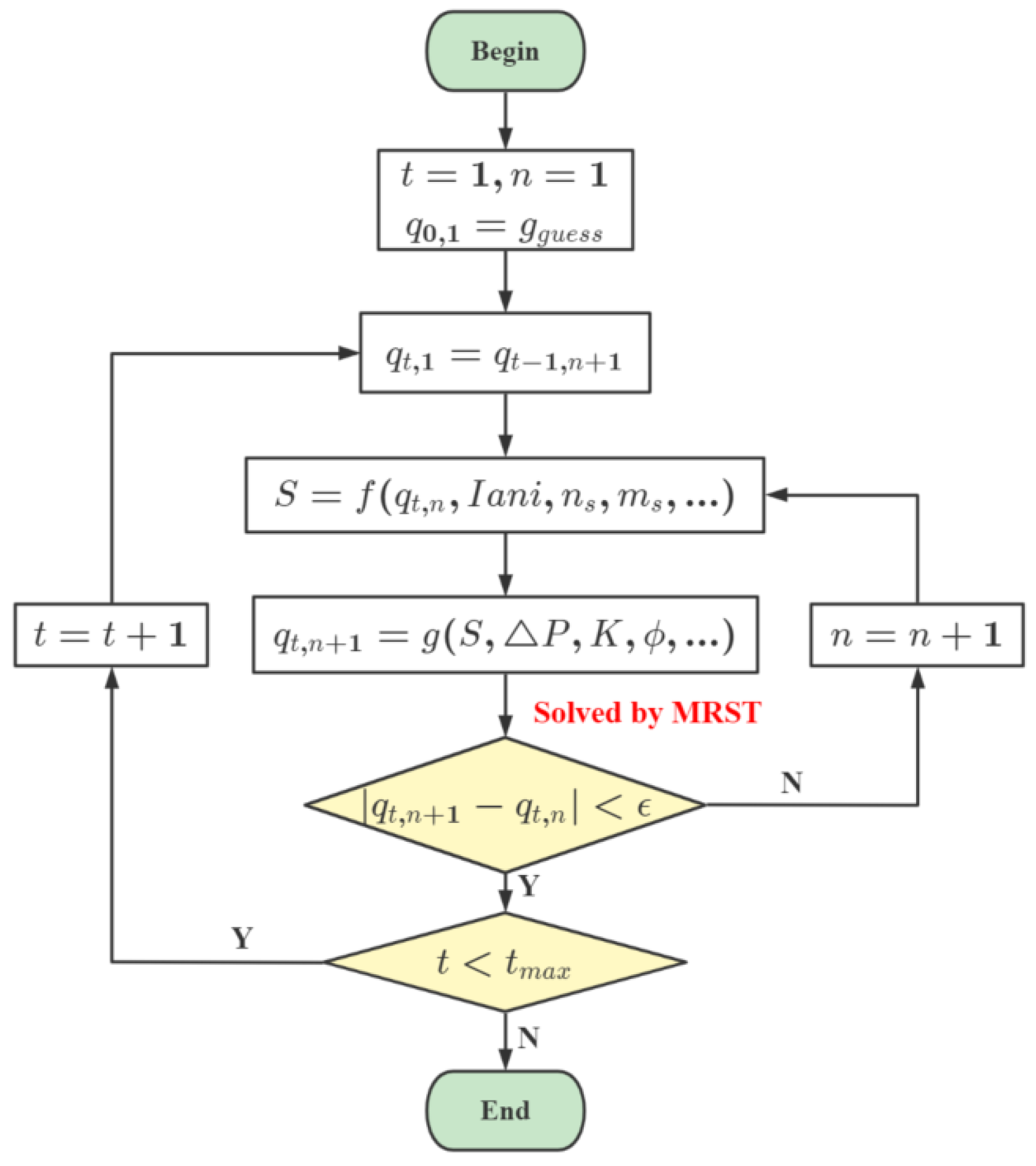
2.3. Numerical Calculation Method

When the horizontal well injection gas is at constant pressure, the flow rate q at the reservoir condition of each wellbore unit is unknown. Thus, F and the corresponding skin factor cannot be determined. Therefore, an extra uncoupled iteration method in every single time step is proposed in this paper, as shown in Figure 2. Here, t and n represent the time step and iteration step, respectively.
At the beginning of the initial time step (t = 1), it is first necessary to enter a hypothetical flow rate qguess and further use Equations (6)–(9) to determine the value of S. Then an updated flow rate q1,1 is calculated and used to calculate the next S in the next iteration step until the difference between the q1,n+1 and the q1,n calculated in the previous iteration is within an acceptable range, wherein the q1,n+1 calculated in the current iteration is used as the determined q at that time step. When the time step is larger than 2, the qt−1,n+1, the determined q at the previous time step, is used as qguess.
The control equations, such as Equation (3), are discretized by the two-point flux approximation method. The flow in a horizontal wellbore is considered a one-dimensional flow. The discrete set of equations is solved by MATLAB Reservoir Simulation Toolbox [47], which in turn solves the corresponding wellbore flow rate q for the corresponding reservoir, wellbore, and production conditions. MRST is a free open-source software for reservoir modeling and simulation, developed primarily by the Computational Geosciences group in the Department of Mathematics and Cybernetics at SINTEF Digital. In addition, the calculation and iterative parts of the skin factor were not originally provided by MRST but were independently developed and embedded into the MRST calculation process by the authors.

3. Parameters of Upper Wuerhe Formation, K75 Gas Reservoir

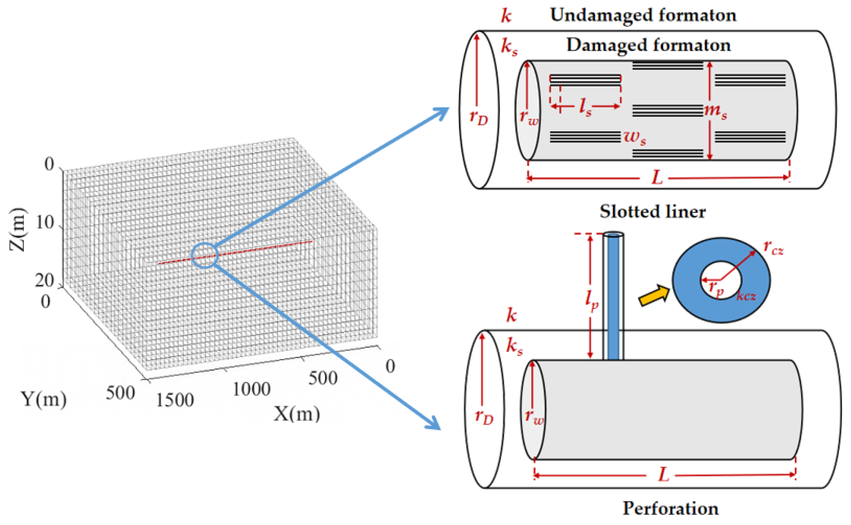
3.1. Numerical Model

In order to meet the seasonal peak-shaving requirements for natural gas, the K75 gas field in the Junggar Basin, northwest China, is being considered for conversion into a UGS, which can enable the storage of enriched, locally produced natural gas during periods of low demand that can then be supplied to urban areas during peak demand seasons. The K75 gas field commenced production in 1992, with a total of six wells. By the end of 2022, there were three production wells, with a cumulative gas production of 25.2 billion cubic meters, 57,000 tons of oil, and 3200 tons of water. Currently, the dynamic reserves of the K75 gas field stand at 28.0 bcm, with a 90% extraction rate and 2.8 bcm of remaining dynamic reserves. The K75 gas field is currently in a low-pressure and low-production stage, with a pressure coefficient of 0.13.
Located approximately 25 km southeast of Karamay City, the K75 gas reservoir benefits from convenient transportation and is only 15 km away from the gas network. The surface of the reservoir features a typical aeolian Gobi landscape with flat terrain and minimal sand dune undulation, which is advantageous for the construction of surface installations for the storage facility. The upper Wuerhe formation of the K75 gas reservoir has a simple structure, buried at a depth of 2750 m, with good closure integrity [48]. Classified as a medium-porosity, medium-permeability formation, the upper Wuerhe formation is estimated to have a natural gas storage capacity of 25 bcm, with a maximum working gas volume of up to 10 bcm.
The upper Wuerhe formation of the K75 gas reservoir is planned to be transformed into an underground storage facility using a single horizontal injection well. To investigate the impact of perforation and slotted liner completion on the injection capacity of this horizontal well, this study establishes a numerical model based on the parameters of a selected region within the K75 gas reservoir, predicting the horizontal well’s injection capacity under varying completion parameters. Rectangular reservoirs are 1500 m in length, 500 m in width, and 18.5 m in height, and are divided into 51 × 21 × 11 structured grids. Except for the closed boundary at the top and bottom of the reservoir, all the boundaries are constant pressure boundaries, and the boundary and initial reservoir pressures are 21 MPa. Natural gas is injected using a constant 1 MPa above the formation pressure in the base case. As shown in Figure 3, the horizontal wells distributed along the x axis are located at the center of the grid, and their length is 1000 m. The same completion method is used for the entire horizontal well, and the completion parameters do not vary with location. More reservoir and well parameters are shown in Table 1. The parameters are selected from the literature [49,50,51,52] and field survey data.
The effect of perforation and slotted liner on the gas injection capacity of horizontal wells at different parameters is reflected in the skin factor. In addition, the decrease in permeability around the horizontal well caused by drilling fluid intrusion and the crushed zone is not achieved by changing the permeability of the reservoir unit with which the wellbore is located but by changing the magnitude of the skin factor. Based on the common parameters for slotted liner and perforation completions [53,54,55], this paper employs the parameters and ranges shown in Table 2. It should be noted that, as the horizontal well has not yet been deployed, these parameters are based on assumptions.

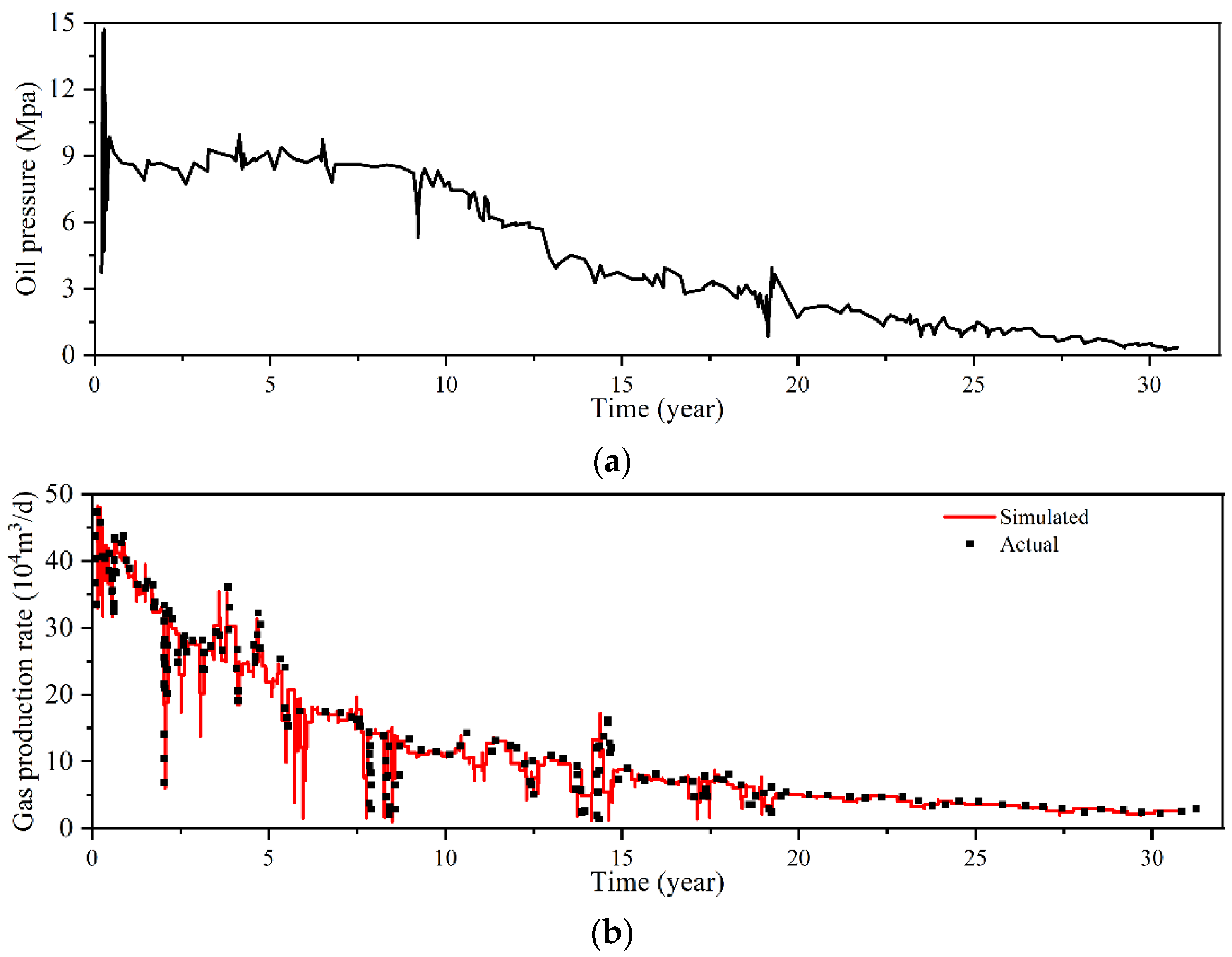
3.2. Model Validation

In order to verify the accuracy of the reservoir parameter selection in the numerical model, this paper selects the relationship between the gas production rate and time of Well K75 as a validation case. In 1992, when Well K75 was drilled to its target layer, a blowout occurred. The well was completed with an open hole completion, and currently, it contains 2476 m of drill pipe, 189 m of drilling collars, and connection tools. The test production yielded a daily gas output of 49.8 × 10⁴ m3. The well was produced with a 9 1/2-inch casing, with an initial daily output of 450,000 cubic meters, a current daily output of 29,000 cubic meters, and a cumulative production of 1.32 bcm. As shown in Figure 4, to maintain the flow rate, the gas production was sustained by continuously reducing the tubing pressure. Although the overall tubing pressure is decreasing, its values still fluctuate, causing the gas production rate to fluctuate as well. According to the tubing pressure, the simulated gas production rate matches the actual production rate quite well, with the average error between the simulated data and the measured data at 3.81%, thus verifying the accuracy of the reservoir parameter selection.
In the base case, the initial qguess is set to 3 × 10⁴ m3/d. As shown in Figure 5a, the smaller the convergence number, the lesser the number of convergence steps required for qg to reach the convergence condition. To ensure adequate calculation, the lower limit of the convergence step is specified as 2. When the convergence number ε is 10−13 m3/d, the maximum value of the convergence step is 4. In addition, different qguess values do not affect the final gas production rate.
Moreover, the difference in the calculated gas injection rates when using the coupled method and the uncoupled method is relatively small. As shown in Figure 5b, when the pressure difference dp is 10 MPa and k = 300 mD, the difference in gas production rates between the two methods is only 0.6%. However, the number of sub-iterations in the uncoupled method, that is, the number of sub-steps within each iteration step to obtain the result, is only 1/10 of that in the coupled method. The results demonstrate that the model can calculate the effect of gas injection capacity by turbulence damage through an accurate and effective uncoupled method.

4. Results and Discussions

4.1. Effect of Intrinsic Design Parameters

The gas injection rate of a horizontal well is influenced by its inherent design parameters, particularly when the formation experiences minimal drilling fluid damage and the gas injection rate is low. The formation damage caused by the drilling fluid is ignored in this sector. In addition, turbulence’s effect is minor because of a relatively low reservoir gas flow rate. Figure 6 shows the impacts of open area percentage, slot length, slot width, and slot angular distribution. The open area As is a key parameter that directly influences the gas injection ability of a horizontal well. A higher open area percentage of the slot liner typically translates to a larger flow area for the gas to enter the wellbore, resulting in the decrease of skin factor and the increase of gas rate. However, when the open area percentage increases from 5% to 6%, this increase in gas rate is only 24.4 m3, indicating a small effect on the increase in capacity when the open area percentage is large. Although a larger slot density leads to stronger gas injection capacity, it also results in lower wellbore strength, indicating that the open area needs to be controlled according to the mechanical strength of the tube [56]. The commonly used open area percentage of slotted liners generally ranges from 2% to 3%, with the maximum value not exceeding 10% [57,58].
The number of slots per meter can be expressed as:
N s = A s w s l s
When the As and ws are fixed, the increase in slot length leads to a decrease of Ns. However, the skin factor counter-intuitively increases with the increase of ls. This phenomenon can be explained by the fact that the increase in ls mainly leads to an offset between the increase of turbulence factor f and the decrease of radial flow skin sSL,r, in Equation (10). Nevertheless, when the turbulence effect is insignificant, there is a rise in the total skin factor. In contrast, when the As and ls are fixed, the increase of slot width leads to a more significant increase in skin factor because f and sSL,r, increase along with it. When ws increases from 0.2 mm to 1 mm, the skin factor increases to 2.15 times, resulting in a decrease of 4074 m3/d in gas injection volume. Fewer slot angular distributions can significantly increase radial skin factor. The skin factor is greater than 0.47 at ms below 4, while further increasing ms has less effect on skin factor and gas injection.
Similar to the open area of a screen tube, the perforation density determines the degree of connection between the horizontal well and the reservoir. However, the difference is that the value of reservoir damage does not tend to zero as the perforation density increases but rather appears to be negative. For example, when the perforation density is 3 shots/m, the reservoir damage is −0.25, as shown in Figure 7. When the perforation shot density is fixed, the increase in perforation length can significantly reduce the damage, and the skin factor and gas injection at a perforation length of 1.2 m are 7.7% and 3.66 times higher than those at a perforation length of 0.2 m, respectively. In contrast, when the perforation radius increases from 0.7 mm to 12.7 mm, the skin factor decreases by only 63.7%, resulting in a 1.16-fold increase in gas injection due to the fact that the radius of the crush zone is always set to be three times the shot-hole radius. When kv/kh < 1, the distribution of injection holes along the vertical direction is most favorable to improve fluid flow in the vertical direction. Therefore, the minimum formation damage occurs when the perforations are oriented at angles of 90° and 270° with respect to the horizontal axis. At a perforation orientation of 0, the skin factor decreases by 0.356. Although the effect of the perforation orientation is small in the case of this paper, the sensitivity of the skin factor to perforation orientation rises when drilling fluid damage is present.

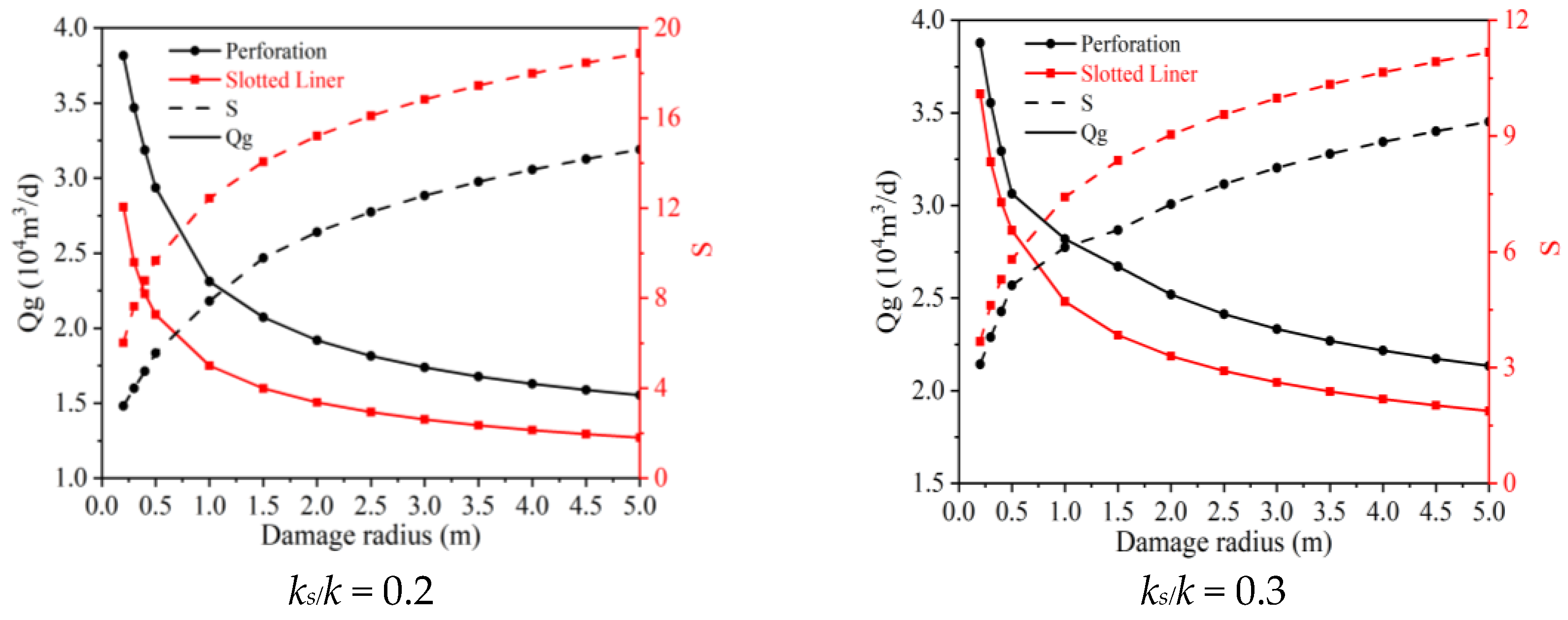
4.2. Effect of Formation Damage

The permeability reduction in the drilling fluid damage zone and its radius significantly impact the injection ability of the well. The reduced permeability can limit gas flow from the reservoir into the wellbore, decreasing the injection rate. However, slotted liner and perforation behave differently in reaction to formation damage, as shown in Figure 8. For example, when the reservoir damage is light (ks/k = 0.3), and the damage radius is lesser (0.2 m), the skin factor of the slotted liner is only 0.59 lower than the perforation. When ks/k is kept constant, the difference between the skin factor of the slotted liner and the injection hole increases with the increase of the damage radius, reaching a maximum value of 1.8 when rs = 1.5 m. Additionally, the difference between the two remains constant after rs > 1.5 m because the perforation completion can penetrate the damage zone to a certain extent. When rs > rp + rw, the principle that an increase in the damage radius leads to an increase in the skin factor is consistent with that of the slotted liner. However, when rs < rp + rw, an increase in the damage radius has much less of an effect on the skin factor of perforation compared to the slotted liner. When rs is within 1.5 m, the difference between the skin factor of the screen tube completion and the perforation completion decreases with the decrease of ks/k. When ks/k = 0.05, the difference in skin factor between the two reaches the maximum value of 40.87 at rs = 1 m, and the gas injection of perforation is 3.44 times that of the slotted liner. These results prove that perforation completions are more suitable for formations with great reservoir damage.

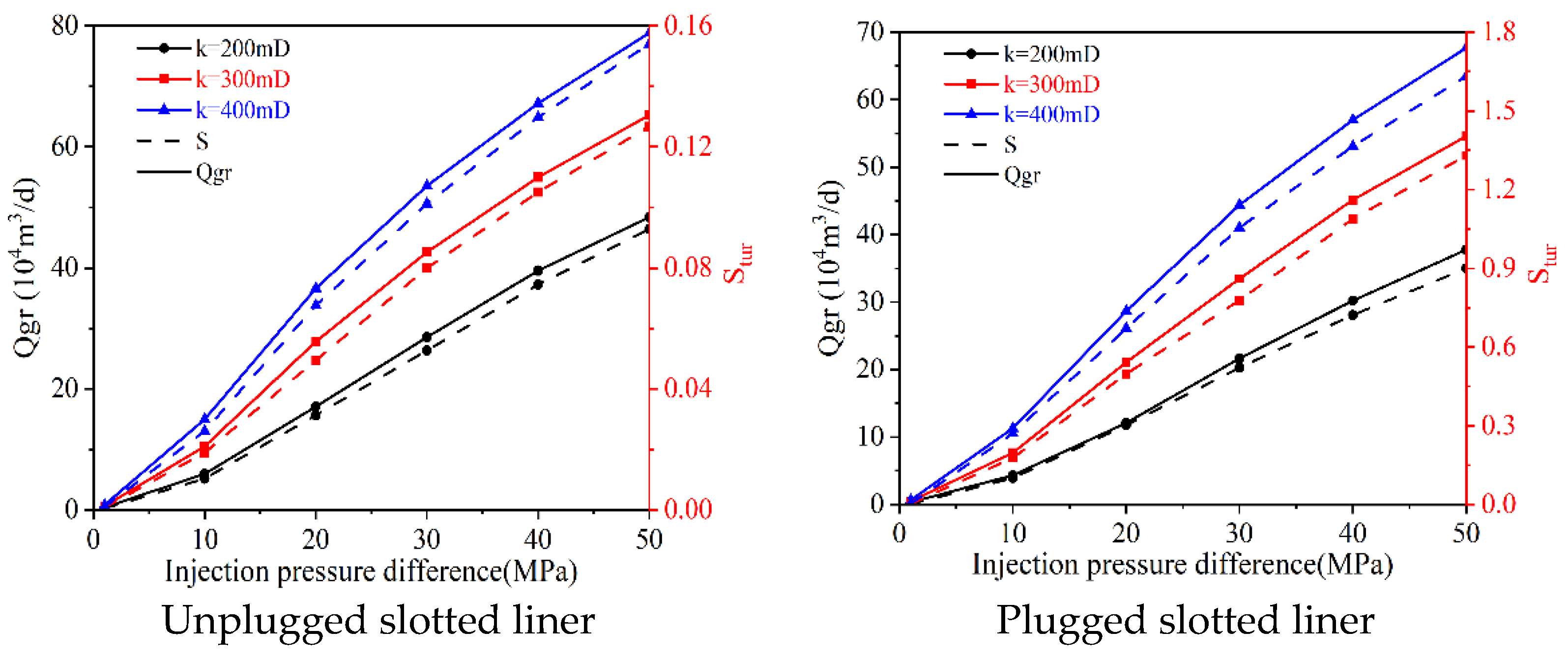
4.3. Effect of Injection Pressure

It is at higher reservoir permeability and larger injection fractures that the skin factor resulting from the turbulence effect is numerically close to the other skin factors. Therefore, in this section, the reservoir permeability is discussed in the range of 200–400 mD. When the pressure injection pressure is kept constant, the gas injection rate increases with the increase of permeability, as shown in Figure 9. The increase in gas injection rate caused a consequent rise in turbulence damage sfo, and in the unplugged slotted liner, the increase in skin factor ranged from 1.83 to 2.82 times as k increased from 200 mD to 400 mD. Similarly, the increase in injected gas volume due to the increase in injection pressure further leads to the increase in turbulence damage. Therefore, the relationship between pressure and gas injection rate is no longer linear as described in Darcy’s law, but the increasing value of the gas injection rate decreases with increasing pressure. The above nonlinear relationship is more obvious when the formation permeability and the gas injection pressure are large.
Moreover, the results show that the unplugged screen tube has less turbulence damage than the perforation, as shown in Figure 10. At k = 400 mD and dp = 50 MPa, the turbulence damage of the slotted liner is 15.9% of that of the perforation, resulting in a higher gas injection rate of 11.35 × 10⁴ m3/d compared to screen tube completions. However, the screen tube must be prevented from being plugged; otherwise, the damage from plugging can rise to 3 to 10 times the original level. It should be noted that the blockage of slotted liners generally occurs during the gas production phase rather than the injection phase. However, the same horizontal well can be used for both injection and production in a cyclic operation if the well is first used for gas production and experiences sand production blockage, which will also affect the subsequent injection capacity. At k = 400 mD, dp = 50 MPa, the injection rate of a plugged screen tube is 11.16 × 10⁴ m3/d lower than that of a non-plugged slotted liner. It should be noted that, generally, injection pump pressure greater than 50 MPa is not common. The higher pressure difference set in this paper is solely to emphasize the non-linear relationship between pressure difference and flow rate. At the same time, in some parts of the K75 gas reservoir, the formation pressure has already been depleted to 3.5 MPa, and a 50 MPa injection pressure difference has some guidance significance. In summary, the unplugged slotted liner suits high permeability and high injection pressure conditions.

5. Conclusions

Perforation and slotted liner completions are common completion methods in horizontal wells used as gas storage reservoirs. This paper investigates the gas injection capacity of two completion methods by developing a gas injection numerical model that accounts for the skin factor. Additionally, an uncoupled model is proposed, which considers the turbulent skin factor under constant pressure injection conditions. Finally, the effects of slotted liner and perforation design parameters, formation damage, and injection pressure on the damage are analyzed, leading to several key conclusions.
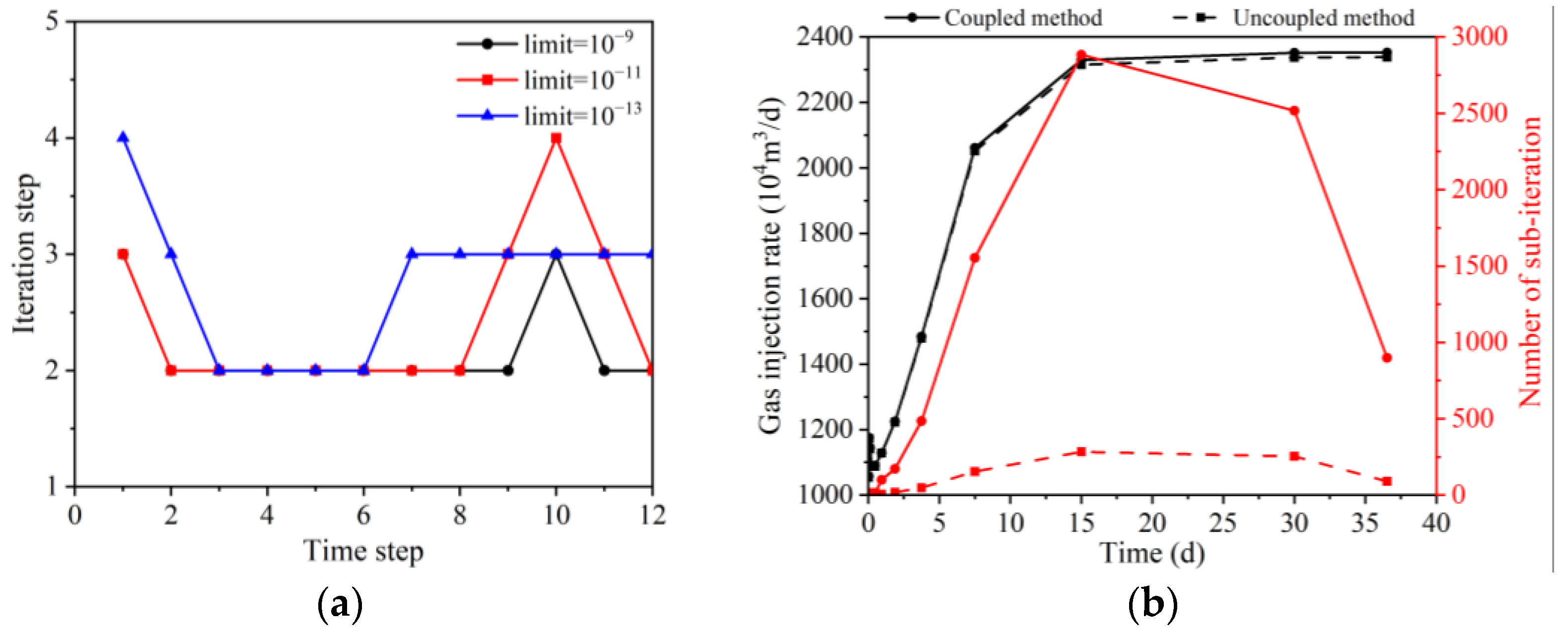
  • The uncoupled model determines the turbulence damage associated with the gas injection rate by iterative means. The results show that, even when the convergence conditions are in the range of 10−14, the number of convergence steps required within each time step is no greater than 4. Moreover, the difference between the results of the coupled method and the uncoupled method is small, but the uncoupled method can significantly reduce computational costs, demonstrating the method’s feasibility.
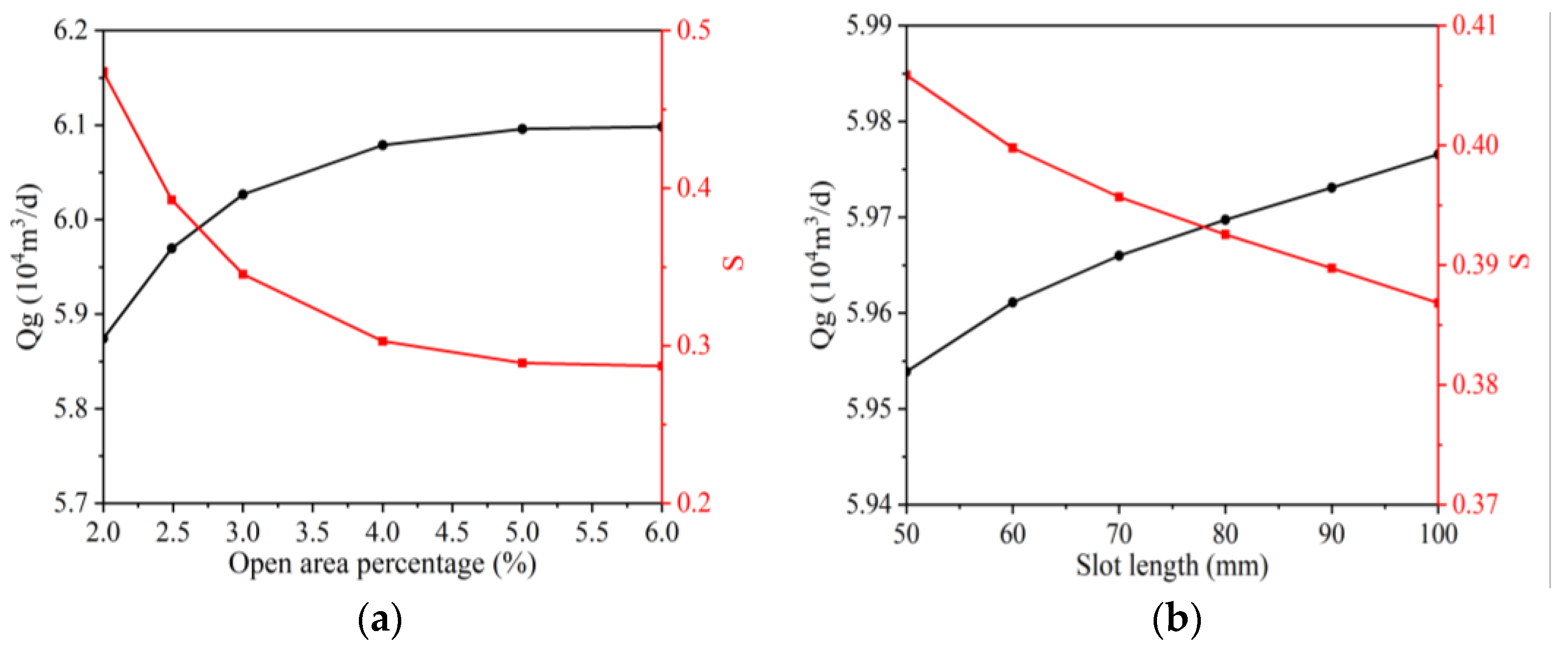
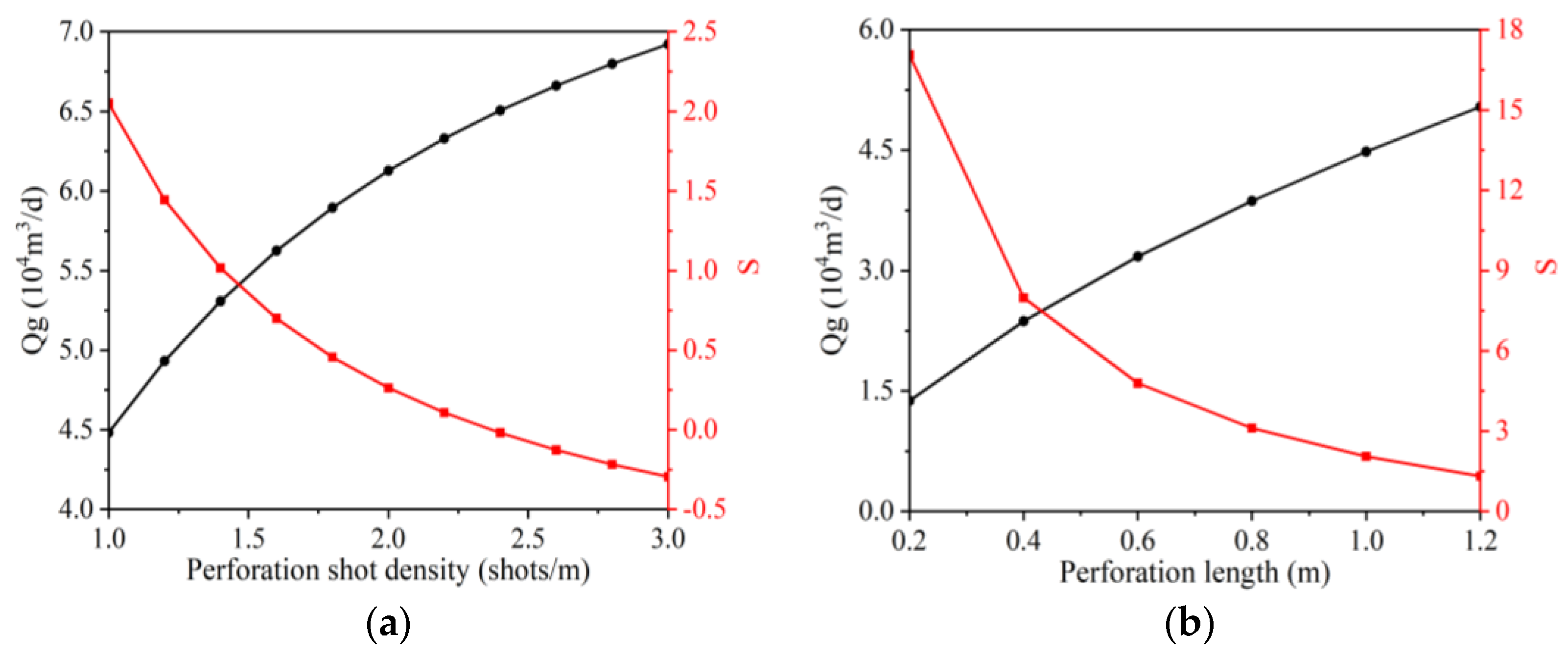
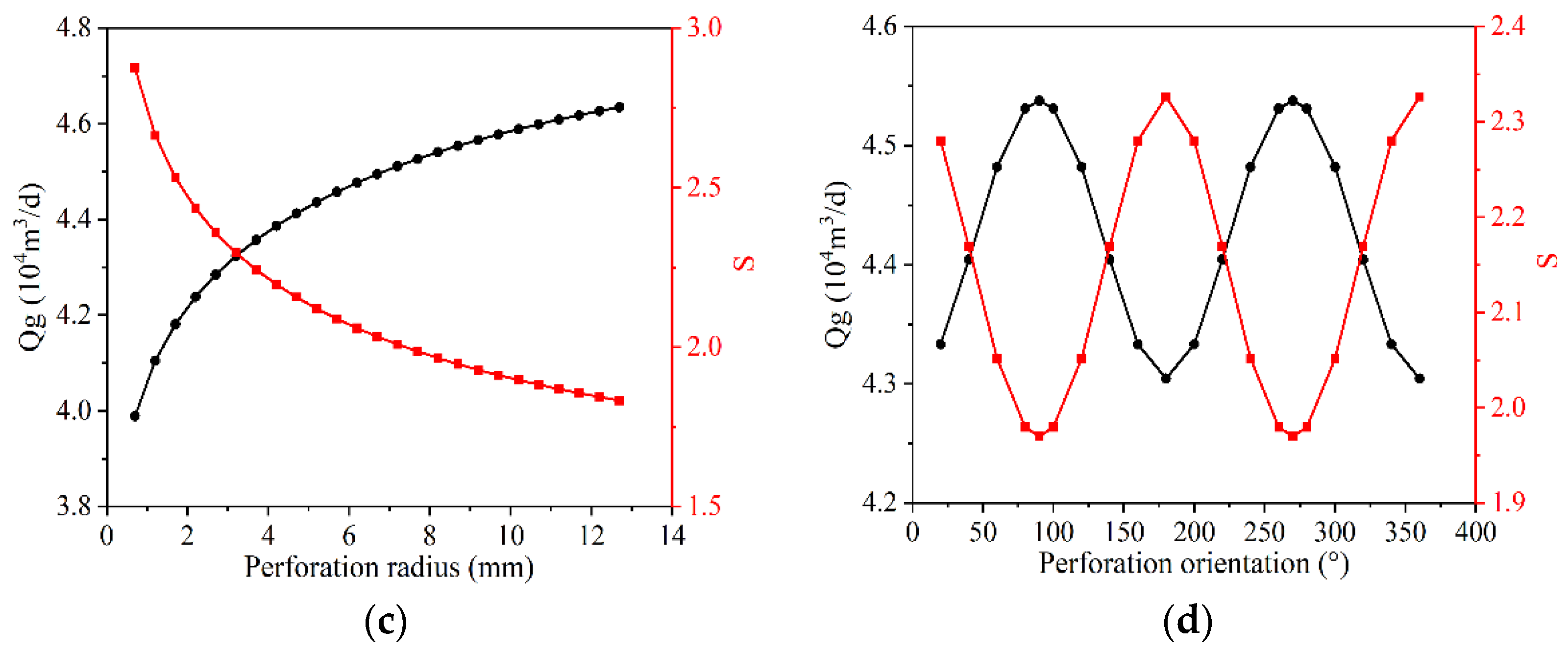
  • The design parameters of slotted liner and perforation completions mainly determine the value of the intrinsic skin factor of the horizontal well, especially the open area, and perforation density determines the connection degree between the horizontal well and the reservoir. However, a larger perforation density results in a negative skin factor, which means a better gas injection capability than an open hole completion.
  • Perforation is more suitable than slotted liner for application in severe reservoir damage formations due to the fact that they can penetrate a particular damage zone. When ks/k = 0.05, the difference in skin factor between the two can reach a value of 40.87, and the gas injection rate of perforation is 3.44 times that of the slotted liner.
  • It is easier to reduce turbulence damage for slotted liner completions than for perforation completions. At k = 400 mD, dp = 50 MPa, the turbulence damage of the slotted liner is 15.9% of that of the perforation. However, the slotted liner must be prevented from being plugged because the damage from plugging can rise to 3 to 10 times the original level.

Author Contributions

Conceptualization, J.W. and S.T.; methodology, T.W.; software, J.D. (Jiacheng Dai); validation, J.D. (Junjun Du), J.L. and H.L.; formal analysis, J.D. (Jiacheng Dai) and B.X.; investigation, J.D. (Jiacheng Dai) and Z.M.; resources, J.W.; data curation, J.W.; writing—original draft preparation, J.D. (Jiacheng Dai); writing—review and editing, J.D. (Jiacheng Dai); visualization, J.D. (Jiacheng Dai); supervision, S.T.; project administration, J.W.; funding acquisition, J.W. All authors have read and agreed to the published version of the manuscript.

Funding

This research was funded by the Project of Study on Well completion process and Parameter Optimization Design of reconstruction gas storage in Mahe and Ke75 Gas reservoirs, grant number [XQHX20220042].

Data Availability Statement

Data sharing not applicable. No new data were created or analyzed in this study. Data sharing is not applicable to this article.

Acknowledgments

We would like to express our heartfelt appreciation to the Computational Geosciences group in the Department of Mathematics and Cybernetics at SINTEF Digital for developing and providing the free open-source MATLAB Reservoir Simulation Toolbox (MRST) used in this research.

Conflicts of Interest

The authors declare no conflict of interest.

References

  1. Kirschen, M.; Risonarta, V.; Pfeifer, H. Energy efficiency and the influence of gas burners to the energy related carbon dioxide emissions of electric arc furnaces in steel industry. Energy 2009, 34, 1065–1072. [Google Scholar] [CrossRef]
  2. Li, Q.; Wu, J. Factors affecting the lower limit of the safe mud weight window for drilling operation in hydrate-bearing sediments in the Northern South China Sea. Géoméch. Geophys. Geo-Energy Geo-Resour. 2022, 8, 82. [Google Scholar] [CrossRef]
  3. Li, Q.; Han, Y.; Liu, X.; Ansari, U.; Cheng, Y.; Yan, C. Hydrate as a by-product in CO2 leakage during the long-term sub-seabed sequestration and its role in preventing further leakage. Environ. Sci. Pollut. Res. 2022, 29, 77737–77754. [Google Scholar] [CrossRef] [PubMed]
  4. Li, Q.; Wang, F.; Wang, Y.; Zhou, C.; Chen, J.; Forson, K.; Miao, R.; Su, Y.; Zhang, J. Effect of reservoir characteristics and chemicals on filtration property of water-based drilling fluid in unconventional reservoir and mechanism disclosure. Environ. Sci. Pollut. Res. 2023, 30, 55034–55043. [Google Scholar] [CrossRef]
  5. Dudley, B. BP statistical review of world energy 2022. In British Petroleum Statistical Review of World Energy; BP p.l.c., Ed.; Pureprint Group Limited: Uckfield, UK, 2022. [Google Scholar]
  6. Chen, Z.; Wang, H.; Li, T.; Si, I. Demand for storage and import of natural gas in China until 2060: Simulation with a dynamic model. Sustainability 2021, 13, 8674. [Google Scholar] [CrossRef]
  7. Katz, D.L.; Tek, M.R. Overview on underground storage of natural gas. J. Pet. Technol. 1981, 33, 943–951. [Google Scholar] [CrossRef]
  8. Xue, C.; Zhang, G.; Luo, T.; Wu, G.; Dai, L. Research and Application of One-Trip Casing Completion Technology in Hutubi Gas Storage. Xinjiang Oil Gas 2014, 10, 4. [Google Scholar]
  9. Abdel-Ghany, M.A.; Siso, S.; Hassan, A.M.; Pierpaolo, P.; Roberto, C. New Technology Application, Radial Drilling Petrobel, First Well in Egypt. In Proceedings of the Offshore Mediterranean Conference and Exhibition, Ravenna, Italy, 29–30 March 2011; OnePetro: Richardson, TX, USA, 2011. [Google Scholar]
  10. Zhang, J.; Tan, Y.; Zhang, T.; Yu, K.; Wang, X.; Zhao, Q. Natural gas market and underground gas storage development in China. J. Energy Storage 2020, 29, 101338. [Google Scholar] [CrossRef]
  11. Eren, T.; Polat, C. Natural gas underground storage and oil recovery with horizontal wells. J. Pet. Sci. Eng. 2020, 187, 106753. [Google Scholar] [CrossRef]
  12. Ferrandis, J.; Mateeva, A.; Jorgensen, P.; Lopez, J.; Dijkerman, H. Application of virtual-source technology to the Zuidwending gas storage project. Lead. Edge 2009, 28, 296–301. [Google Scholar] [CrossRef]
  13. Riddiford, F.; Wright, I.; Bishop, C.; Espie, T.; Tourqui, A. Monitoring geological storage: The in salah gas CO2 storage project. In Proceedings of the 7th International Conference on Greenhouse Gas Control Technologies, Vancouver, BC, Canada, 5–9 September 2004; pp. 1353–1359. [Google Scholar]
  14. Rutqvist, J. The geomechanics of CO2 storage in deep sedimentary formations. Geotech. Geol. Eng. 2012, 30, 525–551. [Google Scholar] [CrossRef]
  15. Sahin, S.; Abravci, S.; Tirek, A. Design and Status of the only Underground Gas Storage Project in Turkey after Three Years of Operation. In Proceedings of the SPE Russian Oil and Gas Exploration and Production Technical Conference and Exhibition, Moscow, Russia, 16–18 October 2012; OnePetro: Richardson, TX, USA, 2012. [Google Scholar]
  16. Fokker, P.; Wassing, B.; Van Leijen, F.; Hanssen, R.; Nieuwland, D. Application of an ensemble smoother with multiple data assimilation to the Bergermeer gas field, using PS-InSAR. Geomech. Energy Environ. 2016, 5, 16–28. [Google Scholar] [CrossRef]
  17. Oldenburg, C.M.; Bryant, S.L.; Nicot, J.-P. Certification framework based on effective trapping for geologic carbon sequestration. Int. J. Greenh. Gas Control. 2009, 3, 444–457. [Google Scholar] [CrossRef]
  18. Jones, V.; Drozd, R. Predictions of oil or gas potential by near-surface geochemistry. AAPG Bull. 1983, 67, 932–952. [Google Scholar]
  19. Gumrah, F.; Izgec, Ö.; Gokcesu, U.; Bagci, S. Modeling of underground gas storage in a depleted gas field. Energy Sources 2005, 27, 913–920. [Google Scholar] [CrossRef]
  20. Bagci, A.S.; Ozturk, B. Performance analysis of horizontal wells for underground gas storage in depleted gas fields. In Proceedings of the Eastern Regional Meeting, Lexington, KY, USA, 17–18 October 2007; OnePetro: Richardson, TX, USA, 2007. [Google Scholar]
  21. Zheng, D.; Hongcheng, X.; Jieming, W.; Junchang, S.; Kai, Z.; Chun, L.; Lei, S.; Ligen, T. Key evaluation techniques in the process of gas reservoir being converted into underground gas storage. Pet. Explor. Dev. 2017, 44, 840–849. [Google Scholar] [CrossRef]
  22. Tang, Y.; Ozkan, E.; Kelkar, M.; Sarica, C.; Yildiz, T. Performance of horizontal wells completed with slotted liners and perforations. In Proceedings of the SPE/CIM International Conference on Horizontal Well Technology, Calgary, AB, Canada, 6 November 2000; OnePetro: Richardson, TX, USA, 2000. [Google Scholar]
  23. Yang, G.; Wang, Z.M.; Peng, R.J.; Chen, T.; Ren, Z.X. Selection of Coal-Bed Methane Well Completion Method Based on Grey System Theory. Appl. Mech. Mater. 2013, 295–298, 3171–3174. [Google Scholar] [CrossRef]
  24. Bai, M.; Shen, A.; Meng, L.; Zhu, J.; Song, K. Well completion issues for underground gas storage in oil and gas reservoirs in China. J. Pet. Sci. Eng. 2018, 171, 584–591. [Google Scholar] [CrossRef]
  25. Roostaei, M.; Soroush, M.; Mohammadtabar, F.; Mohammadtabar, M.; Hosseini, S.A.; Mahmoudi, M.; Sadrzadeh, M.; Ghalambor, A.; Fattahpour, V. Design for reliability: Experimental and numerical simulation of cased and perforated completions with standalone screen. SPE Drill. Complet. 2021, 36, 680–706. [Google Scholar] [CrossRef]
  26. Szanyi, M.L.; Hemmingsen, C.S.; Yan, W.; Walther, J.H.; Glimberg, S.L. Near-wellbore modeling of a horizontal well with Computational Fluid Dynamics. J. Pet. Sci. Eng. 2018, 160, 119–128. [Google Scholar] [CrossRef]
  27. Li, B.; Sun, D.; Satti, R. Statistical analysis of significant factors affecting perforation flow at well scale. In Proceedings of the SPE International Symposium and Exhibition on Formation Damage Control, Lafayette, LO, USA, 21–23 February 2012; OnePetro: Richardson, TX, USA, 2012. [Google Scholar]
  28. Shareef, N.F.; Abdulwahid, M.A. Experimental and numerical study of slug flow in horizontal perforated wellbore. Geoenergy Sci. Eng. 2023, 221, 111239. [Google Scholar] [CrossRef]
  29. Furui, K. A Comprehensive Skin Factor Model for Well Completions Based on Finite Element Simulations; The University of Texas at Austin: Austin, TX, USA, 2004. [Google Scholar]
  30. Ibrahim, M.A.; Jaafar, M.Z.; Yusof, M.A.M.; Idris, A.K. A review on the effect of nanoparticle in drilling fluid on filtration and formation damage. J. Pet. Sci. Eng. 2022, 217, 110922. [Google Scholar] [CrossRef]
  31. Bennion, D.B. An overview of formation damage mechanisms causing a reduction in the productivity and injectivity of oil and gas producing formations. J. Can. Pet. Technol. 2002, 41, 29–35. [Google Scholar] [CrossRef]
  32. Wang, X.; Economides, M.J. Horizontal well deliverability with turbulence effects. In Proceedings of the 8th European Formation Damage Conference, Scheveningen, The Netherlands, 27–29 May 2009; OnePetro: Richardson, TX, USA, 2009. [Google Scholar]
  33. Abobaker, E.; Elsanoose, A.; Khan, F.; Rahman, M.A.; Aborig, A.; Butt, S. Comparison of crushed-zone skin factor for cased and perforated wells calculated with and without including a tip-crushed zone effect. Geofluids 2021, 2021, 3689964. [Google Scholar] [CrossRef]
  34. Tang, Y.; Yildiz, T.; Ozkan, E.; Kelkar, M. Effects of formation damage and high-velocity flow on the productivity of perforated horizontal wells. In Proceedings of the SPE Annual Technical Conference and Exhibition, San Antonio, TX, USA, 29 September–2 October 2002; OnePetro: Richardson, TX, USA, 2002. [Google Scholar]
  35. Mahmoudi, M.; Fattahpour, V.; Nouri, A.; Yao, T.; Baudet, B.A.; Leitch, M.; Fermaniuk, B. New criteria for slotted liner design for heavy oil thermal production. In Proceedings of the SPE Thermal Well Integrity and Design Symposium; Banff, AB, Canada, 28 November–1 December 2016, OnePetro: Richardson, TX, USA, 2016. [Google Scholar]
  36. Furui, K.; Zhu, D.; Hill, A.D. A comprehensive skin-factor model of horizontal-well completion performance. SPE Prod. Facil. 2005, 20, 207–220. [Google Scholar] [CrossRef]
  37. Bahrami, H.; Rezaee, R.; Ostojic, J.; Nazhat, D.; Clennell, B. Evaluation of damage mechanisms and skin factor in tight gas reservoirs. In Proceedings of the SPE European Formation Damage Conference, Noordwijk, The Netherlands, 7–10 June 2011; OnePetro: Richardson, TX, USA, 2011. [Google Scholar]
  38. Forchheimer, P. Wasserbewegung durch boden. Z. Des Ver. Dtsch. Ing. 1901, 45, 1781–1788. [Google Scholar]
  39. Shi, W.; Yang, T.; Liu, H.; Yang, B. Numerical modeling of non-Darcy flow behavior of groundwater outburst through fault using the Forchheimer equation. J. Hydrol. Eng. 2018, 23, 04017062. [Google Scholar] [CrossRef]
  40. Jeirani, Z.; Mohebbi, A. Estimating the initial pressure, permeability and skin factor of oil reservoirs using artificial neural networks. J. Pet. Sci. Eng. 2006, 50, 11–20. [Google Scholar] [CrossRef]
  41. Whitaker, S. Flow in porous media I: A theoretical derivation of Darcy’s law. Transp. Porous Media 1986, 1, 3–25. [Google Scholar] [CrossRef]
  42. Ahmed, T. Reservoir Engineering Handbook; Gulf Professional Publishing: Houston, TX, USA, 2018. [Google Scholar]
  43. Peaceman, D.W. Representation of a horizontal well in numerical reservoir simulation. SPE Adv. Technol. Ser. 1993, 1, 7–16. [Google Scholar] [CrossRef]
  44. Wan, J.; Penmatcha, V.; Arbabi, S.; Aziz, K. Effects of grid systems on predicting horizontal-well productivity. SPE J. 2000, 5, 309–314. [Google Scholar] [CrossRef]
  45. Zeng, F.; Zhao, G.; Xu, X. Transient pressure behaviour under non-Darcy flow, formation damage and their combined effect for dual porosity reservoirs. J. Can. Pet. Technol. 2009, 48, 54–65. [Google Scholar] [CrossRef]
  46. Karacan, C.; Halleck, P.M. Comparison of shaped-charge perforating induced formation damage to gas- and liquid-saturated sandstone samples. J. Pet. Sci. Eng. 2003, 40, 61–75. [Google Scholar] [CrossRef]
  47. Lie, K.-A. An Introduction to Reservoir Simulation Using MATLAB/GNU Octave: User Guide for the MATLAB Reservoir Simulation Toolbox (MRST); Cambridge University Press: Cambridge, UK, 2019. [Google Scholar]
  48. Nianzhou, L.; Bo, L.; Yi, Z.; Min, W.; Quan, W.; Hang, S. Sedimentary Characteristics and Connectivity of Upper Wuerhe Formation in Wellblock Ke 75, Karamay Oilfield. Xinjiang Pet. Geol. 2022, 43, 417. [Google Scholar]
  49. Tao, K.; Cao, J.; Wang, Y.; Ma, W.; Xiang, B.; Ren, J.; Zhou, N. Geochemistry and origin of natural gas in the petroliferous Mahu sag, northwestern Junggar Basin, NW China: Carboniferous marine and Permian lacustrine gas systems. Org. Geochem. 2016, 100, 62–79. [Google Scholar] [CrossRef]
  50. Wang, A.; Yi, L.; Xiang, B.; Li, J.; Fan, C.; Li, C.; Zhou, N.; Wang, Y. Origin of deep heavy oils in the northwestern Junggar Basin (NW China) and implications for gas migration. Energy Explor. Exploit. 2020, 38, 819–840. [Google Scholar] [CrossRef]
  51. Li, H.; Tang, H.-m.; Qin, Q.-r.; Fan, C.-h.; Han, S.; Yang, C.; Zhong, C. Reservoir characteristics and hydrocarbon accumulation of Carboniferous volcanic weathered crust of Zhongguai high area in the western Junggar Basin, China. J. Cent. South Univ. 2018, 25, 2785–2801. [Google Scholar] [CrossRef]
  52. Du Shekuan, L.J.; Dewen, L.; Mingchen, J.; Zhijie, N. Application of reservoir description technique in karamay oilfield. Xinjiang Pet. Geol. 1995, 16, 347. [Google Scholar]
  53. Xie, J. Slotted liner design optimization for sand control in SAGD wells. In Proceedings of the SPE Thermal Well Integrity and Design Symposium, Banff, AB, Canada, 23–25 November 2015; OnePetro: Richardson, TX, USA, 2015. [Google Scholar]
  54. Li, S.; Fan, Y.; Gou, B.; Zhang, H.; Ye, J.; Ren, J.; Xiao, Y. Simulation of filtration fields with different completion methods in carbonate gas reservoirs. Chem. Technol. Fuels Oils 2021, 57, 698–704. [Google Scholar] [CrossRef]
  55. Andrade, A.; Chango, M.; Atahualpa, G.; Correa, R.; Corona, G.; Calvopina, B.; Pico, J. Production Performance of Multiple Completion Designs: Openhole, Slotted Liner, ICD, and AICD: A Case Study for Water Control in Villano Field, Ecuador. In Proceedings of the SPE Annual Technical Conference and Exhibition, Dallas, TX, USA, 24–26 September 2018; OnePetro: Richardson, TX, USA, 2018. [Google Scholar]
  56. Placido, J.C.R.; Pasqualino, I.P.; Fonseca, C.E. Strength Analysis of Liners for Horizontal Wells. In Proceedings of the SPE Annual Technical Conference and Exhibition, Dallas, TX, USA, 9–12 October 2005; OnePetro: Richardson, TX, USA, 2005. [Google Scholar]
  57. Liu, X.; Morita, N. 3D Finite Element Analysis and Experimental Study of Stability of Slotted Liners. In Proceedings of the 52nd US Rock Mechanics/Geomechanics Symposium, Seattle, WA, USA, 17–20 June 2018; OnePetro: Richardson, TX, USA, 2018. [Google Scholar]
  58. Liu, X.; Morita, N. Collapse and bending analysis of slotted liners with laboratory tests and 3D FEM. SPE J. 2020, 25, 2353–2372. [Google Scholar] [CrossRef]
Figure 1. Horizontal well slotted liner (a) and perforation diagram (b).
Processes 11 01471 g001
Figure 2. Numerical calculation process with the uncoupled iteration method.
Processes 11 01471 g002
Figure 3. Schematic diagram of reservoir gridding and completion parameters. The red line indicates the horizontal well.
Processes 11 01471 g003
Figure 4. (a) Tubing pressure of Well K75 and (b) the comparison of simulated data and field data.
Processes 11 01471 g004
Figure 5. (a) The number of convergence steps required in the first 12 time steps for different convergence conditions (b) The gas injection rate and number of sub-iteration calculated by coupled and uncoupled method.
Processes 11 01471 g005
Figure 6. The gas flow rate and skin factor of the slotted liner at surface conditions. (a) Open area percentage. (b) Slot length. (c) Slot width. (d) Slot angular distribution.
Processes 11 01471 g006aProcesses 11 01471 g006b
Figure 7. The gas flow rate of perforation and the skin factor at surface conditions. (a) Perforation density. (b) Perforation length. (c) Perforation radius. (d) Perforation orientation.
Processes 11 01471 g007aProcesses 11 01471 g007b
Figure 8. The gas flow rate of the perforation and the slotted liner completions and the skin factor at surface conditions under different ks/k and damage radii.
Processes 11 01471 g008aProcesses 11 01471 g008b
Figure 9. The gas flow rate of the slotted liner and the skin factor at reservoir conditions under different permeability and injection pressure difference.
Processes 11 01471 g009
Figure 10. The gas flow rate of the perforation and the skin factor at reservoir conditions under different permeability and injection pressure difference.
Processes 11 01471 g010
Table 1. Basic reservoir properties.
ParametersValueUnit
Model dimension (x × y × z)1500 × 500 × 18.5m
Number of gridblocks (x × y × z)51 × 21 × 11
Horizontal well length1000m
Horizontal well diameter (2rw)139.7mm
Initial reservoir pressure21MPa
Reservoir temperature76°C
Reservoir permeability (kv/kh)26/22mD
Rock compressibility1 × 10−6psi−1
Gas specific gravity0.596
Gas compressibility10−4/barsa
Initial water saturation17%
Table 2. Basic slotted liner and perforation properties.
ParametersBase Case ValueRangeUnit
Damage zone radius (ks)10.2–5m
Damage zone permeability =k=0.05 k–0.3 kmD
Slotted liner
Slot width (ws)0.50.2–1mm
Slot length (wl)8050–100mm
Slot angular distribution (ms)51–12-
Open area percentage2.492–6%
Slot PatternStaggered--
Inline number1--
Perforation
Perforation length(lp)10.2–1mm
Perforation radius(wl)800.2–12.7mm
Number of slots per unit length (ns)1-/m
α600–360°
Crushed zone permeability=k/10-mD
Crushed zone radius (rcz)=3 rp-mm
Disclaimer/Publisher’s Note: The statements, opinions and data contained in all publications are solely those of the individual author(s) and contributor(s) and not of MDPI and/or the editor(s). MDPI and/or the editor(s) disclaim responsibility for any injury to people or property resulting from any ideas, methods, instructions or products referred to in the content.

