Abstract
Close-distance multilayer coal mining is common. Under the condition of extremely close-distance coal seams, it is extremely difficult to control the surrounding rock of large-span open-off cut roadways in multistress concentration areas. Based on the engineering background of the 23616 open-off cut roadway in Chaili Coal Mine, this paper investigated the influence of upper close seam mining on the stress and deformation of the lower large-span roadway in detail. The control effect of a high-strength prestressed yielding bolt and cable was analyzed systematically. The support system stress was coordinated by the yielding member to avoid excessive stress on the local support structure and reduce the stress concentration of the surrounding rock. Before and after the upper coal mining, the stress changed mainly on the left and right sides, and the displacement changed mainly on the right side and roof. The maximum deformation of the roof and the right side and the left side at two engineering observation sections was 85 mm, 61 mm, 48 mm and 68 mm, 53 mm, 46 mm, respectively. The surrounding rock control effect was relatively ideal, which can meet the needs of roadway installation support.
1. Introduction
Multiple minable coal seams are common in mining areas. If two coal seams are close together, their mutual influence will increase the difficulty of mining. Close coal seam mining methods are mainly divided into uplink and downlink. Uplifting is used only when the integrity of the upper coal seam can be ensured during the mining process of the lower coal seams [1,2,3]. This can not only prevent roof fall accidents but also avoid some other disasters [4,5,6]. The downlink mining method is relatively common. Scholars have conducted a lot of research on stress distribution, rock layer movement, and coal pillar positions of close-distance coal seams. The impact of mining dynamic loads and concentrated static loads between adjacent coal seams is a key consideration [7]. Shang Hefu et al. [8] investigated the process of chain pillar and gateroad failure in a lower coal seam. Zhang Wei et al. [9] built a mechanical model of floor failure of an upper coal seam. Li Yang et al. [10] obtained the development characteristics of full-cover rock fractures after mining from a GPR scan. Wang Xufeng et al. [11] analyzed the influence of a lower coal seam on the stress state of the surrounding rock using a numerical simulation. Gao Xu et al. [12] studied the different excavation schemes of the return air chute in a near-distance coal seam mining of Tashan Coal Mine. Ning Jianguo et al. [13] investigated the mining-induced overburden failures in close multiple-seam longwall mining.
In an extremely close coal seam, the lower coal roof is more easily affected by the dynamic load of upper coal mining [14,15,16]. Coal mining also belongs to the scope of solid mechanics. Based on the theory of solid mechanics, the stability of the rock stratum can be analyzed [17,18,19]. In the mining process, one end of the coal wall supports most of the weight of the cantilever rock above the working face, while the gangue behind the goaf only bears the weight of the compacted area [20,21,22]. The advanced and lateral abutment pressure of the working surface can be superimposed with higher concentration stress. The lateral abutment pressure of the two adjacent working surfaces will also be superimposed on the coal pillar. The concentrated stress passes through the coal pillar to the floor, resulting in more complicated stress on the lower roadway, which improves the difficulty of controlling the surrounding rock.
Generally, the roadways in the lower coal seam are in low-stress areas, which is conducive to the surrounding rock support. However, under the condition of extremely close-distance coal seams, the roadway must be arranged below the coal pillar, such as the 23616 open-off cut roadway. At present, the control of a high-stress roadway is mainly concentrated in the deep. Wang Qi et al. [23] investigated the failure mechanism of the surrounding rock with a deep high-stress and confined concrete support system. Liu Zhigang et al. [24] discussed the mechanism and effects of noncoupling stress-relief blasting under deep high stress. Zhang Jinpeng et al. [25] proposed a new prestressed yield bolt with the engineering background of Shangping roadway in Huafeng Coal Mine. There are fewer studies on the control of the roadway surrounding rocks in multiple-stress concentration areas.
The 23616 open-off cut roadway in the third coal seam of Chaili Mine, Shandong, China, was arranged directly below the coal pillar due to the leakage and fire hazards caused by the close-distance goaf. The 23616 coal face is 0.6–2.7 m away from the overlying goaf belonging to the extremely close coal seam. As shown in Figure 1, due to the impact of multiple mining-induced stresses, the 23616 open-off cut roadway stress is high, which makes it difficult to control the surrounding rock. Furthermore, the control of roadways in multistress concentration areas is still a worldwide problem.
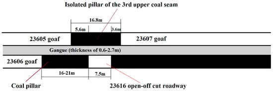
Figure 1.
Location diagram of 23616 open-off cut roadway in the 3rd coal seam of Chaili Mine, Shandong, China.
According to research experience, the peak of advanced abutment pressure often reaches 2–4 times the in situ stress [26,27]. Therefore, the superposition of triple advance pressure is at least five times the in situ stress, which greatly improves the difficulty of controlling the 23616 open-off cut roadway. Based on the engineering background of the 23616 open-off cut roadway in Chaili Coal Mine, this paper analyzed the stress distribution of the roadway in the stress concentration area. The influence of upper close seam mining on the stress and deformation of the lower large-span roadway was investigated in detail. The control effect of a high-strength prestressed yielding bolt and cable was analyzed systematically. The engineering application had important significance for the surrounding rock control of the large-span roadway in the stress concentration area.
2. Case Study
2.1. Geological Conditions
As shown in Figure 2, Chaili Coal Mine is located in Zaozhuang City, Shandong Province, China. The ground level is +35.81~+36.78 m. The level of the third coal seam is −333.5~−382.0 m. The third coal seam is divided into the upper layer and the lower layer due to a dirt band. The thickness of the third lower coal seam is 2.60~4.60 m, with an average of 3.90 m. Figure 3 is a comprehensive histogram of the roof and floor of the third coal seam. The basic roof is medium sandstone, with a thickness of 21.65~36.05 m and an average of 28.50 m. The direct floor is mudstone and sandy mudstone, with a thickness of 1.80~4.80 m and an average of 3.56 m. The basic floor is medium sandstone, with a thickness of 0.95~7.70 m and an average of 2.76 m.
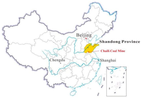
Figure 2.
Location of Chaili Coal Mine.
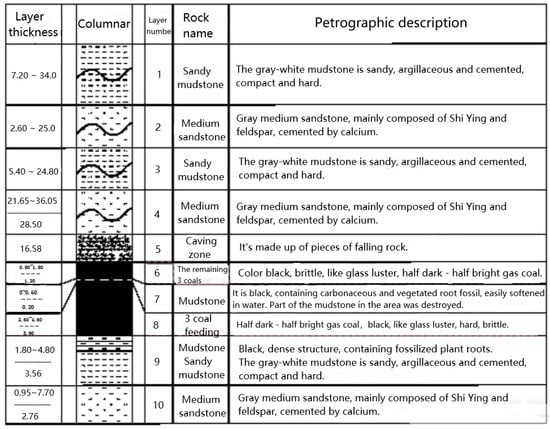
Figure 3.
A comprehensive histogram of the roof and floor of the 3rd coal seam.
The 23616 open-off cut roadway was originally designed to be located under the third upper coal goaf. The overlying rock was supported by a 12# I-steel shed. As the roof collapsed after the mining of the upper layer, and the distance between the lower layer and the goaf was relatively close, the cracks were connected, which might bring hidden dangers of air leakage and ignition. Therefore, the 23616 open-off cut roadway was arranged below the upper coal pillar, with a width of 16.8 m. The south was the 23607 goaf, the north was the 23605 goaf, and the west was the 23606 goaf. The distance between the 23616 coal face and the upper goaf was 0.6–2.7 m, with an average of 1.40 m. The width of the open-off cut roadway was 7.5 m, and the width of the left coal pillar was 16–21 m. Therefore, the 23616 open-off cut roadway was affected by the roof abutment pressure of the multiple goafs at the same time. In order to install the hydraulic support and scraper conveyor, the width of the 23616 open-off cut roadway must not be less than 7 m. Therefore, the support method of large-span open-off cut roadways in multistress concentration areas needs to be further investigated.
2.2. Evaluation of the Original Support Scheme
During the gateway excavation of the 23616 coal face, the front girder with a spacing of 2200 ± 200 mm was made of a 12# I-beam to temporarily support the roof. In the permanent scheme, a 12# I-steel shed and metal diamond mesh were used to support the roof, a bamboo fence and bolt were used to support the two sides, and an anchor net was used to support the heading coal wall. The maximum deformation of the surrounding rock after support exceeded 1000 mm. The support cost per meter of the roadway was more than USD 1000. The original support scheme was characterized by high cost, complex construction, slow speed, and poor effect of controlling the surrounding rock. Therefore, it was considered to control the large-span open-off cut roadway with active yielding support technology [28,29,30].
2.3. Stress Characteristics of Open-Off Cut Roadway in Stress Concentration Areas
The vertical stress of the close-distance coal seam under the coal face changes all the time. The maximum principal stresses of the coal seams under the coal pillar and the goaf are vertical stress and horizontal stress, respectively. The stress distribution of the lower coal seam roadway at different distances from the coal pillar is different, resulting in various forms of instability and failure.
There are only compression-shear and tensile failures of the roadway surrounding rock under static load [31,32]. The broken surrounding rock is mainly shear failure, with little tensile failure. The instability of the roadway is caused by the stress concentration of the surrounding rock and the reduction of its own strength after excavation [33,34]. Therefore, the root of roadway failure is that the shear stress of the surrounding rock gradually increases to exceed the shear strength. The stresses of the roadway surrounding rock and the overlying coal pillar are superposed, which greatly increases the vertical stress. After excavation, the vertical stress at the roof is released. Therefore, the high stress of the 23616 open-off cut roadway is mainly at the two sides and two shoulders.
3. Mechanism of Prestressed Yielding Support
3.1. Mechanism of Prestressed Yielding Bolt
On the basis of high prestress, a yielding bolt can release the elastic energy of a roadway after excavation. The deformation resistance of the bolt was enhanced to reduce the breaking of the rod caused by the rapid increase of stress so as to ensure early effectiveness. The stress–deformation characteristics of the prestressed yielding bolt are shown in Figure 4 [25]. Stages A–B represent the deformation of the yielding structure.
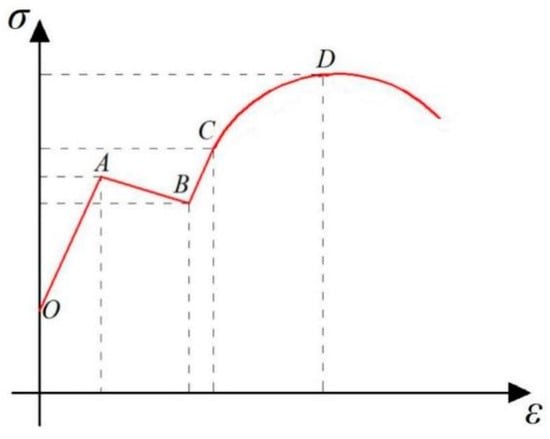
Figure 4.
The stress–deformation characteristics of the prestressed yielding bolt.
When the stress in the surrounding rock is released too quickly, the bolt may exhibit an increase in continuous working resistance. In the process of high-ground stress release, the bolt rod breaks when the stress exceeds the tensile strength. During the continuous and rapid increase in the bolt stress, if the yielding member is deformed, the surrounding rock stress will be released to a certain extent, exerting a pressure-relief effect. The state of rapid release of surrounding rock stress and rapid increase of bolt stress is broken, leading to the stress of the bolt and surrounding rock tending to stabilize, which not only protects the bolt from damage but also controls the deformation of the surrounding rock. Therefore, reasonable yielding deformation is very important to avoid the damage of bolt due to overloading. If the yielding deformation is too large, the roof subsidence will become larger or even separate, which will affect the active support effect of the bolt. If the yielding deformation is too small, the roof stress cannot be fully released, which may easily lead to the breaking of the bolt. In addition, the yielding member can cope with the impact of dynamic pressure on the supporting structure.
3.2. Coupling Effect of Yielding Bolt, Cable, and Surrounding Rock
- (1)
- Coupling of bolt and cable support system
The yielding member, damping nut, and drag-reducing washer greatly improve the stress of the bolt. Through small drilling and resin anchoring agent, the anchor tightness between bolt and surrounding rock is enhanced. Figure 5 shows high-strength prestressed bird-nest cable. Through the three “bird’s nests” at the end of the cable, the resin cartridge is closely coupled with the cable and surrounding rock to improve the anchoring force.
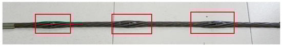
Figure 5.
High-strength prestressed bird-nest cable.
The support system stress is coordinated by the yielding member to avoid excessive stress on the local support structure and reduce the stress concentration of the surrounding rock;
- (2)
- Coupling of yielding bolt and surrounding rock
The prestressed yielding bolt has the working characteristics of strong yielding performance, large elongation, high strength, and high rigidity [35,36,37]. The rock mass, which is easy to loosen after peaks, can be formed into a combined support circle with certain bearing capacity and adaptable to deformation. The anchor–rock mass is a rock–beam structure before plastic failure and can continue to bear after plastic failure.
4. Numerical Simulation and Analysis
4.1. Stress Characteristics of the 23616 Open-Off Cut Roadway
The width of the 23616 open-off cut roadway was 7300 mm, which caused a large bending deflection of the roof. The size of the numerical model was determined based on the size of the 23616 open-off cut roadway and the impact area of mining in the third upper and lower coal seams. The influence range of general mining dynamic stress did not exceed 200 m, and the significant influence range was even less than 50 m. Therefore, according to the mechanical parameters of the roof–floor rock stratums of the third lower coal seam, a numerical model with the size of 200 × 125 × 100 m and 369,000 grids was established using the Mohr Coulomb model. Figure 6 shows the numerical simulation and boundary conditions. According to the buried depth, a vertical stress of 10 MPa was applied to the top. The left, right, and bottom boundaries were fixed constraints. After the roof rock stratum of the 23606 coal face was stable, the 23616 open-off cut roadway was excavated at the position 18 m away from the goaf. The stress and displacement characteristics of the 23616 open-off cut roadway under the mining and nonmining conditions of the third upper coal seam were compared.
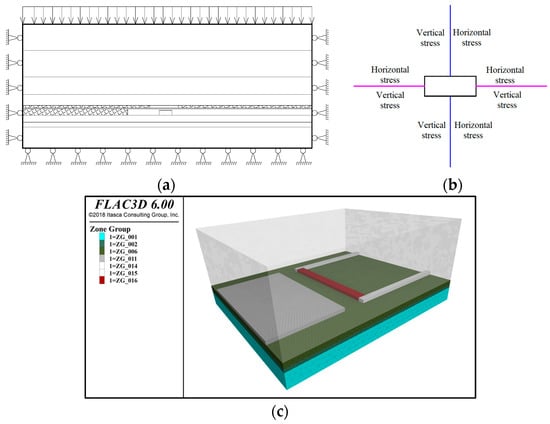
Figure 6.
Numerical simulation and boundary conditions. (a) Boundary conditions of numerical model; (b) applying stress; (c) three-dimensional numerical model.
Figure 7 and Figure 8, respectively, show the stresses of the 23616 open-off cut roadway under the nonmining and mining conditions of the third upper coal seam. It can be seen from Figure 7 and Figure 8 that the distribution of horizontal stress and vertical stress of the 23616 open-off cut roadway changed significantly after the mining of the upper coal seam; especially, the range of stress concentration expanded.
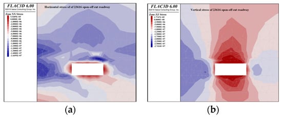
Figure 7.
Stress diagram of 23616 open-off cut roadway under the nonmining conditions of upper coal seam. (a) Horizontal stress; (b) vertical stress.
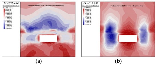
Figure 8.
Stress diagram of 23616 open-off cut roadway under the mining conditions of upper coal seam. (a) Horizontal stress; (b) vertical stress.
The distance in Figure 9 refers to the distance between the surrounding rock and the roadway surface. As the distance increased, the depth of the surrounding rock increased. As shown in Figure 9a, under the nonmining conditions of the upper coal seam, the vertical stress of the left side was about 20~25 MPa, with a peak value of 26 MPa. The vertical stress on the right side was about 13~17.5 MPa, with a peak value of 21 MPa. The horizontal stress of the roof was about 6~12 MPa, with a peak value of 17.5 MPa. In the mining process of the 23606 coal face, the third upper coal seam was seriously damaged due to the bending and collapse of the third lower coal seam roof. The 23616 open-off cut roadway was affected by the advanced abutment pressure of the 23606 coal face.
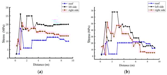
Figure 9.
Stress of 23616 open-off cut roadway under the nonmining and mining conditions of upper coal seam. (a) The nonmining conditions of upper coal seam; (b) the mining conditions of upper coal seam.
As shown in Figure 9b, under the mining conditions of the upper coal seam, the vertical stress of the left side was about 15~45 MPa, with a peak value of 65 MPa. The vertical stress on the right side was about 5~35 MPa, with a peak value of 52 MPa. The horizontal stress of the roof was about 3~20 MPa, with a peak value of 21 MPa.
After the mining of the 23605 and 23607 faces, the stress of the 23616 open-off cut roadway surrounding rock changed significantly, especially on the two sides. Through comparison, the peak stresses of the left side, right side, and roof increased by 39 MPa, 31 Mpa, and 3.5 MPa, respectively, with an increase of 150%, 147%, and 20%. After the mining of the third upper coal seam, the advanced abutment pressure of the 23605 and 23607 coal faces acted on the coal pillar, which greatly aggravated the stress concentration of the 23616 open-off cut roadway. In addition, the advanced abutment pressure of the 23606 coal face further increased the stress of the cut roadway.
4.2. Prestressed Yielding Support for the 23616 Open-Off Cut Roadway
Through a numerical simulation, the control effect of the yielding bolt and cable and a single hydraulic prop for the large-span 23616 open-off cut roadway was evaluated.
4.2.1. Support Scheme of the 23616 Open-Off Cut Roadway
The width and height of the 23616 open-off cut roadway were 7300 mm and 2800 mm. The diameter and length of the bolt were 20 mm and 2400 mm. The spacing–discharge distances on the roof and the sides were 850 × 1000 mm and 1000 × 1000 mm. The diameter and length of the cable were 17.8 mm and 7000 mm. The spacing–discharge distances were 850 × 1000 mm. Each discharge of six cables was arranged. Each bolt and cable were matched with a yielding pipe. Each discharge of two single hydraulic props was arranged. The spacing–discharge distance was 3200 × 500 mm. The support unit of the 23616 open-off cut roadway is shown in Figure 10.
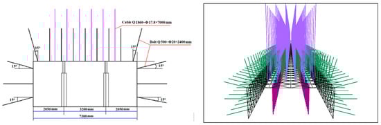
Figure 10.
The support unit of 23616 open-off cut roadway.
4.2.2. Stress and Displacement of the 23616 Open-Off Cut Roadway after Support
Figure 11, Figure 12 and Figure 13, respectively, show the displacements, stresses, and monitoring data of the 23616 open-off cut roadway after support under the nonmining conditions of the third upper coal seam. It can be seen from Figure 11 and Figure 12 that under the nonmining conditions of the upper coal seam, the 23616 open-off cut roadway had the most obvious roof deformation due to its large width. The stress distribution of the surrounding rock was relatively uniform, and the concentration coefficient was small.
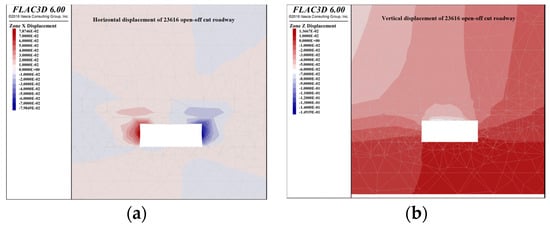
Figure 11.
Displacement diagram of 23616 open-off cut roadway after support under the nonmining conditions of the upper coal seam. (a) Horizontal displacement; (b) vertical displacement.
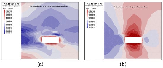
Figure 12.
Stress diagram of 23616 open-off cut roadway after support under the nonmining conditions of the upper coal seam. (a) Horizontal stress; (b) vertical stress.
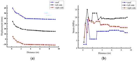
Figure 13.
Monitoring data of 23616 open-off cut roadway after support under the nonmining conditions of the upper coal seam. (a) Displacement; (b) stress.
Figure 13 shows that the maximum horizontal displacements of the left side, right side, and roof of the 23616 open-off cut roadway after the support of the yielding bolt and cable and single hydraulic prop were 35 mm, 5 mm, and 60 mm, respectively. The vertical stress of the left side was about 20~23 MPa, with a peak value of 25 MPa. The vertical stress on the right side was about 13~17 MPa, with a peak value of 19 MPa. The horizontal stress of the roof was about 6~15 MPa, with a peak value of 17 MPa.
Figure 14, Figure 15 and Figure 16, respectively, show the displacements, stresses, and monitoring data of the 23616 open-off cut roadway after support under the mining conditions of the third upper coal seam. It can be seen from Figure 14 and Figure 15 that after mining of the upper coal seam, the deformations of the left and right sides of the 23616 open-off cut roadway tended to be equal; especially, the stress and displacement were basically symmetrical.
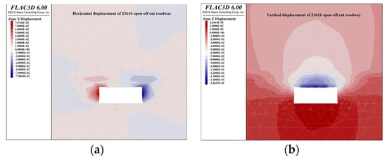
Figure 14.
Displacement diagram of 23616 open-off cut roadway after support under the mining conditions of the upper coal seam. (a) Horizontal displacement; (b) vertical displacement.
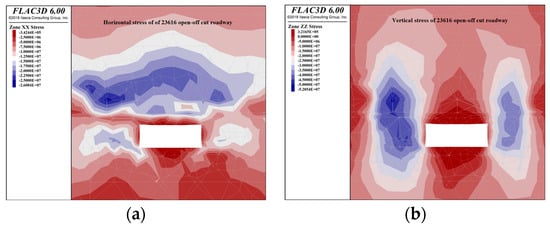
Figure 15.
Stress diagram of 23616 open-off cut roadway after support under the mining conditions of the upper coal seam. (a) Horizontal stress; (b) vertical stress.
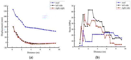
Figure 16.
Monitoring data of 23616 open-off cut roadway after support under the mining conditions of the upper coal seam. (a) Displacement; (b) stress.
Figure 16a shows that the maximum horizontal displacements of the left side, right side, and roof of the 23616 open-off cut roadway were 60 mm, 60 mm, and 125 mm, respectively, after the support of the yielding bolt and cable and single hydraulic prop. Figure 16b shows that the vertical stress of the left side was about 15~45 MPa, with a peak value of 62 MPa. The vertical stress on the right side was about 5~45 MPa, with a peak value of 52 MPa. The horizontal stress of the roof was about 3~20 MPa, with a peak value of 27 MPa.
4.2.3. Comparison and Analysis
The stress concentration of the surrounding rock after support shifted to the depth. The surface surrounding rock had more uniform stress and significantly reduced displacement. This was because the surface surrounding rock was most affected by mining. With the increase of the distance from the roadway surface, the degree of influence on the rock stratum gradually decreased.
After upper coal mining, the peak stresses of the left side, right side, and roof increased by 37 MPa, 3 Mpa, and 10 MPa compared with that of upper coal nonmining, with an increase of 148%, 173.7%, and 58.8%. The maximum displacement of the left side, right side, and roof increased by 15 mm, 55 mm, and 65 mm, respectively, with an increase of 42.9%, 1100%, and 108.3%.
Before and after upper coal mining, the stress changed mainly on the left and right sides, and the displacement changed mainly on the right side and roof. It showed that upper coal mining had a comprehensive loosening effect on the lower coal. The roof and left side coal of the 23616 open-off cut roadway was obviously affected by the 23606 goaf. In addition, the mechanical properties of the rock mass and coal were significantly reduced, with even some of them entering a plastic failure state. Therefore, due to the influence of the left goaf, mining had the greatest impact on the right-side coal, although the displacement of the 23616 open-off cut roadway after support obviously increased before and after upper coal mining. However, the maximum roof subsidence was only 125 mm, which was within the allowable range.
5. Engineering Application and Evaluation
In engineering practice, the composite support scheme of the yielding bolt and cable and single hydraulic prop was adopted. The detailed parameters were the same as those in Section 4.2.1. The roof displacement of the 23616 open-off cut roadway was monitored. The monitoring results were analyzed to further evaluate the rationality of the scheme.
5.1. Support Scheme during Construction
The supporting scheme was supplemented as follows: The tray sizes matching the bolt and cable were 150 × 150 × 10 mm and 300 × 300 × 12 mm. The outer diameter, thickness, and height of the bolt yielding pipe were 32 mm, 3.0 mm, and 40 mm, respectively. The yielding load was 100 ± 20 kN. The outer diameter, thickness, and height of the cable yielding pipe were 32 mm, 3.5 mm, and 40 mm, respectively. The yielding load was 160 ± 20 kN.
Figure 17 shows the left-handed prestressed yielding bolt. Its specific parameters are shown in Table 1. Table 2 shows the specific parameters of the cable.
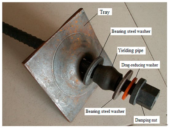
Figure 17.
The left-handed prestressed yielding bolt.

Table 1.
The specific parameters of left-handed prestressed yielding bolt.
Table 2.
The specific parameters of cable.
The size of the welded steel ladder was 4000 × 80 mm. A cold-drawing steel welded mesh with a grid of 100 × 100 mm was laid on the roof. A diamond braided steel wire mesh with a grid of 60 × 60 mm was laid on two sides. Each bolt and cable were matched with one and three pieces of k2570 resin. The setting load of the single hydraulic column with a diameter of 100 mm must not be less than 90 kN.
5.2. Results and Evaluation
Multiple monitoring sections were arranged on the 23616 open-off cut roadway to read the displacements of the roof and two sides. Three monitoring points were set at each section, respectively, on the roof, left side, and right side. Two representative monitoring sections were selected for analysis and named as 1 # and 2 #. Two monitoring sections were located in the middle of the test roadway, which was less affected by boundary factors. The roof monitoring point was located in the middle of the roof. The monitoring points on both sides were located at a height of 1 m from the floor. Figure 18 shows the displacement of the roof and two sides of observation section 1 # and 2 # over time.
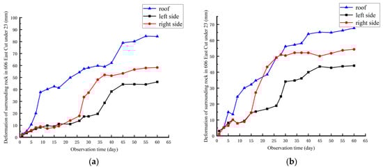
Figure 18.
The displacement of the roof and two sides of observation section 1 # and 2 # over time. (a) 1# monitoring sections; (b) 2# monitoring sections.
It can be seen from Figure 18 that the maximum deformations of the roof, the right side, and the left side at observation sections 1 # and 2 # were 85 mm, 61 mm, 48 mm and 68 mm, 53 mm, 46 mm, respectively. The subsidence of the roof rock layer was the largest but within the allowable range. The reason is that the bending deflection of the large-span open-off cut roadway roof under the coal pillar was large.
The subsidence of the roof rock stratum was faster in the first 12 days, slower at 30 days, and gradually stabilized at 45 days. The deformation of the two sides was relatively small in the first 25 days, relatively fast in 25 to 40 days, and gradually stabilized after 40 days. Although the coal pillar stress could be transmitted to the two sides, the side coal was complete, and the roof rock stratum was broken, so the initial deformation of the roof was faster, and the sides were slower. As the right side was more obviously affected by the stress concentration of the coal pillar, the deformation was greater than that of the left side. The results showed that the surrounding rock control effect was relatively ideal, which could meet the needs of roadway installation support.
6. Discussion and Conclusions
This paper took the 23616 open-off cut roadway in the third coal seam of Chaili Mine as the engineering background to explore the support mechanism and methods of large-span roadways in multistress concentration areas. The effectiveness of prestressed yielding support was verified through engineering monitoring. According to the burial depth, the vertical stress here should be approximately 10 Mpa. However, under the movement of the overlying strata after coal seam mining, the stress distribution is uneven, resulting in stress concentration. Under the mining conditions of the upper coal seam, the maximum vertical stress of the left side and right side was about 65 MPa and 52 MPa. Compared to the nonmining conditions of the upper coal seam, the peak stresses of the left side and right side increased by 39 MPa and 31 MPa, respectively, with an increase of 150% and 147%. By coordinating the prestressed yielding bolt, prestressed yielding cable, and the surrounding rock, not only did it avoid the breakage of the bolt and cable in the stress concentration area, but the stress in the surrounding rock was also balanced. The numerical simulation and engineering application results showed that the deformations of the two sides and roof of the 23616 open-off cut roadway after support were 46–61 mm and 68–125 mm. The main conclusions of the paper are as follows:
- (1)
- The 23616 open-off cut roadway in the third coal seam of Chaili Mine was arranged directly below the coal pillar. The original steel shed support scheme was characterized by high cost, complex construction, slow speed and a poor surrounding rock control effect. This study controlled the large-span open-off cut roadway in a multistress concentration area using active yielding support technology;
- (2)
- The prestressed yielding bolt has the working characteristics of strong yielding performance, large elongation, high strength, and high rigidity. The support system stress was coordinated by the yielding member to avoid excessive stress on the local support structure and reduce the stress concentration of the surrounding rock. Reasonable yielding deformation is very important to avoid damage to the bolt due to overloading;
- (3)
- The stress concentration of the supported surrounding rock shifted to the depth. The stress of the surface surrounding rock was more uniform, and the displacement was significantly reduced. Before and after upper coal mining, the stress changed mainly on the left and right sides, and the displacement changed mainly on the right side and roof. It showed that upper coal mining had a comprehensive loosening effect on the lower coal. Due to the influence of the left goaf, mining had the greatest impact on the right-side coal;
- (4)
- The maximum deformation of the roof and the right side and the left side at observation sections 1 # and 2 # were 85 mm, 61 mm, 48 mm and 68 mm, 53 mm, 46 mm, respectively. The initial deformation of the roof was faster, and the sides were slower. The deformation of the right side was greater than that of the left side. The surrounding rock control effect was relatively ideal, which could meet the needs of roadway installation support.
Author Contributions
Y.C. and J.Z. proposed the idea. T.Y., J.Z. and H.C. performed the numerical simulation. Y.C., X.Z. and H.C. analyzed the data. T.Z. conducted on-site data observation for the project. All authors have read and agreed to the published version of the manuscript.
Funding
This research was funded by the Shandong Provincial Natural Science Foundation (project ZR2021QE233) and the Shandong Province Key R&D Plan (project 2018GSF116006).
Data Availability Statement
The data comes from the manuscript. I promise that the data used is true and reliable without any modification.
Acknowledgments
The authors would like to thank Chaili Mine for the field trial monitoring.
Conflicts of Interest
The authors declare no conflict of interest.
Abbreviation
| ε | Strain of the prestressed yielding bolt |
| σ | Stress of the prestressed yielding bolt |
| 0 | Prestress of the prestressed yielding bolt |
| A | Start point of yielding deformation |
| B | End point of yielding deformation |
| C | Yield point of bolt rod |
| D | Peak strength point of bolt |
References
- Kong, D.; Li, Q.; Wu, G.; Song, G. Characteristics and control technology of face-end roof leaks subjected to repeated mining in close-distance coal seams. Bull. Eng. Geol. Environ. 2021, 80, 8363–8383. [Google Scholar] [CrossRef]
- Li, X.; Liu, Y.; Ren, X.; Wu, X.; Zhou, C. Roof breaking characteristics and mining pressure appearance laws in close distance coal seams. Energy Explor. Exploit. 2022, 8, 728–744. [Google Scholar] [CrossRef]
- Hu, Y.; Li, W.; Wang, Q.; Liu, S.; Wang, Z. Study on failure depth of coal seam floor in deep mining. Environ. Earth Sci. 2019, 78, 697. [Google Scholar] [CrossRef]
- Ma, D.; Duan, H.; Zhang, J. Solid grain migration on hydraulic properties of fault rocks in underground mining tunnel: Radial seepage experiments and verification of permeability prediction. Tunn. Undergr. Space Technol. 2022, 126, 104525. [Google Scholar] [CrossRef]
- Ma, D.; Duan, H.; Zhang, J.; Liu, X.; Li, Z. Numerical simulation of water–silt inrush hazard of fault rock: A three-phase flow model. Rock Mech. Rock Eng. 2022, 55, 5163–5182. [Google Scholar] [CrossRef]
- Ma, D.; Duan, H.; Zhang, J.; Bai, H. A state-of-the-art review on rock seepage mechanism of water inrush disaster in coal mines. Int. J. Coal Sci. Technol. 2022, 9, 50. [Google Scholar] [CrossRef]
- Güllü, H.; Özel, F. Microtremor measurements and 3D dynamic soil–structure interaction analysis for a historical masonry arch bridge under the effects of near- and far-fault earthquakes. Environ. Earth Sci. 2020, 79, 338. [Google Scholar] [CrossRef]
- Shang, H.; Ning, J.; Hu, S.; Yang, S.; Qiu, P. Field and numerical investigations of gateroad system failure under an irregular residual coal pillar in close-distance coal seams. Energy Sci. Eng. 2019, 7, 2720–2740. [Google Scholar] [CrossRef]
- Zhang, W.; Zhang, D.; Qi, D.; Hu, W.; He, Z.; Zhang, W. Floor failure depth of upper coal seam during close coal seams mining and its novel detection method. Energy Explor. Exploit. 2018, 36, 1265–1278. [Google Scholar] [CrossRef]
- Li, Y.; Ren, Y.; Peng, S.S.; Cheng, H.; Wang, N.; Luo, J. Measurement of overburden failure zones in close-multiple coal seams mining. Int. J. Min. Sci. Technol. 2021, 31, 43–50. [Google Scholar] [CrossRef]
- Wang, X.; Wang, J.; Chen, X.; Chang, Z. A roadway in close distance to coal seam in deep mine: Location selection and supporting practice based on creep characteristics of surrounding rocks. Arch. Min. Sci. 2021, 66, 407–419. [Google Scholar] [CrossRef]
- Gao, X.; Zhang, S.; Zi, Y.; Pathan, S.K. Study on optimum layout of roadway in close coal seam. Arab. J. Geosci. 2020, 13, 746. [Google Scholar] [CrossRef]
- Ning, J.; Wang, J.; Tan, Y.; Zhang, L.; Bu, T. In situ investigations into mining-induced overburden failures in close multiple-seam longwall mining: A case study. Geomech. Eng. 2017, 12, 657–673. [Google Scholar] [CrossRef]
- Li, F.; Zhang, Y.; Liu, J.; Zhang, L.; Fang, S. The dynamical response characteristics of elastic-plastic coal under dynamic load. J. Nat. Gas Sci. Eng. 2016, 29, 497–505. [Google Scholar] [CrossRef]
- Li, J.; Zhao, J.; Gong, S.Y.; Wang, H.C.; Ju, M.H.; Du, K.; Zhang, Q.B. Mechanical anisotropy of coal under coupled biaxial static and dynamic loads. Int. J. Rock Mech. Min. Sci. 2021, 143, 104807. [Google Scholar] [CrossRef]
- Wang, C.; Cao, A.; Zhang, C.; Canbulat, I. A new method to assess coal burst risks using dynamic and static loading analysis. Rock Mech. Rock Eng. 2020, 53, 1113–1128. [Google Scholar] [CrossRef]
- Nassiraei, H.; Rezadoost, P. Stress concentration factors in tubular X-connections retrofitted with FRP under compressive load. Ocean. Eng. 2021, 229, 108562. [Google Scholar] [CrossRef]
- Nassiraei, H.; Rezadoost, P. SCFs in tubular X-connections retrofitted with FRP under in-plane bending load. Compos. Struct. 2021, 274, 114314. [Google Scholar] [CrossRef]
- De Toledo, F.W.; Grundler, F.; Sirtori, C.R.; Ruscica, M. Unravelling the health effects of fasting: A long road from obesity treatment to healthy life span increase and improved cognition. Ann. Med. 2002, 52, 147–161. [Google Scholar] [CrossRef]
- Zhang, N.; Zhang, N.; Han, C.; Qian, D.; Xue, F. Borehole stress monitoring analysis on advanced abutment pressure induced by longwall mining. Arab. J. Geosci. 2014, 7, 457–463. [Google Scholar] [CrossRef]
- Zhang, P.; Sun, B. Distribution characteristics of the advance abutment pressure in a deep stope. J. Geophys. Eng. 2020, 17, 686–699. [Google Scholar] [CrossRef]
- Qin, H.; Cheng, Z.; Ouyang, Z.; Zhao, X.; Feng, J. Relationship between advancing abutment pressure and deformation of surrounding rock in a roadway: A case study in Helin coal mine in China. Environ. Earth Sci. 2021, 80, 763. [Google Scholar] [CrossRef]
- Wang, Q.; Jiang, B.; Pan, R.; Li, S.C.; He, M.C.; Sun, H.B.; Qin, Q.; Yu, H.C.; Luan, Y.C. Failure mechanism of surrounding rock with high stress and confined concrete support system. Int. J. Rock Mech. Min. Sci. 2018, 102, 89–100. [Google Scholar] [CrossRef]
- Liu, Z.; Cao, A.; Liu, G.; Li, J. Experimental research on stress relief of high-stress coal based on noncoupling blasting. Arab. J. Sci. Eng. 2018, 43, 3717–3724. [Google Scholar] [CrossRef]
- Zhang, J.; Liu, L.; Liu, C.; Li, Y. Mechanism and application of new prestressed yield bolt for controlling deep high-stress rock mass. Tunn. Undergr. Space Technol. 2021, 119, 104254. [Google Scholar] [CrossRef]
- Du, B.; Liu, C.; Yang, J.; Wu, F. Abutment pressure distribution pattern and size optimization of coal pillar under repeated mining: A case study. Arab. J. Geosci. 2020, 13, 1261. [Google Scholar] [CrossRef]
- Li, Y.; Lei, M.; Wang, H.; Li, C.; Li, W.; Tao, Y.; Wang, J. Abutment pressure distribution for longwall face mining through abandoned roadways. Int. J. Min. Sci. Technol. 2019, 29, 59–64. [Google Scholar] [CrossRef]
- Öge, İ.F. Revisiting the assessment of squeezing condition and energy absorption of flexible supports: A mine development case. Tunn. Undergr. Space Technol. 2021, 108, 103712. [Google Scholar] [CrossRef]
- Oggeri, C.; Oreste, P. Tunnel static behavior assessed by a probabilistic approach to the back-analysis. Am. J. Appl. Sci. 2012, 9, 1137–1144. [Google Scholar] [CrossRef]
- Grechishkin, P.V.; Feofanov, G.L.; Kozlov, A.G.; Zaytsev, Y.I. Coal–rock mass deformation analysis and support design for roadways on seams V-12 and V-26 in the Severnaya Mine of Urgalugol. Gorn. Zhurnal 2020, 1, 73–77. [Google Scholar] [CrossRef]
- Liu, L.M.; Zhang, J.; Sun, W.; Fu, B.; Yan, X. Research and application of balance support design method for fully-mechanized gob-side entry driving with opposite mining direction. J. Shandong Univ. Sci. Technol. (Nat. Sci.) 2017, 36, 24–31. [Google Scholar]
- Manouchehrian, A.; Cai, M. Analysis of rockburst in tunnels subjected to static and dynamic loads. J. Rock Mech. Geotech. Eng. 2017, 9, 1031–1040. [Google Scholar] [CrossRef]
- Luo, Y.; Xu, K.; Huang, J.; Li, X.; Liu, T.; Qu, D.; Chen, P. Impact analysis of pressure-relief blasting on roadway stability in a deep mining area under high stress. Tunn. Undergr. Space Technol. 2021, 110, 103781. [Google Scholar] [CrossRef]
- Feng, J.; Wang, E.; Shen, R.; Chen, L.; Li, X.; Li, N. A source generation model for near-field seismic impact of coal fractures in stress concentration zones. J. Geophys. Eng. 2016, 13, 516–525. [Google Scholar] [CrossRef]
- Wei, M.R.; Zhang, S.W. Simulation study of maximum bolt supportingcapacity during dynamic disaster. J. Shandong Univ. Sci. Technol. (Nat. Sci.) 2020, 39, 37–45. [Google Scholar]
- Wu, X.; Jiang, Y.; Wang, G.; Gong, B.; Guan, Z.; Deng, T. Performance of a new yielding rock bolt under pull and shear loading conditions. Rock Mech. Rock Eng. 2019, 52, 3401–3412. [Google Scholar] [CrossRef]
- Skrzypkowski, K.; Korzeniowski, W.; Zagórski, K.; Zagórska, A. Adjustment of the yielding system of mechanical rock bolts for room and pillar mining method in stratified rock mass. Energies 2020, 13, 2082. [Google Scholar] [CrossRef]


Disclaimer/Publisher’s Note: The statements, opinions and data contained in all publications are solely those of the individual author(s) and contributor(s) and not of MDPI and/or the editor(s). MDPI and/or the editor(s) disclaim responsibility for any injury to people or property resulting from any ideas, methods, instructions or products referred to in the content. |
© 2023 by the authors. Licensee MDPI, Basel, Switzerland. This article is an open access article distributed under the terms and conditions of the Creative Commons Attribution (CC BY) license (https://creativecommons.org/licenses/by/4.0/).