Article

Recycling Silicon Waste from the Photovoltaic Industry to Prepare Yolk–Shell Si@void@C Anode Materials for Lithium–Ion Batteries

1
Institute of Energy Research, Jiangsu University, Zhenjiang 212013, China
2
Taizhou Haichuang New Energy Research Institute Co., Ltd., Taizhou 225312, China
3
School of Energy and Power Engineering, Jiangsu University, Zhenjiang 212013, China
4
Taizhou DongBo New Materials Co., Ltd., Taizhou 225312, China
5
SINTEF Industry, N-7465 Trondheim, Norway
*
Authors to whom correspondence should be addressed.
Processes 2023, 11(6), 1764; https://doi.org/10.3390/pr11061764
Submission received: 8 May 2023 / Revised: 4 June 2023 / Accepted: 6 June 2023 / Published: 9 June 2023

Abstract

:
Silicon is considered to have significant potential for anode materials in lithium–ion batteries (LIBs) with a theoretical specific capacity of 4200 mAh g−1. However, the development of commercial applications is impacted by the volume shift that happens in silicon when charging and discharging. In this paper, a yolk–shell–structured Si@void@C anode material has been developed to address this problem. The silicon nanoparticle yolk material is obtained by recycling kerf loss (KL) Si waste from the process of slicing silicon block casts into wafers in the photovoltaic industry; the carbon shell is prepared by a hydrothermal method with glucose, and the sacrificial interlayer is Al2O3. The produced material is employed in the production of anodes, exhibiting a reversible capacity of 836 mAh g−1 at 0.1 A g−1 after 100 cycles, accompanied by a Coulomb efficiency of 71.4%. This study demonstrates an economical way of transforming KL Si waste into materials with an enhanced value for LIBs.

Graphical Abstract

1. Introduction

Due to their high energy storage capacity and fast charging rates, lithium–ion batteries (LIBs) have become the dominant rechargeable batteries used [1,2,3,4]. However, current commercial lithium–ion batteries mostly use graphite anodes and cannot satisfy the growing demand for higher energy storage capacity [5,6,7,8]. Therefore, it is imperative to develop enhanced anode materials for lithium–ion batteries. The theoretical specific capacity of Si is 4200 mAh g−1, which is more than 10 times the theoretical specific capacity of the carbon electrodes currently used in LIBs [9,10,11,12]. As an inorganic non-metallic material, silicon is extremely abundant and widely available. Most of the earth’s silicon is stored in the form of oxides within the earth’s crust. In recent years, the rapid development of the solar energy industry has led to an increasing use of silicon in the market. At the same time, a lot of kerf loss (KL) Si waste from crystal silicon cutting is discarded, resulting in both resource waste and environmental damage. It is estimated that more than 2.6 × 10⁵ tons of kerf loss (KL) Si waste are discarded every year [13,14,15,16]. Notably, using KL Si waste as an anode material in LIBs not only reduces the production cost of Si-based anodes but also reduces waste and excessive hoarding. Such resources can generate significant commercial value if used properly. However, in the process of charging and discharging, Si undergoes substantial volumetric expansion (~300%), leading to the fracture of Si particles, and eventually, the active material breaks off from the collector, deteriorating in electrochemical performance [17,18,19,20].
Many researchers have made contributions attempting to solve this problem. Firstly, modifying the material is the primary measure. Yang [21] used HF and NaOH to etch KL Si waste. The Si etched by HF exhibited a porous structure, and sodium hydroxide etching produced a sheet structure. A discharge–specific capacity of 600.7 mAh g−1 was obtained after 200 cycles at the current density of 0.42 A g−1. However, treating the material through acid or alkaline etching causes damage to the material itself, and the overall process and results of treating silicon materials through acid or alkaline treatment are uncontrollable. Therefore, researchers have proposed the carbon–coating treatment. The addition of a carbon layer can effectively reduce the volume expansion of the silicon material during the charge and discharge cycles. Moreover, the good conductivity of carbon material also improves the overall conductivity of silicon material. Liu [18] proposed a simple coprecipitation method of Si and lignin using electrostatic attraction, followed by a thermal annealing process, to produce a high–capacity Si/C cathode material. At a current density of 0.2 A g−1, this composite material exhibited a charging capacity of 1016.8 mAh g−1 and maintained a capacity retention rate of 74.5% after 100 cycles.
Using carbon as a non-metallic material to coat the surface of silicon provides excellent electrochemical properties, and the production methods for carbon material are diverse and highly controllable, making it an excellent coating material. Many researchers have conducted numerous experiments on this method, using various materials in the coating process to achieve better electrochemical performance. Among them, metallic materials are also excellent coating materials. Zhang [22] used KL Si waste to synthesize silver nanoparticles under DC thermal plasma conditions and then combined them with Si to obtain Si@SiOx@Ag nanocomposite anode materials. The material showed a high initial energy efficiency of 89.9% and a large initial discharge capacity of 2919 mAh g−1 at 0.5 A g−1.
Coating silicon material with other materials that have smaller volume changes can alleviate the problem of silicon material breaking due to excessive volume expansion, to some extent. However, a single coating can only partially address this issue. Researchers have found that, in addition to coating, designing a hollow layer between the silicon layer and the carbon coating layer can reserve some space for the volume expansion of silicon, and the outer coating layer can also suppress its volume expansion. Therefore, a special structure, the yolk–shell structure, is used in silicon-based anode materials. Gao [23] successfully used spray drying, carbonization, and etching to create nitrogen–doped yolk–shell Si@void@C/CNTs microspheres. Si@void@C/CNTs anode material has a discharge capacity of 1034 mAh g−1 after 500 cycles at 200 mA g−1, a reversible capacity of 680 mAh g−1 after 500 cycles at 500 mA g−1, and an exceptional rate capacity of 204 mAh g−1 at 4 A g−1; this material demonstrates remarkable electrochemical performance.
Overall, the basic treatment methods for KL Si waste include carbon recombination, metal recombination, and structural improvement, which have been employed to mitigate the large volumetric change of Si during charging and discharging.
In this paper, diamond–wire–cut multicrystalline Si waste is selected as the Si source; glucose is used as the carbon source; the intermediate sacrificial layer is prepared by metathesis reaction; the carbon layer is formed by hydrothermal reaction, and the yolk–shell structure is formed by etching. The structure has silicon nanoparticles as the inner core and graphite carbon as the outer yolk–shell layer. The hollow structure in the shell can effectively reduce the volume expansion effect of silicon particles. This material design approach for making high-capacity, stable anodes for lithium–ion batteries converts KL silicon waste into useful materials.

2. Materials and Methods

2.1. Pretreatment of KL Si Waste

The KL multicrystalline Si waste was supplied by Jinko Power Technology Co., Ltd. (Shanghai, China) from a diamond–wire sawing (DWS) process. It was cleaned with anhydrous ethanol 3 times and subsequently calcined for 1 h at 800 °C in an Ar atmosphere to remove the organic impurities. Then, the powder was pickled with 10 wt% hydrochloric acid for 30 min and then rinsed 3 times with deionized water to eliminate any residual metal ions in the powder. After centrifugation, the powder was dried in an Ar atmosphere at 50 °C to obtain microscale Si powder. Then, nanoscale Si powder (200–500 nm) was obtained after wet grinding at 600 rpm for 4 h, followed by centrifugal drying. Agate beads with diameters of 3.5 mm and 1.0 mm were used as the abrasive grinding material, with a weight ratio of beads/Si of 20:1.

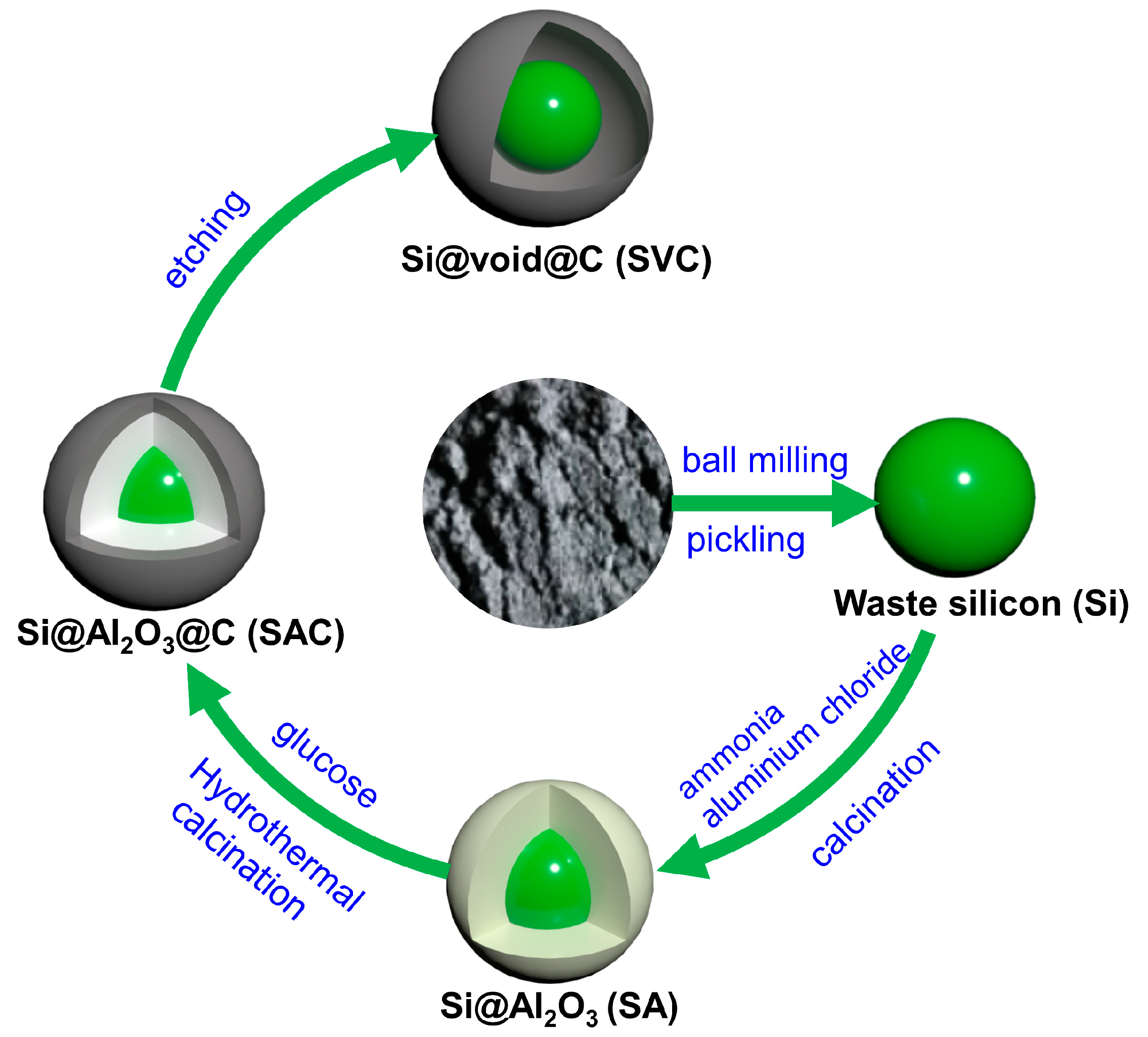
2.2. Synthesis of Si@void@C

The preparation process of the yolk–shell Si@void@C composite was illustrated as Figure 1. Firstly, a certain amount of AlCl3 was weighted and dissolved into 10 mL of deionized water in a beaker. Then, 10 mL of ammonia and 0.4 g of pretreated Si powder were added into the solution. After magnetic stirring with ultrasonication for 2 h, the mixture was collected by centrifugal drying. The dried mixture was calcined at 700 °C for 2 h with a horizontal tube furnace in an Ar atmosphere. Samples with an AlCl3/Si weight ratio of 2:1, 1:1, and 1:2 were named as SA−21, SA−11, and SA−12, respectively.
Secondly, 0.4 g of SA−21, SA−11, or SA−12 were weighted into a beaker containing 25 mL of deionized water. Then, 1.2 g of glucose monohydrate were added to the above solution, followed by magnetic stirring with ultrasonication for 30 min. The precipitate was transferred into a Teflon–lined stainless steel autoclave and heated to 180 °C for 8 h. The resulting product was subsequently washed with deionized water, dried at 80 °C, and calcined for 2 h at 800 °C in an argon atmosphere. The obtained samples were named as SAC−21, SAC−11, and SAC−12, respectively.
Finally, SAC samples were pickled with a 4 mol/L hydrochloric acid solution for 24 h and then cleaned with deionized water 3 times. The obtained samples were named as SVC−21, SVC−11, and SVC−12, respectively.

2.3. Materials Characterization

The elemental content of KL Si waste before and after pretreatment is determined by an X-ray fluorescence spectrometer (XRF, ARL ADVANT’X IntelliPowerTM, Santa Clara, CA, USA). The morphologies of the samples were examined using scanning electron microscopy (SEM, JEOL JSM–7800F, Tokyo, Japan) and transmission electron microscopy (TEM, FEI Talos F200x G2, Waltham, MA, USA). Energy dispersive X-ray spectroscopy (EDS) analyzed the elemental distribution within the samples. X-ray diffraction (XRD, Bruker D8, Billerica, MA, USA) with Cu Kα radiation determined the crystalline structures of the products. X-ray photoelectron spectroscopy (XPS, Thermo Fisher K–Alpha Nexsa, USA) assessed the surface composition of the samples. The Raman system (DXR, Thermo Fisher, Waltham, MA, USA) with a 532 nm laser was used to prove the existence of Si and C and examine the structure of carbon. The carbon content is measured using the thermogravimetric analyzer (TG, NETZSCH STA449F3, Selb, Germany).

2.4. Electrochemical Measurements

The electrochemical performance of the Si@void@C material was assessed through the utilization of CR2032 half cells, wherein lithium foil served as both the counter and reference electrodes. The active material, the carbon black conductive agent, and the polyvinylidene fluoride binder were mixed and dissolved in N-methylpyrrolidone at a ratio of 8:1:1. The slurry was coated on the carbon–coated copper foil, followed by vacuum drying at 100 °C for 12 h. The mass loading of the electrodes was approximately 1.0 mg cm−2. The tested half–cells were then assembled in an argon–filled glovebox. Celgard 2400 was used as the separator, with 1.2 M LiPF6 in EC/DEC/EMC(1:1:1) + 10% FEC as the electrolyte.
Cyclic voltammetry (CV) was conducted at various scan rates; galvanostatic charge–discharge (GCD) cycling was performed at various current densities, and electrochemical impedance spectroscopy (EIS) was measured over a frequency range of 100 kHz to 0.01 Hz using an Ivium–n–Stat Electrochemical Workstation. Charge/discharge tests were performed on a Neware BTS–5V10 mA battery test system under different current densities between 0.01–1.2 V.

3. Results

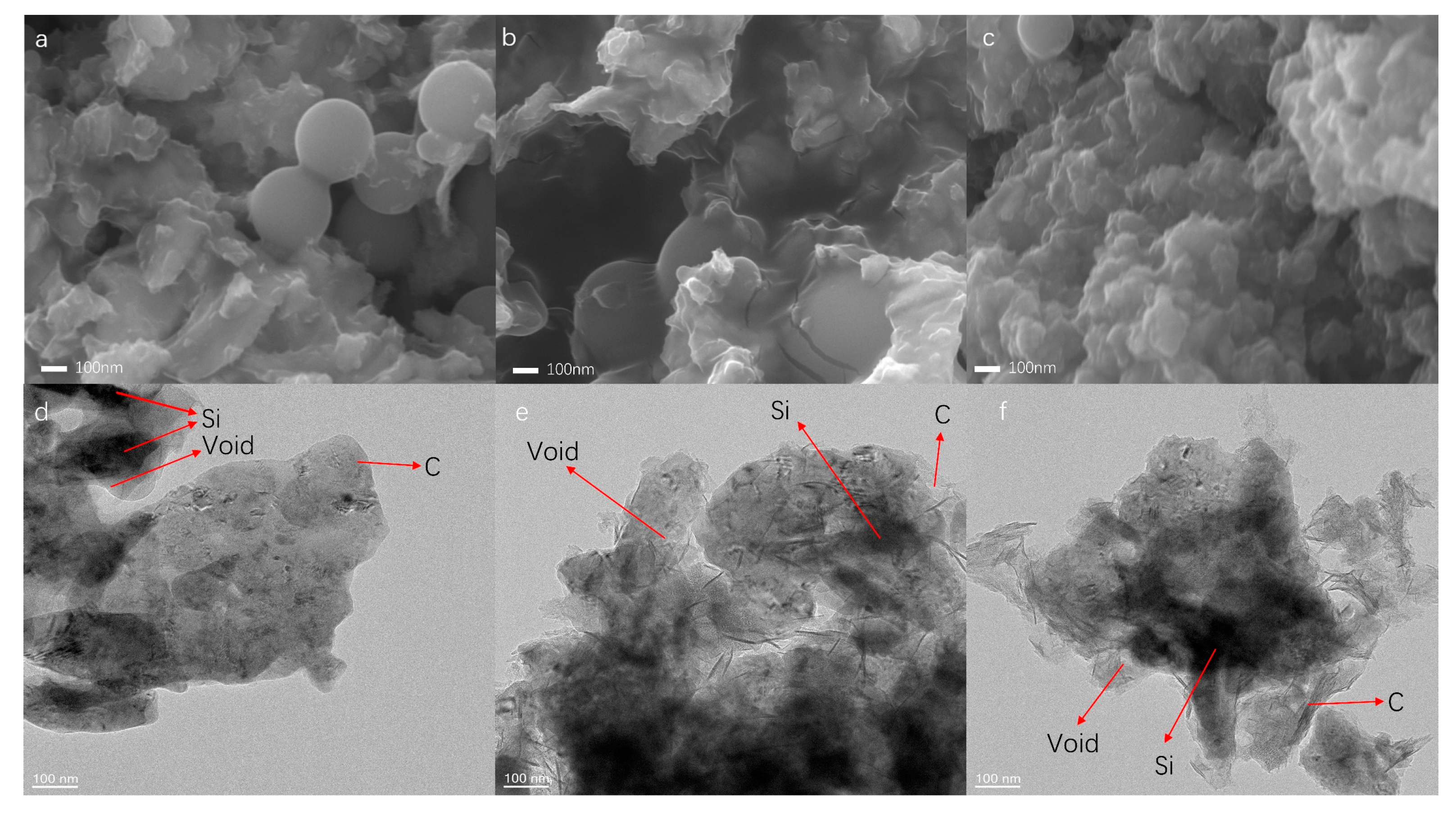
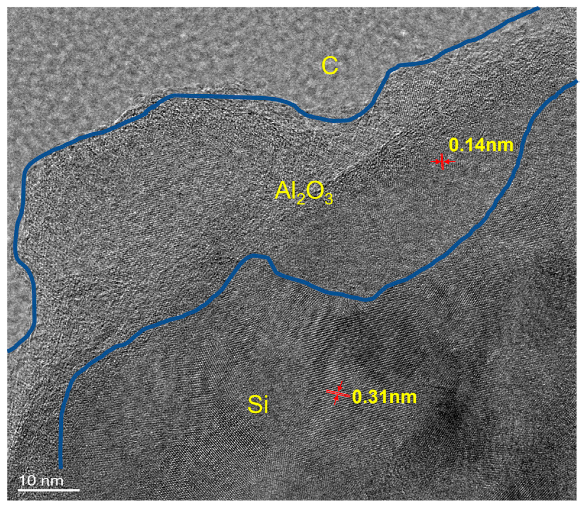
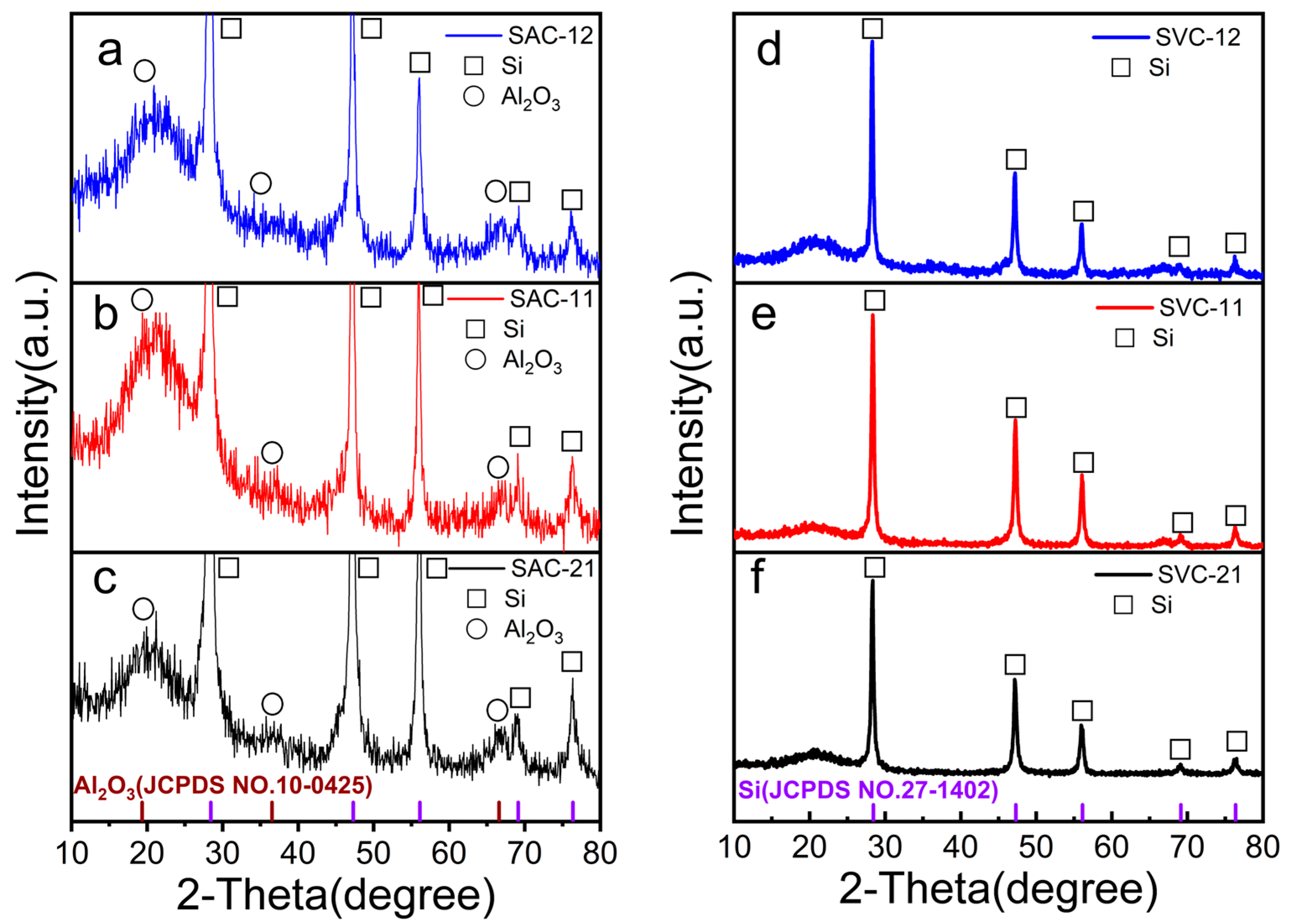
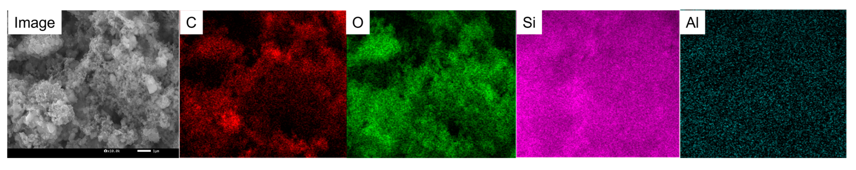
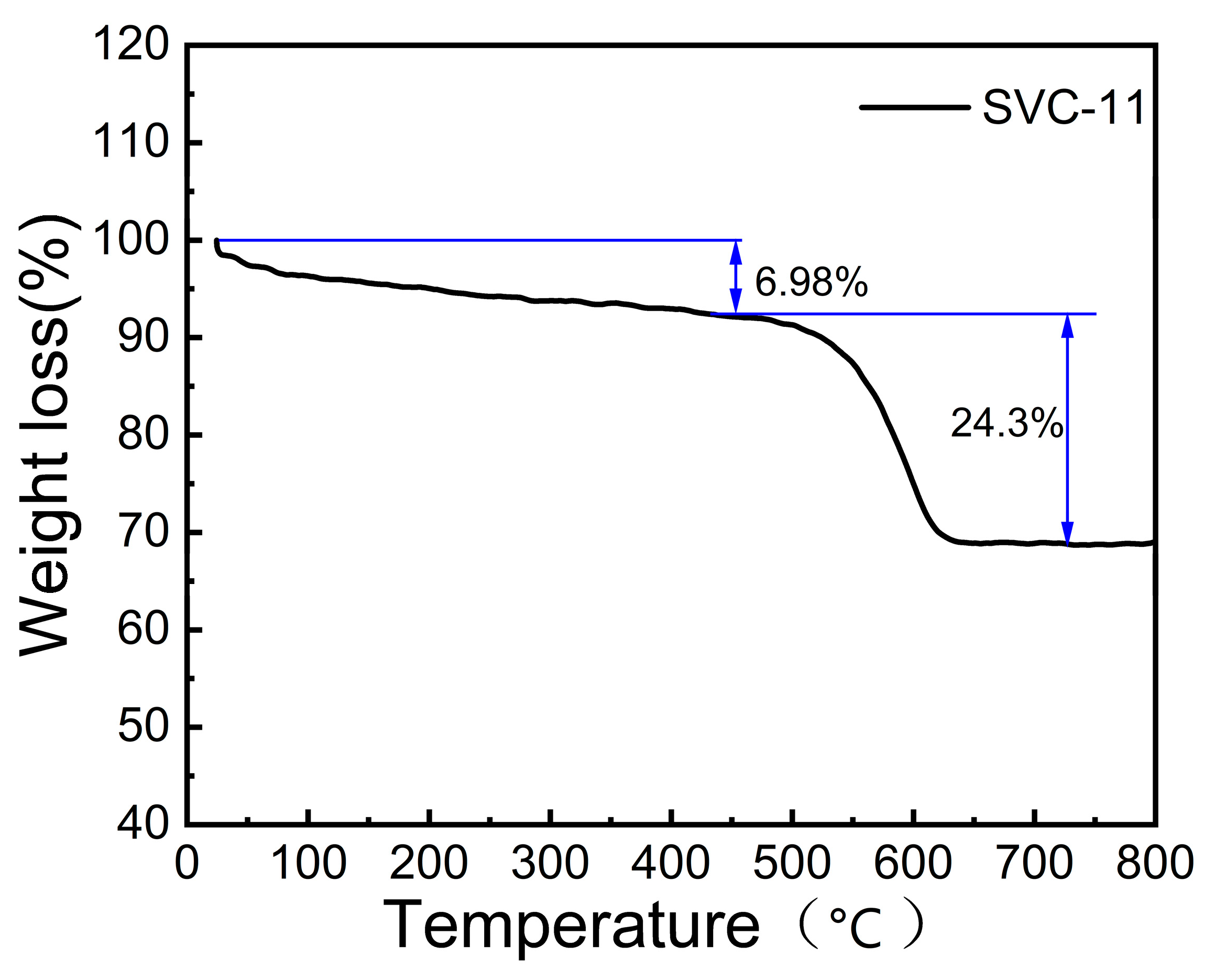
3.1. Material Morphology, Structure, and Chemical Composition

Table 1 presents the elemental compositions of KL Si waste and pretreated Si powder determined by XRF. The KL Si waste contains a significant amount of impurities due to the inevitable introduction of impurities during the cutting process, mainly from damaged diamond–wire, such as Fe, Cr, Zr, and Ni. After the pretreatment process, the content of impurities in Si powder has been significantly reduced, a result attributed to acid pickling.
The SEM images of SVC−21, SVC−11, and SVC−12 are shown in Figure 2a–c, respectively. All three samples contain sheet–like structures mixed with uneven spheres. The spherical structures are due to the decomposition of glucose into soluble molecules such as aromatic compounds, organic acids, and oligosaccharides in the hydrothermal reaction. After polymerization and aromatization, these molecules will diffuse around with a particle as the core to grow carbon spheres [24]. The addition of metal ions (Al3+) in the hydrothermal process will accelerate the polymerization process and promote the formation of spherical structures [25]. EDS mapping results of SAC−21, SAC−11, and SAC−12, shown in Figure 3a–c, respectively, indicate that the sheet–like structure mainly contains C and Si, and the spherical structures mainly contain C. The uniformly distributed Al and O indicate that a layer of Al2O3 was synthesized, which is also proved by the TEM image of SAC−11, shown in Figure 4. The amorphous layer without lattice fringes in the HRTEM image was believed to be a carbon shell, as carbon is in the amorphous phase, proven by XRD patterns in Figure 5 and previous studies [7,8]. The crystalline layer with a lattice fringe spacing of 0.31 nm corresponds to the (111) plane of Si, while the intermediate crystalline layer with a lattice fringe distance of 0.14 nm corresponds to the (440) plane of Al2O3.
Figure 2d–f presents the TEM images of SVC−21, SVC−11, and SVC−12, respectively. In all samples, Si particles are enveloped by an amorphous carbon shell with a void space between the Si core and the carbon shell. This structural arrangement facilitates excellent dispersion and effectively prevents the aggregation of Si particles.
The SAC samples exhibit the (111), (220), (311), (400), and (331) crystal planes of silicon at 28°, 47°, 56°, 69°, and 76° positions [26], respectively. Additionally, the SAC samples show the (111), (311), and (400) crystal planes of Al2O3 at 19.6°, 37.6°, and 66.7° positions [27]. SAC samples exhibit a mixture phase of Si and Al2O3, which is consistent with the EDS mapping results shown in Figure 3. Of note is that Al2O3 peaks increased significantly with the increase of the AlCl3/Si weight ratio during the synthesis of SAC. In contrast, only the crystal planes of silicon are apparent in the XRD pattern of the SVC sample, and the phase of Al2O3 is not clearly displayed, indicating that the etching process effectively removes the Al2O3. This is also illustrated by the EDS mapping result of SVC−11 as shown in Figure 6. Compared with the EDS mapping result of the SAC material, the content of the Al element in the SVC material is significantly decreased, thus proving that the etching process effectively removes aluminum. As the carbon in the SVC sample is in the amorphous phase, no carbon peak is detected [28].
X-ray photoelectron spectroscopy (XPS) was performed to examine the elemental composition of SVC−11, as depicted in Figure 7. The obtained XPS spectrum exhibits prominent peaks corresponding to C 1s, Si 2p, Si 2s, O 1s, and Al 2p (Figure 7a), confirming the presence of Si, C, O, and Al [29,30]. The presence of Al can be attributed to the residual Al2O3 resulting from the acid pickling process of SAC−11. Moreover, the C 1s XPS spectrum provides insights into the binding configurations of oxygen and carbon in SVC−11 (Figure 7b). The deconvolution of the C 1s XPS spectrum reveals three distinct peaks representing the C–C bond (284.8 eV), the C–O bond (286.2 eV), and the C=O bond (288.8 eV) [31]. The Si 2p XPS spectra of SVC−11 is shown in Figure 7c, which is deconvoluted to three different peaks: the Si–Si bond (99.6eV), the Si–C bond (100.2 eV), and the Si–O bond (103.5 eV) [32]. The presence of C–C bonds indicates the existence of free carbon in the material, which is caused by the carbon layer generated during hydrothermal processes. The presence of Si–Si bonds confirms the existence of elemental silicon in the material. The appearance of Si–O bonds is due to the slight oxidation of the silicon surface during hydrothermal processes, while the Si–C bonds are produced during the hydrothermal process. The Si–C bond can provide a smooth transmission channel during ion desertion, ensuring the electroneutrality between the electrodes and enhancing the overall conductivity of the material. The Si–O bond indicates the slight oxidation of the silicon material surface, and this layer of oxide film can also alleviate the volume change in silicon to some extent, thereby enhancing its stability. Figure 7d presents the Raman spectra of SVC−11. Apart from the prominent Si peak observed at approximately 518 cm−1, the spectral analysis also reveals two distinctive peaks at 1350 cm−1 and 1590 cm−1, which correspond to the characteristic carbon vibrations. The former can be attributed to the presence of amorphous carbon materials, while the latter is associated with the vibration of sp2-bonded carbon atoms in graphite [33,34]. The ID/IG ratio of SVC−11 is approximately 0.88, suggesting a relatively elevated level of graphitization. This enhanced graphitization is advantageous as it contributes to the improvement of electrical conductivity within the carbon shell [35].
To further investigate and determine the content of fixed carbon in the SVC composite material, SVC−11 was subjected to TG testing, as shown in Figure 8. The test conditions consisted of heating the material in an air atmosphere from 25 °C to 800 °C at a rate of 10 °C/min. Figure 8 shows the thermogravimetric results of the material. It can be observed from the figure that the mass fraction of the SVC−11 sample decreased by 6.98% when the temperature reached 460 °C, which is caused by the volatilization of bound water and the oxidation of a small amount of carbon. After 460 °C, there was a significant decrease in the mass fraction of the material, indicating that the fixed carbon composition in the material had essentially diffused and disappeared in the form of CO2. The fixed carbon content of SVC−11 is approx. 24.3%, which is suitable for a Si-based anode; refer to previous literature [7,9].

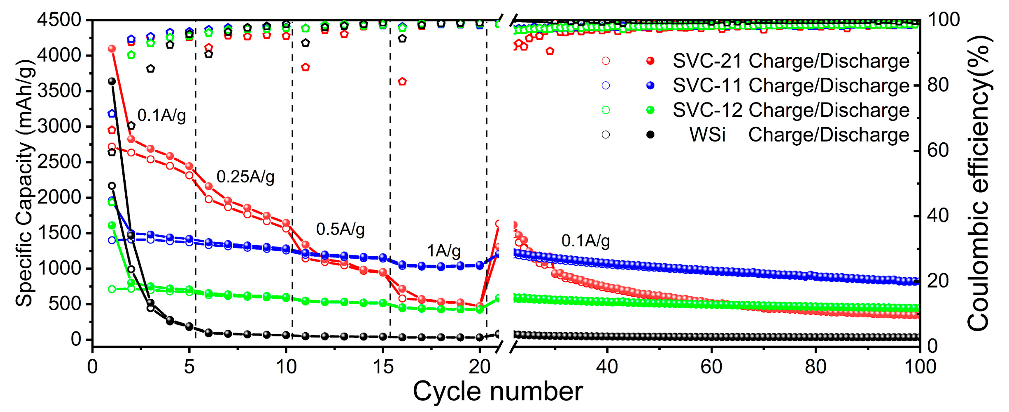
3.2. Electrochemical Performance of Si@void@C

The electrochemical performance of Si@void@C samples was evaluated in half–cell configurations. Figure 9a–c illustrates the cyclic voltammetry (CV) results obtained at a scan rate of 0.1 mV s−1 across a voltage range of 0.01–1.1 V. The CV curves of all three samples are similar. In the first discharge, the broad reduction peak at around 0.7 V corresponds to the irreversible reaction between Li+ ions and Si surface functional groups, as well as the solid electrolyte mesophase, which disappeared in subsequent cycles [36]. The reduction peak at 0.20 V corresponds to the formation of LixSi, while the oxidation peaks at 0.31 V and 0.49 V arise from LixSi and Si de-alloying, respectively [37,38]. SEI was generated after the discharge process and charging process in the first cycle, and more silicon was involved in the intercalation/deintercalation of the lithium–ion process, resulting in a decrease of the discharge current in subsequent cycles. In subsequent cycles, the current values of the two oxidation peaks increase notably, attributed to the activation of additional Si atoms in the material. Most notably, the CV curves nearly overlap after the second cycle, demonstrating that the anode material exhibits high reversibility.
Electrochemical impedance spectroscopy (EIS) was performed to investigate the variations in electrical conductivity and ion diffusion of the fresh electrode. The EIS diagram of the three materials was fitted into the standard equivalent circuit inside the diagram, which was composed of the solution resistor Rs from the reference electrode to the working electrode, the Constant Phase Angle Element Cpe in parallel with the charge transfer resistor Rct, and the Warburg resistor Wop for solid phase diffusion in series. The EIS test conditions for the three materials were tested in the frequency range of 100 kHz to 0.01 Hz, and the AC perturbation amplitude was 10 mV. The Nyquist plots of fresh SVC−21, SVC−11, and SVC−12 electrodes are presented in Figure 9d–f, respectively. A single semicircle was evident in the high–frequency region of all three Nyquist plots, attributed to charge transfer resistance (Rct) at the interface between the active materials and the electrolyte. A linear response appeared in the low–frequency region, indicative of Warburg diffusion impedance [39]. The electrode material tends to be a capacitor with the slope of a straight line close to 90°. The Bode plots of the three materials are provided in Figure 10. It can be seen from the Bode plot that the material presents a curve close to the X-axis at a frequency between 1–1000 Hz. According to the theoretical impedance module, there is a line with a slope of 1 in the Bode plot [40], but the slope of the tested material is much higher than 1, which also indicates that the material is controlled by the capacitor’s behavior. The charge transfer resistance (Rct) of SVC−21, SVC−11, and SVC−12 is 176, 65, and 87 Ω, respectively. The Rct value of SVC−11 is obviously lower than that of SVC−21 and SVC−12, which indicates the enhanced charge transfer kinetics of SVC−11 [41].
Galvanostatic charge–discharge (GCD) measurements were conducted on Si@void@C electrodes under a consistent current density of 0.1 A g−1 across a voltage range spanning from 0.01 V to 1.2 V, specifically for the initial three cycles. For comparison, an electrode using nanoscale waste Si (WSi) after pretreatment was also prepared and evaluated under the same conditions as described above. As shown in Figure 11a–c, the initial charge/discharge capacities of SVC−21, SVC−11, and SVC−12 are 4097/2718, 1962/1400, and 1609/712 mAh g−1, giving the initial Coulomb efficiency of 66.3%, 71.4%, and 44.3%, respectively. According to the previous literature, the yolk–shell structure has a drawback that cannot be ignored, i.e., the central hollow layer reduces the contact point between the silicon core and the outer carbon layer. Experimental results show that SVC−11 has good electrochemical performance and low transfer resistance. This result is due to the suitable hollow layer thickness generated at an AlCl3/Si weight ratio of 1:1, which can effectively inhibit volume change and meanwhile also supplies sufficient contact sites between the silicon core and the outer carbon layer. Furthermore, the exceptional electrochemical reversibility of Si@void@C is further supported by the overlapping charge/discharge curves observed during the second and third cycles. In contrast, the charge/discharge curves of WSi exhibit noticeable capacity loss and an increase in voltage hysteresis (Figure 11d). These results suggest that the amount of “dead lithium” can be effectively reduced, and the volumetric expansion of Si can be suppressed by forming the appropriate proportion of hollow layers and carbon layers.
Figure 12 presents the results of the long–term cycling performance of Si@void@C and WSi electrodes at different current densities (0.1, 0.25, 0.5, and 1 A g−1). During the testing, the SVC−11 electrode outperforms all other samples, demonstrating superior cycle performance by maintaining a discharge capacity of 836 mAh g−1 even after 100 cycles. SVC−21 and SVC−12 show relatively poor cycle performance with a discharge capacity of 345 and 446 mAh g−1 after 100 cycles, respectively, but still much higher than that of WSi (33.75 mAh g−1). These results suggest that the amount of “dead lithium” can be effectively reduced; the electronic conductivity can be increased; and the volumetric expansion of silicon can be suppressed by forming the appropriate proportion of hollow layers and carbon layers. The enhanced cycling performance of Si@void@C is attributable to its robust yolk–carbon shell architecture, which provides a void space to accommodate the considerable volume changes of Si during continuous lithiation and de-lithiation. This structure facilitates electron transfer and sustains the integrity of the solid electrolyte interface.
Table 2 provides a comparison between different anode materials and structures and this present work. Currently, the existing research mostly focuses on the doping of carbon surface elements and the improvement of the preparation method for yolk–shell structures. It is true that the doped carbon layer with surface elements has significant improvement in capacity. However, the materials that can be used for element doping are expansive, and the synthesis method is not economical. This present work did not use an element doping treatment on the carbon surface. A hydrothermal carbonization method was used to stabilize the carbon coating layer at a low cost. Moreover, the synthesized Si@void@C anode materials in the present work also present good electrochemical performance with a cheap Si source from industrial waste and simple processes. The intermediate sacrificial layer was prepared through a high–temperature dehydration process after the reaction of ammonia water and aluminum chloride, while the carbon layer was synthesized via the hydrothermal method, with the advantage of simplicity and controllability in the fabrication process. The proposed approach effectively utilizes the Si resources; it also helps to reduce environmental pollution caused by abandoned Si waste.

4. Conclusions

The yolk–shell Si@void@C with an intermediate hollow layer is fabricated using KL Si waste as the Si source. The intermediate sacrificial layer is generated by a metathesis reaction from AlCl3 and ammonia, and the outer carbon shell is generated by a hydrothermal process with glucose. Finally, the hollow layer is obtained by etching the intermediate sacrificial layer. After testing, SVC−11 showed significantly enhanced reversible capacity and cyclic stability (~836 mAh g−1 after 100 cycles at 0.1 A g−1). This scheme uses KL silicon waste as a silicon source. On the one hand, it makes full use of this part of abandoned resources to enhance the value of materials. On the other hand, such effective resource utilization avoids environmental pollution. An aluminum layer is prepared by the double decomposition reaction of aluminum chloride and ammonia water. The method is simple and controllable. Carbon coating uses cheap glucose and uses a hydrothermal method for operation; the hydrothermal method is relatively simple, and carbon coating is also relatively stable. Overall, the method provides a preparation solution for the yolk–shell structure. The fabrication process involves simple methods and low cost raw materials, produces an anode suitable for practical applications, and also contributes to recover Si waste from the photovoltaic industry and reduce potentially negative environmental impacts.

Author Contributions

Conceptualization, H.J. and X.L.; formal analysis, H.J. and J.L.; investigation, H.J. and Z.Y.; methodology: Z.L. and X.L.; writing—original draft preparation, H.J. and Z.L.; writing—review and editing, X.L. and K.T.; supervision, X.L. and K.T.; project administration, X.L.; funding acquisition, X.L.; resources, K.T. All authors have read and agreed to the published version of the manuscript.

Funding

This research was supported by Department of Human Resources and Social Security of Jiangsu Province (Jiangsu Postdoctoral Research Funding Program, project No. 2021K180B), Taizhou Science and Technology Bureau (Technology Support Programme, project No. SSF20210131 and TS202202), and Jiangsu University (High–level Scientific Research Foundation for the introduction of talent, project No. 18JDG015).

Data Availability Statement

Data is contained within the article in the images and plots.

Conflicts of Interest

The authors declare no conflict of interest.

References

  1. Xu, Y.; Swaans, E.; Chen, S.; Basak, S.; Harks, P.P.R.; Peng, B.; Zandbergen, H.W.; Borsa, D.M.; Mulder, F.M. A high–performance Li–ion anode from direct deposition of Si nanoparticles. Nano Energy 2017, 38, 477–485. [Google Scholar] [CrossRef]
  2. Zhong, Y.; Wu, P.; Ge, S.; Wu, Y.; Shi, B.; Shao, G.; Gu, C.; Su, Z.; Liu, A. An egg holders–inspired structure design for large–volume–change anodes with long cycle life. J. Alloys Compd. 2020, 816, 152497. [Google Scholar] [CrossRef]
  3. Zhang, C.; Yang, J.; Mi, H.; Li, Y.; Zhang, P.; Zhang, H. A carob–inspired nanoscale design of yolk–shell Si@void@TiO2–CNF composite as anode material for high–performance lithium–ion batteries. Dalton Trans. 2019, 48, 6846–6852. [Google Scholar] [CrossRef] [PubMed]
  4. Ji, H.; Luo, T.; Dai, L.; He, Z.; Wang, Q. Topology design of cold plates for pouch battery thermal management considering heat distribution characteristics. Appl. Therm. Eng. 2023, 224, 119940. [Google Scholar] [CrossRef]
  5. Gu, Y.; Jiao, Z.; Wu, M.; Luo, B.; Lei, Y.; Wang, Y.; Wang, L.; Zhang, H. Construction of point–line–plane (0–1–2 dimensional) Fe2O3–SnO2/graphene hybrids as the anodes with excellent lithium storage capability. Nano Res. 2017, 10, 121–133. [Google Scholar] [CrossRef]
  6. Lee, J.I.; Song, G.; Cho, S.; Han, D.Y.; Park, S. Lithium metal interface modification for high–energy batteries: Approaches and characterization. Batter. Supercaps 2020, 3, 828–859. [Google Scholar] [CrossRef]
  7. Ji, H.; Li, J.; Li, S.; Cui, Y.; Liu, Z.; Huang, M.; Xu, C.; Li, G.; Zhao, Y.; Li, H. High–Value Utilization of Silicon Cutting Waste and Excrementum Bombycis to Synthesize Silicon–Carbon Composites as Anode Materials for Li–Ion Batteries. Nanomaterials 2022, 12, 2875. [Google Scholar] [CrossRef]
  8. Ji, H.; Luo, T.; Dai, L.; He, Z.; Wang, Q. Numerical investigation on the polarization and thermal characteristics of LiFePO4-based batteries during charging process. Appl. Therm. Eng. 2022, 214, 118709. [Google Scholar] [CrossRef]
  9. Pan, L.; Wang, H.; Gao, D.; Chen, S.; Tan, L.; Li, L. Facile synthesis of yolk–shell structured Si–C nanocomposites as anodes for lithium–ion batteries. Chem. Commun. 2014, 50, 5878–5880. [Google Scholar] [CrossRef] [Green Version]
  10. Ru, Y.; Evans, D.G.; Zhu, H.; Yang, W. Facile fabrication of yolk–shell structured porous Si–C microspheres as effective anode materials for Li–ion batteries. RSC Adv. 2014, 4, 71–75. [Google Scholar] [CrossRef]
  11. Sun, Z.; Song, X.; Zhang, P.; Gao, L. Controlled synthesis of yolk–mesoporous shell Si@SiO2 nanohybrid designed for high performance Li ion battery. RSC Adv. 2014, 4, 20814–20820. [Google Scholar] [CrossRef]
  12. Sun, Z.; Tao, S.; Song, X.; Zhang, P.; Gao, L. A silicon/double–shelled carbon yolk–like nanostructure as high–performance anode materials for lithium–ion battery. J. Electrochem. Soc. 2015, 162, A1530. [Google Scholar] [CrossRef]
  13. Li, J.; Lin, Y.; Shi, J.; Ban, B.; Sun, J.; Ma, Y.; Wang, F.; Lv, W.; Chen, J. Recovery of high purity Si from kerf–loss Si slurry waste by flotation method using PEA collector. Waste Manag. 2020, 115, 1–7. [Google Scholar] [CrossRef] [PubMed]
  14. Yang, H.; Liu, I.; Liu, C.; Hsu, H.; Lan, C. Recycling and reuse of kerf–loss silicon from diamond wire sawing for photovoltaic industry. Waste Manag. 2019, 84, 204–210. [Google Scholar] [CrossRef] [PubMed]
  15. Li, J.; Lin, Y.; Wang, F.; Shi, J.; Sun, J.; Ban, B.; Liu, G.; Chen, J. Progress in recovery and recycling of kerf loss silicon waste in photovoltaic industry. Sep. Purif. Technol. 2021, 254, 117581. [Google Scholar] [CrossRef]
  16. Drouiche, N.; Cuellar, P.; Kerkar, F.; Medjahed, S.; Boutouchent-Guerfi, N.; Hamou, M.O. Recovery of solar grade silicon from kerf loss slurry waste. Renew. Sustain. Energy Rev. 2014, 32, 936–943. [Google Scholar] [CrossRef]
  17. Xiang, K.; Wang, X.; Chen, M.; Shen, Y.; Shu, H.; Yang, X. Industrial waste silica preparation of silicon carbide composites and their applications in lithium–ion battery anode. J. Alloys Compd. 2017, 695, 100–105. [Google Scholar] [CrossRef]
  18. Liu, W.; Liu, J.; Zhu, M.; Wang, W.; Wang, L.; Xie, S.; Wang, L.; Yang, X.; He, X.; Sun, Y. Recycling of lignin and Si waste for advanced Si/C battery anodes. ACS Appl. Mater. Interfaces 2020, 12, 57055–57063. [Google Scholar] [CrossRef]
  19. Li, H.; Wang, J.; Wu, X.; Sun, H.; Yang, F.; Wang, K.; Zhang, L.; Fan, C.; Zhang, J. A novel approach to prepare Si/C nanocomposites with yolk–shell structures for lithium ion batteries. RSC Adv. 2014, 4, 36218–36225. [Google Scholar] [CrossRef]
  20. Zhang, L.; Rajagopalan, R.; Guo, H.; Hu, X.; Dou, S.; Liu, H. A Green and Facile way to prepare Granadilla–like silicon-based anode materials for Li–ion batteries. Adv. Funct. Mater. 2016, 26, 440–446. [Google Scholar] [CrossRef] [Green Version]
  21. Yang, T.; Gao, Y.; Tang, Y.; Zhang, Y.; Li, X.; Liu, L. Porous silicon from industrial waste engineered for superior stability lithium–ion battery anodes. J. Nanopart. Res. 2021, 23, 209. [Google Scholar] [CrossRef]
  22. Zhang, J.; Li, S.; Xi, F.; Wan, X.; Ding, Z.; Chen, Z.; Ma, W.; Deng, R. Si@SiOx/Ag composite anodes with high initial coulombic efficiency derive from recyclable silicon cutting waste. Chem. Eng. J. 2022, 447, 137563. [Google Scholar] [CrossRef]
  23. Gao, Y.; Qiu, X.; Wang, X.; Gu, A.; Chen, X.; Yu, Z. Facile preparation of nitrogen–doped yolk–shell Si@void@C/CNTs microspheres as high–performance anode in lithium–ion batteries. Mater. Today Commun. 2020, 25, 101589. [Google Scholar] [CrossRef]
  24. Guan, H.; Wang, Q.; Wu, X.; Pang, J.; Jiang, Z.; Chen, G.; Dong, C.; Wang, L.; Gong, C. Biomass derived porous carbon (BPC) and their composites as lightweight and efficient microwave absorption materials. Compos. Part B Eng. 2021, 207, 108562. [Google Scholar] [CrossRef]
  25. Yang, H.; Wang, G.; Ding, N.; Yin, C.; Chen, Y. Size–controllable synthesis of carbon spheres with assistance of metal ions. Synth. Met. 2016, 214, 1–4. [Google Scholar] [CrossRef]
  26. Hu, L.; Luo, B.; Wu, C.; Hu, P.; Wang, L.; Zhang, H. Yolk–shell Si/C composites with multiple Si nanoparticles encapsulated into double carbon shells as lithium–ion battery anodes. J. Energy Chem. 2019, 32, 124–130. [Google Scholar] [CrossRef]
  27. Xu, K.; Zhang, Z.; Su, W.; Wei, Z.; Zhong, G.; Wang, C.; Huang, X. Alumina coated nano silicon synthesized by aluminothermic reduction as anodes for lithium ion batteries. Funct. Mater. Lett. 2017, 10, 1650073. [Google Scholar] [CrossRef]
  28. Lu, Y.; Chang, P.; Wang, L.; Nzabahimana, J.; Hu, X. Yolk–shell Si/SiOx@Void@C composites as anode materials for lithium–ion batteries. Funct. Mater. Lett. 2019, 12, 1850094. [Google Scholar] [CrossRef] [Green Version]
  29. Wu, Y.; Han, T.; Zhou, T.; Qiao, X.; Chen, X.; Zhou, P.; Liu, J. A novel silicon nanoparticles–infilled capsule prepared by an oil–in–water emulsion strategy for high–performance Li–ion battery anodes. Nanotechnology 2020, 31, 335403. [Google Scholar] [CrossRef]
  30. Mi, H.; Yang, X.; Li, Y.; Zhang, P.; Sun, L. A self–sacrifice template strategy to fabricate yolk–shell structured silicon@void@ carbon composites for high–performance lithium–ion batteries. Chem. Eng. J. 2018, 351, 103–109. [Google Scholar] [CrossRef]
  31. Shao, T.; Liu, J.; Gan, L.; Gong, Z.; Long, M. Yolk–shell Si@void@C composite with Chito–oligosaccharide as a C–N precursor for high capacity anode in lithium–ion batteries. J. Phys. Chem. Solids 2021, 152, 109965. [Google Scholar] [CrossRef]
  32. Zhou, Z.; Pan, L.; Liu, Y.; Zhu, X.; Xie, X. From sand to fast and stable silicon anode: Synthesis of hollow Si@void@C yolk–shell microspheres by aluminothermic reduction for lithium storage. Chin. Chem. Lett. 2019, 30, 610–617. [Google Scholar] [CrossRef]
  33. Yoon, D.; Kim, D.H.; Chung, K.Y.; Chang, W.; Kim, S.M.; Kim, J. Hydrogen–enriched porous carbon nanosheets with high sodium storage capacity. Carbon 2016, 98, 213–220. [Google Scholar] [CrossRef]
  34. Zeng, S.; Chen, X.; Xu, R.; Wu, X.; Feng, Y.; Zhang, H.; Peng, S.; Yu, Y. Boosting the potassium storage performance of carbon anode via integration of adsorption–intercalation hybrid mechanisms. Nano Energy 2020, 73, 104807. [Google Scholar] [CrossRef]
  35. Ji, H.; Chen, Q.; Hua, K.; Ma, Q.; Wang, R.; Zhang, L.; Zhang, C. Si nanoparticles embedded in porous N-doped carbon fibers as a binder–free and flexible anode for high–performance lithium–ion batteries. J. Alloys Compd. 2023, 936, 168256. [Google Scholar] [CrossRef]
  36. Feng, Y.; Liu, L.; Liu, X.; Teng, Y.; Li, Y.; Guo, Y.; Zhu, Y.; Wang, X.; Chao, Y. Enabling the ability of Li storage at high rate as anodes by utilizing natural rice husks–based hierarchically porous SiO2/N–doped carbon composites. Electrochim. Acta 2020, 359, 136933. [Google Scholar] [CrossRef]
  37. Domi, Y.; Usui, H.; Shimizu, M.; Kakimoto, Y.; Sakaguchi, H. Effect of phosphorus–doping on electrochemical performance of silicon negative electrodes in lithium–ion batteries. ACS Appl. Mater. Interfaces 2016, 8, 7125–7132. [Google Scholar] [CrossRef]
  38. Liu, M.; Fan, H.; Zhuo, O.; Chen, J.; Hu, Z. A general strategy to construct yolk–shelled metal oxides inside carbon nanocages for high–stable lithium–ion battery anodes. Nano Energy 2019, 68, 104368. [Google Scholar] [CrossRef]
  39. Zhang, Y.C.; You, Y.; Xin, S.; Yin, Y.X.; Guo, Y.G. Rice Husk–Derived Hierarchical Silicon/Nitrogen–Doped Carbon/Carbon Nanotube Spheres as Low–Cost and High–Capacity Anodes for Lithium–Ion Batteries. Nano Energy 2016, 25, 120–127. [Google Scholar] [CrossRef]
  40. Xu, Y.; Wang, S.; Peng, H.; Yang, Z.; Martin, D.J.; Bund, A.; Nanjundan, A.K.; Yamauchi, Y. Electrochemical Characteristics of Cobaltosic Oxide in Organic Electrolyte According to Bode Plots: Double–Layer Capacitance and Pseudocapacitance. Chemelectrochem 2019, 6, 2456–2463. [Google Scholar] [CrossRef] [Green Version]
  41. Ji, H.; Tao, L.; Hu, B.; Xu, J.; Ding, J. Enhanced rate and low–temperature performance of LiFePO4 cathode with 2D Ti3C2 MXene as conductive network. Electroanal. Chem. 2023, 928, 117047. [Google Scholar] [CrossRef]
  42. Wu, C.Y.; Lin, T.Y.; Duh, J.G. Constructing cellulose nanofiber/Si composite 3D–Net structure from waste rice straw via freeze drying process for lithium–ion battery anode materials. Mater. Chem. Phys. 2022, 285, 126107. [Google Scholar] [CrossRef]
  43. Gao, J.; Zuo, S.; Liu, H.; Jiang, Q.; Wang, C.; Yin, H.; Wang, Z.; Wang, J. An interconnected and scalable hollow Si–C nanospheres/graphite composite for high–performance lithium–ion batteries. J. Colloid Interface Sci. 2022, 624, 555–563. [Google Scholar] [CrossRef] [PubMed]
  44. Zhang, W.; Li, J.; Guan, P.; Lv, C.; Yang, C.; Han, N.; Wang, X.; Song, G.; Peng, Z. One–pot sol–gel synthesis of Si/C yolk–shell anodes for high performance lithium–ion batteries. J. Alloys Compd. 2020, 835, 155135. [Google Scholar] [CrossRef]
  45. Wei, Y.; Huang, Y.; Zeng, Y.; Zhang, Y.; Cheng, W.; Wang, W.; Jia, D.; Tang, X.; Wang, L. Designed Formation of Yolk–Shell–Like N–Doped Carbon–Coated Si Nanoparticles by a Facile Method for Lithium–Ion Battery Anodes. ACS Appl. Energy Mater. 2022, 5, 1471–1477. [Google Scholar] [CrossRef]
Figure 1. Illustration of the Si@void@C composite preparation.
Processes 11 01764 g001
Figure 2. SEM image of (a) Si@void@C−21(SVC−21), (b) Si@void@C−11(SVC−11), (c) Si@void@C−12(SVC−12). Transmission Electron Microscope image of (d) Si@void@C−21(SVC−21), (e) Si@void@C−11(SVC−11), (f) Si@void@C−12(SVC−12).
Processes 11 01764 g002
Figure 3. EDS mapping results of (a) Si@Al2O3@C−21(SAC−21), (b) Si@Al2O3@C−11(SAC−11), (c) Si@Al2O3@C−12(SAC−12).
Processes 11 01764 g003
Figure 4. HRTEM image of Si@Al2O3@C−11(SAC−11).
Processes 11 01764 g004
Figure 5. XRD of (a) SAC−12, (b) SAC−11, (c) SAC−21; (d) SVC−12, (e) SVC−11, and (f) SVC−21.
Processes 11 01764 g005
Figure 6. EDS mapping results of Si@void@C−11(SVC−11).
Processes 11 01764 g006
Figure 7. XPS survey of SVC−11 (a); high resolution XPS spectra for (b) C 1s and (c) Si 2p; (d) Raman spectra of SVC−11.
Processes 11 01764 g007
Figure 8. Thermogravimetry analysis of SVC−11.
Processes 11 01764 g008
Figure 9. CV curves of SVC−21 (a), SVC−11 (b), and SVC−12 (c), showing the initial four cycles with a scanning speed of 0.1 mV s−1 at a voltage of 0.01–1.1 V; Nyquist plots of the fresh electrodes of SVC−21 (d), SVC−11 (e), and SVC−12 (f).
Processes 11 01764 g009
Figure 10. Bode plots of SVC−21, SVC−11, and SVC−12. The solid circle line represents the amplitude-frequency characteristic curve, and the hollow circle line represents the hase-frequency characteristic curve.
Processes 11 01764 g010
Figure 11. GCD curves at 0.1 A g−1 of SVC−21 (a), SVC−11 (b), SVC−12 (c), and WSi (d).
Processes 11 01764 g011
Figure 12. Rate and cycling performance of WSi, SVC−21, SVC−11, and SVC−12.
Processes 11 01764 g012
Table 1. The elemental compositions of KL Si waste and pretreated Si powder, wt%.
ElementSiFeCrZrNiCaMgCu
KL Si89.945.331.281.210.660.0480.0420.032
pretreated Si98.560.0096/0.0240.0200.0090//
Table 2. Comparison of the specific capacity of silicon carbon anode materials.
No. MaterialMethodSpecific CapacitanceReference
1Si–CNF2freeze drying640 mAh g−1 at 0.5 A g−1 after 100 cycles [42]
2Si/Cmagnesiothermic reduction reaction662 mAh g−1 at 0.5 A g−1 after 200 cycles [43]
3Si@HCone–pot sol–gel approach999.5 mAh g−1 at 0.1 A g−1 after 100 cycles [44]
4Si@void@Chydrothermal method1038.5 mAh g−1 at 0.42 A g−1 after 200 cycles[31]
5Si@void@NCsolution coating and calcination process697.7 mAh g−1 at 0.2 A g−1 after 200 cycles [45]
6SVC−11metathesis reaction836 mAh g−1 at 0.1 A g−1 after 100 cycles present work
Disclaimer/Publisher’s Note: The statements, opinions and data contained in all publications are solely those of the individual author(s) and contributor(s) and not of MDPI and/or the editor(s). MDPI and/or the editor(s) disclaim responsibility for any injury to people or property resulting from any ideas, methods, instructions or products referred to in the content.

