Article

CFD Investigation on the Performance of Cyclone Separators with Divergent or Convergent Insertion Pipes

1
School of Mechanical Engineering, Yangtze University, Jingzhou 434023, China
2
Engineering & Design Institute of CPOE, Beijing 100028, China
3
School of Mechanical Engineering, Chongqing University of Technology, Chongqing 400054, China
*
Author to whom correspondence should be addressed.
Processes 2023, 11(7), 2061; https://doi.org/10.3390/pr11072061
Submission received: 30 May 2023 / Revised: 1 July 2023 / Accepted: 7 July 2023 / Published: 10 July 2023

Abstract

:
For multi-phase separation, developing high-performance cyclone separators is highly demanded. In this study, different divergent or convergent insertion pipes bFelow the vortex finder are employed to improve the separation performance. The impacts of insertion pipe geometrical configurations on the flow characteristics, pressure drop, and separation efficiency are systematically analyzed. The results reveal that the employed insertion pipe can significantly affect the static pressure distribution inside the cyclone. A longer insertion pipe length and larger tilt angle result in a wider central low-pressure area and smaller overall static pressure. The divergent insertion pipes increase pressure loss, while the convergent insertion pipes augment pressure loss. A larger insertion pipe length significantly impacts the axial velocity distribution. For divergent insertion pipes, the maximum central axial velocity increases with increasing tilt angles and then decreases. For small particles (dp ≤ 5 μm), a convergent insertion pipe exhibits a better separation performance. When the particle diameter dp ≥ 5 μm, divergent insertion pipes with larger angles and lengths can significantly decrease the pressure drop while guaranteeing satisfied collection efficiency. When L = 75 mm and θ = 60°, the pressure drop is reduced by 7.8%. This study may contribute to rationally designing high performance cyclone separators and also paves ways for improving the existing cyclone separators.

1. Introduction

With a simple structure and low maintenance cost, cyclone separators are widely applied in industrial two-phase/multi-phase separations such as liquid–gas separation in the natural gas exploitation process [1,2] and solid–liquid separation in the fluidized bed coal combustion [3,4]. Multi-phase separation is achieved by the centrifugal force [5,6]. In cyclone separators, the rotating turbulence field inside the cyclone is rather complex [7,8]. Simulations based on Reynolds stress and large eddy models were shown to accurately simulate the flow characteristics in the cyclone separators [9,10,11,12,13,14]. Compared to the large eddy models and direct numerical simulation(DNS), the Reynolds stress presents less demand on computational resources and satisfied accuracy, which is widely employed to numerically describe the complex flow characteristics inside the cyclone separators [15]. However, the Reynolds stress model can only provide the average information concerning the turbulence and cannot simulate too complex vortex motion. Griffiths [16] concludes that the RNG k-ε model can better describe the anisotropy of the turbulent field characteristics using a comparative analysis with experiments. Dang et al. [17] proposed a new method to simulate cyclone separators that can simultaneously decrease computational time and enhance accuracy for CFD simulations.
For cyclone separators, pressure loss, as well as separation efficiency, are the main performance indicators that should be addressed [18,19,20]. Much attention was drawn to augment their performance. The inlet size is one of the important factors affecting its performance [21,22,23]. Elsayed et al. [24] studied different cyclone separators of various inlet sizes, revealing that the larger inlet size of the cyclone separator contributes to the reduction in the pressure drop. The inlet width presented a much more dominant impact than the inlet height. Horvath et al. [25] simulated the axial velocity variation under different geometric configurations. Qian et al. [26] investigated different inlet cross-section types and pinch angles. The pressure drop was minimized when the inlet cross-section angle was 45°. Tan et al. [27] revealed that the larger particle diameter contributes to the separator via experiments and numerical simulations, respectively. However, Liu [28] et al. claimed that there exists a critical diameter, leading to the maximum separator efficiency. Ehsan et al. [29] found that the baffles have a major effect on improving the separation efficiency and turbulence intensity. In addition, Ehsan et al. [30] also studied the effect of the number of inlets and the cyclone cone wall roughness on the swirling flow characteristics and separation efficiency of the cyclone.
The cylinder and the vertebrae are also important components of the cyclone separators, and their length, diameter, angle, and other geometric dimensions act dominantly in determining the pressure drop and separation efficiency [31]. Lee et al. [32] revealed how the cylinder diameter impacts the particle collection efficiencies and flow characteristics. Brar et al. [33] revealed that a vertebral length of approximately 6.5 times its diameter can significantly augment the separation efficiency. Demir et al. [34] revealed that the friction loss is low at a small vertebral height. Hamdy et al. [35] investigated the impacts of vertebral length, showing that increasing the vertebral length could increase the back flow below the vortex finder. Gimbun et al. [36] and Elsayed et al. [37,38] found that changes in the dust discharge port diameter significantly altered separator performance. Satyanand et al. [39] evaluated the effect of various geometrical shapes of the conical segment on cyclone performance, and they predicted the performance of different models using the Reynolds stress model considering two pressure-strain options.
The vortex finder also impacts cyclone separator performance [40,41]. El-Batsh [42] revealed that cyclone separator performance is mainly impacted by the finder diameter rather than the finder length. Tan et al. [43] found that satisfied separation efficiency could be achieved when the vortex finder diameter was controlled at 0.3–0.5 D where D is the cylinder diameter. Hoekstra [44] concluded that the maximum tangential velocity and pressure drop gradually decrease with increasing finder diameters. In addition, Hugi et al. [45] revealed that under some situations of particle size distributions, employing vortex finders is unnecessary.
Although performance improvement and optimization of the cyclone separator were extensively studied in the previous literature, the separation performance of ultra-fine particles is still far from satisfied. Since the escape of particles is through the vortex finder at the upper end of the cyclone, optimizing the vortex detector can greatly improve the separation performance of the separator. In this study, unlike the optimized vortex detector shapes in previous studies, different divergent or convergent insertion pipes below the vortex finder were constructed to improve the internal flow characteristics and, thus, increase the separation efficiency. The Reynolds stress turbulence model is employed to describe the rotating turbulence field inside the cyclone. The pulsation velocity in all the flow directions has a significant impact on the movement velocity of small particles. To fully grasp the influence of these factors on the turbulence and pulsation velocity, the discrete random walk (DRW) is applied for particle tracking [46,47]. The impacts of different divergent or convergent insertion pipes on the flow field characteristics, separation performance, and pressure loss were systematically analyzed. The undermining mechanisms are discussed. Finally, some useful conclusions are drawn. This study may contribute to rationally designing high performance cyclone separators and also pave the way for improving the existing cyclone separators.

2. Model Description

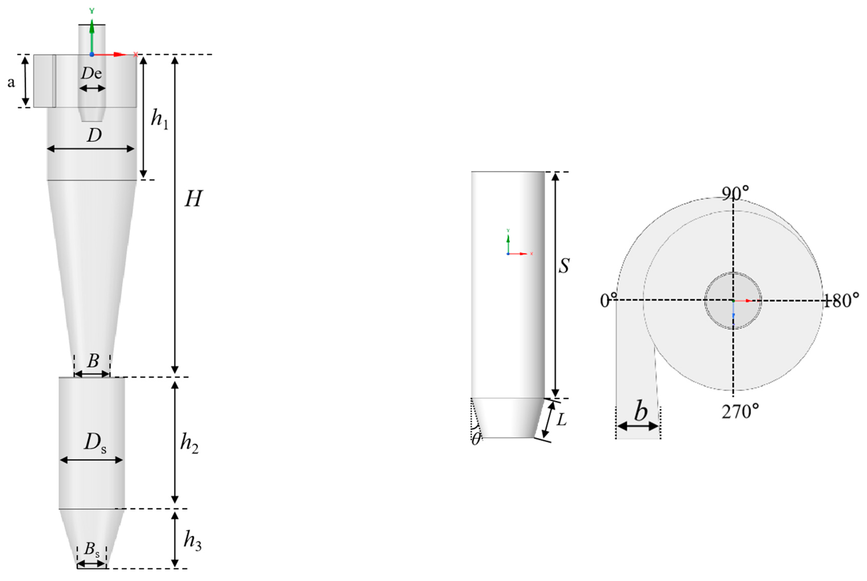
2.1. Geometrical Characteristics

As depicted in Figure 1, the reverse-flow cyclone with a volute inlet is employed for the numerical simulation. The sizes of the cyclone separator are based on Ref. [15]. The relevant modeling parameters of the studied cyclone separator are presented in Table 1. Different divergent or convergent insertion pipes are attached below the vortex finder. The divergent or convergent insertion pipes are characterized by the angle (θ) and length (L). The length L is set at 25, 50, and 75 mm, respectively; and the angle θ varies from −30 to 60°. θ = 0° or L = 0 mm in the study refers to the original configuration without installation of the insertion pipes, as shown in Figure 2b. θ > 0° indicates the insertion pipe is divergent; θ < 0° represents that the insertion pipe is convergent. Figure 2a,c show the shape of the insertion pipes with θ = 30° and −15° at the length L = 50 mm, respectively.

2.2. Computational Fluid Dynamics Model

2.2.1. Reynolds Stress Model

Although the simulation accuracy of a large eddy simulation is better, it requires too many computational resources. Considering the simulation computational cost and the accuracy of the simulation, the Reynolds stress model (RSM) is employed in the simulation. The SIMPLE algorithm is used for dealing with the pressure–velocity coupling; the PRESTO scheme is employed for dealing with the pressure gradient; and the QUICK differential format is applied to handle the other physical items [15].
The time-averaged conservation equations are applied to describe the rotating turbulence field inside the cyclone separator [48]:
u i ¯ x j = 0
ρ u i ¯ u i ¯ x j = P ¯ x i + x j [ μ ( u i ¯ x j + u j ¯ x i ) ] ρ u i u j ¯ x j
where u i ¯ and u j ¯ are the mean velocities; ρ u i u j ¯ is the Reynolds stress caused by turbulent pulsations.
The RSM model is a turbulence model based on each anisotropy, without using Boussinesq’s assumptions, that is suitable for solving strong cyclonic flows inside the cyclone separator.
t ( ρ u i u j ¯   ) + x k ( ρ u k u i u j ¯   ) = D T , i j + D L , i j + P i j + G i j + i j F i j ε i j + S u s e r
where D T , i j represents the diffusive transport term, which is calculated as:
D T , i j = x k ( ρ u i u j u k ¯ + P ( σ j k u k + σ i k u j ) ¯   )
The term D L , i j in Equation (3) represents the molecular viscous diffusion term, which is given by:
D L , i j = μ x k u i u j ¯
Stress P i j is given by:
P i j = ρ ( u i u k ¯ u j x k + u j u k ¯ u i x k )
The term G i j represents the buoyancy generation term:
G i j = ρ β [ g i ( u j θ ) + g j ( u i θ ) ]
The pressure strain correlation i j is given by:
i j = P ( u i x j + u j x i ) ¯
The system rotation generation term F i j is:
F i j = 2 ρ Ω k ( u j u j ε i k m + u i u m ε j k m )
The dissipative ε i j is:
ε i j = 2 μ u i x k u j x k ) ¯
The near-wall velocity is calculated by [49]:
U C μ 1 / 4 k 1 / 2 τ w / ρ = 1 κ ln ( E y * )
y * = ρ C μ 1 / 4 k 1 / 2 y μ
The relevant parameters can be seen in Refs. [44,50].

2.2.2. Discrete Phase Model

Due to the low concentration of particles in this simulation, the discrete phase model (DPM) is applied in the present simulation. Due to the small particle diameter and the pulsating velocity of the gas flow in all directions, this can have a direct effect on the particle motion. Considering the effect of gas turbulence and pulsation velocity on particle motion, the discrete random walk model was chosen to track the particles. The model equations used are summarized as follows:
Tee equations for mass and momentum conservation of the gas phase are given by:
( ρ g ε g ) t + · ( ρ g ε g u g ) = 0
( ρ g ε g u g ) t + · ( ρ g ε g u g u g ) = P + μ ε g 2 u g + ρ g ε g g S
S = F D V
m p d u p d t = m p u u p τ r + m p g ( ρ p ρ ) ρ p + F
where F is the sum of the particle swaying forces acting inside the grid cell. m p is the particle mass; τ r is the particle residence time, which is given by:
τ r = ρ p d p 2 18 u 24 C d R e

2.3. Boundary Conditions

The inlet gas is methane at room temperature and pressure. The velocity inlet of 15 m/s is employed. The hydraulic diameter and turbulence intensity at the inlet are calculated from Equations (18) and (19).
D H = 4 × S C
I = 0.16 × ( ρ g D H V i n μ ) 0.125
where S is the flow cross-sectional area; C is the inlet wetted perimeter; ρ g is the inlet gas density; μ is the inlet gas viscosity; D H is the hydraulic diameter; and I is the turbulence intensity.
The exit boundary condition is set to outflow and the inlet to velocity boundary condition. A no-slip boundary is employed on other boundaries. In the calculation, a steady-state simulation is used first, followed by transient simulation to obtain a stable flow field, thus, reducing the convergence difficulty and improving the accuracy. When performing the DPM iteration, the bottom of the cyclone is set to trap, and the other boundaries are set to reflect. The particles are liquid droplets with diameters ranging from 0.1~10 μm.

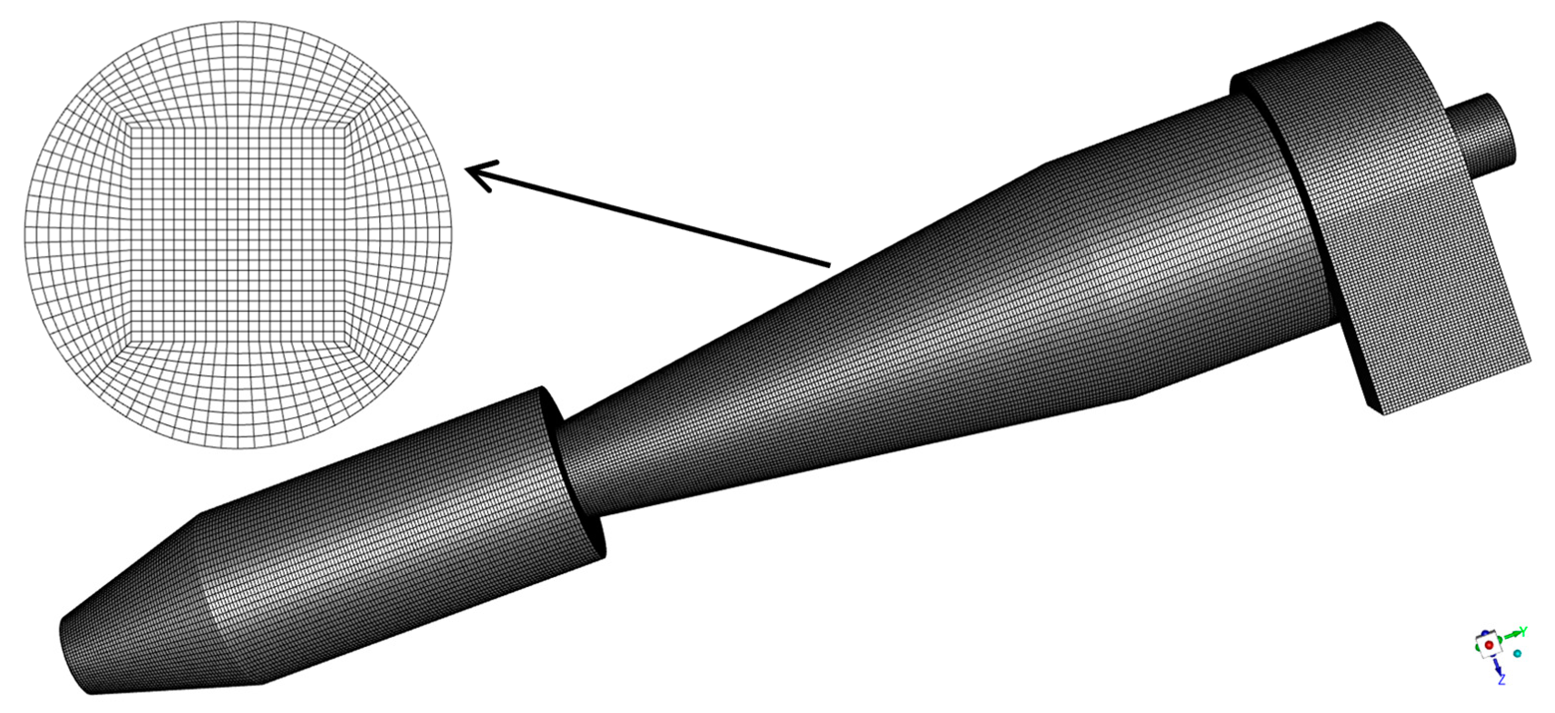
2.4. Grid Independence Analysis

The original cyclone separator is selected as an example. Different tested hexahedral grid numbers (700,000, 1,100,000, 1,480,000, and 1,880,000) are involved. Figure 3 depicts the variation in separator efficiency with particle diameter under different mesh numbers. The maximum difference of collection efficiency in cyclone between 700,000 and 1,100,000 mesh numbers is near 20%. The maximum difference of collection efficiency between 1,100,000 and 1,480,000 1,880,000 mesh numbers is less than 5%. The grid number of 1,100,000 is employed here, which is enough to guarantee convincing results. This meshed model of the cyclone separator is indicated in Figure 4.

2.5. Model Validation

In order to verify the accuracy of the numerical method, the simulation results were compared with the experimental data [44]. As shown in Figure 5, the pressure drop of the cyclone separator was compared at different inlet velocities. The simulation results are slightly larger than the experimental data overall. However, the overall error is not significant, which validates the model employed in present study.

3. Results and Discussion

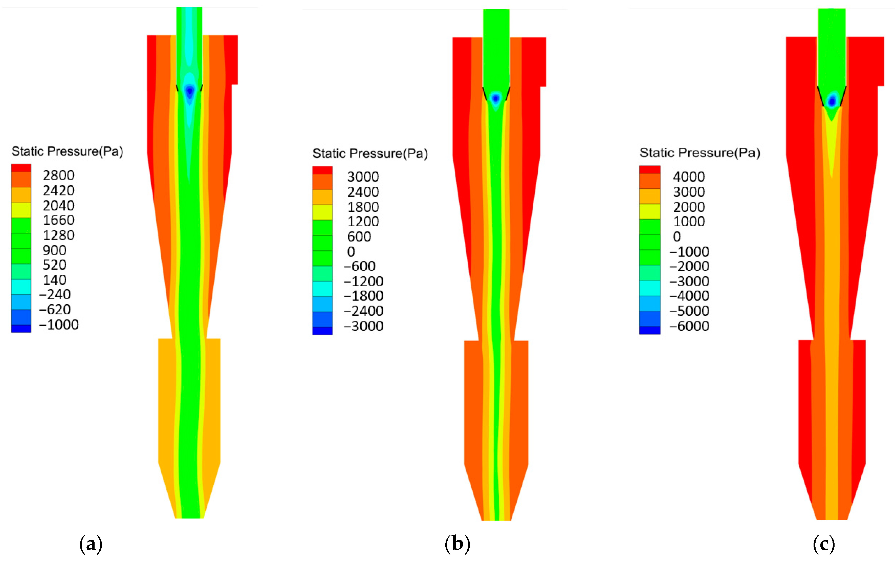
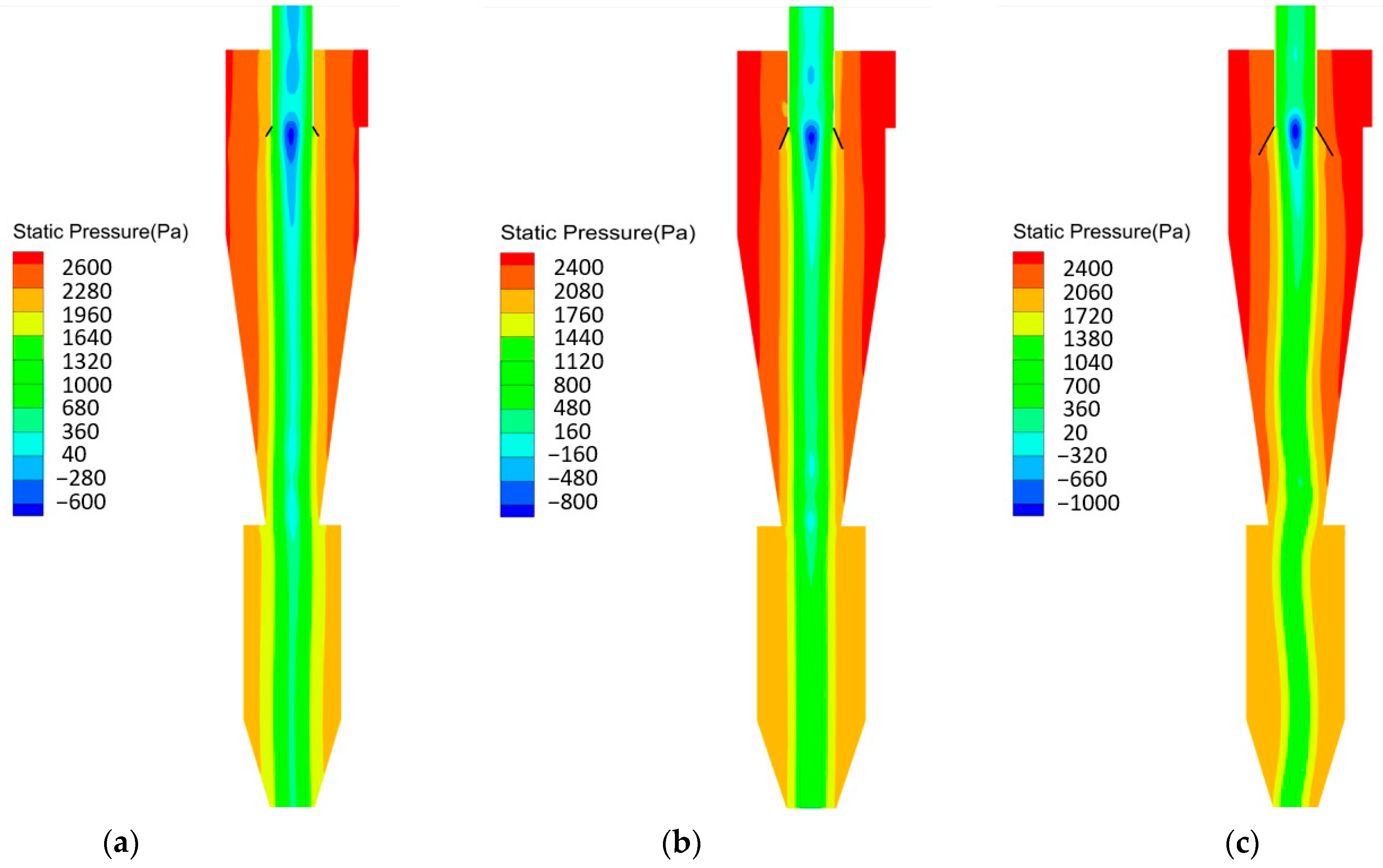
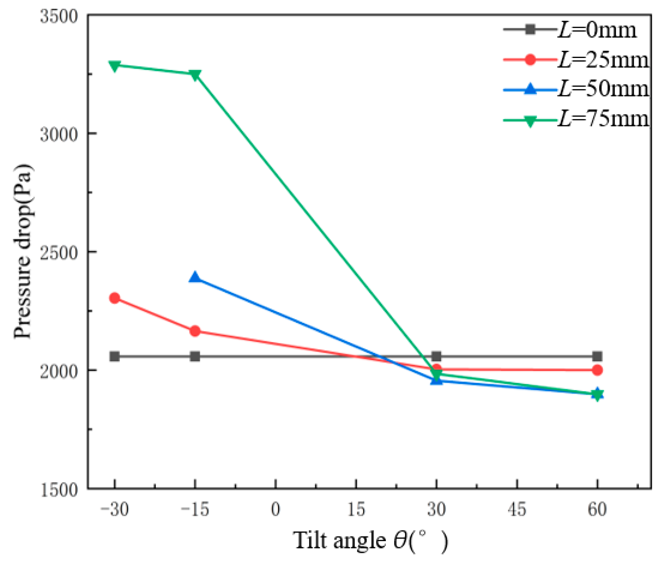
3.1. Pressure Drop Analysis

Figure 6 shows the static pressure distribution in the middle section of the cyclone separator under different divergent or convergent insertion pipes. It can be seen that the static pressure gradually decreases along the radial direction from the wall to the center. Furthermore, a clear low-pressure area appears in the center of the cyclone. This is because the gas phase in the cyclone creates an accelerated vortex motion from the outer wall to the center. As the gas phase gradually approaches the center, its static pressure is continuously transformed into dynamic pressure.
As can be seen from Figure 6, the presence of the divergent or convergent insertion pipes significantly affects the static pressure distribution. Compared with the original configuration, the overall pressure in the cyclone with the convergent insertion pipe of L = 75 mm and θ = −30° is higher. The static pressure distribution is more symmetrical with the narrowest low-pressure zone in the center. The asymmetry of static pressure distribution is most obvious in the original configuration. In the cyclone separator with the divergent insertion pipe of L = 70 mm and θ = 60°, the cyclone has the widest central low-pressure area, and the radial pressure gradient is also the smallest.
Figure 7 shows the static pressure distribution of the cyclone separator at different divergent insertion pipe lengths for θ = −15°. Near the vortex finder, there is a low-pressure core area with the lowest pressure in the cyclone separator. As the length L increases, the static pressure in this area becomes smaller; The central low-pressure area within the cyclone is narrower, while the overall static pressure of the cyclone is greater.
Figure 8 shows the static pressure distribution of the cyclone separator at different divergent insertion pipe lengths for θ = 30°. Near the vortex finder, there is a low-pressure core area with the lowest pressure in the cyclone separator. As the length L increases, the static pressure in this area also becomes smaller; The central low-pressure area within the cyclone is shortened. Near the outlet of the vortex finder, there also exists a low-pressure core area, which disappears at a greater length.
Figure 9 shows the pressure drop variation in the cyclone separator under different divergent or convergent insertion pipes. When the length L of the insertion pipes remains unchanged, the pressure drop of the cyclone separator gradually decreases with the increase in the angle θ. When θ = 30° and 60°, the pressure drop of the cyclone separator is lower than that of the case without the insertion pipe. The pressure drop reduction for L = 25 mm is not as obvious as that for L = 50 mm and 75 m. The pressure drop of the cyclone separator is significantly higher when θ = −30° and −15°; At the same angle θ, the longer the insertion pipe length L, the larger the pressure drop of the cyclone separator. At θ > 0°, the presence of the divergent insertion pipe will expand the intersection of the cylindrical region to the vortex finder. The longer the length, the larger the expanded area, which can effectively reduce the pressure loss in this area. However, when the length L is too long, it will impede the downward rotational motion of the vortex in the cylindrical region and increase the flow resistance. Therefore, the pressure drop at L = 75 mm is not significantly smaller than that at L = 50 mm; when L = 75 mm and θ = 60°, the pressure drop is reduced by 7.8%. On the contrary, when θ < 0°, the presence of the convergent insertion pipe increases the pressure loss from the cylindrical body to the vortex finder. The longer the length L, the smaller the intersection of the cylindrical region to the vortex finder, which leads to a greater pressure loss.

3.2. Axial Velocity

Figure 10 shows the axial velocity distribution at the Y = −420 mm and Y = −750 mm cross-sections of each cyclone separator, where Y is the Y-axis coordinate and the coordinate axis arrangement can be seen in Figure 1. The vertical axis is the ratio of axial velocity to inlet velocity, and the horizontal axis is the ratio of the radial position and the cross-section radius. As can be seen from Figure 10, the axial velocity distribution presents the inverted V-shaped distribution. The maximum axial velocity is located at the center of the cyclone separator. As can be seen from Figure 10, the cyclone flows downward near the separator wall, while the fluid flows upward near the central part. The reason is that the two-phase fluid from the inlet into the separator, according to the flow channel, to form a downward cyclonic flow. When reaching the vertebra, the fluid generates acceleration due to the change in vertebral angle. The different densities of the components produce different acceleration, resulting in differences in speed, and the acceleration of the solid particles is greater. Finally, due to the negative pressure effect of the vortex, a negative pressure zone is created in the central part of the separator, which guides the low density components upwards. Compared to the original configuration without insertion pipes, the maximum axial velocity is augmented with insertion pipes installed. The effect of the insertion pipe on the axial velocity distribution is mainly reflected in the central upward flow region. The effect is relatively small for the outer downward flow region. A smaller angle of the insertion pipe leads to a larger central axial velocity, such as θ = −30°, −15°, and 30°. For the divergent insertion pipes, the maximum central axial velocity increases with increasing tilt angles and then decreases. When θ = 60°, the axial velocity tends to be relatively small. As the insertion pipe length L increases, the impact on the axial velocity distribution is more obvious, which is reflected in not only the overall increase in axial velocity but also the more obvious asymmetry of axial velocity distribution.

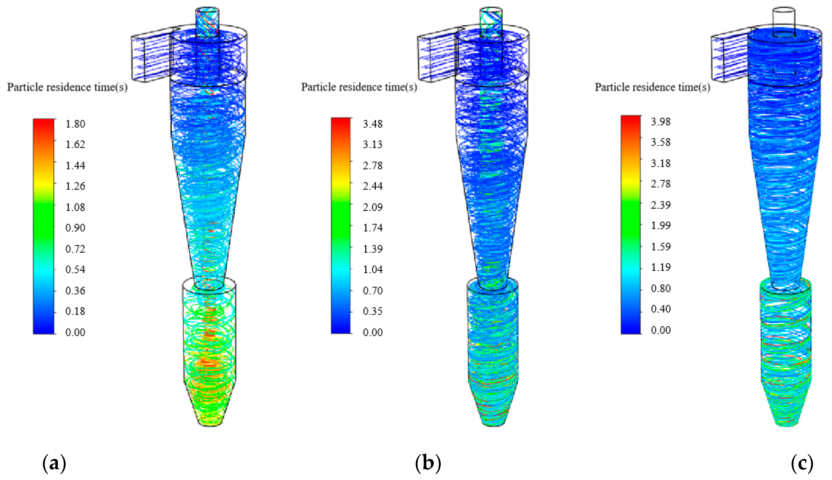
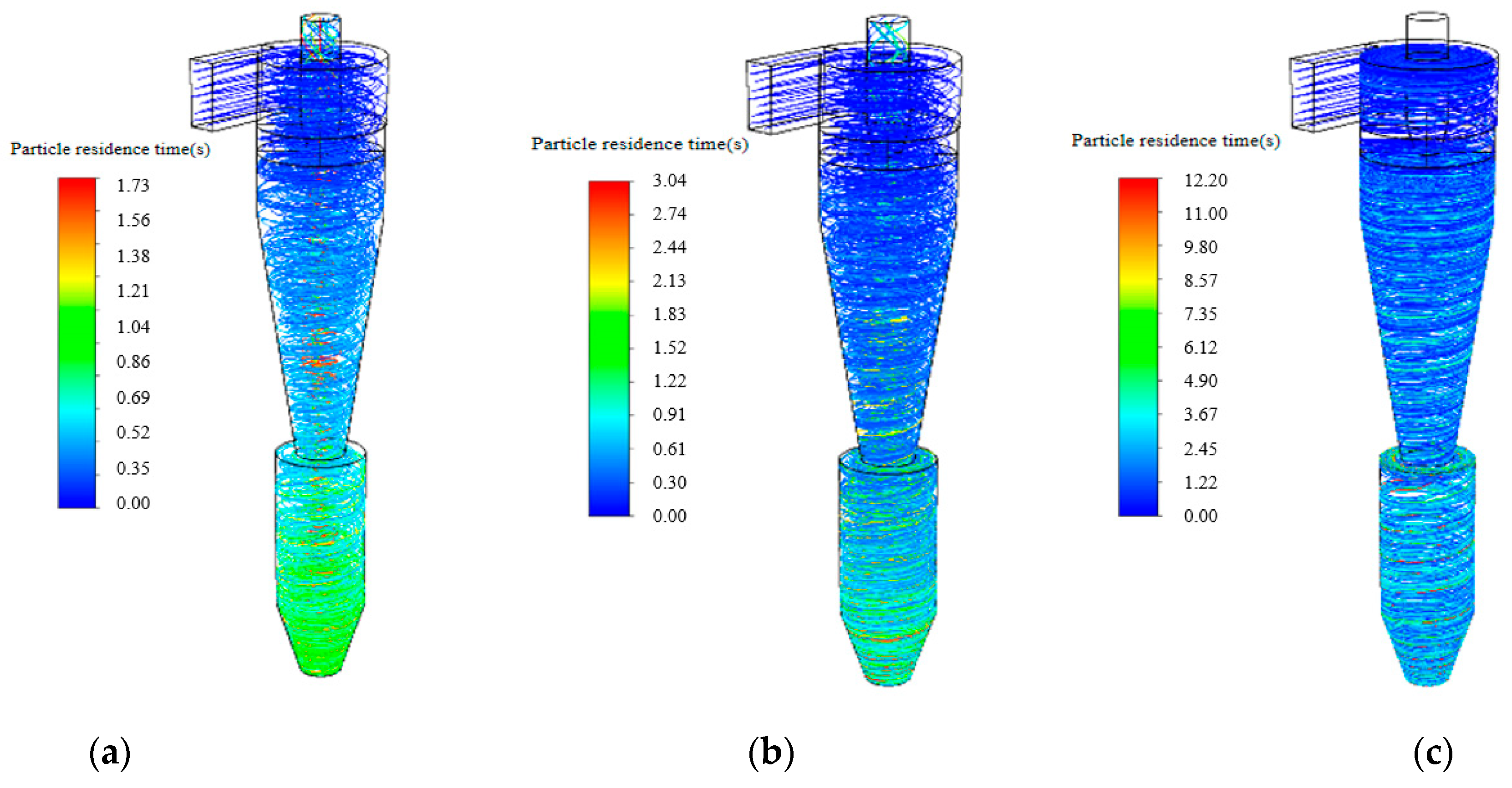
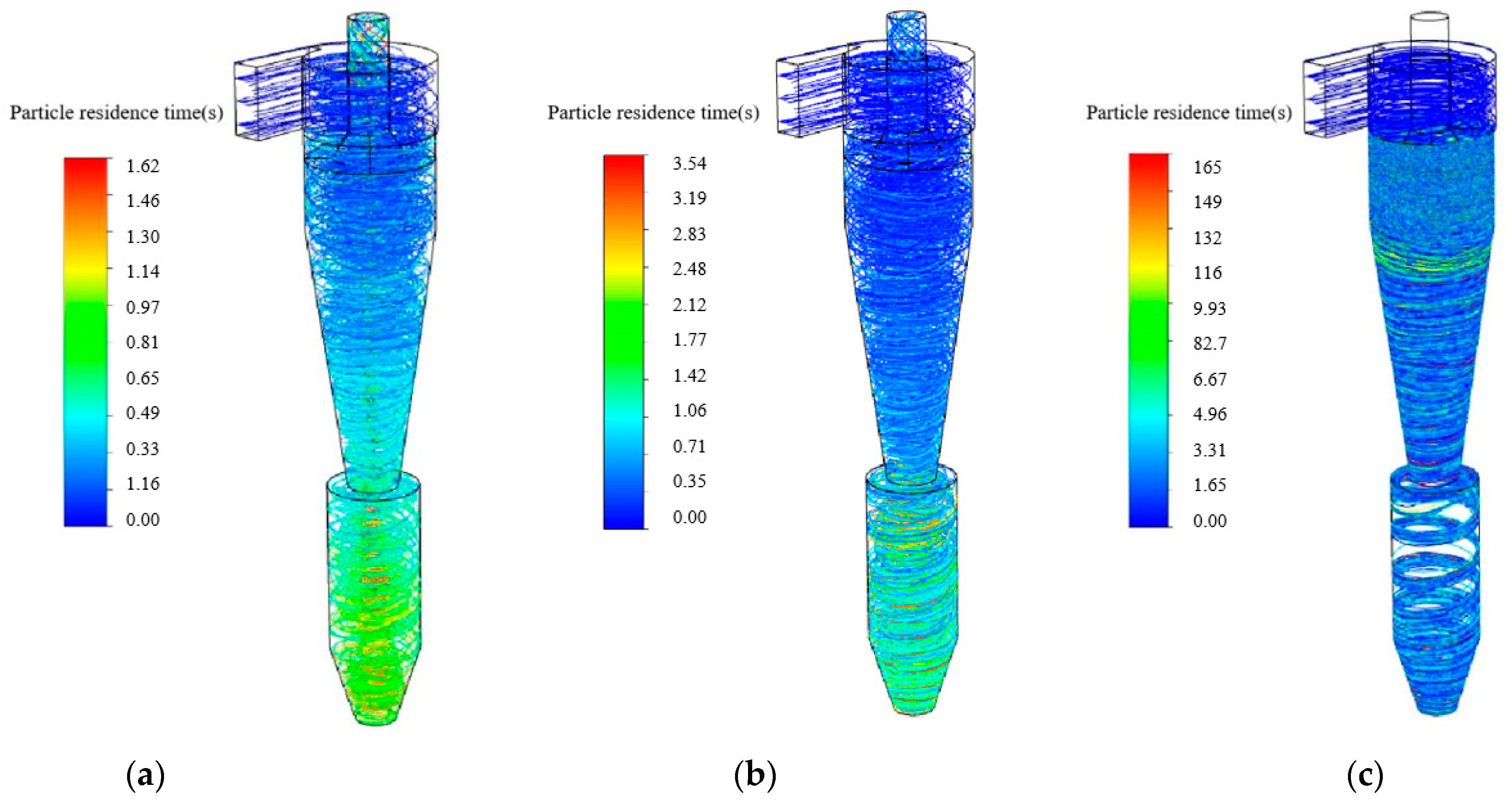
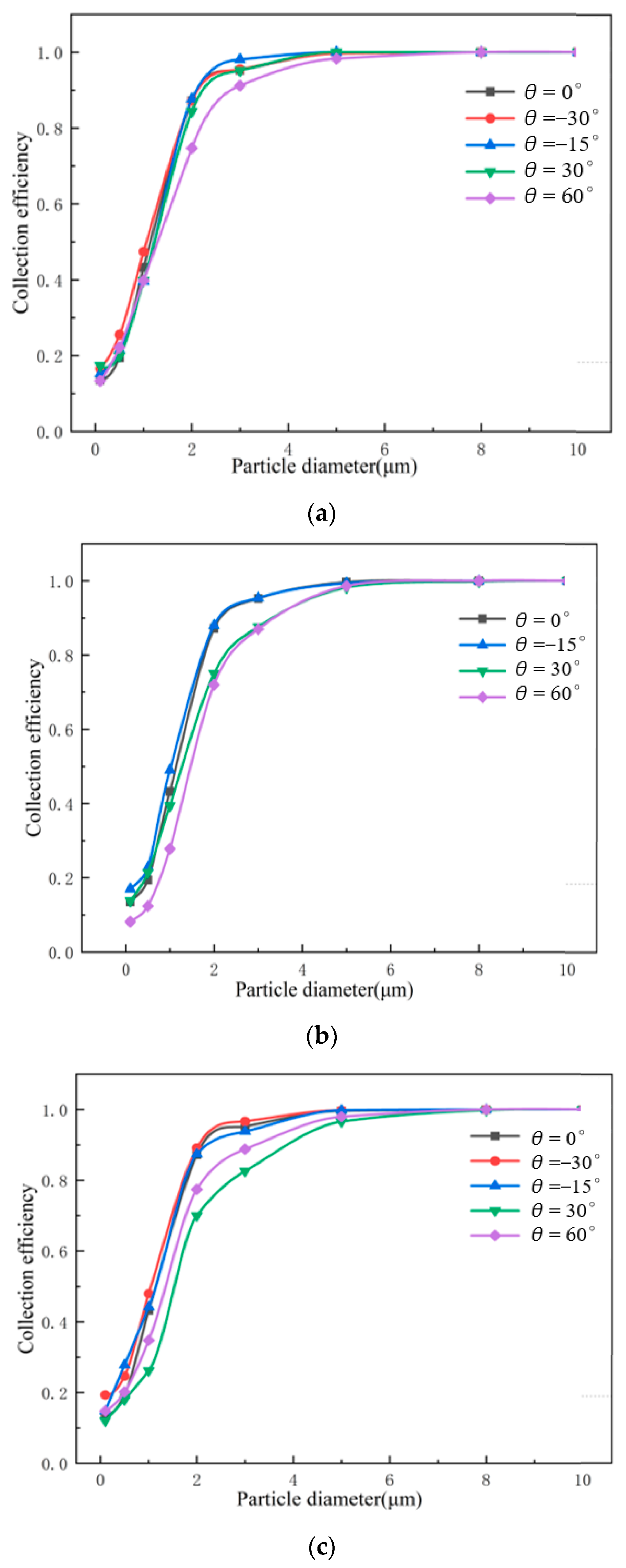
3.3. Particle Separation

Figure 11 depicts the particle movement in the cyclone separator for different particle diameters for the original cyclone separator. At a particle diameter dp = 0.1 μm, some particles escape from the vortex finder orifice, and the particles have a short residence time inside the cyclone. However, at the particle diameter dp = 10 μm, all particles reach the dust removal port, and the collection efficiency reaches 100%. After the particles enter the cyclone from the inlet, the particles are rotated inside the cyclone by centrifugal force under the airflow and gravity. The larger the particle diameter dp and the greater the gravity of the particle, the greater the corresponding centrifugal force. The particles are more likely to collide with the wall and fall to the bottom of the cyclone and be captured. Therefore, the collection efficiency increases with the increase in particle diameter. Small particles are carried by the airflow more easily as they are subject to less centrifugal force. They keep rotating with the airflow in the cyclone and eventually run out of the cyclone with the airflow or are finally captured. The interaction forces between particles ensure that there are a few particles in the cyclone separator to form a long period of circular motion.
Figure 12 and Figure 13 depict the particle movement in the cyclone separator under different particle diameters for cyclone separators with convergent and divergent insertion pipes. The same phenomenon exists. The number of escaped particles decreases with the increasing particle diameters. Compared to the original cyclone separator, the divergent insertion pipe can significantly decrease the particle resistance time under the situations of small and large particle diameters. However, the particle resistance time can be always obviously reduced under the studied range of the particle diameters.
Figure 14 shows the variation in separation efficiency with particle diameter under different insertion pipes. When the particle diameter dp ≥ 5 μm, the difference in the collection efficiency between the different separator configurations is rather small. The influence of the insertion pipes on the collection efficiency is weakened. The collection efficiency is above 95%. At the insertion pipe length L = 25 mm, the difference in the collection efficiency is relatively small due to the short insertion pipe. However, when θ = 60°, for particle diameter 1 μm ≤ dp ≤ 5 μm, the collection efficiency is significantly lower than in other situations. The larger the tilt angle, the larger the area of the lower side of the vortex finder, which augments the possibility of particle escape. For divergent insertion pipes of L = 50 mm and 75 mm, the collection efficiency is lowered when θ = 30° and θ = 60° due to the enlarged area of the lower side of the vortex finder. It is worth noting that under the divergent insertion pipes with L = 25 mm and L = 50 mm, the lowest collection efficiency occurs at θ = 60°, while when L = 75 mm, the lowest collection efficiency occurs at θ = 30°. For divergent insertion pipes (θ < 0°), the collection efficiency of the cyclone separator can be improved, especially under small diameter particles. The collection efficiency increases with increasing length and tilt angles. The most obvious collection efficiency improvement is achieved when L = 75 mm and θ = −30°, where the area of the lower side of the vortex finder is the smallest. In terms of collection efficiency and pressure drop, for small particles dp ≤ 5 μm, a convergent insertion pipe of L = 75 mm and θ = −30° exhibits better separation performance. When the particle diameter dp ≥ 5 μm, the divergent insertion pipes with larger angles and lengths can significantly decrease the pressure drop while guaranteeing satisfied collection efficiency.

4. Conclusions

In this study, different divergent or convergent insertion pipes below the vortex finder were constructed to improve separator performance. The impacts of different divergent or convergent insertion pipes were systematically analyzed. The following conclusions were obtained.
  • The insertion pipe can obviously affect the inside static pressure distribution inside. A longer insertion pipe length and larger tilt angle lead to wider central low-pressure areas and a smaller overall static pressure.
  • The installed convergent insertion pipe increases the pressure loss, while the installed divergent insertion pipe augments the pressure loss. When L = 75 mm and θ = 60°, the pressure drop is reduced by 7.8%.
  • With the insertion pipe installed, the maximum axial velocity is enhanced. A larger insertion pipe length contributes to the impact on the axial velocity distribution. For the divergent insertion pipes, the maximum central axial velocity increases with increasing tilt angles and then decreases.
  • For small particles dp ≤ 5 μm, a convergent insertion pipe of L = 75 mm and θ = −30° exhibits a better separation performance. When the particle diameter dp ≥ 5 μm, the divergent insertion pipes with larger angles and lengths can significantly decrease the pressure drop while guaranteeing satisfied collection efficiency.

Author Contributions

Conceptualization, M.W. and L.H.; methodology, L.H.; validation, J.W.; investigation, J.W.; resources, D.F.; data curation, M.W.; writing—original draft preparation, M.W.; writing—review and editing, E.M.; supervision, D.F.; funding acquisition, D.F. All authors have read and agreed to the published version of the manuscript.

Funding

This research was funded by [Hubei Technological Innovation Special Fund (Hubei Province Technological Innovation Major Project)] grant number [2019AAA010]. And The APC was funded by [2019AAA010].

Data Availability Statement

The data that support the findings of this study are available from the corresponding author upon reasonable request.

Conflicts of Interest

The authors declare no conflict of interest.

Nomenclature

DCyclone diameter, mm
DeVortex finder diameter, mm
aInlet height, mm
bInlet length, mm
h1Cylindrical body height, mm
h2Cylindrical height of expansion chamber, mm
h3Cone height of expansion chamber, mm
HCyclone height, mm
BCone-tip diameter, mm
BsDipleg diameter, mm
DsExpansion chamber diameter, mm
LInsertion pipe length, mm
θInsertion pipe angle, °
u i ¯ ,     u j ¯ ,     u k ¯ Mean velocities, m/s
ρDensity, kg/m3
D T , i j Diffusive transport term
D L , i j Molecular viscous diffusion term
P i j Stress generation term
G i j Buoyancy generation term
ф i j Pressure strain correlation term
F i j System rotation generation term
ε i j Dissipative term
kTurbulent kinetic energy at a node near the wall, J/kg
y*Fixed distance between node and wall, dimensionless
yDistance of a point near the wall from the wall, m
κ Karman number, dimensionless
Cμ, EStress constants
U Average velocity of the fluid near the wall, m/s
τ w Shear stress at the wall, Pa
m p Particle mass, kg
FSum of the particle swaying forces acting inside the grid cell, N
τ r Particle residence time, s
d p Particle diameters, μm
SFlow cross-sectional area, m2
CInlet wetted perimeter, m
μInlet gas viscosity, Pa·s
I Inlet turbulence intensity, %
D H Inlet hydraulic diameter, m
Subscripts
ggas
pparticle
i, j, k(=1, 2, 3) components in the Cartesian coordinate system

References

  1. Tang, Y.; Li, Z.; Wang, G.; He, Y. A novel approach for nature gas hydrate separation: Downhole spiral-cyclone coupled hydraulic in-situ separation. Chem. Eng. Res. Des. 2022, 188, 808–822. [Google Scholar] [CrossRef]
  2. Li, T.; Sun, Z.; Geng, K.; Sun, M.; Wang, Z. Numerical analysis of a novel cascading gas–liquid cyclone separator. Chem. Eng. Sci. 2023, 270, 118518. [Google Scholar] [CrossRef]
  3. Song, W.; Li, S.; Ouyang, Z. Operational performance characteristics of a novel fluidized bed with the internal separator for pulverized coal self-sustained preheating. Powder Technol. 2020, 361, 782–790. [Google Scholar] [CrossRef]
  4. Yang, H.; Wang, N.; Cao, Y.; Meng, X.; Yao, L. Effects of helical fins on the performance of a cyclone separator: A numerical study. Adv. Powder Technol. 2023, 34, 103929. [Google Scholar] [CrossRef]
  5. Feng, D.; Chang, X.; Zhang, X.; Li, S. The Research to Hydrocyclone Desander of Sand Removing Based on Crude Oil. Mech. Eng. Mater. 2012, 152, 1336–1341. [Google Scholar] [CrossRef]
  6. Zhang, L.; Fan, J.; Zhang, P.; Gao, F.; Chen, G.; Li, J. Effect of local erosion on the flow field and separation performance of the cyclone separator. Powder Technol. 2023, 413, 118007. [Google Scholar] [CrossRef]
  7. Zhu, L.; Wang, S.; Ru, Y.; Wang, J.; Yang, P.; Li, A.; Ma, Z.; Wang, Z. Numerical investigation on dynamic characteristics of flow field in cyclone separators with different dust hopper structures. Particuology 2023, 82, 134–145. [Google Scholar] [CrossRef]
  8. Wang, Q.Q.; Chen, J.Q.; Wang, C.S.; Ji, Y.P.; Shang, C.; Zhang, M.; Shi, Y.; Ding, G.D. Design and performance study of a two-stage inline gas-liquid cyclone separator with large range of inlet gas volume fraction. J. Pet. Sci. Eng. 2023, 220, 111218. [Google Scholar] [CrossRef]
  9. Jiao, J.; Liu, Z.; Zheng, Y. Evaluations and Modifications on Reynolds Stress Model in Cyclone Simulations. Chem. Eng. Technol. 2007, 30, 15–20. [Google Scholar] [CrossRef]
  10. Feng, D.; Huang, S.; Luo, L.; Ma, W. Prediction of liquid viscosity effect on flow field and performance in a solid-liquid hydrocyclone. Adv. Mater. Res. 2011, 318, 401–404. [Google Scholar] [CrossRef]
  11. Shukla, S.K.; Shukla, P.; Ghosh, P. Evaluation of numerical schemes using different simulation methods for the continuous phase modeling of cyclone separators. Adv. Powder Technol. 2011, 22, 209–219. [Google Scholar] [CrossRef]
  12. Feng, D.; Huang, S.; Luo, L.; Ma, W. CFD analysis of two-phase flow in a solid-liquid hydrocyclone. Appl. Mech. Mater. 2012, 130, 3640–3643. [Google Scholar] [CrossRef]
  13. Slack, M.D.; Prasad, R.O.; Bakker, A.; Boysan, F. Advances in Cyclone Modelling Using Unstructured Grids. Chem. Eng. Res. Des. 2000, 78, 1098–1104. [Google Scholar] [CrossRef]
  14. Brar, L.S.; Wasilewski, M. Investigating the effects of temperature on the performance of novel cyclone separators using large-eddy simulation. Powder Technol. 2023, 416, 118213. [Google Scholar] [CrossRef]
  15. Wei, Q.; Sun, G.; Gao, C. Numerical analysis of axial gas flow in cyclone separators with different vortex finder diameters and inlet dimensions. Powder Technol. 2020, 369, 321–333. [Google Scholar] [CrossRef]
  16. Griffiths, W.; Boysan, F. Computational fluid dynamics(CFD) and empirical modeling of the performance of a number of cyclone samplers. J. Aerosol Sci. 1996, 27, 281–304. [Google Scholar] [CrossRef]
  17. Le, D.K.; Guo, M.; Yoon, J.Y. A hybrid CFD—Deep Learning methodology to improve the accuracy of cut-off diameter prediction in coarse-grid simulations for cyclone separators. J. Aerosol Sci. 2023, 170, 106143. [Google Scholar] [CrossRef]
  18. Le, D.K.; Yoon, J.Y. A hybrid CFD—Deep learning methodology for improving the accuracy of pressure drop prediction in cyclone separators. Chem. Eng. Res. Des. 2023, 190, 296–311. [Google Scholar] [CrossRef]
  19. Gopalakrishnan, B.; Saravana Kumar, G.; Prakash, K.A. Parametric analysis and optimization of gas-particle flow through axial cyclone separator: A numerical study. Adv. Powder Technol. 2023, 34, 103959. [Google Scholar] [CrossRef]
  20. Guo, M.; Le, D.K.; Sun, X.; Yoon, J.Y. Multi-objective optimization of a novel vortex finder for performance improvement of cyclone separator. Powder Technol. 2022, 410, 117856. [Google Scholar] [CrossRef]
  21. Iozia, D.L.; Leith, D. The Logistic Function and Cyclone Fractional Efficiency. Aerosol Sci. Technol. 2007, 12, 598–606. [Google Scholar] [CrossRef] [Green Version]
  22. Iozia, D.L.; Leith, D. Effect of Cyclone Dimensions on Gas Flow Pattern and Collection Efficiency. Aerosol Sci. Technol. 1989, 10, 491–500. [Google Scholar] [CrossRef]
  23. Cortes, C.; Gil, A. Modeling the gas and particle flow inside cyclone separators. Prog. Energy Combust. Sci. 2007, 33, 409–452. [Google Scholar] [CrossRef]
  24. Elsayed, K.; Lacor, C. The effect of cyclone inlet dimensions on the flow pattern and performance. Appl. Math. Model. 2011, 35, 1952–1968. [Google Scholar] [CrossRef] [Green Version]
  25. Horvath, A.; Jordan, C.; Harasek, M. Influence of vortex-finder diameter on axial gas flow in simple cyclone. Chem. Prod. Process. Model. 2008, 3, 1–26. [Google Scholar] [CrossRef]
  26. Qian, F.P.; Zhang, M.Y. Effects of the Inlet Section Angle on the Flow Field of a Cyclone. Chem. Eng. Technol. 2007, 30, 1564–1570. [Google Scholar] [CrossRef]
  27. Tan, H.M.; Wang, J.J.; Jin, Y.H. The Investigation of Back-Mixing Particles near Dust Outlet in Cyclone Separator with Tangential Inlet. Adv. Mater. Res. 2011, 239–242, 2142–2148. [Google Scholar] [CrossRef]
  28. Liu, L.; Dou, H.-S.; Chen, X. Effect of particle diameter and injection position on the separation performance of cyclone separators. J. Comput. Multiph. Flows 2016, 8, 40–47. [Google Scholar] [CrossRef]
  29. Dehdarinejad, E.; Bayareh, M. Experimental and numerical investigation on the performance of a gas-solid cyclone with twisted baffles and roughened cone surface. Powder Technol. 2023, 420, 118401. [Google Scholar] [CrossRef]
  30. Dehdarinejad, E.; Bayareh, M.; Ashrafizaadeh, M. Impact of cone wall roughness on turbulence swirling flow in a cyclone separator. Chem. Pap. 2022, 76, 5579–5599. [Google Scholar] [CrossRef]
  31. Li, W.; Huang, Z.; Li, G. Improvement of the cyclone separator performance by the wedge-shaped roof: A multi-objective optimization study. Chem. Eng. Sci. 2023, 268, 118404. [Google Scholar] [CrossRef]
  32. Lee, J.W.; Yang, H.J.; Lee, D.Y. Effect of the cylinder shape of a long-coned cyclone on the stable flow-field establishment. Powder Technol. 2006, 165, 30–38. [Google Scholar] [CrossRef]
  33. Brar, L.S.; Sharma, R.P.; Elsayed, K. The effect of the cyclone length on the performance of Stairmand high-efficiency cyclone. Powder Technol. 2015, 286, 668–677. [Google Scholar] [CrossRef]
  34. Demir, S.; Karadeniz, A.; Aksel, M. Effects of cylindrical and conical heights on pressure and velocity fields in cyclones. Powder Technol. 2016, 295, 209–217. [Google Scholar] [CrossRef]
  35. Hamdy, O.; Bassily, M.A.; El-Batsh, H.M.; Mekhail, T.A. Numerical study of the effect of changing the cyclone cone length on the gas flow field. Appl. Math. Model. 2017, 46, 81–97. [Google Scholar] [CrossRef]
  36. Gimbun, J.; Chuah, T.G.; Choong, T.S.Y.; Fakhru’l-Razi, A. Prediction of the effects of cone tip diameter on the cyclone performance. J. Aerosol Sci. 2005, 36, 1056–1065. [Google Scholar] [CrossRef]
  37. Elsayed, K.; Lacor, C. Numerical modeling of the flow field and performance in cyclones of different cone-tip diameters. Comput. Fluids 2011, 51, 48–59. [Google Scholar] [CrossRef]
  38. Elsayed, K.; Lacor, C. The effect of the dust outlet geometry on the performance and hydrodynamics of gas cyclones. Comput. Fluids 2012, 68, 134–147. [Google Scholar] [CrossRef]
  39. Pandey, S.; Brar, L.S. On the performance of cyclone separators with different shapes of the conical section using CFD. Powder Technol. 2022, 407, 117629. [Google Scholar] [CrossRef]
  40. Parvaz, F.; Hosseini, S.H.; Ahmadi, G.; Elsayed, K. Impacts of the vortex finder eccentricity on the flow pattern and performance of a gas cyclone. Sep. Purif. Technol. 2017, 187, 1–13. [Google Scholar] [CrossRef]
  41. Guo, M.; Xue, H.; Pang, J.; Le, D.K.; Sun, X.; Yoon, J.Y. Numerical investigation on the swirling vortical characteristics of a Stairmand cyclone separator with slotted vortex finder. Powder Technol. 2023, 416, 118236. [Google Scholar] [CrossRef]
  42. El-Batsh, H.M. Improving cyclone performance by proper selection of the exit pipe. Appl. Math. Model. 2013, 37, 5286–5303. [Google Scholar] [CrossRef]
  43. Tan, F.; Karagoz, I.; Avci, A. Effects of Geometrical Parameters on the Pressure Drop for a Modified Cyclone Separator. Chem. Eng. Technol. 2016, 39, 576–581. [Google Scholar] [CrossRef]
  44. Hoekstra, A.J. Gas Flow Field and Collection Efficiency of Cyclone Separators; Technical University Delft: Delft, The Netherlands, 2000. [Google Scholar]
  45. Hugi, E.; Reh, L. Focus on solids strand formation improves separation performance of highly loaded circulating fluidized bed recycle cyclones. Chem. Eng. Process. 2000, 39, 263–273. [Google Scholar] [CrossRef]
  46. de Souza, F.J.; Salvo, R.d.V.; Martins, D.d.M. Effects of the gas outlet duct length and shape on the performance of cyclone separators. Sep. Purif. Technol. 2015, 142, 90–100. [Google Scholar] [CrossRef]
  47. Noé-Landry-Privace, M.B. Numerical Simulation of Dense Gas-Solid Separation in Cyclone Separators; Harbin Institute of Technology: Harbin, China, 2014. [Google Scholar]
  48. Singer, B.A. Modeling the Transition Region; NASA Report, the United States: Washington, DC, USA, 1993; NASA CR-4492.
  49. Launder, B.E.; Spalding, D.B. The numerical computation of turbulent flows. Comput. Methods Appl. Mech. Eng. 1974, 3, 269–289. [Google Scholar] [CrossRef]
  50. Azadi, M.; Azadi, M.; Mohebbi, A. A CFD study of the effect of cyclone size on its performance parameters. J. Hazard. Mater. 2010, 182, 835–841. [Google Scholar] [CrossRef]
Figure 1. Geometrical diagram of the reverse-flow cyclone separator.
Processes 11 02061 g001
Figure 2. Divergent or convergent insertion pipes.
Processes 11 02061 g002
Figure 3. Grid independence verification.
Processes 11 02061 g003
Figure 4. Schematic diagraph of the mesh representation.
Processes 11 02061 g004
Figure 5. Comparison of the pressure drop for the experimental and simulation results.
Processes 11 02061 g005
Figure 6. Static pressure contours of cyclone separators with different divergent or convergent insertion pipes. (a) L = 75 mm θ = −30°; (b) L = 0 mm; (c) L = 75 mm θ = 60°.
Processes 11 02061 g006
Figure 7. Static pressure distribution of the cyclone separator at different convergent insertion pipe lengths for θ = −15°. (a) L = 25 mm; (b) L = 50 mm; (c) L = 75 mm.
Processes 11 02061 g007
Figure 8. Static pressure distribution of the cyclone separator at different divergent insertion pipe lengths for θ = 30°. (a) L = 25 mm; (b) L = 50 mm; (c) L = 75 mm.
Processes 11 02061 g008
Figure 9. Pressure drop as a function of tilt angle and length under different divergent or convergent insertion pipes.
Processes 11 02061 g009
Figure 10. Axial velocity distributions under different divergent or convergent insertion pipes. (a) L = 25 mm Y = −420 mm; (b) L = 25 mm Y = −750 m; (c) L = 50 mm Y = −420 mm; (d) L = 50 mm Y = −750 m; (e) L = 75 mm Y = −420 mm; (f) L = 75 mm Y = −750 m.
Processes 11 02061 g010
Figure 11. Particle movement in the cyclone separator under different particle diameters for the original configuration. (a) dp = 0.1 μm; (b) dp = 1 μm; (c) dp = 10 μm.
Processes 11 02061 g011
Figure 12. Particle movement in the cyclone separator under different particle diameters for the convergent insertion pipe of L = 70 mm θ = −30°. (a) dp = 0.1 μm; (b) dp = 1 μm; (c) dp = 10 μm.
Processes 11 02061 g012
Figure 13. Particle movement in the cyclone separator under different particle diameters for the divergent insertion pipe of L = 70 mm θ = 30°. (a) dp = 0.1 μm; (b) dp = 1 μm; (c) dp = 10 μm.
Processes 11 02061 g013
Figure 14. The variation in collection efficiency with particle diameters under different divergent or convergent insertion pipes. (a) L = 25 mm. (b) L = 50 mm. (c) L = 75 mm.
Processes 11 02061 g014
Table 1. Dimensions of the cyclone separator.
ParameterValue
Cyclone diameter, D (mm)300
Length of the inlet, b (mm)73
Height of the inlet, a (mm)176
Parameter of the vortex finder
S (mm)276
De (mm)95
L (mm)25        50       75
θ (°)−30    −15    30    60
Disclaimer/Publisher’s Note: The statements, opinions and data contained in all publications are solely those of the individual author(s) and contributor(s) and not of MDPI and/or the editor(s). MDPI and/or the editor(s) disclaim responsibility for any injury to people or property resulting from any ideas, methods, instructions or products referred to in the content.

