Abstract
The cold box is a crucial component for cryogenic distillation in air separation units. With the increasing focus on energy conservation and emissions reduction, the integral hoisting of the cold box has emerged as a viable alternative to traditional cold box installation due to its highly efficient performance, short cycle time, and superior integration capabilities. Nonetheless, there are concerns surrounding the large size and weight of these boxes, as well as their eccentric structure, which can cause significant challenges during the integral hoisting process and pose safety hazards. To address these issues, this paper proposes a method for optimizing the lifting point of an extra-large cold box through dynamic simulation under actual working conditions. Firstly, a transient structure FEM simulation was carried out using multi-type mesh coupling based on the operating conditions of an extra-large cold box. Secondly, the posture and strength of the box during the hoisting process were analyzed to determine the most dangerous working conditions. Finally, the maximum equivalent stress of the trusses was employed as the fitness function of the particle swarm algorithm to optimize the lifting point position in the whole parameter range. The findings indicated that the most dangerous situation during the hoisting process occurred near the 0° working condition in the flip-up process and that optimizing the lifting point position based on this working condition significantly reduced the stress levels on the trusses.
1. Introduction
The energy, refining, and chemical integration industries are exploring new models for high-quality development as the global primary energy consumption structure tends toward clean, low-carbon, and diversified sources [1]. In light of this trend, extra-large air separation units (ASU) require high efficiency, short cycle time, and high integration of deep cryogenic cold box technology to meet the demands of the new industrial system and the “carbon neutral” objective [2,3,4]. Unlike traditional cold boxes, the installation of a cold box for an extra-large ASU requires assembly of its steel structure, tower equipment, and piping as one unit. As illustrated in Figure 1, the cold box for an extra-large ASU is typically installed using the integral hoisting method, since it has a large volume, heavy weight, and an eccentric structure, making hoisting challenging. To ensure that the steel structure of the trusses does not suffer from plastic deformation or damage during the hoisting process, a comprehensive analysis of the hoisting process is necessary. It is essential to design a reasonable hoisting structure and plan to guarantee the safety of the hoisting operation [5,6,7,8].
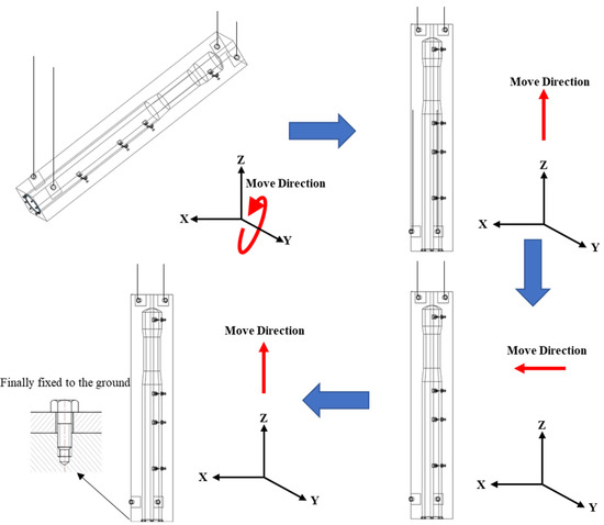
Figure 1.
The integral hoisting processes for an extra-large cold box.
The lug is a crucial component in ensuring the reliability of the hoisting process, as it is subjected to significant stress. To optimize its design, Choi, Kyung-Shin et al. [9] employed multivariate functions to determine its shape and conducted a structural analysis to identify the optimal aspect ratio. Similarly, Chapai Sushil [10] performed a comparative analysis of four different types of tail lug configurations using the finite element method and found that lug pair configurations exhibited lower local stresses than individual lug configurations. Park, J [11] further evaluated the performance of the connection between lugs and equipment through observations of the metal microstructure. The study assessed the effectiveness of the connection by analyzing the hardness and dilution values on the cross-sectional surfaces of the lugs, which ultimately improved the physical properties of the base material of the lug metal. Additionally, researchers have focused on optimizing other critical force areas in the hoisting process. For instance, Paik et al. [12] derived an approximate empirical formula for the initial deflection, enabling accurate initial deflection values to be obtained when calculating the ultimate strength of suspended reinforced slabs, while Zhang J et al. [13] proposed a theoretical model of rope segment tension at different positions to obtain dynamic rope tension and ensure the safety of the hoisting process. Since progressive failure is a major failure mode in dynamic processes [14], some researchers are focusing on it to ensure the safety of the dynamic hoisting process. Hu X et al. [15] developed a meso-scale phase filed model of cracking caused by corrosion of multiple reinforcements and predicted the development pattern of crack morphology and crack width. Zhang P et al. [16] further investigated the failure modes, developed a double-phase field model, and identified the failure mechanisms as well as other modes in matrix damage. However, these analyses predominantly focused on optimizing key components and evaluating their strength, with inadequate consideration of the eccentric structure. Consequently, full safety assurance of the integral structure during the hoisting process requires further research to address the potential risks of eccentric structures.
The safety of hoisting operations is closely tied to the state of force and deformation of the hoisting components. As such, extensive research has been conducted on this aspect. For instance, Wen Y [17] studied the design of a hoisting solution for the floating production storage and offloading (FPSO) living compartment while carrying out stress–strain and structural deformation simulations using finite element software. Additionally, Xiang S [18] developed an analytical theory that considers large geometric deformations and proposed a shape-finding method based on an iterative process. This method can predict the deformations, nodal forces, and bending moments of biaxially symmetric elastic lattice shells during hoisting construction. On the other hand, Shen M [19] used numerical simulations to evaluate the effectiveness of anti-deformation tooling and optimized anti-deformation control measures in the hoisting process. Those authors also employed finite element analysis and design optimization to develop a set of universal anti-deformation design solutions. Nonetheless, such studies mainly focused on finite element simulations using static structures, making it challenging to reflect stress changes during dynamic hoisting processes accurately. Therefore, this paper adopts transient finite element simulation based on the actual working conditions, which can fully reflect stress–strain situations and sufficiently guarantee the safety of the hoisting process.
Finally, in the hoisting of large-span thin-walled equipment, the differential design of the lifting point had been shown to cause changes in stress–strain during the hoisting process [20,21,22,23,24,25]. While some research has focused on selecting the position of the lifting point, there is a need for more studies on optimizing the lifting point position [20,23]. Furthermore, existing research has not considered the stress–strain situation during the dynamic hoisting process, which may lead to suboptimal results under actual working conditions. Therefore, this paper presents a transient structural finite element simulation to simulate the dynamic integral hoisting process of an extra-large cold box. Our simulations determined the maximum stress–strain condition of the trusses during the hoisting process more accurately and optimized the lifting point position based on actual working conditions. As such, the optimization proposed in this paper is closer to the actual situation, providing more guidance to the integral hoisting process and fully guaranteeing the safety of the extra-large cold box hoisting process.
2. Methodology
2.1. Simulation Model
2.1.1. Geometric Model Generation
This paper focuses on an extra-large cold box, which comprises steel trusses, cold box panels, the tower equipment, saddle supports, lugs, and the base ring. The dimensions of the cold box are 8.1 m × 7 m × 58.7 m, with a weight of 747.64 t. Q235B structural steel is used for steel trusses and cold box panels, Q345B steel for saddle supports, lugs, and the base ring, and 09MnNiDR steel for tower equipment. Table 1 [26,27] presents the main components, material parameters, and dimensional parameters. To improve the efficiency of finite element simulation and prevent the emergence of stress singularity, it is essential to simplify the model by eliminating accessories such as pipes that have minimal impact on stress and strain and rounding the contact tips. Figure 2 shows the simplified geometric model.

Table 1.
Model Parameters.
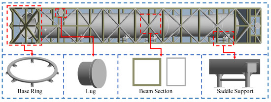
Figure 2.
Geometric model of an extra-large cold box.
2.1.2. Mesh Generation and Coupling
Once the geometric model is established, the next step is to mesh the model. In this paper, the trusses are modeled and meshed with 1D beam elements, where the central beam cross-section is a 300 mm × 300 mm hollow rectangle with a thickness of 12 mm, and the diagonally braced beam truss cross-section is a 300 mm × 200 mm hollow rectangle with a thickness of 10 mm. On the other hand, the cold box panels and tower equipment are thin-walled structures and are therefore modeled using 2D shell elements. The thickness of the cold box panels near the lugs is 30 mm, while the thickness of the rest of the area is 5 mm, and the thickness of the tower equipment is 20 mm. Additionally, the remaining structures not mentioned above are in 3D solid units. The final mesh division is illustrated in Figure 3.
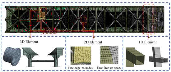
Figure 3.
Mesh model of an extra-large cold box.
In order to ensure the transfer of displacements between different parts of the mesh, it is necessary to establish connections in the contact area. Previous research has suggested using specific coupling methods between different types of grid elements, which are presented in Table 2 [28,29,30]. Based on this, this paper adopts node coupling for displacement transfer between elements of the same type. Furthermore, node coupling is utilized between 1D beam elements and 2D shell elements. For the connection between 1D beam elements and 3D solid elements, as well as between 2D shell elements and 3D solid elements, multi-point constraints (MPC) contact is employed. The MPC algorithm is considered more suitable for binding contact and non-separation constraint and can support significant deformation.
Table 2.
Grid coupling recommendations.
2.1.3. Boundary Conditions
The model is subjected to standard gravity in the Z-direction and an ambient temperature of 22 °C. The remote points at the end (points A and B in Figure 4) are located 40 m away from the positive Z direction of the tail lugs, while the remote points at the top (points C and D in Figure 4) are located 60 m away from the positive Z direction of the top head lugs. The slings are simulated using the spring units to connect the bearing surface of the lugs with the corresponding remote points. The stiffness of the spring unit is set to 1 × 10⁸ N/mm [31], and it is set to tensile only to more accurately simulate the force of the sling. In order to simulate the integral hoisting process of an extra-large cold box, during the transient structural hoisting simulation, the displacement of the remote points is set based on actual crane movement conditions. The specific boundary conditions are illustrated in Figure 4.
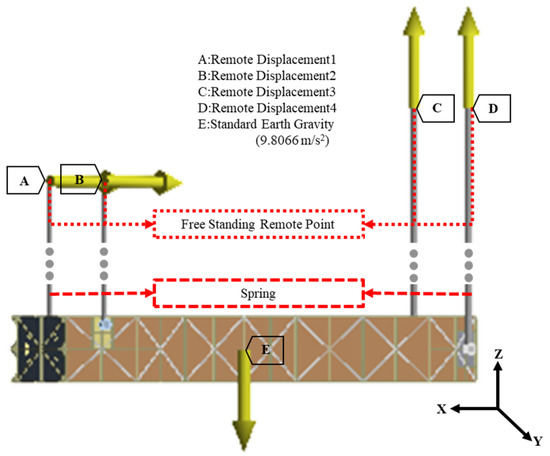
Figure 4.
Boundary conditions for finite element simulation.
2.1.4. Grid Independence and Validation
Before conducting the numerical simulation, the number of mesh elements is adjusted to ensure grid independence. ANSYS Workbench 2020 is utilized to perform simulations on an extra-large cold box, as depicted in Figure 3. To minimize unnecessary calculations, solely the initial 60 s hoisting process is simulated. As the trusses are the primary focus of the hoisting process, the impact of mesh elements is evaluated via changes in stress on the trusses. Figure 5 indicates that the maximum stress on the trusses nearly ceases to vary when the number of elements reaches 155,375, with a change rate below 0.5%. Hence, to enhance computational efficiency and conserve resources, subsequent calculations will employ the grid size setting corresponding to the grid number 155,375. The maximum stress serves as an output parameter and an objective function for the subsequent optimization process. It is essential to note that the stress refers to the equivalent (von Mises) stress, as per the fourth strength theory [32]:
where is the equivalent stress and , , and are the three directions of the main stress.
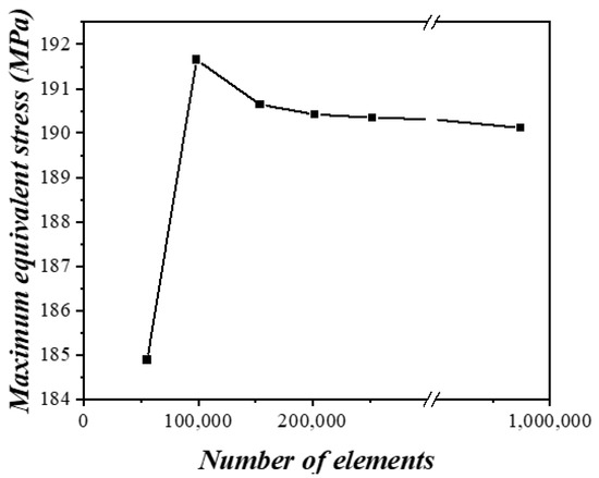
Figure 5.
Grid independence test for transient structural hoisting simulation.
2.2. Optimization Model
This paper proposes a novel approach to optimize the hoisting process by considering the actual hoisting conditions. The proposed method involves changing the position of the lifting point using an optimization algorithm to minimize the equivalent stress. The entire optimization process is presented in Figure 6, which can be categorized into three parts. Firstly, the transient structure finite element simulation of the actual integral hoisting process of the extra-large cold box is conducted. Secondly, the hoisting process is analyzed to identify the time point of the maximum stress under actual working conditions. Finally, the lifting point position is optimized to minimize the equivalent stress. The purpose of the finite element simulation and analysis is to determine the time point at which maximum stress occurs during hoisting under actual working conditions. Optimization is based on this timing, which is more effective in terms of avoiding safety issues during the hoisting process.
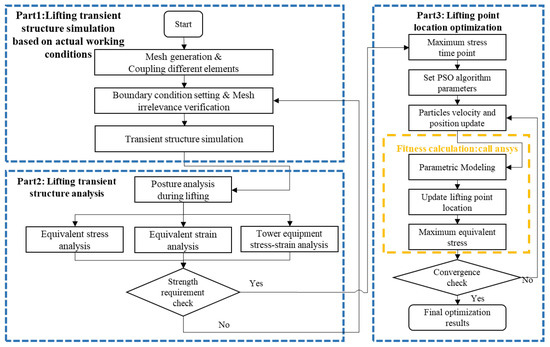
Figure 6.
Flowchart of transient simulation and optimization for the integral hoisting of an extra-large ASU Cold Box.
The determination of boundary conditions for the integral hoisting of an extra-large cold box is based on the actual working conditions. Subsequently, a transient structural finite element simulation of the hoisting process is conducted. The results of the finite element simulation are analyzed, with a focus on the hoisting posture, equivalent stress, and strain changes during the simulation process. Specifically, the analysis centers on the time point of the maximum equivalent stress, which is considered the most dangerous point of the hoisting process. The calculation is performed to determine whether the equivalent stress falls within the allowable material stress range. Based on the analysis results, the lifting point is further optimized. To improve the calculation efficiency, static structural analysis is utilized for the optimal design of the lifting point. The boundary conditions in the static analysis are consistent with those in the transient analysis at the time point of the maximum equivalent stress. The static structure simulation is made more realistic by adding a dynamic load factor.
The optimization of the lifting point is conducted using the particle swarm optimization algorithm (PSO) with joint simulation in Matlab and Ansys. Initially, the PSO parameters are set in Matlab, and the lifting point position information is generated based on relevant parameters. Subsequently, Matlab is used to update the lifting point position and conduct the simulation in Ansys. The calculated maximum value of the equivalent stress is then transmitted back to Matlab. Finally, the PSO is iteratively optimized to determine the optimal position of the lifting point based on the transmitted equivalent stress value. This approach is compared with the method of generating a database using Ansys simulation and performing optimization, wherein the Ansys simulation in this paper serves as a fitness function in the PSO optimization process, enabling more precise optimization within the defined range.
The PSO algorithm is a widely used population-based optimization technique in intelligent computing. The optimal solution is found by continuously updating the position; the update formula is as follows [33]:
where V is the velocity of particles; X is the position of particles; is the number of current iterations; and are acceleration factors, which are non-negative constants; and are random numbers within the interval [0,1]; is the optimal value position of the current population; is the optimal value position among all populations; and is the inertia weight, which reflects the ability of the particle to inherit the previous velocity, and the magnitude of its value determines whether the algorithm focuses on a global or local search. Therefore, this paper uses the following linearly decreasing inertia weights in order to better balance the global search and local search capabilities:
where is the initial inertia weight; is the inertia weight at the maximum number of iterations; is the current number of iterations; and is the maximum number of iterations.
3. Results and Discussion
This paper employs the transient structure in Ansys Workbench 2020 to conduct simulations of the four stages of hoisting, namely flip-up, lift-up, translation, and descent. To replicate the actual integral hoisting conditions of the extra-large cold box, constraints are imposed based on the boundary conditions illustrated in Figure 4, with a simulation time of 5700 s. The remote point rotation is unrestricted in all directions; its displacement is depicted in Figure 7. Specifically, Figure 7a portrays the folding displacement of points A and B, while Figure 7b presents that of points C and D. After the completion of the first stage, where the hooks of tail lugs are disengaged, the displacement constraint is limited to 2700 s for points A and B, corresponding to the moment when the first process concludes.
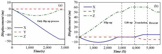
Figure 7.
Variation in the displacement of the lifting point: (a) lifting point A and B; (b) lifting point C and D.
3.1. Hoisting Posture Analysis
This paper mainly simulates the four states during the integral hoisting process of an extra-large cold box; the obtained equivalent stress is shown in Figure 8. Figure 8a shows the stress contour of the flip-up working state. During this time, the top of the transverse-mounted extra-large cold box is lifted continuously and finally becomes the vertical state. Meanwhile, this process is the most complicated stage of stress change in the whole process. Figure 8b shows the stress contour of the lift-up working condition. This process is to prevent the tail of the extra-large cold box from touching the ground while the hooks of tail lugs are disengaged. Figure 8c shows the stress contour for the translating working condition. Generally, there is a distance deviation between the extra-large cold box and the installation point after the previous two stages are completed. The limitations of the work site and the hoisting error cause this deviation, so translation is needed. Figure 8d shows the stress contour of the descent working state. After the extra-large cold box is moved to the installation position, it needs to be lowered to the ground and then fixed there to complete the hoisting process. The result of each stage shows that the posture is stable during the hoisting process. Meanwhile, this indicates the absence of dangerous working conditions, such as a shift in the center of gravity.
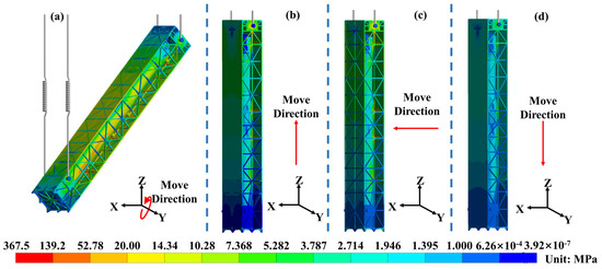
Figure 8.
Equivalent stress for each stage of hoisting: (a) flip-up; (b) lift-up; (c) translation; (d) descent.
This section aims to evaluate the accuracy of the integral hoisting process in the extra-large cold box installation by comparing the simulated posture and the designed installation posture. The position error is calculated at the termination of each hoisting process, and the data obtained are presented in Table 3. Notably, the mean value of the error in the Z-direction is found to be the largest for the extra-large cold box during integral hoisting. This is attributable to the elongation of the slings due to the force of gravity in the Z-direction during the simulation process, which is often overlooked in theoretical designs. Despite this, the maximum position error value observed is 1.689 × 10⁻² m, while the final error value is 1.537 × 10⁻² m, both of which fall within the acceptable error range. As such, the findings suggest that the proposed hoisting process is safe and feasible.
Table 3.
Position error.
3.2. Mechanical Performance Analysis
The safety and stability of a hoisting project are heavily reliant on the structural strength of its components. In the case of extra-large cold boxes, the strength of the trusses is particularly critical to ensure safe hoisting practices, while the stress and strain placed upon the tower equipment can significantly impact the serviceability of the overall structure. To address these concerns, this section conducts a thorough analysis and calibration of both the trusses and tower equipment strength.
3.2.1. Analysis of Mechanical Properties of Tower Equipment
In the integral hoisting process, the tower equipment inside the extra-large cold box will be deformed under the action of external forces, which will affect the internal structure arrangement and potentially reduce the performance of the tower equipment. Therefore, the equivalent force change of the tower equipment not only affects the safety of integral hoisting but also affects the final performance of the extra-large cold box, so it is important to carry out strength calibration. Figure 9 shows the maximum value of the equivalent stress and the equivalent strain of the tower equipment in the hoisting process over time. The tower equipment is only affected by gravity and dynamic load during the hoisting process. Meanwhile, the positive pressure of the tower equipment is positively related to (where is the gravity of the tower equipment and is the angle between the tower equipment and the horizontal direction). During the flip-up process, goes from 0° to 90°, so the equivalent stress of the tower equipment decreases continuously. Then, remains constant during the subsequent process, and therefore, the equivalent stress remains almost constant. Similarly, the strain is the stress divided by the modulus of elasticity, so the strain trend is the same as the stress. The strains mentioned above are also referred to as the equivalent strain, which is shown in the equation below under the von Mises criterion [34]:
where is the equivalent strain, is the strain in different directions, and ij is the strain in different directions.
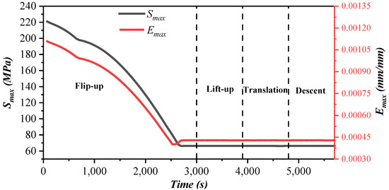
Figure 9.
Maximum equivalent stress and strain of tower equipment over time.
The maximum equivalent stress Smax_Vessel = 220.92 MPa and the maximum equivalent strain Emax_Vessel = 0.11% occur during the flip-up process. The stress contours of the tower equipment during the flip-up process are depicted in Figure 10, which illustrates that the highest stress level occurs in the working condition of θ = 0°, specifically, in the contact section between the tower equipment and the first saddle support. Table 1 shows that the tower equipment is made of 09MnNiDR material, which has no significant yield limit, so the stress value that produces 0.2% residual deformation is specified as its yield limit Sy_Vessel ≥ 300 MPa [27]. As such, we have:
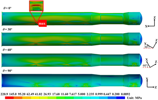
Figure 10.
Equivalent stress result of tower equipment analysis.
Therefore, the tower equipment is in a flexible state, and the structure is safe. The deformation of the tower equipment during the integral hoisting process is minimal and has little impact on the performance of the extra-large cold box.
3.2.2. Analysis of the Mechanical Properties of Trusses
During the hoisting process, the trusses play a crucial role as the central unit subjected to forces. However, the equivalent stress changes in the trusses during dynamic hoisting processes are often challenging to calculate accurately using numerical methods alone. Therefore, it is essential to undertake a finite element analysis of the truss structure to gain a more comprehensive understanding of this phenomenon. Figure 11 presents a line graph depicting the maximum value of the equivalent stress and maximum principal elastic Strain of the trusses over time during the hoisting process. The graph shows that the equivalent stress remains high for the first 200 s (approximately 190.00 MPa) and then gradually decreases until it stabilizes (around 71.20 MPa). This variation arises from the significant speed changes at the beginning of the lift, which lead to increased external loads due to high acceleration. As the speed of the subsequent hoisting process gradually smoothens out, the stresses continue to decrease. Additionally, after completion of the flip-up process, the subsequent hoisting process typically occurs at a constant speed without any dynamic load. Consequently, the stresses remain mostly stable during the subsequent hoisting stages. Similarly, the strain is the stress divided by the modulus of elasticity, so the strain trend is the same as the stress.
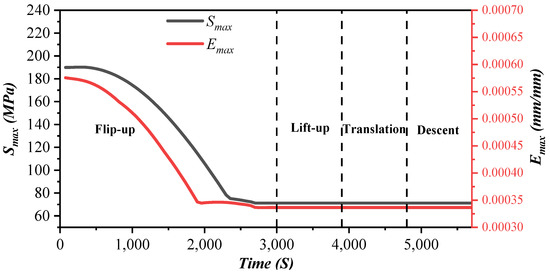
Figure 11.
Maximum equivalent stress and maximum principal elastic strain of trusses over time.
During the whole hoisting process, the maximum value of the truss equivalent stress Smax_Truss = 190.52 MPa and the maximum principal elastic strain Emax_Truss = 0.058%, near the θ = 0° working condition of the flip-up process. Figure 12 shows the stress contour of the trusses during the flip-up process; the maximum equivalent stress of the trusses appears at the connection between the first saddle support and the trusses. The stresses are evenly distributed in Figure 12, which indicates that the truss structure is well-designed. Table 1 shows that the trusses are made of Q235B material; its yield strength Sy_Truss = 241.4 MPa, and the structural weld coefficient is 0.85. Therefore, we have
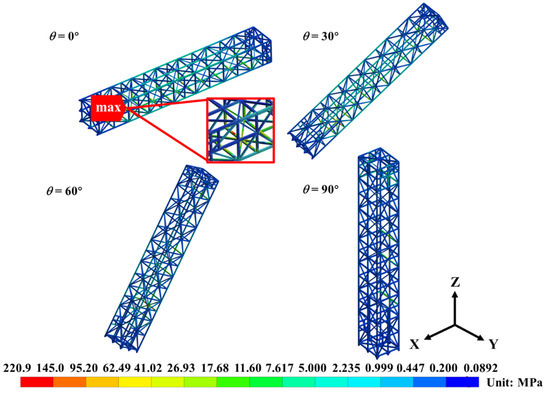
Figure 12.
Equivalent stress result of truss analysis.
As such, the truss body of the extra-large cold box is in a flexible state and is structurally safe.
During the simulation of the hoisting process, it was found that while the strength checks for the essential components met the requirements, the equivalent stress of the trusses approached its yield limit, reaching 92.8% of the stress limit. This proximity to the yield limit increases the likelihood of accidents, especially in adverse conditions, such as high winds during construction. Therefore, it is crucial to optimize the design of the hoisting scheme to reduce the equivalent stress and ensure sufficient safety margins.
3.3. Optimal Design of Lifting Points
The findings presented in Section 3.2 indicate the necessity for the hoisting design to undergo further optimization. Additionally, studies have demonstrated that differential lifting point designs can cause stress and strain changes during the hoisting process [19,22,23]. Consequently, this paper aims to optimize the position of the lifting point to improve the overall performance of the hoisting scheme.
The simulation of Section 3.2 took a total of 21.2 h. With this setup, joint simulation optimization on Matlab-Ansys is computationally redundant and difficult to implement. Therefore, the finite element simulation model needs to be further simplified. As the optimization is for the stresses on the truss section and is not concerned with the stresses on the internal tower, lugs, saddle supports, or the base ring components, the geometric model can be further simplified to improve the computational efficiency. In this paper, a point mass is used to simulate the application of forces on the trusses by the internal components of the extra-large cold box. The point mass is set at the center of gravity of the internal components with a mass that is the sum of the masses of the internal components. Meanwhile, the point mass acts on the contact area where the forces are transferred between the components, as shown in Figure 13.
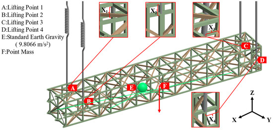
Figure 13.
Boundary conditions for static structure simulation.
The transient structural simulation of the whole hoisting process is highly time-consuming, while the simulation in Section 3.2 has already shown that the trusses have the highest equivalent stress at around the θ = 0° working condition. Therefore, the static structural simulation of the 0° condition is used instead of the transient structural simulation to improve the calculation efficiency. In order to achieve an accurate substitution, the static structural simulation requires the addition of a dynamic load factor. Figure 14 shows the variation of the maximum equivalent stress with the change in the dynamic load factor. The comparison in Figure 14 shows that the static structural simulation results are well coupled with the transient structural simulation results when the dynamic load factor is 1.7. The maximum value of the equivalent stress of the trusses is 189.41 MPa at this time, which is 0.58% different from the transient structural simulation and is within the error tolerance limits. Therefore, the dynamic load factor is set to 1.7 in the subsequent optimization process of this paper.
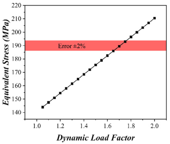
Figure 14.
Maximum equivalent stress of a static structure against the dynamic load factor.
According to the design principle of lifting point and lug size, the variation range of the tail lifting point in this paper is 0~2.5 m, and the variation range of the top head lifting point is 0~2 m. The position variation of each lifting point is denoted by X1–X4, with their specific meanings depicted in Figure 13. Notably, X1 and X2 change synchronously, as do X3 and X4, with the exact range of these changes indicated in Table 4. This section considers the maximum equivalent stress of the trusses S1 and the maximum equivalent stress of the beam where the lifting point is located at S2 to ensure the safety of hoisting fully. Taking normalization into consideration, which regards the range of configuration parameters as a unit, the stress variation against the location of the lifting point is shown in Figure 15.
Table 4.
Range of lifting point position parameters.
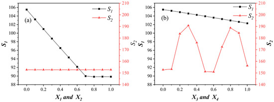
Figure 15.
Stress variation against the location of the lifting point: (a) lifting point A and B; (b) lifting point C and D.
Figure 15a exhibits the trend of stress variation when X1 and X2 are increased while keeping X3 and X4 constant. The results show that S1 initially decreases with the increase of X1 and X2. A further increase in X1 and X2 leads to a smooth plateau in S1 at a variation range of approximately 0.7. However, S2 remains unaffected by variations in X1 and X2, with no change in stress levels throughout the range of variation, i.e., they remain stable at around 153 MPa. In contrast, Figure 15b displays the trend of stress variation when X3 and X4 are increased while keeping X1 and X2 constant. During this process, S1 consistently decreases with the increase of X3 and X4. Meanwhile, S2 reveals two waves of change with an increase in X3 and X4, with the minimum stress value near the variation range of 0.6.
The preceding variation analysis demonstrates that changes in the position of the lifting point have a notable impact on stress levels. Additionally, the optimized range of the lifting point position corresponds to a minimum stress value. As a result, we propose the subsequent optimization model for the position of the lifting points:
where S1 is the maximum equivalent stress of the trusses and S2 is the maximum equivalent stress of the beam where the lifting point is located.
Matlab is used to implement the PSO with the following parameters: learning factor C1 = C2 = 1.49445, maximum number of iterations = 200, number of populations Pop_size = 20, initial inertia weight = 0.9, and inertia weight at the maximum number of iterations = 0.4. In the PSO, the lifting point position variables X1~X4 are used to calculate fitness, which is passed to Ansys for the finite element simulation. The parametric model in Ansys updates the position of the lifting points based on these variables. Subsequently, S1 and S2 values are calculated and return to the PSO as fitness values. The lifting point positions are continuously updated by the PSO to calculate the equivalent stress iteratively. Figure 16 illustrates the iterative changes in the fitness values and lifting point positions.
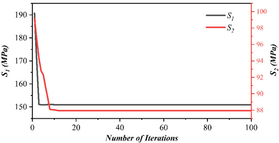
Figure 16.
Lifting point optimization process.
The optimum value is obtained after 13 generations of PSO. Meanwhile, the maximum equivalent stress of the trusses is 150.97 MPa, which is 20.76% less than before optimization. The maximum equivalent stress of the beam where the lifting point is located is 87.96 MPa, which is 16.63% less than before. A static structural finite element simulation is then carried out using the optimized lifting point parameters, and a comparison of the main parameters before and after optimization is shown in Figure 17. It can be seen from the Figure 17 that the parameters are effectively reduced after optimization, with the most significant change in the maximum equivalent strain, which is reduced by 32.14%, giving the best optimization effect. After optimization, the maximum equivalent stress of the trusses accounts for 73.57% of the yield limit, and the safety margin is improved. Overall, the above results show that the optimization of the position of the lifting point is of great significance in ensuring the safety performance of the integral hoisting process of extra-large cold boxes.
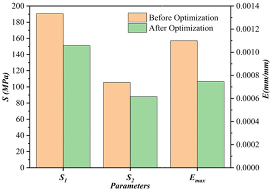
Figure 17.
Comparison of the main parameters before and after optimization.
4. Conclusions
This paper proposed a method to optimize the lifting point of an extra-large cold box based on the actual working conditions. In the first stage, the transient structure was used for finite element simulation according to the actual working conditions of the integral hoisting. Among them, different types of mesh elements were used for modeling and coupling according to the geometric characteristics of different components in the large cold box. This approach dramatically reduced the number of finite element simulation meshes and improved computational efficiency. In the second stage, the finite element simulation results were analyzed to assess the posture of the extra-large cold box and the strength of the trusses and the tower equipment during the hoisting process. The analysis revealed that the posture of the cold box remains stable and the structural strength was within the yield limit under the hoisting scheme, thus ensuring safe and stable hoisting. Moreover, the equivalent stress change curve indicated that the maximum equivalent stress and equivalent strain change occurred at the 0° working condition, which was the most dangerous working condition and therefore the condition to be optimized. In the third stage, a working condition near 0° was used as the simulation condition, and a static structure with a dynamic load factor was employed to optimize the position of the lifting point. After optimization, the maximum equivalent force and strain of the trusses were reduced by 20.76% and 30.14%, respectively.
Compared to prior research [19,20,23,24], the optimization outcomes presented in this paper offer more practical insights for engineering applications. These findings were derived from a simulation optimization approach that focused on identifying the most hazardous points during hoisting operations under actual working conditions. Notably, Ansys played a crucial role in determining the degree of PSO adaptation during the optimization process, which led to identifying optimal points within the specified parameter range. Overall, these results provided valuable guidance for ensuring the safety of integral hoisting processes involving extra-large cold boxes.
Author Contributions
Conceptualization, S.H. and Z.T.; methodology, S.H.; software, S.H.; validation, S.H. and Z.T.; data curation, S.H.; writing—original draft preparation, S.H.; writing—review and editing, S.H., Z.T. and S.T.; visualization, S.H. and Z.T.; supervision, Z.T., S.T., Y.H. and X.P.; project administration, Z.T., S.T., Y.H. and X.P.; funding acquisition, Z.T., S.T., Y.H. and X.P. All authors have read and agreed to the published version of the manuscript.
Funding
This research was funded by the National Natural Science Foundation of China (52075481) and Zhejiang Province Key R&D Program (2022C01100).
Data Availability Statement
Not applicable.
Conflicts of Interest
The authors declare no conflict of interest.
References
- Akashah, M.H.N.; Rozali, N.E.M.; Mahadzir, S.; Liew, P.Y. Utilization of Cold Energy from LNG Regasification Process: A Review of Current Trends. Processes 2023, 11, 22. [Google Scholar] [CrossRef]
- Ail, S.S.; Dasappa, S. Biomass to liquid transportation fuel via Fischer Tropsch synthesis—Technology review and current scenario. Renew. Sustain. Energy Rev. 2016, 58, 267–286. [Google Scholar] [CrossRef]
- Zhang, X.B.; Chen, J.Y.; Yao, L.; Huang, Y.H.; Zhang, X.J.; Qiu, L.M. Research and development of large-scale cryogenic air separation in China. J. Zhejiang Univ. Sci. A 2014, 15, 309–322. [Google Scholar] [CrossRef]
- Smith, A.R.; Klosek, J. A review of air separation technologies and their integration with energy conversion processes. Fuel Process. Technol. 2001, 70, 115–134. [Google Scholar] [CrossRef]
- Wang, J.; Xiang, H.; Zhang, J.; Wu, T.; Xu, R. Geometric state transfer method for construction control of a large-segment steel box girder with hoisting installation. J. Zhejiang Univ. Sci. A 2020, 21, 382–391. [Google Scholar] [CrossRef]
- Zhang, F.; Li, R.; Liu, Y.; Sun, R.; Li, Z. Rapid finite element analysis of hull block lifting based on parameterization method. J. Dalian Univ. Technol. 2020, 60, 22–29. [Google Scholar]
- Yang, W. Research on Mechanical Properties of Multi-point Integral Lifting Process of LNG Storage Tank. Ind. Constr. 2022, 52, 116–121. [Google Scholar]
- Zhang, D.; Ge, S.; Qiang, Y. Research on the fatigue and fracture behavior due to the fretting wear of steel wire in hoisting rope. Wear 2003, 255, 1233–1237. [Google Scholar] [CrossRef]
- Choi, K.-S.; Kim, J.-J.; Lee, J.-H.; Chan, G.-W. Lifting Lug by the Change of form Using Multivariate Functions: An Optimal Design Study. J. Korean Soc. Manuf. Process Eng. 2021, 20, 31–38. [Google Scholar] [CrossRef]
- Chapai, S. Local stress analysis of tailing lugs in a vertical pressure vessel. Int. J. Press. Vessel. Pip. 2023, 203, 104945. [Google Scholar] [CrossRef]
- Park, J.; An, G.; Lee, H. Influence on properties of base metal after elimination of lifting-lug member in a dissimilar welding between steel base and steel lifting lug. Int. J. Nav. Archit. Ocean. Eng. 2019, 11, 858–864. [Google Scholar] [CrossRef]
- Paik, J.K.; Pedersen, P.T. A simplified method for predicting ultimate compressive strength of ship panels. Int. Shipbuild. Prog. 1996, 43, 139–157. [Google Scholar]
- Zhang, J.; Wang, D.; Zhang, D.; Ge, S.R.; Wangb, D. Dynamic torsional characteristics of mine hoisting rope and its internal spiral components. Tribol. Int. 2017, 109, 182–191. [Google Scholar] [CrossRef]
- Min, L.; Hu, X.; Yao, W.; Bui, T.Q.; Zhang, P. On realizing specific failure initiation criteria in the phase field model. Comput. Methods Appl. Mech. Eng. 2022, 394, 114881. [Google Scholar] [CrossRef]
- Hu, X.; Xu, H.; Xi, X.; Zhang, P.; Yang, S. Meso-scale phase field modelling of reinforced concrete structures subjected to corrosion of multiple reinforcements. Constr. Build. Mater. 2022, 321, 126376. [Google Scholar] [CrossRef]
- Zhang, P.; Tan, S.; Hu, X.; Yao, W.; Zhuang, X. A double-phase field model for multiple failures in composites. Compos. Struct. 2022, 293, 115730. [Google Scholar] [CrossRef]
- Wen, Y.; Chen, G.; Wang, Y.; Zhao, D.; Lian, Z.; Sun, Z. The Study on Finite Element Strength Analysis for FPSO Accommodation Lifting. In Proceedings of the 29th International Ocean and Polar Engineering Conference, Honolulu, HI, USA, 16–21 June 2019. [Google Scholar]
- Xiang, S.; Cheng, B.; Kookalani, S. An analytic solution for form finding of GFRP elastic gridshells during lifting construction. Compos. Struct. 2020, 244, 112290. [Google Scholar] [CrossRef]
- Shen, M.; Chang, H.; Zhang, W.; Li, Q.; Wen, C. Anti-deformation Design of Thin-wall Large-span Box Structure during Lifting by Layers. At. Energy Sci. Technol. 2022, 56, 189. [Google Scholar]
- Wang, X.; Chen, B.; Lin, Y.; Gao, S. Hiberarchy optimization of lift points for large-span steel structure based on particle swarm optimization. J. Dalian Univ. Technol. 2012, 52, 664–669. [Google Scholar]
- Tian, L.M.; Hao, J.P.; Wei, J.P.; Zheng, J. Integral lifting simulation of long-span spatial steel structures during construction. Autom. Constr. 2016, 70, 156–166. [Google Scholar] [CrossRef]
- Zheng, J.; Hao, J.; Wang, H.; Yang, X. Multi-suspension-centers integral lifting technology for long-span steel roof and research of form and structure in lifting process. Build. Struct. 2009, 39, 83–87. [Google Scholar]
- Li, S.G.; Li, H. Optimization method of Hoisting Points Schemes Using Strain Energy Criterion. In Proceedings of the International Conference on Computer-Aided Design, Manufacturing, Modeling and Simulation (CDMMS 2011), Hangzhou, China, 13–16 September 2011; p. 583. [Google Scholar]
- Ge, S.; Zeng, J.; Dong, X.; Liu, Z.; Zhu, H.; Zhang, W. Research on Simulation and Control of Pre-deformation of Large Cabin Unit in Viking Cruise Ship. Shipbuild. China 2022, 63, 1–14. [Google Scholar]
- Tian, L.; Hao, J.; Li, C.; Wang, Y. Simulation analysis on integral lifting of large-span steel roof structures during construction process. J. Build. Struct. 2013, 34, 33–39. [Google Scholar]
- An, L.; Jiang, W.; Liu, Y.; Shi, Q.; Wang, Y.; Liu, S. Experimental study of mechanical behavior of angles in transmission towers under freezing temperature. Adv. Steel Constr. 2018, 14, 461–478. [Google Scholar]
- Xu, Q.; Wang, G.D.; Zhang, H.T. Investigation into the microstructure and properties of wire arc additive manufactured 09MnNiDR steel. Adv. Compos. Lett. 2020, 29, 2633366X20945716. [Google Scholar] [CrossRef]
- Ahn, J.S.; Woo, K.S. Analysis of Cantilever Plates with Stepped Section using p-Convergent Transition Element for Solid-to-Shell Connections. Adv. Struct. Eng. 2011, 14, 1167–1183. [Google Scholar] [CrossRef]
- Kitamura, M.; Hamada, K.; Takezawa, A.; Uedera, T. Shape Optimization System of Bottom Structure of Ship Incorporating Individual Mesh Subdivision and Multi-Point Constraint. Int. J. Offshore Polar Eng. 2011, 21, 209–215. [Google Scholar]
- Davila, C.G. Solid-to-shell transition-elements for the computation of interlaminar stresses. Comput. Syst. Eng. 1994, 5, 193–202. [Google Scholar] [CrossRef]
- Liao, X.; Dan, D.H.; Han, F.; Zhao, R. Research on the Dynamic Characteristics of the Double Slings System with Elastic Connection Considering Boundary Conditions. Mathematics 2022, 10, 3129. [Google Scholar] [CrossRef]
- Rajeh, T.; Al-Kbodi, B.H.; Zhang, H.L. Thermal Stress and Deformation of Hollow Paddle-Shaft Components with Internal High Temperature Molten Salt Flow. Processes 2020, 8, 1557. [Google Scholar] [CrossRef]
- Hong, J.; Tian, W. Prediction in Catalytic Cracking Process Based on Swarm Intelligence Algorithm Optimization of LSTM. Processes 2023, 11, 1454. [Google Scholar] [CrossRef]
- Shrivastava, S.; Ghosh, C.; Jonas, J.J. A comparison of the von Mises and Hencky equivalent strains for use in simple shear experiments. Philos. Mag. 2012, 92, 779–786. [Google Scholar] [CrossRef]


Disclaimer/Publisher’s Note: The statements, opinions and data contained in all publications are solely those of the individual author(s) and contributor(s) and not of MDPI and/or the editor(s). MDPI and/or the editor(s) disclaim responsibility for any injury to people or property resulting from any ideas, methods, instructions or products referred to in the content. |
© 2023 by the authors. Licensee MDPI, Basel, Switzerland. This article is an open access article distributed under the terms and conditions of the Creative Commons Attribution (CC BY) license (https://creativecommons.org/licenses/by/4.0/).