Article

Mixing Characteristics and Parameter Effects on the Mixing Efficiency of High-Viscosity Solid–Liquid Mixtures under High-Intensity Acoustic Vibration

School of Mechanical Science and Engineering, Huazhong University of Science and Technology, Wuhan 430074, China
*
Author to whom correspondence should be addressed.
Processes 2023, 11(8), 2367; https://doi.org/10.3390/pr11082367
Submission received: 9 June 2023 / Revised: 22 July 2023 / Accepted: 2 August 2023 / Published: 6 August 2023
(This article belongs to the Special Issue Numerical Calculation and Experimental Measurement in Multiphase Flow)

Abstract

:
High-intensity acoustic vibration is a new technology for solving the problem of uniform dispersion of highly viscous materials. In this study, we investigate the mixing characteristics of high-viscosity solid–liquid phases under high-intensity acoustic vibration and explore the effect of vibration parameters on the mixing efficiency. A numerical simulation model of solid–liquid–gas multiphase flow, employing the volume of fluid (VOF) and discrete phase model (DPM), was developed and subsequently validated through experimental verification. The results show that the movement and deformation of the gas–liquid surface over the entire field are critical for achieving rapid and uniform mixing of the solid–liquid phases under acoustic vibration. Increasing the amplitude or frequency of vibration can intensify the movement and deformation of the free surface of gas and liquid, improve the mixing efficiency, and shorten the mixing time. Under the condition of constant acceleration, the mixing efficiency of materials is higher at low frequency and high amplitude. Further, we define a relationship that predicts desirable mixing conditions as a function of amplitude and frequency. This serves as a valuable reference guide for evaluating the minimum requirements when selecting operating parameters.

1. Introduction

The uniform mixing of solid and liquid phases with high viscosity is a key process in the preparation of solid propellants, PBX explosives, medicines, etc., and the mixing uniformity of each component significantly affects the performance of the final product [1,2,3]. In recent years, ultrafine powder has been widely used in composite materials such as solid propellants and PBX explosives to enhance their properties, and new composite materials with excellent performance are achievable due to the large specific surface area and unique catalytic and mechanical properties of ultrafine powders [4,5]. For example, in the aerospace field, the solid oxidant, explosive and catalyst in composite solid propellants are super-refined and uniformly dispersed in a high-viscosity slurry, allowing the propellant burning rate to be increased by up to 20 times. This makes it possible to manufacture solid-launch vehicles with high performance and ultralong range [6,7,8]. Achieving uniform dispersion of each component is the most critical step in the preparation of composite materials. For a given system, the dispersion effect of each component largely determines the final performance of the material. However, due to the poor fluidity of high-viscosity liquid, its mixing with ultrafine powder has always been a technical bottleneck for the further development of high-performance composites [9].
Under the excitation of acoustic vibration, the fluid inside the container creates various complex phenomena such as Faraday waves [10,11,12]. Some scholars have long tried to introduce low-frequency vibration excitation to enhance the mixing effect, notably in the mixing of low-viscosity liquids such as water and alcohol [10,11,13]. However, normal-intensity vibration cannot promote effective convection in high-viscosity fluids, which makes it difficult to enhance the mixing of high-viscosity materials. In recent years, U.S. researchers have disclosed a resonant acoustic mixing (RAM) system specially developed to achieve the uniform mixing of difficult-to-mix materials such as high-viscosity materials. Through mechanical resonance, this system can obtain acoustic vibration excitation with an acceleration of up to 981 m/s2 [12,14]. Under high-intensity vibration excitation, the high-viscosity fluid flows sufficiently to achieve uniform mixing. No blades are used in the acoustic vibration mixing process, so the shear force and friction of materials in the mixing process are greatly reduced, and the local temperature does not increase significantly as in ultrasonic vibration [15,16]. The mixing process is therefore safe, making it a new way to mix solid propellants, PBX explosives and other high-viscosity solid–liquid phases.
In recent years, numerous scholars have carried out experimental research and simulations of the mixing process of multiphase flow including liquid–liquid, solid–liquid and gas–liquid–solid, and have achieved various results, summarized in Table 1.
However, to the best of our knowledge, there is scarcely any investigation focused on the mixing characteristics of high-viscosity solid–liquid mixtures under acoustic vibration and the relationship between the process parameters and desirable mixing conditions. The flow field characteristics of high-viscosity solid–liquid phases mixing have not been characterized under high-intensity acoustic vibration, and the effects of vibration frequency, amplitude and their combination on the mixing process still remain unclear. Hence, more studies should be conducted on the mixing characteristics and process parameters of acoustic vibration mixing in order to promote its application in high-viscosity fluid mixing.
In order to systematically study the mixing characteristics of high-viscosity solid–liquid mixtures under high-intensity acoustic vibration and elucidate the influence of vibration parameters on the mixing efficiency, a solid–liquid–gas multiphase flow model based on the VOF model and DPM model is developed and experimentally validated. The effects of different vibration parameters on the mixing efficiency are examined by analyzing the flow field and velocity field in the mixing process. Furthermore, a relationship that predicts desirable mixing conditions as a function of amplitude and frequency is established.

2. Materials and Methods

2.1. Experimental Setup

The acoustic vibration mixing system utilized in this study is depicted in Figure 1. A mixing container is fixed on an acoustic vibration platform, which drives the mixing container to vibrate at a predetermined frequency and amplitude in the z-axis direction. The diameter D of the container is 55 mm and the height H is 66 mm. The bottom of the container is sand, the middle part is high-viscosity liquid, and the upper part is air. The liquid and solid phases account for 50% of the entire container, in which the sand has a mass of 0.009 kg. Additional details will be specified later in Table 2.
The mixing container is fixed on the mechanical vibration platform and vibrates vertically with the mechanical system. The displacement equation of its vibration is:
z = A s i n ( 2 π f t )
where A is the vibration amplitude; f is the vibration frequency; t is the time. Taking the derivative of Equation (1) with respect to time, the vibration velocity equation of the container can be obtained as follows:
w = d z d t = 2 π f A c o s ( 2 π f t )
By differentiating the vibration velocity Equation (2) with respect to time, the vibration acceleration equation of the container can be obtained as follows:
a = d 2 z d t 2 = 4 π 2 f 2 A s i n ( 2 π f t )
In the process of acoustic vibration mixing, three phases of air, high-viscosity liquid and solid particles exist in the container simultaneously. This study utilizes glycerin as the high-viscosity liquid and sand as the particle phase. The specific material parameters are shown in Table 2. Glycerin and air are immiscible and there is no reaction between the materials.

2.2. Numerical Simulation

The process of vibration mixing of high-viscosity liquid and solid particles is inherently complex and includes the flow of three phases: solid, liquid and gas. Under vibration excitation, the materials in the container move relatively, causing consequential changes to the gas–liquid free surface, which significantly influences the flow field in the mixing process [30,31].
The VOF model in the continuum model can simulate the interface between two immiscible continuous phases, so it is used to capture the gas–liquid interface in the mixing process. In order to accurately simulate the movement and dispersion of solid particles during mixing, the DPM model is employed to track the solid particles in the Lagrangian coordinate system. The two-way coupling between the VOF model and the DPM model is realized by the momentum exchange between the continuous phase and the particle phase [32,33], ultimately establishing the solid–liquid–gas multiphase flow model.
The VOF model tracks the interface change between incompatible continuous phases by introducing a phase volume fraction. In the solution process, all phases use the common momentum equation and the obtained velocity field is shared by all phases [34,35]. The momentum equation is as follows:
t ( ρ u ) + ( ρ u u ) = p + μ u + ( u ) T + ρ g + F C S F + F s
where ρ is the density of continuous phase; u is the continuous phase velocity; p is the pressure; μ is the viscosity of fluid; g is the acceleration of gravity with a value of 9.81 m·s−2; FCSF is the surface tension; and Fs is the momentum exchange term.
The surface tension in the VOF model is calculated using the continuous surface force model proposed by Brackbill et al. [36]. In this model, the surface tension is calculated using [37]:
F C S F = σ k α
where σ is the coefficient of surface tension; k is the curvature; and α is the volume fraction.
In the DPM model, the particle position and motion trajectory can be obtained by solving the force balance equation of the particle phase using the Lagrangian method [38,39]. The differential equation of the particle phase force balance is as follows:
d u p d t = f D u u p + g ρ p ρ ρ p + F a
f D = 18 μ ρ p d p 2 C D R e p 24
R e p = ρ d p u u p μ
where up is the particle velocity; fD is the drag function; ρp is the density of the particles; Fa is an additional force that includes the Saffman lift force, added mass force, and pressure gradient force; dp is the particle diameter; CD is the drag coefficient; and Rep is the particle Reynolds number.
It is assumed that the particles are released at the bottom of the container at the initial time, with the particle mass flow rate of 9 kg/s and the particle release time of 0.001 s. This paper primarily concentrates on studying the movement characteristics of particles in the flow field, and the coupling between continuous phase and discrete phase is realized by momentum exchange. The momentum exchange term of the discrete phase is utilized to solve the momentum equation of the continuous phase flow field. The momentum exchange term of discrete phase is as follows [40,41]:
F = 18 β μ C D R e p 24 ρ p d p 2 u p u + g ρ p ρ ρ p + F a m ˙ p Δ t
where β is the coefficient of momentum exchange between particle phases; m ˙ p is the mass flow rate of the particles; Δt is the time step.
The calculation domain established in this paper is a cylinder with a diameter of 55 mm and a height of 66 mm, and ICEM 2020 software is used for structured meshing to improve the calculation accuracy. In order to simulate the vibration mixing process of materials in the mixing container, a slip-grid model is implemented to specify the vertical vibration of the container. This model is able to describe a moving mesh scenario where the mesh nodes move rigidly within a specific region of the moving mesh. The periodic motion of the model is defined using the Fluent UDF macro DEFINE_TRANSIENT_PROFILE. Given the high viscosity of the liquid, no slip boundary conditions are adopted for all walls in this study. Figure 2a shows the boundary conditions employed in the vibration mixing simulation.
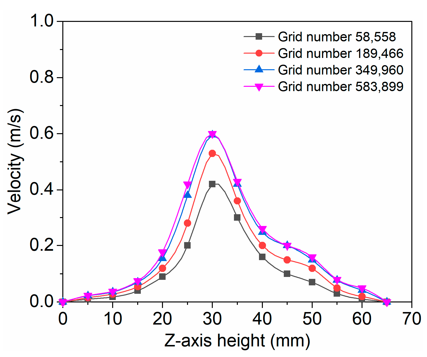
In CFD numerical simulation, grid independence verification serves as the foundation of the simulation. When the excitation parameters are set to a frequency of 60 Hz and an amplitude of 4 mm, the velocity curve at various positions on the central axis under four different grid types is illustrated in Figure 3. The results indicate that there are no significant changes when the grid number increases from 349,960 to 583,899. Based on the consideration of the accuracy and the computational time, a grid number of 349,960 is used hereafter. The specific mesh parameters of the mesh model used in CFD simulations are presented in Figure 2b.
For vibration mixing, it is observed that the vibration Reynolds number R e v = ρ A ω D / μ is always less than 200 within the considered frequency and amplitude range. Therefore, the flow remains laminar under all unsteady conditions [42]. ANSYS Fluent is used to solve the computational model, a separate pressure-based solver is selected [41], and the pressure–velocity coupling scheme is PISO. In order to avoid failure of the solution due to excessive Courant number, a variable time-stepping scheme with a maximum time step of 5 × 10⁻⁴ s and a minimum time step of 10−5 s is adopted. In addition, the Courant number is set to 1.

2.3. Evaluation of Mixing Uniformity

In order to evaluate the uniformity of the mixing of the particle phase and the liquid phase, the liquid phase area in the YZ plane and the XZ plane, aligned with the container’s axis, are selected. The particle dispersion uniformity (Sp), which serves as an index for evaluating mixing uniformity, is determined by calculating the ratio of the standard deviation of particle mass concentration in the liquid phase area during mixing (σc) to the standard deviation of particle concentration in the liquid phase area when the particles and liquid phase are completely separated (σ0). When the value is 1, it means that there is no mixing at all. The smaller the value, the better the uniformity of the mixtures. The calculation formula is given below [43]:
S p = σ c σ 0 = E ( c ( x ) c ¯ ) 2 E c 0 ( x ) c 0 ¯ 2
In the formula, E (·) represents the expectation operator, while c(x) and c ¯ denote the particle mass concentration at a certain position x in the liquid phase region and the average particle mass concentration in the liquid phase region at a certain time in the mixing process, respectively. In addition, c0(x) and   c 0 ¯   represent the particle mass concentration at a certain position x in the liquid phase region and the average particle mass concentration in the liquid phase region when the particle and the liquid phase is completely separated, respectively.

3. Results and Discussion

3.1. Model Validation

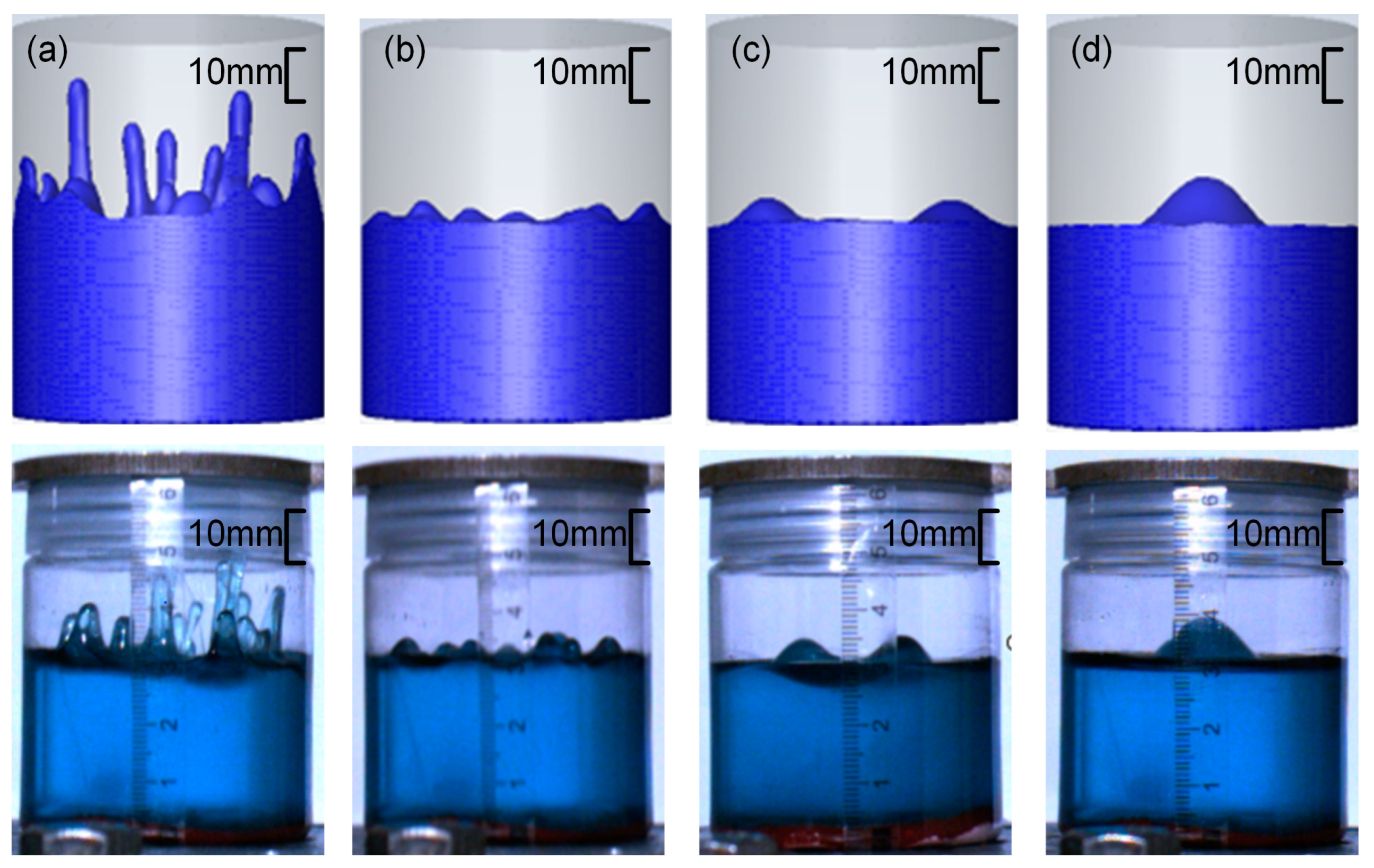
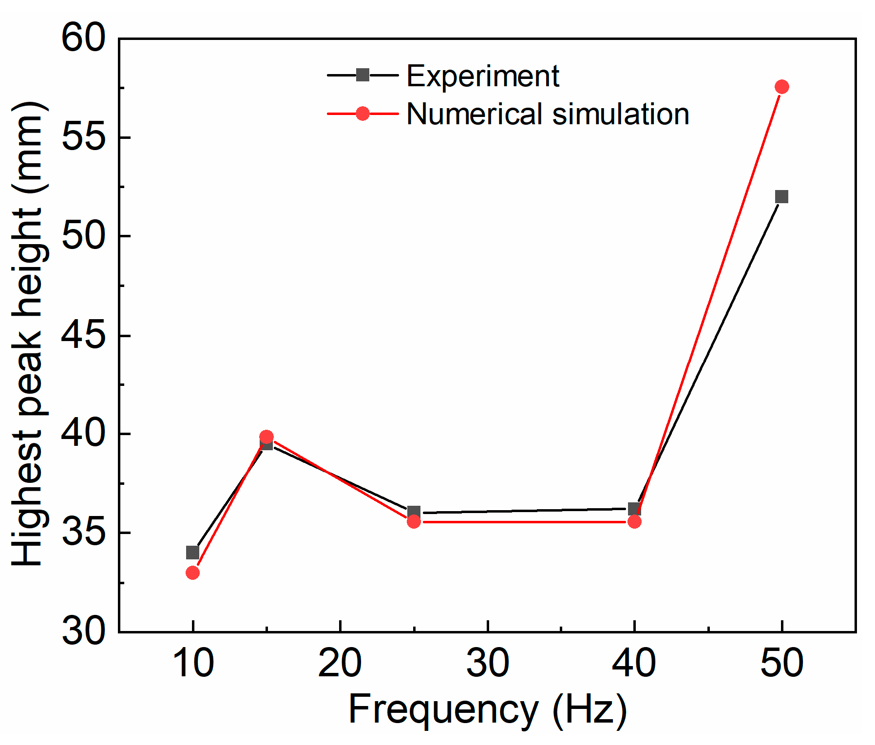
To evaluate the accuracy of the CFD model, the solid particles and glycerin marked with blue tracer were used as experimental materials with an amplitude of 2.5 mm and different frequencies. A high-speed camera captured the motion of the liquid phase inside the container at a rate of 790 frames per second and transmitted the image data to a computer for image analysis. A transparent tape ruler was attached to the mixing container to observe the surface wave size and peak height at the liquid level during the mixing process. The test results and the numerical simulation results were compared in Figure 4 and Figure 5. When the excitation frequency was very low, the high-viscosity liquid in the container remained nearly static. As the vibration frequency increased, the number of wave peaks produced by the fluctuations of the liquid surface increased and the diameter of the wave peaks decreased, indicating that the parameters exerted a significant impact on the flow characteristics. The results showed that the experimental liquid level waveform and the highest wave height were in excellent agreement with the numerical simulation results, which proved the accuracy of the simulation results.
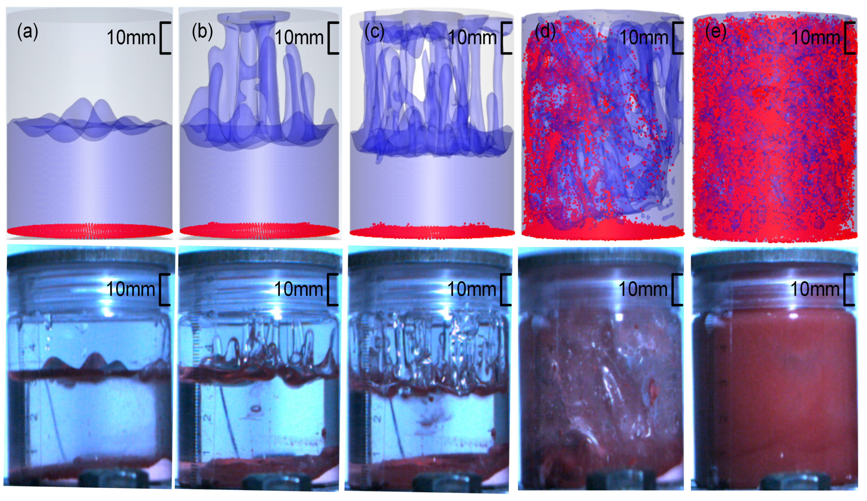
Furthermore, colorless glycerin and red sand particles were used as experimental materials, and the gas–liquid free surface and particle distribution obtained by simulation and experiment at different times with a vibration excitation frequency of 60 Hz and an amplitude of 4 mm were recorded, as depicted in Figure 6. The experimental results indicated that in the initial stage of mixing, particles gathered at the bottom of the container. However, as the gas–liquid free surface moved near the bottom of the container, the violently moving liquid phase moved and dispersed the particles to the entire field until they were mixed evenly. The experimental results of the gas–liquid free surface and particle distribution exhibited a strong agreement with the numerical simulation results, thereby validating the accuracy of the numerical simulations.

3.2. Flow Field Characteristics of High-Viscosity Fluid Excited by Acoustic Vibration

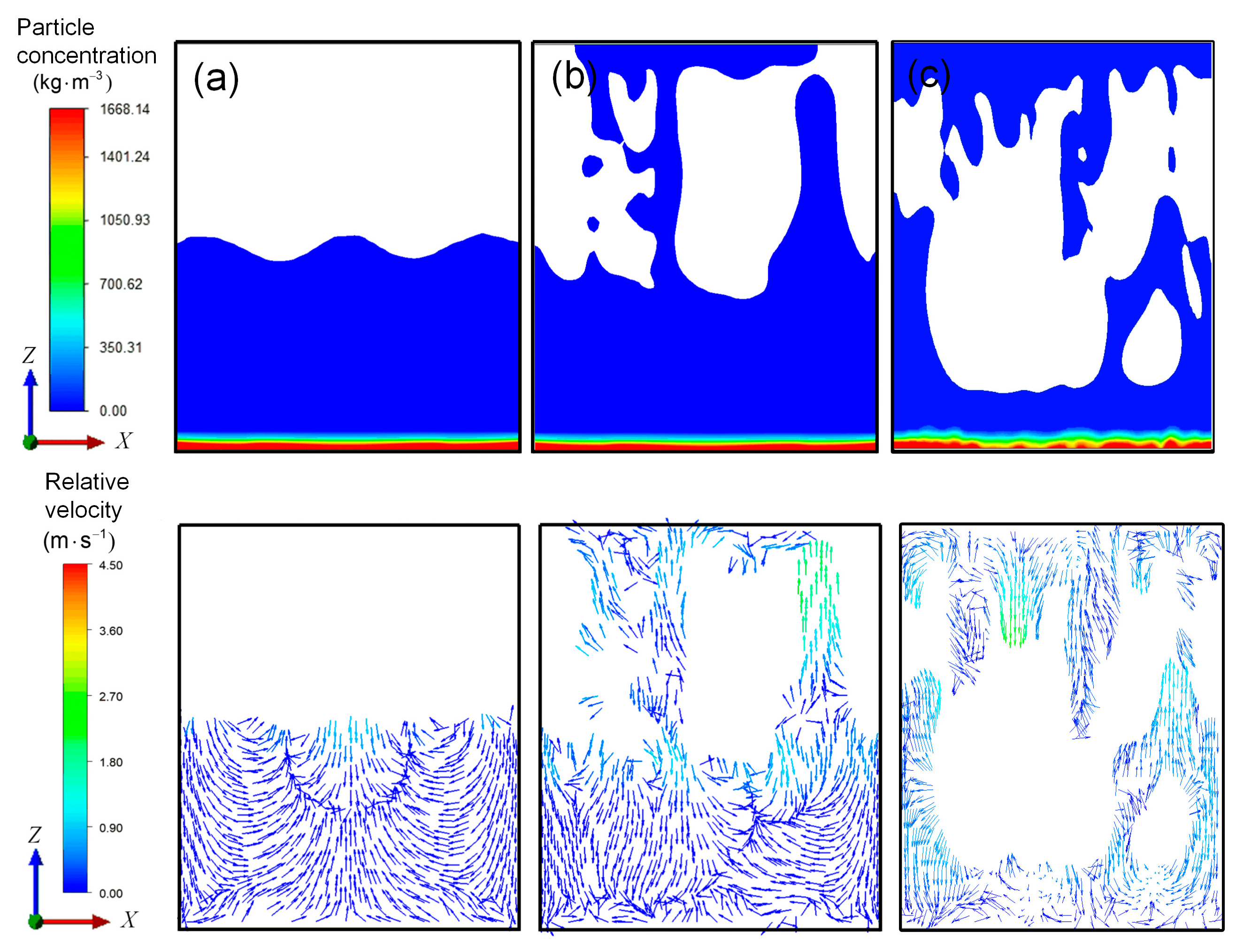
The vibration was initiated at t = 0, when the fluid was at rest. After subjecting the container to vertical vibrations, different flow regimes were observed depending on the intensity of the vibration. Three typical particle-concentration fields and the liquid velocity field relative to the mixing container are shown in Figure 7. When the vibration intensity is low, the liquid level almost does not fluctuate. The flow area is mainly concentrated near the liquid level, and the velocity of the liquid phase at the bottom of the container is low. Consequently, a large number of sand particles remain at the bottom of the container and cannot be evenly dispersed in the liquid phase, and the particle phase and liquid phase are completely separated, as exhibited in Figure 7a.
When the vibration intensity increases, the fluctuation of the liquid level becomes larger and the relative velocity of the fluid near the liquid level increases, which is the main flow region of the liquid phase. There are obvious Faraday waves and other phenomena that contribute to enhance the contact area of the gas and liquid phases and accelerate the mass transfer between them. However, outside the flow region, the fluid below still exhibits a low velocity relative to the container. The fluid at the bottom of the container remains relatively stagnant, which leads to a “dead zone” for mixing. Even if the operation time is prolonged, the particle phase collected in this region will not disperse, as shown in Figure 7b. In both cases, sand particles and the high-viscosity glycerin cannot be mixed quickly and uniformly.
When the vibration intensity increases to a certain threshold, the liquid phase in the mixing container moves violently in the entire field, driving the fluid to move relatively from top to bottom, and the materials in the bottom are taken away from the bottom of the container. As shown in Figure 7c, the high-viscosity glycerin moves and disperses with the sand particles throughout the container, quickly and efficiently promoting the full-field mixing of the glycerin and sand particles.
From the plot of the particle concentration field and the vector plot of the relative velocity field under different vibration parameters, it becomes evident that the intensity of the vibration must reach a certain threshold to achieve the mixing of the solid–liquid phases with high viscosity. Once the threshold value is reached, full-field mixing can be achieved in a very short time.

3.3. Characteristic Analysis of the Full-Field Mixing

Full-field mixing is the premise of uniform mixing and is essential in actual production mixing. Figure 8 shows the uniformity of particle dispersion at different times with a vibration excitation frequency of 60 Hz and an amplitude of 4 mm. According to Figure 8, the mixing process of the highly viscous liquid and particle phase can be divided into three stages, namely, T1—the liquid level fluctuation stage, T2—the development stage, and T3—the stability stage.
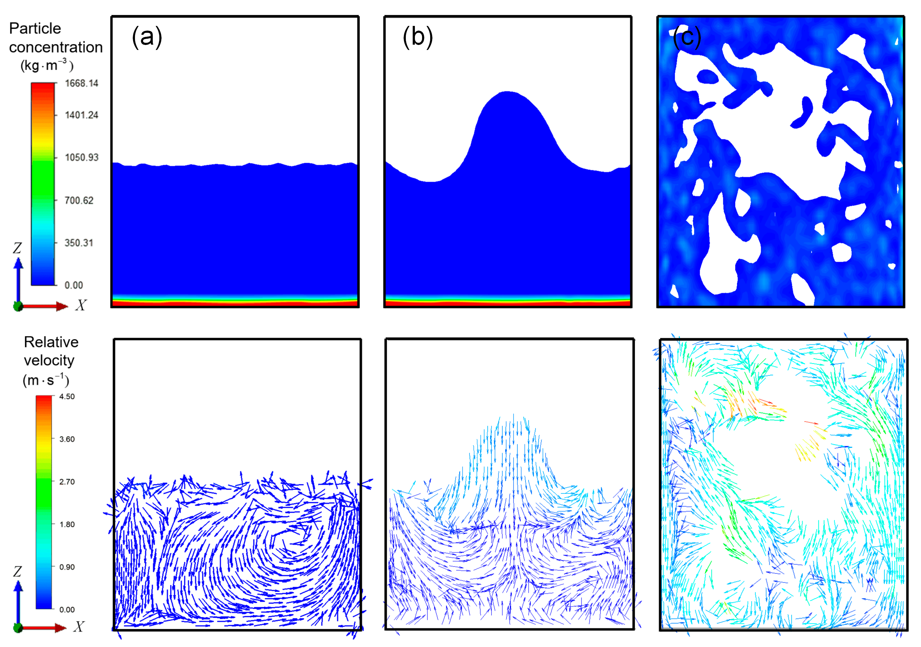
In the initial stage of liquid level fluctuation (T1), it can be seen from Figure 8 that the uniformity of particle dispersion decreases slowly. The particle concentration field and the liquid-phase relative velocity vector field in the XZ section of the mixing container at this stage are shown in Figure 9a. From the figure, the gas–liquid interface starts to fluctuate from the static state, and the fluctuation amplitude gradually increases, resulting in liquid column sputtering. The violent movement area gradually moves from the top of the mixing container to the bottom. The mixing dead zone gradually decreases, but the relative velocity of fluid around the particle deposition area at the bottom is still low. In this stage, the energy absorbed by the liquid phase is not much because of the operation time limit. The velocity of the liquid phase in the entire field is relatively low, resulting in no convection in the entire field.
In the stage of T1, the flow field in the vessel is dominated by liquid level fluctuation and liquid column sputtering. It can be seen from Figure 9b,c that the liquid column generated at the liquid surface continuously splashes on the upper wall of the container. Due to the effect of surface tension and wall adhesion, the liquid sputtered to the wall of the container shows the characteristics of “sticking to the wall” movement and thus has more time to return to the bottom of the container. Therefore, the lowest part of the liquid level constantly moves to the bottom of the container. In this process, the gas–liquid interface area and the overall velocity of the flow field both increase, improving the fluidity of the liquid phase.
At the same time, from the perspective of the flow field, the flow field inside the liquid phase is affected by the violent movement of the liquid surface, resulting in the formation of several vortices in different flow directions. They meet and collide near the bottom of the container, causing the fluid flow at the bottom of the container to become more complex and the direction of the velocity vector to become very chaotic. In fact, this chaotic flow leads to the dispersion of particles in the high-viscosity liquid. However, the improvement in the liquid phase fluidity is from the top to the bottom, and the flow velocity of the liquid phase near the bottom particles is relatively small throughout this stage, resulting in low mixing efficiency of particles and a high-viscosity liquid phase.
In the development stage (T2), it can be seen from Figure 8 that the particle dispersion uniformity decreases rapidly, indicating that the particles are rapidly dispersed in the liquid phase. This can be attributed to the violent and disorderly movement of the liquid phase throughout the entire field, as well as the movement of the gas–liquid free surface across the entire field. The overall speed of the liquid phase is high and the force on the particles is strong, so the particles are bound and dispersed to the entire field.
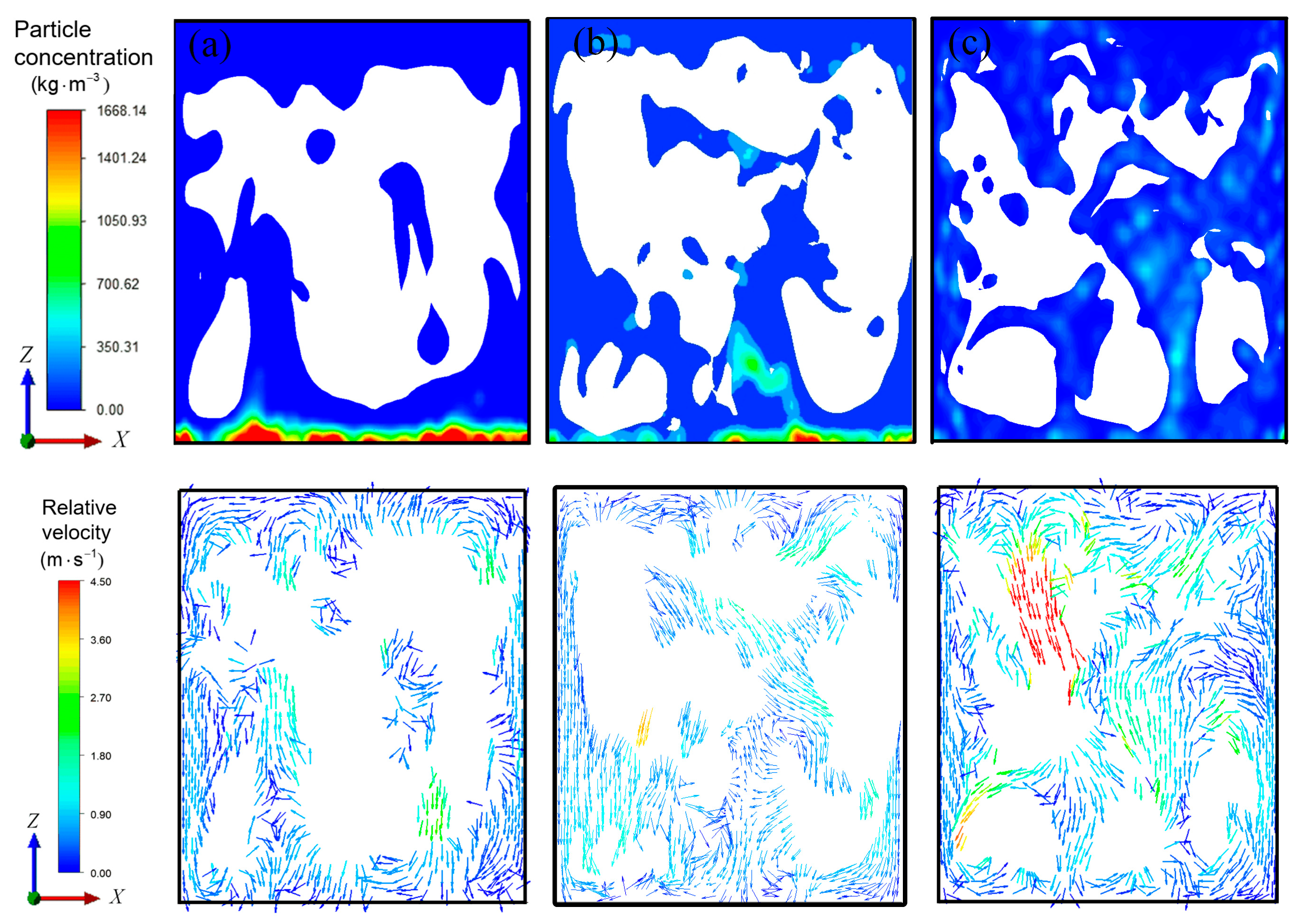
In the stage of T2, the liquid phase moves violently throughout the field and its flow characteristics are complex, but still show certain rules as a whole. Figure 10a–c illustrate that during this stage, the lowest liquid level has moved near the particles at the bottom of the container. Under the influence of the sputtering movement of the liquid phase, the particles are bound to move towards the upper part of the container and disperse. At the same time, the liquid phase moving “against the wall” carries the particles from the upper part of the container to the lower part of the container. Both of them together complete the movement cycle of particles between the upper and lower parts of the container.
In this process, the liquid phase near the wall exhibits the characteristics of “sticking to the wall” movement. When it reaches the corner of the container wall, the flow direction changes and a vortex on the wall is formed here. This vortex is responsible for preventing the accumulation of particles in the corner of the container. The movement and deformation of the gas–liquid free surface generate tensile and shear flow fields around gas–liquid free surface, which is a good mixing mechanism. As a result, the velocity of the fluid far from the wall is relatively high and the flow is relatively irregular. The vortex flow is formed in several local areas of the container and causes the particles to disperse rapidly in the liquid phase over the entire field in a very short time.
In the stability stage (T3), the flow field movement characteristics in the mixing container are consistent with those in the development stage, and the liquid phase maintains its vigorous motion throughout the field. However, since the particles have been uniformly dispersed into the liquid phase in the development stage, the particle dispersion uniformity value in this stage is stable at a certain value, as shown in Figure 8.

3.4. Influence of Vibration Parameters on Mixing Efficiency

3.4.1. Influence of Amplitude on Mixing Uniformity

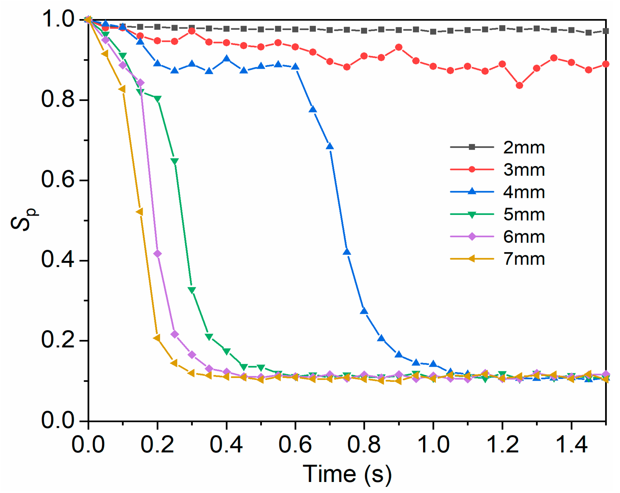
Figure 11 shows the time-varying curve of particle dispersion uniformity SP in the container at 60 Hz and different amplitudes. Under the operating conditions of 2 mm and 3 mm amplitude, the curve decreases slowly and fluctuates around the initial value. This is because the vibration intensity is very low and the liquid phase remains in the liquid level fluctuation stage. This indicates that to achieve uniform mixing of particles and liquid phase with high viscosity, the amplitude must reach a certain threshold where the excitation frequency is constant.
The uniformity of particle dispersion in the working conditions of the amplitude range from 4 mm to 7 mm decreases rapidly and eventually stabilizes around a certain value. This indicates that when the amplitude of excitation exceeds a certain value, the particles can ultimately disperse uniformly in the liquid phase, and the dispersion uniformity is basically the same. Additionally, in order to compare the mixing efficiency under different working conditions, the mixing time is used as an index to describe the mixing efficiency. Mixing time is the time required for the particles to reach uniform dispersion in the liquid phase. In this paper, the mixing time is defined as the moment when the particle dispersion uniformity reaches a final stable value within a range of ±5%. It can be seen from Figure 11 that the values of mixing time corresponding to the amplitude values of 4 mm, 5 mm, 6 mm and 7 mm are 1.05 s, 0.55 s, 0.45 s and 0.3 s, respectively. As the amplitude increases, the mixing time gradually decreases, which shows that increasing the amplitude is an effective means of improving the mixing efficiency.

3.4.2. Influence of Frequency on Mixing Uniformity

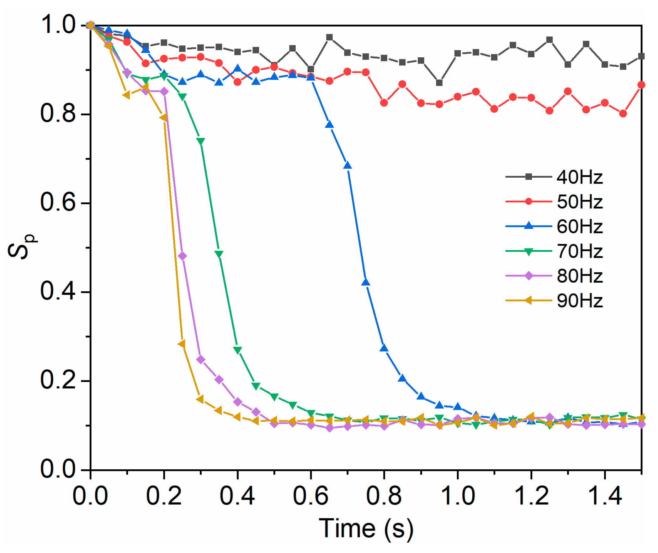
Figure 12 shows the time-varying curve of particle dispersion uniformity SP in the container at different frequencies with an amplitude of 4 mm. From the figure, it can be seen that the uniformity of particle dispersion in working conditions of 40 Hz and 50 Hz fluctuates around the initial value. This suggests that there also exists a threshold limit in the vibration frequency at a certain amplitude in order to achieve uniform mixing of particles in the liquid phase. At the same time, it can be seen from the figure that within 1.2 s, under the working conditions ranging from 60 Hz to 90 Hz, the particle dispersion uniformity decreases rapidly and eventually stabilizes around the same fixed value. As the frequency increases, the mixing time shortens. Specifically, when the frequency increases from 60 Hz to 90 Hz, the mixing time is reduced by 57% from 1.05 s to 0.45 s. This indicates that increasing the vibration intensity with increasing frequency can also improve the mixing efficiency and accelerate the mixing process of particles and high-viscosity liquid.

3.4.3. Influence of Amplitude and Frequency on Mixing Uniformity under Constant Acceleration

Both frequency and amplitude have significant effects on the mixing process. In order to further investigate the effects of frequency and amplitude, the mixing conditions are analyzed under different amplitude and frequency combinations when the acceleration value is 588.6 m/s2. See Table 3 for parameter combinations.
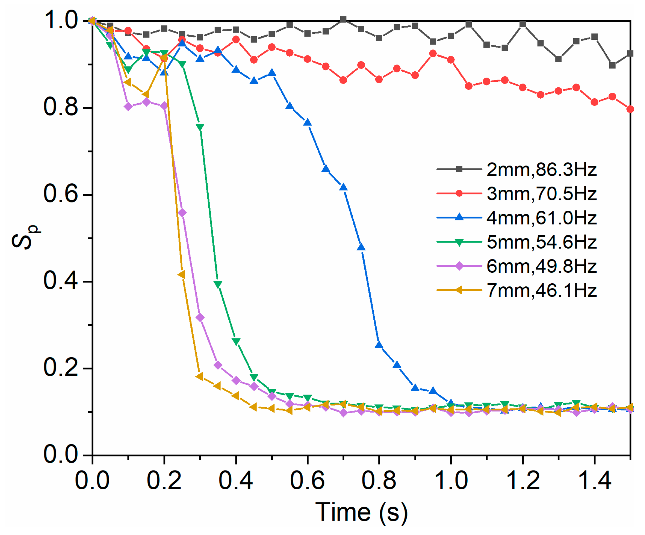
The particle dispersion uniformity Sp at different times under the acceleration of 588.6 m/s2 and the combination of different amplitudes and frequencies are shown in Figure 13. It can be seen from the figure that even if the acceleration value is the same, the mixing effect of particles and high-viscosity liquid is quite different in the combination of different amplitudes and frequencies. Within 1.5 s, the curve decreases slightly in the working conditions of 2 mm and 3 mm amplitudes. This is because the number of waves generated by the liquid level in high-frequency and low-amplitude working conditions is greater, and the energy shared by a single wave is less. It is difficult to overcome the gravity to splash on the upper wall of the container. As a result, the liquid level remains in the fluctuation stage, impeding the uniform mixing of particles and high-viscosity liquid.
However, under the working conditions of the amplitude from 4 mm to 7 mm, the particle dispersion uniformity Sp decreases rapidly and ultimately stabilizes at the constant fixed value, and the mixing time is shortened with the increase in amplitude. When the amplitude increases from 4 mm to 7 mm, the mixing time is reduced from 1 s to 0.45 s, and the mixing time is reduced by 55%. It shows that in the condition of constant acceleration, the mixing efficiency of materials is higher in the condition of low frequency and high amplitude. This is because the low frequency and high amplitude are more likely to enhance the sputtering intensity of the liquid column at the liquid level, increase the movement of the liquid phase in the container, and promote the mixing between the particle phase and the high-viscosity liquid phase.

3.5. Threshold of Vibration Parameters for the Full-Field Mixing

Figure 14 illustrates the correlation between amplitude and frequency for the liquid phase to achieve the critical threshold of full-field flow. The criterion for reaching the threshold is that the mixing process enters the stability stage. The red symbols indicate that full-field mixing can be attained at the corresponding amplitude and frequency, while the blue symbols signify only local mixing. The black dashed line signifies the threshold curve for achieving full-field mixing of the liquid phase. The power law relationship presented on the graph represents the theoretical threshold. If the specific combination of vibration parameters falls above the threshold curve, the vibration promotes complete and uniform flow of the liquid phase. Furthermore, the expression of the threshold curve highlights the significant effect that amplitude values have on the occurrence of full-field flow in the liquid phase. This serves as a valuable reference for assessing the minimum requirements when choosing operating parameters.

4. Conclusions and Future Directions

In this paper, the mixing characteristics of high-viscosity solid–liquid phases under high-intensity acoustic vibration are investigated using a combination of experiments and numerical simulations. The results show that the movement and deformation of the gas–liquid free surface significantly affect the movement of the surrounding liquid phase. With increasing vibration intensity, the gas–liquid free surface experiences liquid level fluctuations, liquid column sputtering, and full-field movement and deformation. The movement and deformation of the gas–liquid free surface substantially promote the mixing process. Throughout the process, the full-field movement and deformation of the gas–liquid free surface are the primary conditions for the rapid mixing of the solid–liquid phases.
Achieving full-field rapid mixing of high-viscosity solid–liquid phases involves a threshold limit on vibration parameters. Increasing the vibration intensity with increasing amplitude or frequency can enhance the intensity of liquid phase movement, and shorten the mixing time. For a given acceleration, the low-frequency and high-amplitude conditions are more likely to stimulate the full-field movement and deformation of the gas–liquid free surface, increasing the mixing efficiency. The findings establish a predictive relationship between amplitude and frequency that enables the determination of optimal mixing conditions. These insights deepen our understanding of the mixing characteristics of high-viscosity materials under acoustic vibration, and have reference values for optimizing the application of high-intensity acoustic vibration in facilitating the efficient mixing of highly viscous materials.
In this study, the influence of temperature field is not taken into account, and the temperature parameter is a crucial index for the mixing process. In the future, the authors plan to establish the heat–fluid coupling model to analyze the temperature change in the mixing process.

Author Contributions

Conceptualization, X.Z. and T.S.; methodology, X.Z.; software, Q.J.; validation, Y.J.; writing—original draft preparation, L.Y.; writing—review and editing, L.Y. and X.Z.; funding acquisition, X.Z. All authors have read and agreed to the published version of the manuscript.

Funding

This work was supported by the National Natural Science Foundation of China (Grant No. 51975226).

Data Availability Statement

Not applicable.

Conflicts of Interest

The authors declare no conflict of interest.

References

  1. Lysien, K.; Lysien, K.; Stolarczyk, A.; Stolarczyk, A.; Jarosz, T.; Jarosz, T. Solid Propellant Formulations: A Review of Recent Progress and Utilized Components. Materials 2021, 14, 6657. [Google Scholar] [CrossRef] [PubMed]
  2. Mason, B.P.; Roland, C.M. Solid Propellants. Rubber Chem. Technol. 2019, 92, 1–24. [Google Scholar] [CrossRef] [Green Version]
  3. Wei, Y.J.; Xu, G.G.; Huang, Q.A.; Liu, X.M. Optimization of HTPB-Bonding System Used for High-Solid-Containing PBX Based on Properties of Materials. Adv. Mater. Res. 2014, 848, 141–145. [Google Scholar] [CrossRef]
  4. Korotkikh, A.G.; Glotov, O.G.; Arkhipov, V.A.; Zarko, V.E.; Kiskin, A.B. Effect of iron and boron ultrafine powders on combustion of aluminized solid propellants. Combust. Flame 2017, 178, 195–204. [Google Scholar] [CrossRef]
  5. Arkhipov, V.A.; Gorbenko, M.V.; Gorbenko, T.I.; Savel Eva, L.A. Effect of ultrafine aluminum on the combustion of composite solid propellants at subatmospheric pressures. Combust. Explos. Shock Waves. 2009, 45, 40–47. [Google Scholar] [CrossRef]
  6. Chaturvedi, S.; Dave, P.N. Solid propellants: AP/HTPB composite propellants. Arab. J. Chem. 2019, 12, 2061–2068. [Google Scholar] [CrossRef] [Green Version]
  7. Mahjub, A.; Mazlan, N.M.; Abdullah, M.Z.; Azam, Q. Design Optimization of Solid Rocket Propulsion: A Survey of Recent Advancements. J. Spacecr. Rocket. 2019, 57, 3–11. [Google Scholar] [CrossRef]
  8. Trache, D.; Klapötke, T.M.; Maiz, L.; Abd-Elghany, M.; DeLuca, L.T. Recent advances in new oxidizers for solid rocket propulsion. Green Chem. 2017, 19, 4711–4736. [Google Scholar] [CrossRef]
  9. Lin, D.; Wei, H.; Song, E.; Ng, B.; He, T.; Dang, L. Experimental and numerical investigation of the scale-up criterion of solid-viscous fluid mixing in a stirred tank. Can. J. Chem. Eng. 2021, 99, S259–S274. [Google Scholar] [CrossRef]
  10. Oberti, S.; Neild, A.; Wah Ng, T. Microfluidic mixing under low frequency vibration. Lab Chip 2009, 9, 1435–1438. [Google Scholar] [CrossRef]
  11. Carlsson, F.; Sen, M.; Löfdahl, L. Fluid mixing induced by vibrating walls. Eur. J. Mech. B. Fluids 2005, 24, 366–378. [Google Scholar] [CrossRef]
  12. Osorio, J.G.; Muzzio, F.J. Evaluation of resonant acoustic mixing performance. Powder Technol. 2015, 278, 46–56. [Google Scholar] [CrossRef]
  13. Zoueshtiagh, F.; Narayanan, R.; Amiroudine, S. Mixing generated by Faraday instability between miscible liquids. Phys. Rev. E 2012, 85, 016326. [Google Scholar] [CrossRef]
  14. Andrews, M.R.; Collet, C.; Wolff, A.; Hollands, C. Resonant Acoustic® Mixing: Processing and Safety. Propellants Explos. Pyrotech. 2019, 45, 77–86. [Google Scholar] [CrossRef]
  15. Vandenberg, A.; Wille, K. Evaluation of resonance acoustic mixing technology using ultra high performance concrete. Constr. Build. Mater. 2018, 164, 716–730. [Google Scholar] [CrossRef]
  16. Davey, R.; Wilgeroth, J.; Burn, A. Processing Studies of Energetic Materials using Resonant Acoustic Mixing Technology. Propellants Explos. Pyrotech. 2019, 45, 1–10. [Google Scholar] [CrossRef]
  17. Osorio, J.G.; Sowrirajan, K.; Muzzio, F.J. Effect of resonant acoustic mixing on pharmaceutical powder blends and tablets. Adv. Powder Technol. 2016, 27, 1141–1148. [Google Scholar] [CrossRef] [Green Version]
  18. Claydon, A.J.; Patil, A.N.; Gaulter, S.; Kister, G.; Gill, P.P. Determination and optimisation of Resonant Acoustic Mixing (RAM) efficiency in Polymer Bonded eXplosive (PBX) processing. Chem. Eng. Process. 2022, 173, 108806. [Google Scholar] [CrossRef]
  19. Bale, S.; Clavin, K.; Sathe, M.; Berrouk, A.S.; Knopf, F.C.; Nandakumar, K. Mixing in oscillating columns: Experimental and numerical studies. Chem. Eng. Sci. 2017, 168, 78–89. [Google Scholar] [CrossRef]
  20. Zhan, X.; Zhibin, S.; Yu, H.; Shen, B.; Shi, T.; Li, X. Characterization of Fluid Mixing in a Closed Container under Horizontal Vibrations. Can. J. Chem. Eng. 2018, 97, 1931–1938. [Google Scholar] [CrossRef]
  21. Khan, I.U.; Guo, R.; Farooq, U.; Adhikari, S.; Zhou, H. Parametric Effects on the Mixing Efficiency of Resonant Acoustic Mixing Technology for High-Viscosity Mixture: A Numerical Study. Processes 2023, 11, 266. [Google Scholar] [CrossRef]
  22. Li, L.; Gu, Z.; Xu, W.; Tan, Y.; Fan, X.; Tan, D. Mixing mass transfer mechanism and dynamic control of gas-liquid-solid multiphase flow based on VOF-DEM coupling. Energy 2023, 272, 127015. [Google Scholar] [CrossRef]
  23. Nemati, M.; Shateri Najaf Abady, A.R.; Toghraie, D.; Karimipour, A. Numerical investigation of the pseudopotential lattice Boltzmann modeling of liquid–vapor for multi-phase flows. Physica A 2018, 489, 65–77. [Google Scholar] [CrossRef]
  24. Pukkella, A.K.; Vysyaraju, R.; Tammishetti, V.; Rai, B.; Subramanian, S. Improved mixing of solid suspensions in stirred tanks with interface baffles: CFD simulation and experimental validation. Chem. Eng. J. 2019, 358, 621–633. [Google Scholar] [CrossRef]
  25. Li, W.; Zhou, Q.; Yin, G.; Ong, M.C.; Li, G.; Han, F. Experimental Investigation and Numerical Modeling of Two-Phase Flow Development and Flow-Induced Vibration of a Multi-Plane Subsea Jumper. J. Mar. Sci. Eng. 2022, 10, 1334. [Google Scholar] [CrossRef]
  26. Garoosi, F.; Hooman, K. Numerical simulation of multiphase flows using an enhanced Volume-of-Fluid (VOF) method. Int. J. Mech. Sci. 2022, 215, 106956. [Google Scholar] [CrossRef]
  27. Gu, D.; Cheng, C.; Liu, Z.; Wang, Y. Numerical simulation of solid-liquid mixing characteristics in a stirred tank with fractal impellers. Adv. Powder Technol. 2019, 30, 2126–2138. [Google Scholar] [CrossRef]
  28. Leporini, M.; Marchetti, B.; Corvaro, F.; di Giovine, G.; Polonara, F.; Terenzi, A. Sand transport in multiphase flow mixtures in a horizontal pipeline: An experimental investigation. Petroleum 2019, 5, 161–170. [Google Scholar] [CrossRef]
  29. Toghraie, D.; Mashayekhi, R.; Arasteh, H.; Sheykhi, S.; Niknejadi, M.; Chamkha, A.J. Two-phase investigation of water-Al2O3 nanofluid in a micro concentric annulus under non-uniform heat flux boundary conditions. Int. J. Numer. Methods Heat Fluid Flow 2019, 30, 1795–1814. [Google Scholar] [CrossRef]
  30. Sengia, J.; James, A.; Singh, R.; Bale, S. Size effect of oscillating columns on mixing: A CFD study. Eur. J. Mech. B. Fluids 2019, 77, 230–238. [Google Scholar] [CrossRef]
  31. Valha, J.; Lewis, J.; Kubie, J. A numerical study of the behaviour of a gas–liquid interface subjected to periodic vertical motion. Int. J. Numer. Methods Fluids 2002, 40, 697–721. [Google Scholar] [CrossRef]
  32. Wang, C.; Ji, C.; Zou, J. Simulation and experiment on transitional behaviours of multiphase flow in a hydrocyclone. Can. J. Chem. Eng. 2015, 93, 1802–1811. [Google Scholar] [CrossRef]
  33. Wang, R.; Jia, S.; He, Z. Numerical Investigation on the Effects of Impeller Structures in Hot Metal Desulfurization Processes by Mechanical Stirring. Metals 2022, 12, 229. [Google Scholar] [CrossRef]
  34. Cong, D.; Jian-Zhong, L.; Zhen-Yu, H.; Jun-Hu, Z.; Ke-Fa, C. VOF Method for Impinging-Jet Atomizers. Energy Fuels 2010, 24, 451–455. [Google Scholar] [CrossRef]
  35. Hirt, C.W.; Nichols, B.D. Volume of fluid (VOF) method for the dynamics of free boundaries. J. Comput. Phys. 1981, 39, 201–225. [Google Scholar] [CrossRef]
  36. Brackbill, J.U.; Kothe, D.B.; Zemach, C. A continuum method for modeling surface tension. J. Comput. Phys. 1992, 100, 335–354. [Google Scholar] [CrossRef]
  37. Yao, X.; Zhang, F.; Wang, Z.; Zhang, W. Numerical Modeling of Capillary Flows in a Non-Uniform Cross-Sectional Cavity Basedon VOF and CSF. Semicond. Technol. 2011, 36, 169–172. [Google Scholar] [CrossRef]
  38. Zahari, N.M.; Zawawi, M.H.; Sidek, L.M.; Mohamad, D.; Itam, Z.; Ramli, M.Z.; Syamsir, A.; Abas, A.; Rashid, M. Introduction of discrete phase model (DPM) in fluid flow: A review. AIP Conf. Proc. 2018, 2030, 020234. [Google Scholar] [CrossRef]
  39. Kharoua, N.; AlShehhi, M.; Khezzar, L. Prediction of Black Powder distribution in junctions using the Discrete Phase Model. Powder Technol. 2015, 286, 202–211. [Google Scholar] [CrossRef]
  40. Morel, C. Interfacial Forces and Momentum Exchange Closure. In Mathematical Modeling of Disperse Two-Phase Flows; Fluid Mechanics and Its Applications; Springer: Cham, Switzerland, 2015; Volume 114, pp. 159–191. [Google Scholar] [CrossRef]
  41. Zhu, S.; Xiaopeng, W.; Chen, S.; Xu, X. Simulation of dispersion characteristics of resonant acoustic mixing with low solid content of powder. Chem. Ind. Eng. Prog. 2019, 38, 4414–4422. [Google Scholar] [CrossRef]
  42. Tian, S.; Barigou, M. An improved vibration technique for enhancing temperature uniformity and heat transfer in viscous fluid flow. Chem. Eng. Sci. 2015, 123, 609–619. [Google Scholar] [CrossRef] [Green Version]
  43. Shi, Y.; Jiang, P.; Wang, F.; Zhou, S. Experimental Study on Mixing Uniformity of Injection On-Line Mixer of Crop Protection Equipment. Int. J. Heat Technol. 2021, 39, 1143–1152. [Google Scholar] [CrossRef]
Figure 1. Acoustic vibration mixing system.
Processes 11 02367 g001
Figure 2. Boundary conditions (a) and mesh model (b).
Processes 11 02367 g002
Figure 3. The velocity at different positions on the central axis under different grid types.
Processes 11 02367 g003
Figure 4. Simulated liquid level fluctuation (upper part) and experimental liquid level fluctuation (lower part) with amplitude of 2.5 mm and different frequencies. (a) f = 50 Hz. (b) f = 40 Hz. (c) f = 25 Hz. (d) f = 15 Hz.
Processes 11 02367 g004
Figure 5. Comparison of the highest peak height of the liquid level between experiment and numerical simulation under the amplitude of 2.5 mm and different frequencies.
Processes 11 02367 g005
Figure 6. Simulation (upper part) and experiment (lower part) of gas–liquid free surface and particle distribution at different times. (a) t = 0.05 s. (b) t = 0.3 s. (c) t = 0.5 s. (d) t = 0.7 s. (e) t = 1.0 s.
Processes 11 02367 g006
Figure 7. Three typical cloud diagrams of particle concentration field (upper part) and vector diagram of relative velocity field (lower part) under vibration excitation. (a) f = 5 Hz, A = 4 mm, (b) f = 20 Hz, A = 4 mm, (c) f = 60 Hz, A = 4 mm.
Processes 11 02367 g007
Figure 8. Particle dispersion uniformity at different times in the whole mixing flow field.
Processes 11 02367 g008
Figure 9. Cloud diagram of particle concentration field (upper part) and vector diagram of velocity field (lower part) in the mixing container at different times of the whole mixing flow field. (a) t = 0.1 s, (b) t = 0.2 s, (c) t = 0.4 s.
Processes 11 02367 g009
Figure 10. Cloud diagram of particle concentration field (upper part) and vector diagram of velocity field (lower part) in the mixing container at different times of the whole mixing flow field. (a) t = 0.6 s, (b) t = 0.7 s, (c) t = 0.8 s.
Processes 11 02367 g010
Figure 11. Particle dispersion uniformity at different times under different amplitudes at 60 Hz.
Processes 11 02367 g011
Figure 12. Particle dispersion uniformity at different times under different frequencies with an amplitude of 4 mm.
Processes 11 02367 g012
Figure 13. Particle dispersion uniformity at different amplitudes and frequencies at different times under acceleration of 588.6 m/s2.
Processes 11 02367 g013
Figure 14. The amplitude-frequency relationship for the liquid phase to reach the threshold of full-field mixing.
Processes 11 02367 g014
Table 1. Summary of the literature on multiphase flow mixing.
AuthorsResearch ThemeKey Finding
Osorio et al. [17]Mixing characteristics of powder by RAM experimentPowder and tablet properties were significantly affected by acceleration, mixing time and total energy input.
Claydon et al. [18]The effects of process parameters on RAM efficiencyPartial vacuum application without degassing is beneficial for mixing.
Bale et al. [19]Free surface stability when mixing in an oscillating columnThe mixing time is highly nonlinear with respect to the vibration frequency.
Zhan et al. [20]Two miscible high-viscosity liquids under vertical vibrationFluid injection can promote the mixing of the two liquids.
Khan et al. [21]Parametric effects on the mixing efficiency of RAM technologyAmplitude and frequency both have significant influences on the mixing efficiency of the RAM process.
Li et al. [22]Mixing mass transfer mechanism of gas–liquid–solid multiphase flowThe appropriate inflation rate can improve particle suspension effects and promote interphase mixing mass transfer.
Nemati et al. [23]Modeling of liquid–vapor for multi-phase flowsThe scheme for the interparticle interaction force term, as well as the force term incorporation method, matters to achieve more accurate and stable results.
Pukkella et al. [24]Mixing of solid suspensions in stirred tanksThe effect of the novel interface baffle design on the mixing uniformity in solid–liquid suspensions is explored.
Li et al. [25]Two-phase flow development and flow-induced vibrationVibration amplitudes are highly related to the gas content rate and mixing velocity.
Garoosi and Hooman [26]Numerical simulation of multiphase flows using an enhanced VOF methodThe proposed model has robust convergence behavior in strongly coupled multiphysics problems.
Gu et al. [27]CFD simulation of solid–liquid mixing characteristics in a stirred tank Larger particle diameter and higher initial solid particle loading resulted in less homogenous distribution of solid particles.
Leporini et al. [28]Sand transport in multiphase flow mixturesVariation of the sand concentration and particle size in air–water–sand flow causes a change in sand deposition characteristics.
Toghraie et al. [29]Numerical study of convective heat transfer using two-phase mixture modelThe nanofluid in a micro concentric annulus and its hydro-thermal effects are simulated.
Table 2. Physical properties of materials.
ParametersValues
Density of glycerin (kg·m−3)1260
Viscosity of glycerin (kg·m−1·s−1)0.8
Density of air (kg·m−3)1.225
Viscosity of air (kg·m−1·s−1)1.79 × 10⁻⁵
Surface tension between air and glycerin (N·m−1)0.063
Density of sand (kg·m−3)2650
Particle size of sand (m)6.3 × 10⁻⁵
Table 3. Combinations under different amplitudes and frequencies at a certain peak acceleration.
ConditionAcceleration (m/s2)Amplitude (mm)Frequency (Hz)
a588.6286.3
b588.6370.5
c588.6461.0
d588.6554.6.
e588.6649.8
f588.6746.1
Disclaimer/Publisher’s Note: The statements, opinions and data contained in all publications are solely those of the individual author(s) and contributor(s) and not of MDPI and/or the editor(s). MDPI and/or the editor(s) disclaim responsibility for any injury to people or property resulting from any ideas, methods, instructions or products referred to in the content.