Article

Study on the Influence of Fluid Pulsation on Hydraulic Impactor Performance in Drilling Engineering

Geosteering & Logging Research Institute, Sinopec Matrix Corporation, Qingdao 266071, China
*
Author to whom correspondence should be addressed.
Processes 2023, 11(8), 2392; https://doi.org/10.3390/pr11082392
Submission received: 20 June 2023 / Revised: 20 July 2023 / Accepted: 31 July 2023 / Published: 9 August 2023
(This article belongs to the Special Issue Study of Multiphase Flow and Its Application in Petroleum Engineering)

Abstract

:
The combination of the hydraulic impactor and positive displacement motor (PDM) is becoming more and more popular in drilling engineering. However, the negatives of the PDM on the impactor cannot be ignored. To improve the performance of the technique, the influence of fluid pulsation from the PDM on the hydraulic impactor was studied first; then, the structure of the impactor was optimized to improve its impact force; finally, field tests were carried out in 2 wells in the shallow formation. The results indicate that the fluid fluctuation generated in the PDM can restrain the performance of the impactor, and that the impact force can be increased by 24.4% to 28.6% through the optimization of design. Field tests show that this technique can further improve the drilling efficiency and rotating stability of the polycrystalline diamond compact bit, and that the rate of penetration and bit footage increase by 32.5% and 34.6%, respectively. In the study, the effect of inlet fluid fluctuation on the performance of the hydraulic impactor was studied using the computational fluid dynamics method. This is unlike other studies that have mostly considered the inlet fluid as a steady flow. Furthermore, the performance of the combine used of the impactor and PDM can be improved through structural optimization.

1. Introduction

The drilling cost is the key to the investment efficiency of oil and gas exploration and development. There are many factors affecting the drilling cost, among which the time of the drilling cycle plays a pivotal role in the total drilling cost. Improving the rate of penetration (ROP) is the most effective way to shorten the time of the whole drilling cycle. However, it is always a challenge to drill for oil and gas in complex formations of onshore deep wells [1,2,3].
Generally, the vertical depth of deep wells is over 6000 m, and that of ultra-deep wells is over 8000 m. Western China is one of the main areas in the world where deep and ultra-deep wells are distributed. These range in depth from 7300 to 8600 m [4,5]. Although the rock of the Triassic and its upper strata are less difficult to drill, the average section is over 3000 m. Various formations are encountered during the drilling process; therefore, the reliability and service life of drilling tools are required to be high. In the past, engineers preferred positive displacement motor (PDM) for shallow drilling, but the actual drilling situation shows that the use of the PDM to complete the drilling section often takes 2–3 times exceeding the design expectations. In order to further shorten drilling time, high-efficiency drilling techniques need to be developed [6].
The PDM method is one of the revolutionary technologies in the petroleum industry, and it is a mature technology in conventional drilling [7]. PDM is driven by drilling fluid, which is powered by the continuous high- and low-pressure conversion between the stator and the rotor. The drilling fluid flows in the pressure cavities of the PDM to drive the bit to rotate; therefore, there is a certain fluctuation in the outlet flow of the PDM that affects the working characteristics of the other tools.
The PDM increases the rotary speed of the bit to a fairly high level, thereby improving the cutting efficiency of the bit. Besides, sufficient cutting depth is also needed to achieve high rock-breaking efficiency. The most effective way to increase the cutting depth of the bit cutter is to apply pressure to the bit, with the exception of increasing the weight of bit (WOB). The relationship between cutting force and rock breaking was studied Based on the theory of the metal cutting model [8]. Researchers [9,10] found that the cutting depth increases obviously with the increase in the impact load. A linear relationship was detected between the forces and the cutting depth of shallow cutting. When the cutting depth is greater than a certain value, the rock-breaking speed increases rapidly and enters into a different mode. Studies [11,12,13] of rock fracture mechanics show that impact loads can improve the rate of crack growth, which is the important difference between an impact load and a static load. The impact load can easily enter into the second rock-breaking mode, which is the rapid rock-breaking mode. Therefore, using hydraulic energy to directly drive downhole tools to emit periodic axial impact force without improving the capability of surface equipment is an effective way to improve drilling performance.
The new drilling technology [14,15,16,17,18,19,20], which combines the drill bit, PDM, and hydraulic impactor, was put forward from two aspects of improving bit rotation speed and axial force. Compared with conventional rotary drilling, this technology can increase cutting speed and cutting depth at the same time.
However, the fluid pulsation generated by the PDM has a negative effect on the performance of the impactor. The pressure drop, rotating speed, and torque of the PDM vary with the WOB, which is almost impossible to maintain as a constant in the actual drilling process [21,22,23]. In actual drilling, the WOB and torque are always fluctuating with time. The dynamic monitoring of pressure shows that the fluctuation frequency of the pressure is equal to the product of the rotor rotation frequency, and the pressure fluctuation increases with the increase in the inlet pressure or the output torque of the drill tool. When the impactor is under PDM, the pressure fluctuation at the outlet of the PDM will affect the internal flow of the impactor, changing the impact parameters of the impact drilling tool.
Therefore, we analyzed the influence of the fluid pulsation on the working performance of the downhole impactor, and the force amplitude could be increased by optimizing the structure of the impactor. Firstly, we introduced the structure and working principle of an impactor, as well as some issues that may arise when using it in conjunction with a PDM. Then, we established the fluid domain of the impactor and provided reasonably appropriate boundary conditions. Using the computational fluid dynamics method, we simulated the impact force results at different inlet flow amplitudes and frequencies. We analyzed the impact of the inlet flow on the impactor and subsequently improved the impact performance by optimizing the geometric structure of the impactor. Field tests were carried out in two wells to evaluate the drilling performance by comparing the average ROP and bit footage with adjacent wells in shallow strata. Finally, in Section 5, we presented the conclusions of this study and explored the potential application of this technology in directional wells.

2. Hydraulic Impactor

The hydraulic impactor is mainly composed of an upper sub, a high jet nozzle, a hydraulic hammer, a rollaway nest, and a lower sub. The drilling fluid flows through the nozzle and acts on the upper end of the hammer, generating a periodic high-frequency axial dynamic force. The cutting depth of the polycrystalline diamond compact (PDC) cutter increases because of the axial impact force, and the damaged area of rock increases, and so the broken volume increases. Besides, the impact load can increase the volume of rock fragmentation near the front face of the cutter, resulting in a decrease in the overall strength of the rock.
When the downhole impactor is used with the PDM, the bottom hole assembly (BHA) is usually designed as follows: bit + hydraulic impactor + PDM + drill collar, as shown in Figure 1.
The impact load changed the rock breaking of PDM drilling mode into the combined mode of high-speed cutting and impact fragmentation. The impact load increases the cutting depth and causes an increase in cutting resistance. If the cutting force of the bit is insufficient, it is easy to cause the stick–slip vibration of the bit. When the rotation speed of PDM is too high, the rock impact hole density is low, and the impact depth is shallow, meaning that the rock-breaking efficiency is low. Based on the analysis, the low-rotating-speed and high-torque PDM should be used in combination with downhole percussion tools.

3. Optimization of Hydraulic Impactor

3.1. Numerical Simulation Method

(1)
Numerical model
Fluent was used to simulate the fluctuation of the fluid flowing through the self-excited oscillating cavity with a constant flow velocity and different fluctuating flow velocities. The fluid domain of the force generation mechanism mainly consists of the nozzle domain, oscillation cavity domain, and hammer cavity domain, as shown in Figure 2. In order to save computational time, a two-dimensional structure was used for the simulation, as shown in Figure 3.
(2)
Computational fluid dynamics method
The first step in this method is filtering by dividing all flow variables into large-scale quantities and small-scale quantities. A(x, t) is any instantaneous flow variable, and its large-scale quantity can be represented by a weighted integral over the next physical spatial region.
A ¯ ( x , t ) = G ( | x x | A ( x , t ) ) d V
where, G ( | x x | ) is the filtering function.
The governing equation is as follows:
t ( ρ V i ¯ ) + x j ( ρ V i V j ¯ ) = p ¯ x i + x i ( μ V i ¯ x j ) + τ i j x j
The equation for the instantaneous state is as follows:
ρ t + x j ( ρ V j ¯ ) = 0
The quantity with an overline represents the filtered field variable, where
τ i j = ρ V i V j ¯ + ρ V i V j ¯
The variable τ i j is defined as the subgrid-scale stress (SGS), which represents the influence of small-scale vortex motion on the solved motion equations. The subgrid-scale stress is
τ i j = 2 μ t S i j ¯ 1 3 τ k k δ i j
where μ t is the subgrid-scale turbulent kinetic viscosity, and can be expressed as:
μ t = ( C s Δ ) 2 | S ¯ |
where
S i j ¯ = 1 2 ( V i ¯ x j + V j ¯ x i )
| S ¯ | = ( 2 S i j ¯ S i j ¯ ) 1 / 2
Δ = ( Δ x Δ y Δ z ) 1 / 3
Δ i represents the grid size along the i axis direction, C s is a constant in the subgrid-scale model, C s = 1 π ( 3 2 C K ) 3 / 4 , when CK = 1.5, CS = 0.17.   C K = 1.5 , C s = 0.17 .
In practical applications, the near-wall region is corrected using Equation (10).
C s = C v 0 ( 1 e y / A )
where y is the distance to the nearest wall, A is a semi-empirical constant, and C v 0 is Van Driest constant.
(3)
Inlet fluid fluctuation parameters.
To determine the frequency of inflow fluctuations, the frequency of flow fluctuations at the exit of the PDM is calculated by using the following equation:
fluctuation frequency = rotor rotation frequency × (the number of rotor blades + 1)
Table 1 lists the parameters of a certain type of PDM with an outer diameter of 197mm.
Based on the parameters of the PDM, the fluctuation frequency under the flow rate condition is calculated and presented in Table 2. From Table 2, it can be observed that the fluctuation frequency of the exit flow rate of the PDM is much lower than 500 Hz. Therefore, its response amplitude increases after passing through the impactor. However, the influence of the PDM’s exit flow rate fluctuation on the double-stage oscillation chamber is still not clear. Hence, it is necessary to conduct research in this area.
Several other key pre-processing settings are:
(1)
The properties of drilling fluid in the actual drilling environment were considered in the simulation. Thus, the fluid medium is set as water, but the density is set as 1.2 g/cm3, which belongs to compressible fluid.
(2)
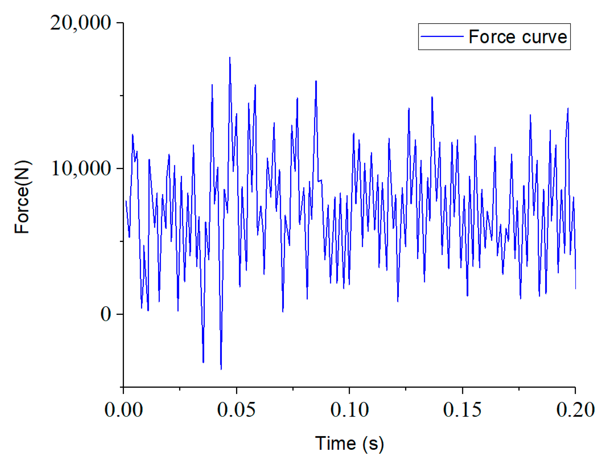
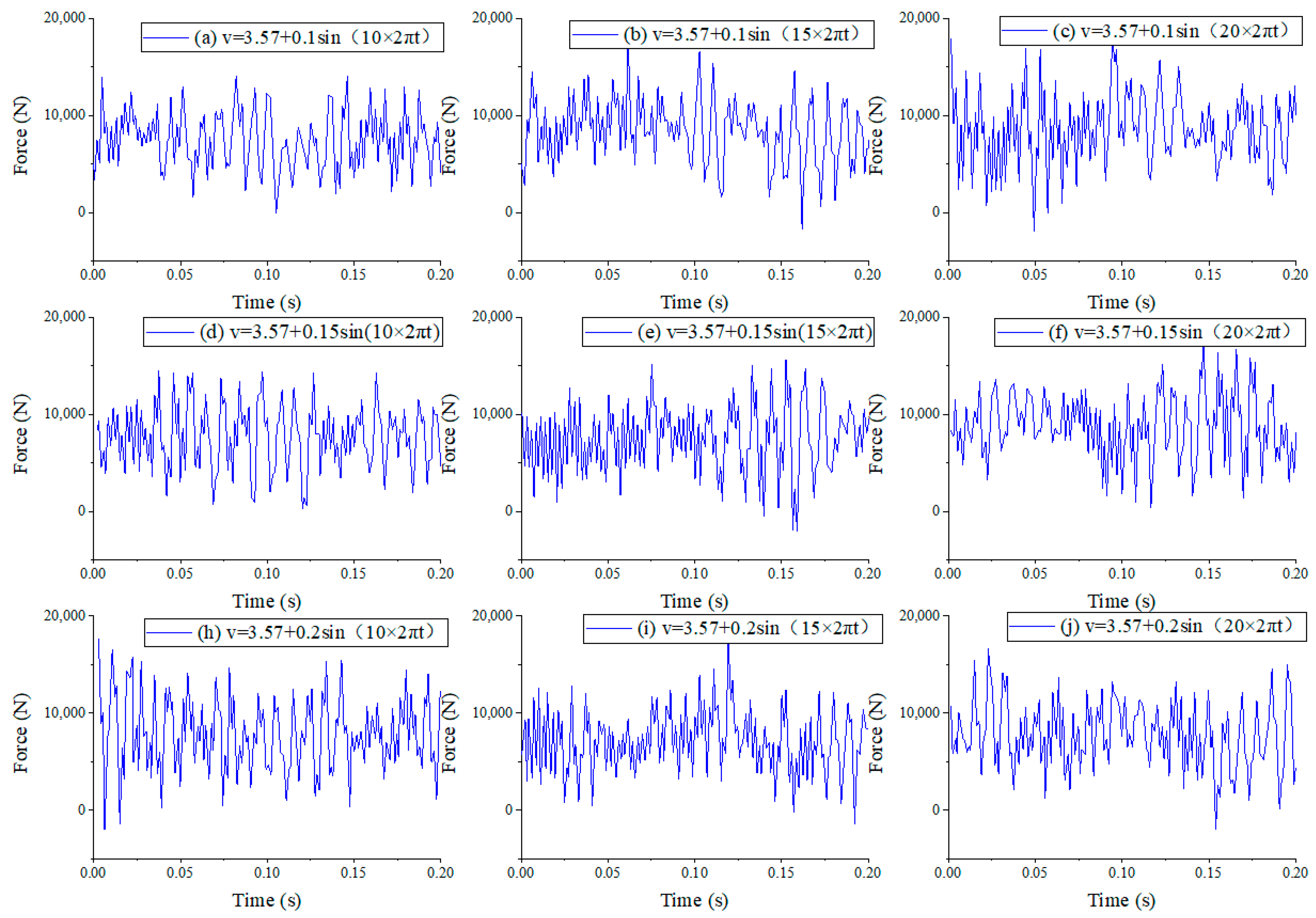
The inlet of the self-oscillation cavity was regarded as the velocity inlet, which simulates the situation with and without considering the PDM. Based on the application experience, the drilling fluid flow rate is 30 L/s, and the velocity condition is 3.57 m/s when the entrance of the self-oscillation cavity is not considered. When the PDM is considered, the entrance velocity is:
v = 3.57 + A s i n ( B · 2 π t )
where 3.57 m/s is the average value of flow velocity; A is the fluctuating amplitude, ranging from 0.1 to 0.2 m/s; and B is the fluctuating frequency, ranging from 10 to 20 Hz.
(3)
The exit boundary of the self-oscillation cavity was set at atmospheric pressure of 101.3 kpa, the fluid wall used the wall function method condition, and the solid surface used the non-slip boundary condition.
(4)
The SIMPLE algorithm was used to solve the equations of pressure and momentum, turbulent dissipation rate, and turbulent kinetic energy. The SIMPLE algorithm, also known as semi-implicit method for pressure-linked equations, was proposed by Patankar and Spalding in 1972. The simplicity, stability, convergence, and versatility of the SIMPLE algorithm make it one of the commonly used methods in computational fluid dynamics.

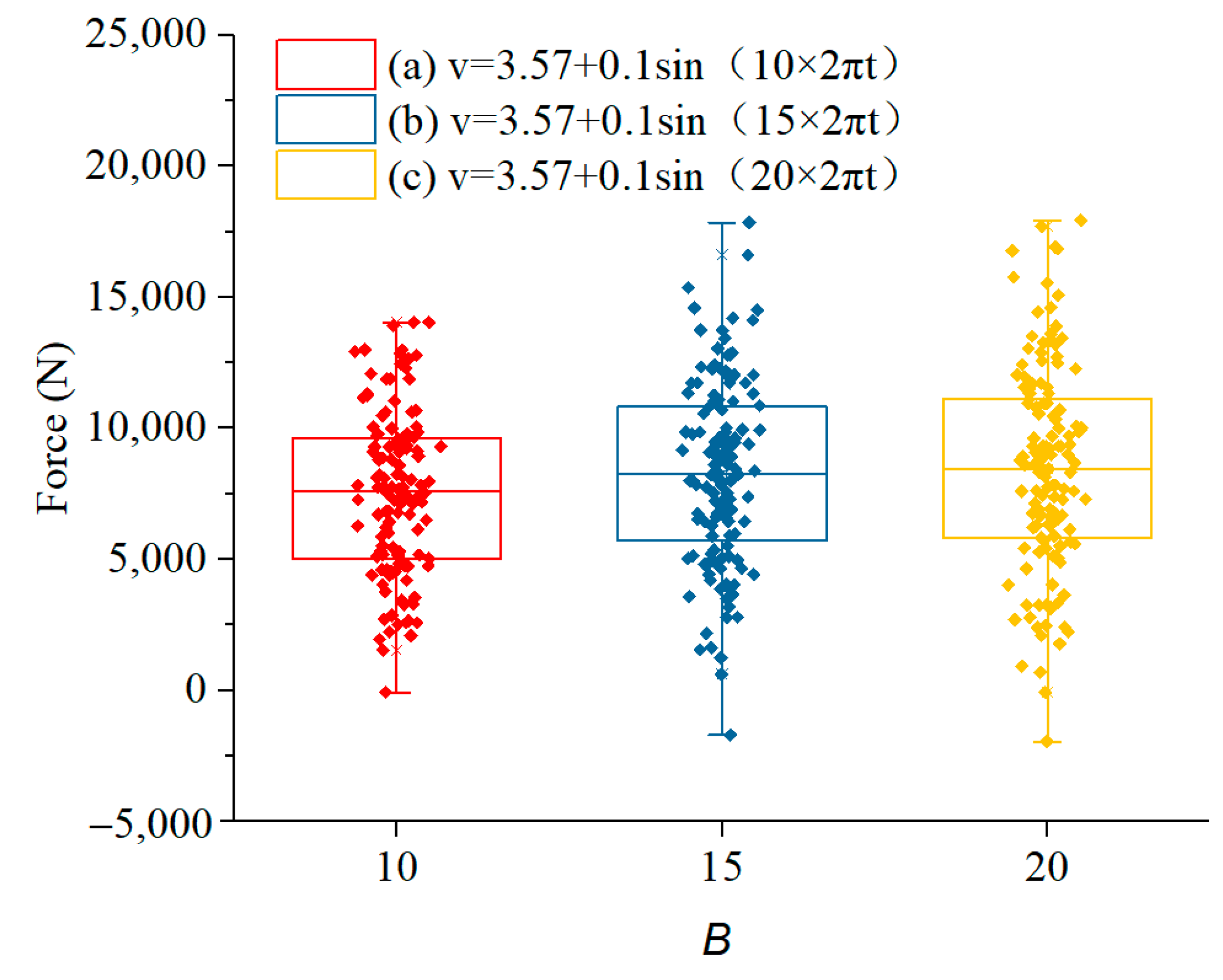
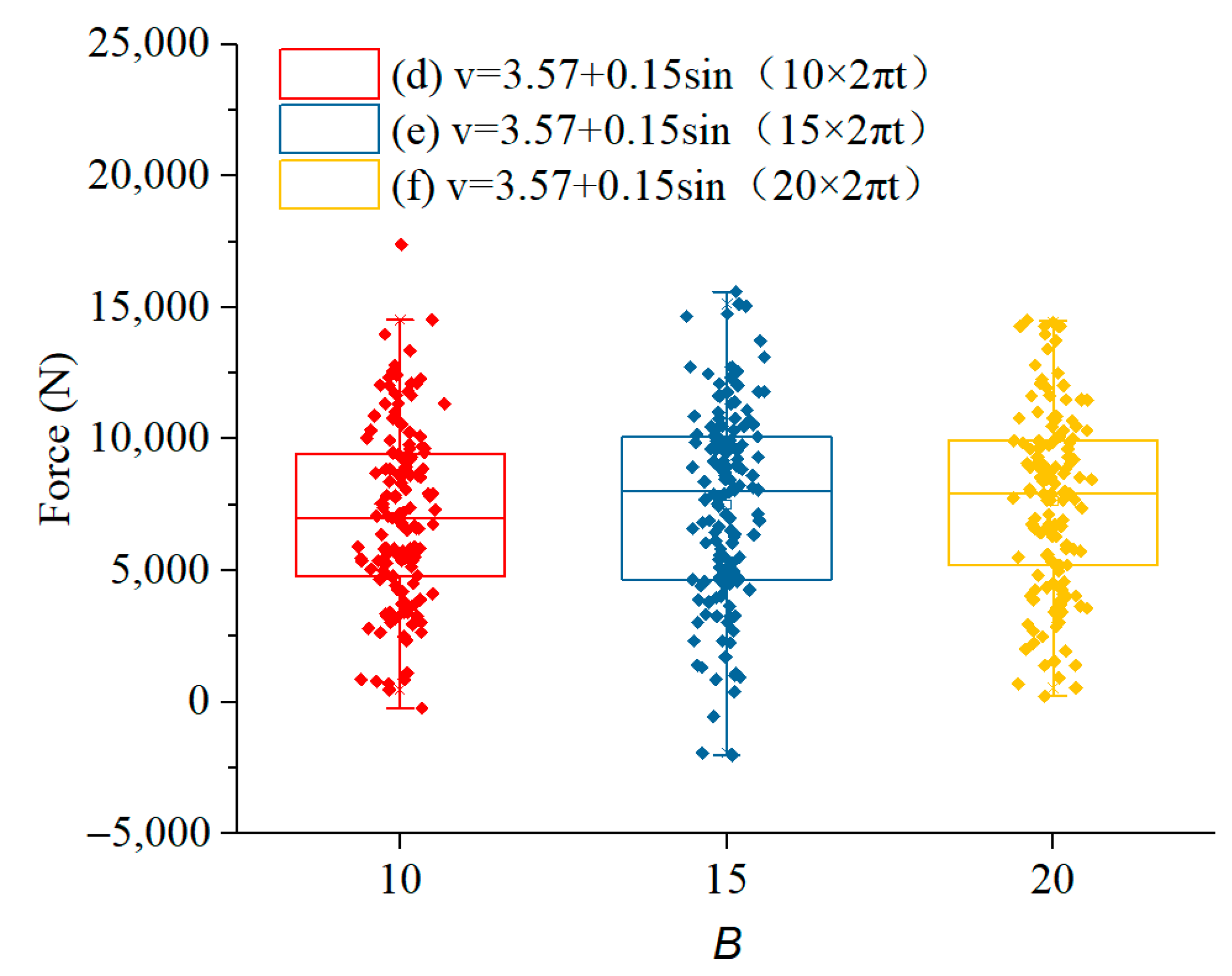
3.2. Influence of Fluid Pulsation

Figure 4 shows the pressure and velocity distribution of the impact generator without fluid pulsation. The fluid flows through the nozzle and generates a high-speed jet, creating a pressure drop between the inlet and outlet of the hammer. The pressure drop can drive the hammer’s upward movement until the hammer outlet is blocked. As the fluid continues to flow in, the pressure continues to rise until the hammer is pushed out. So, reciprocating, the hammer produces periodic motion. In order to study the effect of fluid pulsation, flow simulation was carried out at different flow velocities according to the same simulation method.
First, the force results of the impactor were simulated without any interference from the PDM to serve as a reference for comparison with other simulation results. Figure 5 shows the result of force fluctuation without considering the disturbance of the PDM. The average value of the impact force on the bearing surface is 7181 N, and the fluctuation amplitude of the impact force is 5564 N.
By analyzing the variation of internal pressure inside the impact hammer over time, one can determine the axial motion characteristics of the hammer. When the average value is larger, the impact energy is greater. After a certain period of acceleration, the hammer can achieve a higher initial impact velocity. Similarly, the larger the amplitude of pressure, the greater the energy obtained by the impact hammer. However, the impact force results are stochastic, and this irregular characteristic has a detrimental effect on the stability of the hammer’s motion. Therefore, in the analysis and simulation, it is essential to assess the dispersion of the impact force. We aim to increase the average value and amplitude of the impact force while reducing its dispersion.
Figure 6 shows that the force curves at different inlet velocities display stochastic features. In this case, Figure 6a–c represent the results at different frequencies with a fixed amplitude of 0.1 m/s, and Figure 6d–f as well as Figure 6h–j represent the results at different frequencies with amplitudes of 0.15 m/s and 0.2 m/s, respectively.
The interaction of factors such as inertia, viscosity, density, velocity, and other factors in fluids form different flow structures. These continuously change over time and interact with the shape and boundary conditions inside the impeller. The complexity and instability of this fluid motion lead to irregular fluctuations in fluid pulsating pressure.
The stochastic nature of the impact force results makes it difficult to obtain useful information solely from the time-based force results. In order to gain meaningful insights and understand the behavior of the impactor, further analysis and processing of the data are necessary. Statistical methods, signal processing techniques, and other analytical approaches can be employed to extract relevant information, identify patterns, and characterize the impactor’s performance more effectively. These additional analyses can provide valuable insights into the impactor’s behavior, stability, and overall performance.
Table 3 shows the mean value and amplitude of the impact force at different inlet velocities. The mean force produced by the fluctuation of the flow rate at the entrance of the self-oscillation cavity is increased, but the amplitude of the impact force is smaller than that of the constant flow rate at the entrance of the cavity.
Figure 7, Figure 8 and Figure 9 show the distribution of impact value results under different input amplitude (A) and frequency (B) conditions. As the fluctuation frequency of the inlet fluid increases, the impact values become more scattered, and the median and upper quartile values increase. On the other hand, as the fluctuation amplitude of the inlet fluid increases, there is a tendency for the dispersion of the impact values to decrease, and the median and upper quartile values show a downward trend.
The fluctuation frequency of the inlet fluid has an influence on the fluid impact force. The fluctuation frequency of the inlet fluid being close to or similar to the resonant frequency of the system increases the amplitude of the fluid impact force. This is because, at the resonant frequency, the fluctuation of the inlet fluid interacts with the system’s inherent vibration frequency, resulting in an enhancement of the impact force. However, when the fluctuation frequency of the inlet fluid does not match the resonant frequency of the system, the impact on the impact force may be smaller.
The fluctuation of the inlet fluid can cause the conversion of the kinetic energy and potential energy of fluid molecules, resulting in a certain degree of flow energy loss. When the amplitude of the inlet wave is large, the impact of the inlet fluid fluctuation on energy loss is significant, which reduces the impulsive performance of the diffuser. The results show that the inlet flow fluctuation suppresses the effect of hydraulic oscillation and reduces the amplitude of impact force fluctuation.

3.3. Optimized Results

To reduce the negative influence of the PDM on the impactor, the structure of the self-oscillation cavity was optimized. The analysis was conducted based on the optimal structure at the constant flow rate. The main factors affecting the amplitude of impact force were the cavity length (L1), the cavity diameter (D4), and the cavity length (L2). In order to comprehensively analyze the influence of these geometry factors on the output impact force, the orthogonal test method was adopted, and the test factors are shown in Table 4. The L9(3)3 orthogonal table was used to carry out the experiment, and 9 sets of experiments were needed to simulate the flow field of 9 sets of tools with different sizes.
Figure 10 and Figure 11 show the comparison of the performance parameters of the impactor before and after optimization. Under the condition of the same inlet flow fluctuation, the impact force output obviously increases after the cavity geometry has been optimized, as shown in Table 5. The results show that the median and upper quartile values of the impact force increase by 28.6% and 24.4%, respectively.

4. Field Tests

The shallow strata of the experiment block include Neogene, Paleogene, Cretaceous, Jurassic, and Triassic strata. The drillability grade ranges from 4.1 to 5.8, other mechanical parameters are detailed in Table 6. The average length of this section is over 3000 m, and the severe vibration, which often occurs in the drilling process, seriously affects the service life of the bit and PDM.
In the field tests, the drilling parameters need to be adjusted according to the working characteristics of the PDM and impactor. The main energy of the impactor comes from the fluid energy of drilling fluid, and so the normal work of the tool needs enough displacement as a guarantee. For the 9 1/2” downhole hammer used, the drilling fluid displacement cannot be less than 50 L/s. In addition, in order to achieve the best rock-breaking effect of the percussive, the weight of bit (WOB) should exceed the threshold. To further improve ROP, it is necessary to adjust the WOB flexibly according to torque variation. For example, the operator is suggested to increase the WOB when the torque fluctuates slightly and decrease the WOB when the torque fluctuates dramatically.
Two well tests were carried out in western China. The test wells were all 311.5 mm straight holes and we acquired cumulative footage of 6633 m. The average ROP and single trip footage were 20.8 m/h and 3316.5 m, respectively. The outer diameter of the downhole percussion was 245 mm. The results of the drilling parameters are shown in Table 7.
The drill string assembly for the test wells is as follows:
(1)
Well 1: Φ311.2mm PDC bit + Φ245 mm Impactor + Φ244 mm PDM + Φ203 Non- magnetic drill collar (MWD) + Φ309 mm Stabilizer + Φ203 mm Drill collar + Joint (NC61 × NC56) + Φ178 mm Drill collar + 410 × DS55 + Φ139.7 mm Drill pipe;
(2)
Well 2: Φ311.2mm PDC bit + Φ245 mm hydraulic impactor + PDM + Joint (731 × NC560) + Φ228.6 mm Drill collar + Φ308 mm Stabilizer + Joint (NC561 × 630) + Φ203 mm Non magnetic drill collar (MWD) + Joint (631 × NC560) + Φ203 mm Drill collar + Joint (NC561 × 520) + Φ139.7 mm Heavy weight drill pipe + Joint (521 × DS550) + Φ139.7 mm Drill pipe.
The average ROP of the adjacent wells in the same block was calculated and compared with the test wells. In Figure 12 and Figure 13, the total footage of drilling above the Triassic was 13,853 m, the ROP range was 12.6–19.9 m/h, and the average single trip footage was 2309 m.
The ROP of Well-1 and Well-2 increased, respectively, by 20.6% and 54% compared with that of the adjacent wells, and the average ROP of the two test wells increased by 35.2%. On the other hand, the average footage of a single trip was the highest, which was 43.6% higher than that of the adjacent wells on average. For Well-1 and Well-2, the results are 40.2% and 47.1%, respectively.

5. Conclusions

In the study, we analyzed the influence of PDM treatment on the hydraulic impactor, optimized the nozzle structure of the impactor, and introduced the field tests of the combined technology. The following conclusions can be drawn.
(1)
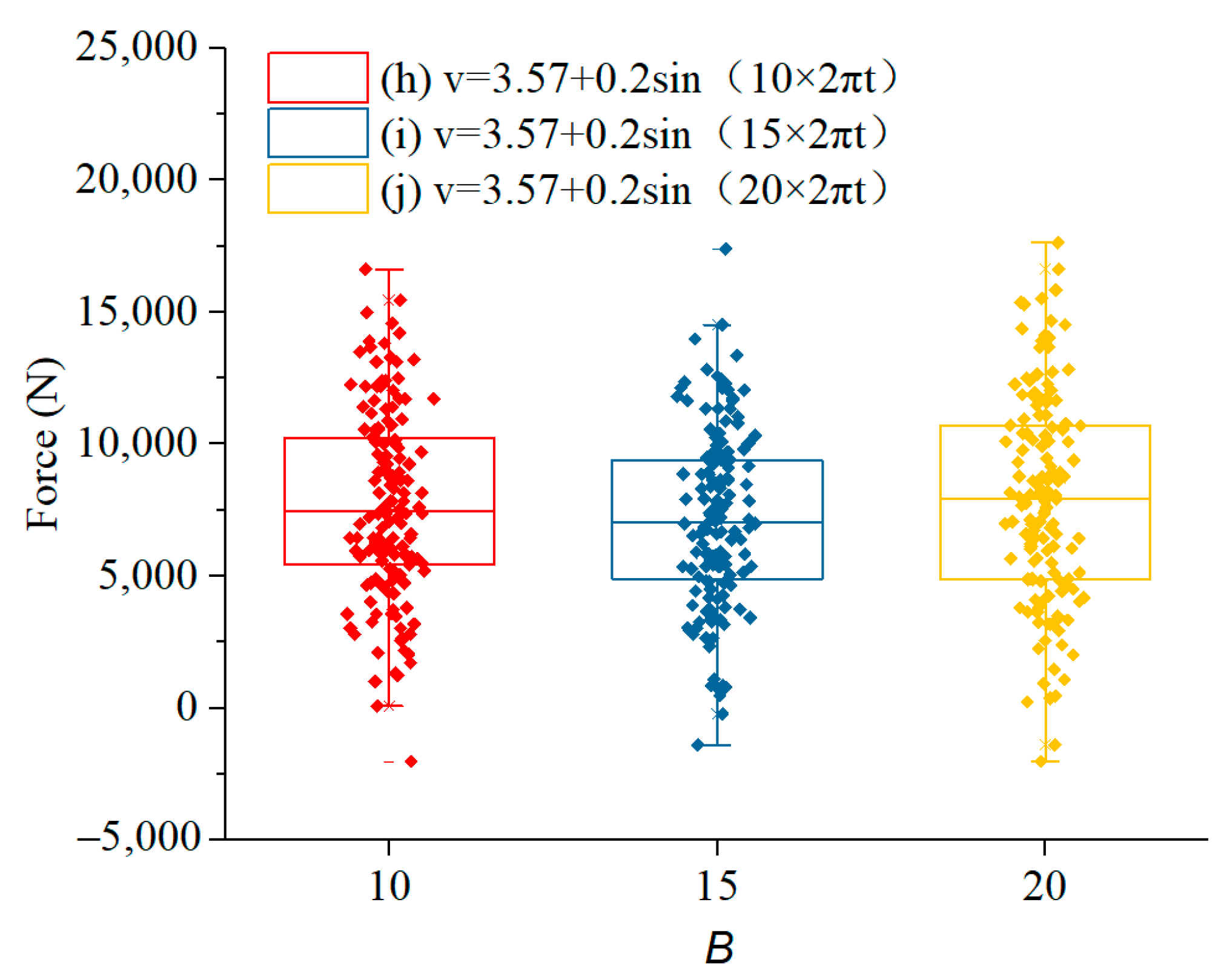
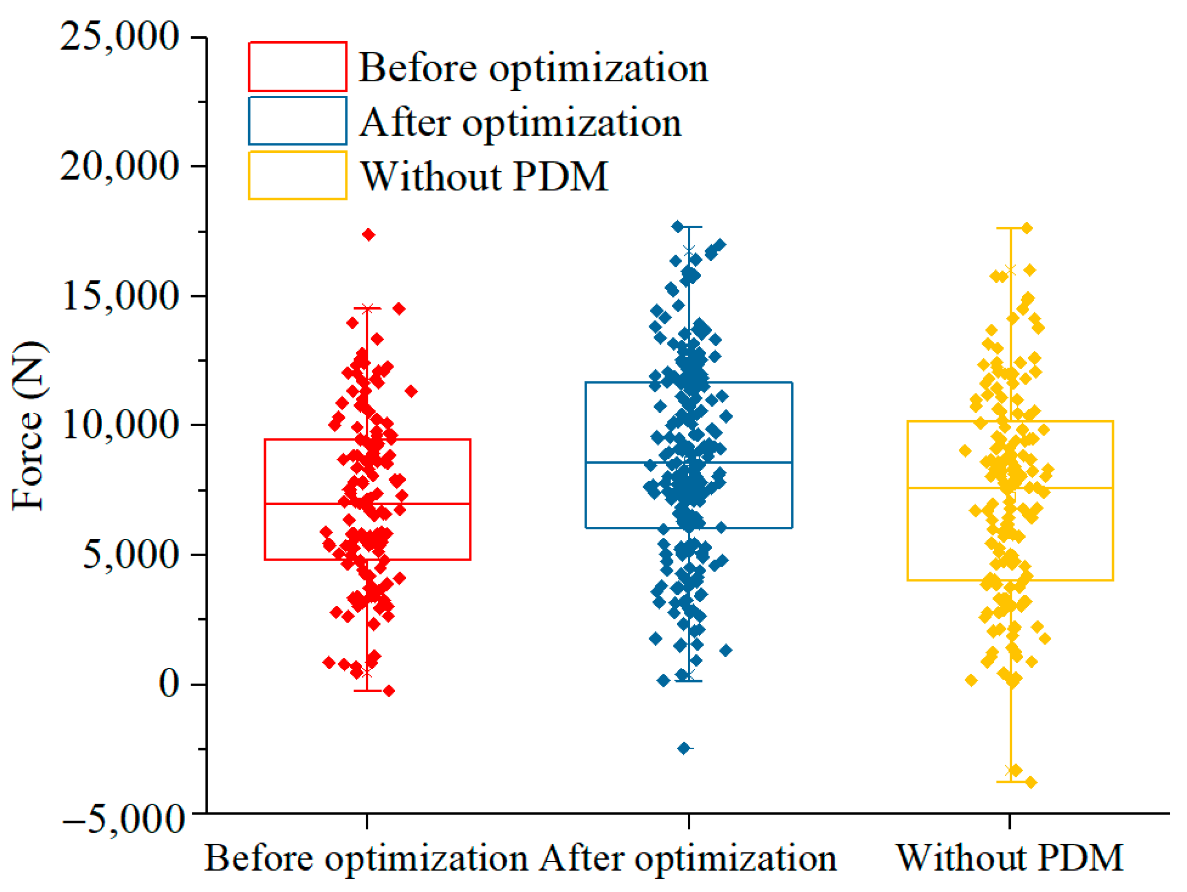
The fluid pulsation of the PDM has a negative effect on the performance parameters of the hydraulic impactor. As the fluctuation frequency of the inlet fluid increases, the impact values become more scattered, and the median and upper quartile values increase. On the other hand, as the fluctuation amplitude of the inlet fluid increases, there is a tendency for the dispersion of the impact values to decrease, and the median and upper quartile values show a downward trend. The negative effect of inlet fluid fluctuation can be eliminated by optimizing the hydraulic structure of the impactor. The median and upper quartile values of the impact force increase by 28.6% and 24.4%, respectively.
(2)
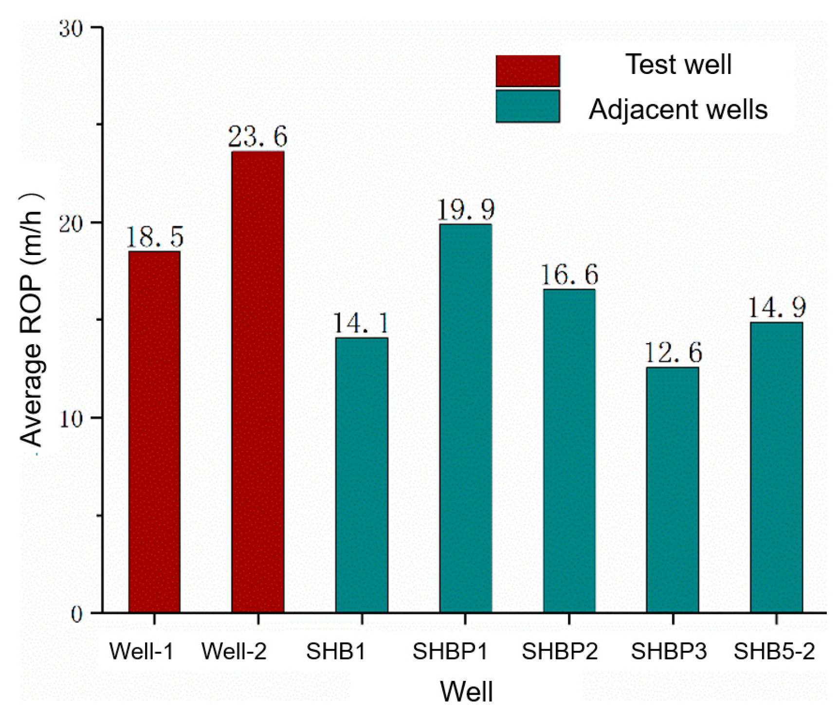
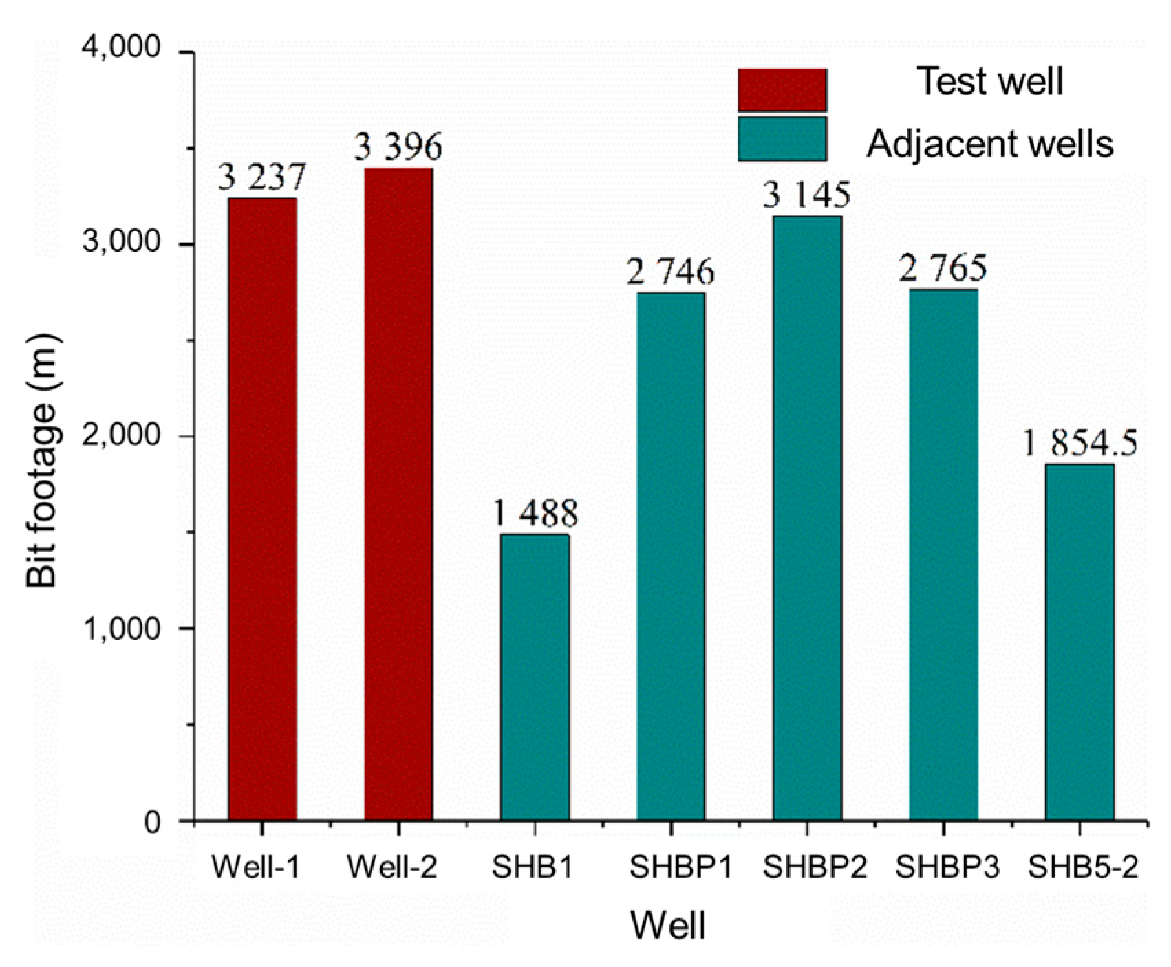
Two field tests are carried out in 2 wells in the shallow formation. The results indicate that the fluid fluctuation generated in the PDM can restrain the performance of the impactor and that the impact force can be increased by 24.4% to 28.6% through optimization design. The field tests also show that this technique can further improve the drilling efficiency and rotating stability of the polycrystalline diamond compact (PDC) bit, and the rate of penetration (ROP) and bit footage increase by 32.5% and 34.6%, respectively.
(3)
In future research, we suggest focusing research on the optimization of bit and drilling parameters with the aim of popularizing and applying this novel technique.
(4)
This technique has the potential for application in directional wells. In conventional PDM directional drilling processes, issues like drag and unstable toolface are often encountered. By placing the impactor below the PDM, it can improve drilling speed and drilling stability, thus offering the prospect of reducing drag and stabilizing the toolface.

Author Contributions

Methodology, W.L. (Wei Li); Formal analysis, H.X., Y.W. and W.C.; Investigation, Y.W. and W.C.; Resources, H.C.; Writing—original draft, W.L. (Wei Li); Writing—review & editing, H.C. and W.L. (Wenting Liu). All authors have read and agreed to the published version of the manuscript.

Funding

Science and Technology Research Project of Sinopec in China (Number P21080) and Postdoctoral Application Research Project of Qingdao in China.

Data Availability Statement

No more data can be shared due to privacy or ethical restrictions.

Acknowledgments

The project is supported by Science and Technology Research Project of Sinopec in China (Number P21080) and Postdoctoral Application Research Project of Qingdao in China.

Conflicts of Interest

The authors declare no conflict of interest.

References

  1. Zou, C.; Yang, Z.; Dong, D.; Zhao, Q.; Chen, Z.; Feng, Y.; Li, J.; Wang, X. Formation, distribution and prospect of unconventional hydrocarbons in source rock strata in China. Earth Sci. 2022, 47, 1517–1533. [Google Scholar]
  2. Boulesteix, K.; Poyatos-More, M.; Flint, S.; Taylor, K.; Hodgson, D. Transport and deposition of mud in deep-water environments: Processes and stratigraphic implications. Sedimentology 2019, 66, 2894–2925. [Google Scholar] [CrossRef]
  3. Li, G.; Zhu, R. Progress, challenges and key issues of unconventional oil and gas development of CNPC. China Pet. Explor. 2020, 25, 1–13. [Google Scholar]
  4. Li, G.; Tian, S.; Zhang, Y. Research progress on key technologies of natural gas hydrate exploitation by cavitation jet drilling of radial wells. Pet. Sci. Bull. 2020, 5, 349–365. [Google Scholar]
  5. Su, Y.; Lu, B.; Liu, Y.; Zhou, Y.; Liu, X.; Liu, W.; Zang, Y. Status and research suggestions on the drilling and completion technologies for onshore deep and ultra deep wells in China. Oil Drill. Prod. Technol. 2020, 42, 527–542. [Google Scholar]
  6. Jia, C.; Pang, X. Research processes and main development directions of deep hydrocarbon geological theories. Acta Pet. Sin. 2015, 36, 1457–1469. [Google Scholar]
  7. Chen, X.; Gao, D.; Guo, G.; Feng, Y. Real-time optimization of drilling parameters based on mechanical specific energy for rotating drilling with positive displacement motor in the hard formation. J. Nat. Gas Sci. Eng. 2016, 35, 686–694. [Google Scholar] [CrossRef]
  8. Detournay, E.; Defourny, P. A phenomenological model for the drilling action of drag bits. Int. J. Rock Mech. Min. Sci. Geomech. Abstr. 1992, 29, 13–23. [Google Scholar] [CrossRef]
  9. Jaime, M.; Zhou, Y.; Lin, J.; Gamwo, I. Finite element modeling of rock cutting and its fragmentation process. Int. J. Rock Mech. Min. Sci. 2015, 80, 137–146. [Google Scholar] [CrossRef] [Green Version]
  10. Liu, S.; Ni, H.; Wang, X.; Wang, P.; Li, N. Numerical study of the compound vertical and horizontal impact cutting with a single PDC cutter. Energy Rep. 2020, 6, 1520–1527. [Google Scholar] [CrossRef]
  11. Liu, S.; Ni, H.; Zhang, H.; Wang, Y.; Li, N.; Lyu, J.; Xie, H. Numerical study on optimal impact angle of a single PDC cutter in impact rock cutting. Energy Rep. 2021, 7, 4172–4183. [Google Scholar] [CrossRef]
  12. Liu, S.; Ni, H.; Jin, Y.; Zhang, H.; Wang, Y.; Huang, B.; Hou, W. Experimental study on drilling efficiency with compound axial and torsional impact load. J. Pet. Sci. Eng. 2022, 219, 111060. [Google Scholar] [CrossRef]
  13. Deen, C.; Wedel, R.; Nayan, A.; Mathison, S.; Hightower, G. Application of a Torsional Impact Hammer to Improve Drilling Efficiency. In Proceedings of the SPE Annual Technical Conference and Exhibition, Denver, CO, USA, 30 October–2 November 2011. [Google Scholar]
  14. Xu, Z.; Jin, Y.; Hou, B.; Don, J.; Pang, H.; Lu, Y. Rock Breaking Model Under Dynamic Load with the Application of Torsional and Axial Percussion Hammer. In Proceedings of the International Petroleum Technology Conference, Bangkok, Thailand, 14–16 November 2016. [Google Scholar]
  15. Staysko, R.; Francis, B.; Cote, B. Fluid Hammer Drives Down Well Costs. In Proceedings of the SPE/IADC Drilling Conference and Exhibition, Amsterdam, The Netherlands, 1–3 March 2011. [Google Scholar]
  16. Fowell, R.J.; Tecen, O. Studies in Water Jet Assisted Drag Tool Rock Excavation. Int. J. Rock Mech. Min. Sci. Geomech. Abstr. 1984, 21, A199. [Google Scholar]
  17. Tutluoglu, L.; Hood, M.; Barton, C. Investigation of the Mechanisms of Water Jet Assistance on The Rock Cutting Process. Int. J. Rock Mech. Min. Sci. Geomech. Abstr. 1984, 21, 75. [Google Scholar]
  18. Luiz, F.P.F. A bit-rock interaction model for rotary percussive drilling. Int. J. Rock Mech. Min. Sci. 2011, 48, 827–835. [Google Scholar]
  19. Zhou, X.; Zhang, J.; Zhang, D. Application of TorkBuster in Yuanba Area. Drill. Prod. Technol. 2012, 35, 15–17. [Google Scholar]
  20. Peng, M.; Li, S.; Wu, S.; Zhang, Y.; Wang, M.; Wang, K.; Fang, H. Application of Torsional Impact Hammer in Tahe Oil Field. Fault-Block Oil Gas Field 2012, 19, 622–625. [Google Scholar]
  21. Cheng, R.; Ge, Y.; Wang, H.; Ni, H.; Zhang, H.; Sun, Q. Self-Oscillation Pulsed Percussive Rotary Tool Enhances Drilling Through Hard Igneous Formations. In Proceedings of the IADC/SPE Asia Pacific Drilling Technology Conference and Exhibition, Tianjin, China, 9–11 July 2012. [Google Scholar]
  22. Li, W.; Wu, B.; Huang, G.; Yu, F.; Ni, H. Study on the main controlling factors and formation mechanism of motion states of bottom hole assembly in slightly-deviated wells. J. Energy Resour. Technol. 2022, 144, 123001. [Google Scholar] [CrossRef]
  23. Li, W.; Huang, G.; Ni, H.; Yu, F.; Huang, B.; Jiang, W. Experimental study and mechanism analysis of the motion states of bottom hole assembly during rotary drilling. J. Pet. Sci. Eng. 2020, 195, 107859. [Google Scholar] [CrossRef]
Figure 1. BHA of combined use of PDM and hydraulic impactor.
Processes 11 02392 g001
Figure 2. Three-dimensional structure of the impactor flow domain.
Processes 11 02392 g002
Figure 3. Analysis model of the hydraulic impactor.
Processes 11 02392 g003
Figure 4. Distribution of the impact generator without fluid pulsation.
Processes 11 02392 g004
Figure 5. Pressure fluctuation without PDM.
Processes 11 02392 g005
Figure 6. Pressure fluctuation with different flow velocities.
Processes 11 02392 g006
Figure 7. Box plot of impact amplitude at different frequencies when the input amplitude is 0.1 m/s.
Processes 11 02392 g007
Figure 8. Box plot of impact amplitude at different frequencies when the input amplitude is 0.15 m/s.
Processes 11 02392 g008
Figure 9. Box plot of impact amplitude at different frequencies when the input amplitude is 0.2 m/s.
Processes 11 02392 g009
Figure 10. Comparison of pressure fluctuation before and after optimization.
Processes 11 02392 g010
Figure 11. Comparison of pressure fluctuation with different drilling methods.
Processes 11 02392 g011
Figure 12. Comparison of average ROP.
Processes 11 02392 g012
Figure 13. Comparison of average bit footage.
Processes 11 02392 g013
Table 1. Operation parameter of PDMs.
PDM TypeRecommended Flow Rate (L/s)Rotational Speed (rpm)Maximum Torque (N·m)Output Torque (N·m)
LZ197x7.0L-6-8407.75–15.50139–27718141366
4LZ197x7.0L-84017.00–34.0085–17010,3677340
5LZ197x7.0L-4-84018.55–37.0879–15867005022
5LZ197x7.0L-5-84018.55–37.0879–15888666277
5LZ197x7.0L-6-84018.55–37.0879–15810,6407533
9LZ197x7.0L-4-84021.12–42.2372–14583156260
7LZ197x7.0L-5-84020.50–41.0075–15010,1977220
C9LZ197x7.0L-4-105025.17–50.4767–13512,7439022
Table 2. Frequency fluctuation of outlet of PDM.
PDM TypeFluctuation
Frequency/Hz
PDM TypeFluctuation
Frequency/Hz
LZ197x7.0L-6-8404.6~9.25LZ197x7.0L-6-8407.9~15.8
4LZ197x7.0L-8407.1~14.29LZ197x7.0L-4-84012~24.2
5LZ197x7.0L-4-8407.9~15.87LZ197x7.0L-5-84010~20
5LZ197x7.0L-5-8407.9~15.8C9LZ197x7.0L-4-105011.2~22.5
Table 3. The results of impact force at different velocity conditions.
Flow FactorMean Value/(N)Amplitude/(N)
A/(m/s)B/(Hz)
0071815564
0.11074604664
0.11584675132
0.12085425386
0.151076915033
0.151574875144
0.152088114974
0.21079685470
0.21571544638
0.22077825079
Table 4. Orthogonal table of cavity structure.
No.D4/(mm)L1/(mm)L2/(mm)
1629131
2629535
3629939
4669539
5669931
6669135
7709935
8709131
9709539
Compare values669535
Table 5. Comparison of valve structure parameters before and after optimization.
/D1/(mm)D2/(mm)D3/(mm)L1/(mm)D4/(mm)L2/(mm)D5/(mm)Median Force/(N)Upper Quartile Force/(N)
Before3224969566354370299471
After32249695703943903811,785
Table 6. Rock mechanical parameters of the test block.
Well Section/mDensity/(g·cm−3)Shear Modulus/GPaμUniaxial Compressive Strength/MPa
3000~48002.1981.00.2340.02
Table 7. Drilling parameters of test wells.
WellBit TypeWell Section/mDensity/(g·cm−3)WOB/kNRPM/(r·min−1)Flow Rate/(L·s−1)Bit Footage/mDrilling Time/hROP/(m·h−1)
Well-1SF56H31104~43411.2710050 + PDM47323717518.5
Well-2SI516MHBPX1221~46171.258060 + PDM553396143.723.63
Disclaimer/Publisher’s Note: The statements, opinions and data contained in all publications are solely those of the individual author(s) and contributor(s) and not of MDPI and/or the editor(s). MDPI and/or the editor(s) disclaim responsibility for any injury to people or property resulting from any ideas, methods, instructions or products referred to in the content.

