Abstract
Tangential effusion cooling of a combustor liner has a large difference from traditional effusion cooling on a plate. In this paper, numerical simulation is carried out to study the flow field, heat transfer characteristics and the factors affecting the cooling effectiveness of tangential effusion cooling of a combustor liner. It is found that the cooling film formed by the tangential jet is distributed in a divergent “horsetail” shape and adheres tightly to the inner wall of the liner, which increases the cooling area and effectiveness. Three different tangential inlet cooling hole arrangements and their cooling efficiencies are studied, and several important parameters that affect the cooling effectiveness are summarized. Then, an improved cooling hole arrangement is proposed, and its cooling efficiency is studied and compared with those of the original three arrangements. The results show that the new arrangement significantly improves the comprehensive cooling efficiency and decreases the wall temperature, thus confirming the effectiveness of the improved strategy and providing a theoretical basis for the subsequent cooling design to improve the cooling efficiency for a combustor liner.
1. Introduction
The combustor is one of the three core components of a gas turbine engine. With the development of technology, the exit temperature of the combustor of an aeroengine has reached approximately 2000 K and increased continuously [1]. The combustor liner is the component in which the fuel is directly burned, which has the characteristics of a high combustion temperature and poor cooling conditions. Combustor liners are generally machined from metal materials, and the most commonly used materials for combustor liners have a long-term operating temperature lower than 1250 K [2], while the local combustion temperature in combustor liners is up to 2500 K. As liners work for a long time at such high temperatures, efficient cooling must be used to reduce the liners’ actual wall temperatures.
Currently, the most widely used cooling method in combustors is film cooling, including wiggle strips, splash-cooling rings, stacked rings, machined rings, and film cooling with augmented convection or impingement. Conventional film cooling has the disadvantages of high cooling airflow consumption, jagged temperature distribution, large temperature gradient and stress concentration. Augmented film cooling improves the cooling effect, although it requires a double-walled structure, increasing the cost and weight. In addition, there is a large difference in temperature between the two walls, which easily leads to nonuniform expansion. Transpiration cooling is the cooling use of porous material as the cooling wall. The pores in the wall comprise a large number of tiny cooling passages and provide a very large cooling surface area for the wall. In addition, air jets from the pores immediately coalesce to form a cooling film over the inner wall because of the tiny and uniform enough pores distributed over the wall. For this reason, researchers have vigorously developed transpiration cooling, which is considered to offer the most potential and efficient cooling for liners [3]. However, its practical application is limited because the porous material cannot meet the oxidation resistance requirements and the pore channels are easily blocked. Then, “semi-transpiration” cooling methods such as “Transply” and “Lamilloy” cooling were developed based on this concept, although their application in large combustor liners is hampered by the high manufacturing costs, difficult process control, and low mechanical strength [4].
Another practical form of transpiration cooling, namely, effusion cooling, is gaining great attention due to its good cooling effect and simplicity of implementation. Effusion cooling, also known as full-coverage air film cooling, is a cooling scheme in which a large number of small holes (generally less than 1.0 mm in diameter) are densely arranged on the wall to be cooled. Effusion cooling consumes 1/3 to 2/3 less cooling airflow than conventional film cooling, and if the hole diameter is reduced and the number of holes is increased, then it is theoretically possible to achieve an isothermal wall surface capable of reducing the surface temperature gradient by 70% compared to “Lamilloy” cooling, which is conducive to reducing the thermal stress and improving the liner’s service life [5]. Compared to conventional film cooling, effusion cooling has smaller holes and a denser hole spacing distribution. Effusion cooling is considered to be a promising cooling technology for the hot components of advanced turbine engines [6,7].
Early studies of effusion cooling focused on the effects of the inclination angle of the cooling holes on a flat plate, the thickness of the plate, and the arrangement of multiple rows of holes on the cooling efficiency. Bergeles G. [8] and Afejuku W. O. [9] studied the influence of the hole arrangement on the cooling efficiency in a certain blowing ratio range and found that the cooling effect of a double-row intersectant arrangement of holes is better than that of single-row holes and that the cooling effect of intersectant rows is better than that of aligned rows. Kadotani K. [10] and Brown A. [11] studied the influence of the mainstream turbulence intensity on the cooling characteristics and found that when the mainstream turbulence intensity is greater than 0.082, it will have a greater effect on the mixing process of the jet and the mainstream, thus affecting the distribution of the cooling efficiency. Jin Wang [12] studied the cooling efficiency for a combustor liner and the distribution of the temperature at the exit of the combustor when the inclination angle of the effusion cooling holes was 30°, 60° and 90° with numerical simulation. They found that effusion cooling can reduce the wall temperature maximum by 31.7%, and when the hole inclination angle is 30°, the cooling effectiveness is highest and the temperature distribution at the exit of the combustor is most uniform. H. Wei [13] studied the cooling effect of effusion cooling with fan-shape holes at different inclination and expansion angles and found that the inclination angle dominantly impacts the separation flow inside the hole and governs the vortex structure and the downstream film cooling effectiveness. Chao Zong [14] studied the flow field near the wall and the heat transfer characteristics of effusion cooling using the adiabatic model and the conjugate heat exchange model, and they verified the results with experimental data. It was found that the adiabatic model has difficulty in predicting the wall cooling effectiveness distribution on the inner surface of the wall and overestimates the discharge coefficient by 16.5%, although its simulation accuracy for the near-wall flow field structure is not lower than that of the conjugate heat exchange model and the film thicknesses calculated by the two models are basically the same.
In recent years, compound angles have become the focus of effusion cooling research. Goldstein [15], Chen [16] and Natsui [17] explored the influence of the compound angle on effusion cooling at different blowing ratios and found that the compound angle could effectively increase the spread of the cooling air film, correspondingly improving the cooling efficiency at high blowing ratios. Ekkad [18] and Lee [19] studied the cooling efficiencies of different coolants with different densities at large compound angles and found that coolants with lower densities have higher cooling efficiencies. Brice Michel [20] experimentally found that the cooling efficiency can greatly be enhanced by a swirling injection. They compared different injection models with the experimental results and found that the standard model has significant difficulty in predicting high-accuracy results, while the multi-perforation model has high accuracy. Walters D. K. [21,22,23,24] studied the flow mechanism of effusion holes under different compound angles and found that under conventional injection holes without compound angles, a symmetrical counterrotating vortex pair occurs in the cross-flow region. The counterrotating vortex pair sucks the high-temperature mainstream up into the cooling jet, strengthening the mixing between the mainstream and the coolant and deteriorating the cooling effect. With the appearance of and increase in the compound angle (45°, 60° and 90°), the counterrotating vortex pair gradually becomes asymmetric. At a 90° compound angle, the counterrotating vortex pair disappears, becoming a single large vortex system structure.
The abovementioned studies of effusion cooling with compound angles basically focused on flat plate cooling, although there are large differences for a combustor liner: since a combustor liner is generally cylindrical with a large curvature, when the effusion holes have a certain compound angle, the cooling airflow will adhere to the inner wall and rotationally move forward after entering the combustor liner. The rotational motion can greatly enhance the adhesion of the coolant to the inner wall and reduce the mixing with the mainstream. Based on this effect, Chin J. [25,26,27] proposed tangential effusion cooling for combustor liners, which can realize a spiral motion of the cooling film against the wall and greatly enhance the cooling efficiency. Wang Tao [28] conducted a simulation study of the wall temperature of a liner with tangential effusion cooling and found that the maximum temperature rise at the liner wall is only 185 K and that the highest cooling efficiency approaches 90%. Yang Guang [29] compared the cooling efficiency for a combustor liner using conventional inclination angle effusion holes and tangential inlet effusion holes, and they found that tangential inlet effusion has a higher cooling efficiency. The highest local cooling efficiency is 0.98 at a blowing ratio of 10.4, and the average cooling efficiency for the combustor liner is 0.93. The tangential effusion structure also has better film spreading and flow uniformity.
Since the published papers on large curvature surfaces with tangential effusion cooling are very limited and their flow characteristics and cooling mechanisms have not been clearly clarified, it is necessary to further study the flow and heat transfer characteristics of tangential effusion cooling films in combustor liners to reveal the mechanism of the high efficiency of tangential effusion cooling and find methods to further improve the cooling efficiency.
2. Physical Model and Boundary Conditions
2.1. Geometry Description
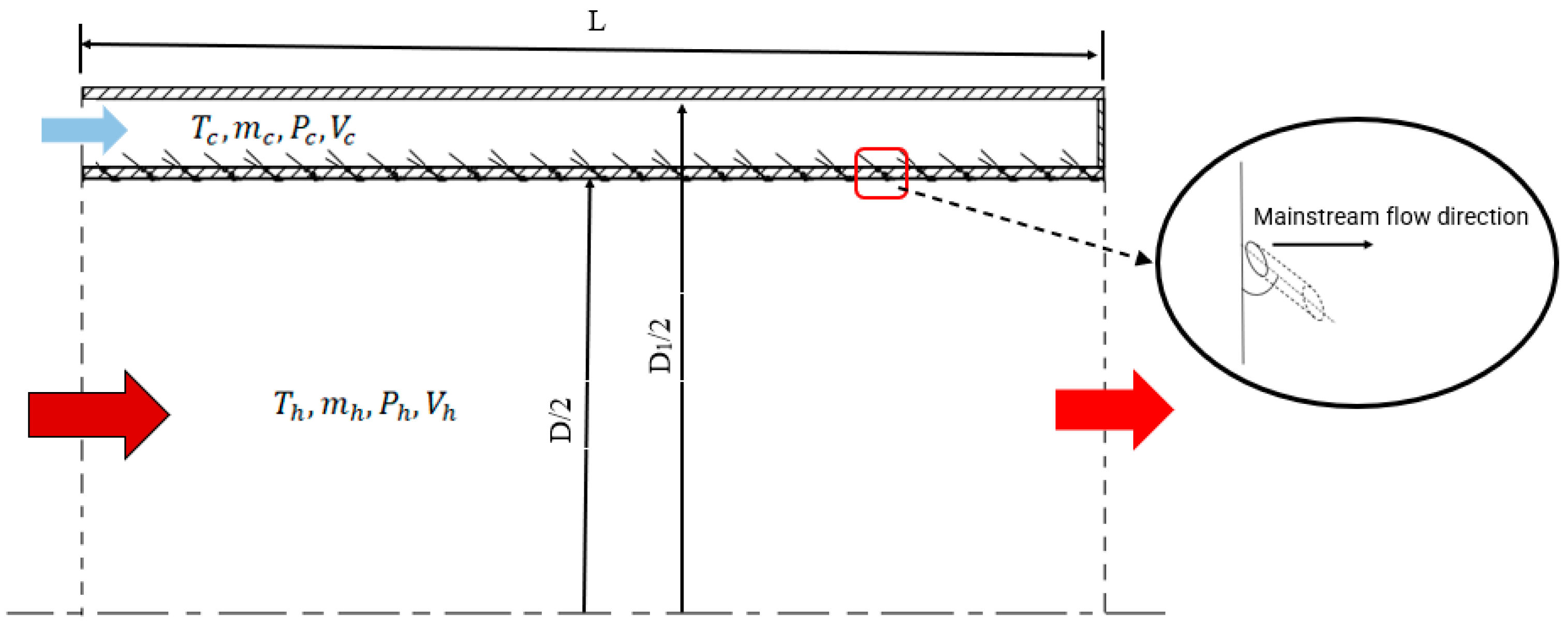
The physical model of combustor liner cooling in this paper is shown in Figure 1, where D is the inner diameter of the liner, D1 is the inner diameter of the combustor case, and L is the length of the combustor liner.
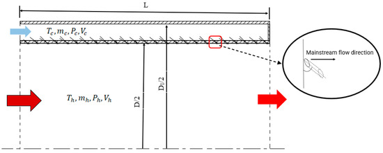
Figure 1.
Schematic of the physical model.
Compared with flat plate effusion cooling with a compound angle, tangential effusion cooling of the combustor liner has a more complicated structure and a tangential angle , which does not exist in plate effusion cooling. The structure of the combustor liner with tangential effusion cooling holes in this paper is shown in Figure 2, where d is the diameter of the cooling holes, is the inclination angle, is the compound angle, and is the tangential angle. Within the present study, D = 152 mm, D1 = 180 mm, L = 100 mm, , , , and d = 0.8 mm.
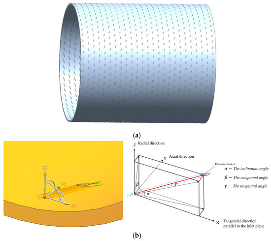
Figure 2.
Combustor liner with tangential effusion cooling holes. (a) 3D model of the combustor liner. (b) Structure and definition of the tangential effusion cooling hole.
2.2. Boundary Conditions
The inlets of both the mainstream and the secondary stream (cooling air) are “mass flow inlets”, the outlet is a “pressure outlet”, and the composition of both the mainstream and the secondary stream is air. Considering the cooling by the bypass air in a real gas turbine engine, the temperature of the combustor case is assumed to be constant; therefore, the wall of the secondary flow is set as a no-slip wall with a temperature of 800 K, and the wall of the liner is set as a coupled wall. The boundary conditions are shown in Table 1, which are based on an advanced combustor.

Table 1.
Parameters for the simulation.
The liner wall material is GH5188 (Haynes 188), which is commonly applied in the aviation industry. The physical and heat transfer characteristics of GH5188 are as follows:
In the numerical calculation process, the wall temperature is first estimated from the mainstream temperature and secondary flow temperature; the thermal conductivity, specific heat capacity and other parameters under the corresponding temperature are then found in Table 2; calculations are then performed; and the results are compared with the initial given wall temperature. If the difference is greater than 3%, then the material parameters are renewed according to the calculated temperature, and the calculation is then performed again until the difference between the two adjacent calculation results is less than 3%. At this time, the difference in the physical characteristic parameters can be ignored, and the parameters are considered to be in line with the facts.
Table 2.
Physical and heat transfer characteristics of GH5188.
3. Mathematical and Numerical Modeling
In this study, the commercial computational fluid dynamics software ANSYS FLUENT 2021R2 is used to perform the 3D numerical simulations. The flow in this study can be considered a three-dimensional, steady-state, gravity-negligible, compressible, ideal gas flow. The control equations for the numerical simulation are represented by Equations (1)–(3).
Continuity equation:
Momentum equation:
and energy equation:
The detailed descriptions of the control equations have been shown in references [30,31].
3.1. Turbulence Model
For a high-efficiency numerical calculation, the Reynolds average method is usually used to solve the time-averaged N–S equation (RANS). To make the N–S equation closed, different assumptions are proposed; thus, different turbulence models have been developed, such as the k-ε model and k-ω model, where the k-ε model also includes the k-ε standard model, k-ε realizable model and k-ε RNG model.
Li [32] compared the numerical results of different turbulence models with the existing experimental data for a transverse jet in a crossflow, which is similar to the situation of the cooling jets from the effusion holes in the hot mainstream, and found that different turbulence models have different prediction accuracies, as shown in Table 3.
Table 3.
Prediction accuracy under different turbulence models for a transverse jet in a crossflow [32].
H. Kwon [33] summarized the accuracies of different turbulence models in several references with regard to the prediction of film cooling, and found that the average difference from the experimental data under the k-ω SST model is the least—around 7.2%. Thus, the k-ω SST model is used in this paper because of its better prediction ability for film cooling.
For the k-ω SST model, a mixing function is introduced into the boundary layer, and a damping cross-diffusion term is introduced into the ω equation. The turbulent viscosity is also modified to explain the turbulent shear force so that it has higher accuracy and a wider application environment [30]. The transport equation is shown as follows:
3.2. Radiation Modeling
Thermal radiation is a very important heat transfer resource for the increase in the wall temperature. The discrete ordinate (DO) model is a radiation model with relatively high computational accuracy and low resource occupation. The radiative transfer equation is presented in Equation (6), and its boundary conditions are given by Equation (7), as shown in reference [11]
where a is the absorption coefficient, I is the radiation intensity, is the position vector of the traveling radiative ray, is the direction vector of the traveling radiative ray, is the direction vector of the traveling radiative ray incident on the control volume, is the Stefan–Boltzmann constant, is the scattering coefficient, T is the local temperature, Ψ is the scattering phase function, is the solid angle, is the black body radiation intensity, is the wall area normal vector, and is the position vector on the wall.
The absorption coefficient of the mixture a can be calculated using the weighted sum of the gray gases model [34]. The absorptivity of the mixture is the weighted sum of the H2O vapor absorptivity and CO2 absorptivity.
To accurately obtain the wall temperature, the discrete ordinate model is used in this paper.
3.3. Mesh and Independence Study
To reduce the calculation amount, a 90° sector is used for meshing and simulation. The model is meshed via fluent meshing. Since the size of the cooling holes is much smaller than the combustor size, a refined grid is used around the cooling holes and liner wall, while a relatively coarse grid is implemented in other regions, as shown in Figure 3. The minimum orthogonal mesh quality is 0.12, which meets the quality requirements of the simulation. Because the k-ω SST model requires the y+ of the first-layer near-wall grid to be less than 2.0 [35], in this study, this first-layer near-wall grid distance is kept y+ ≈ 1.

Figure 3.
Model grid.
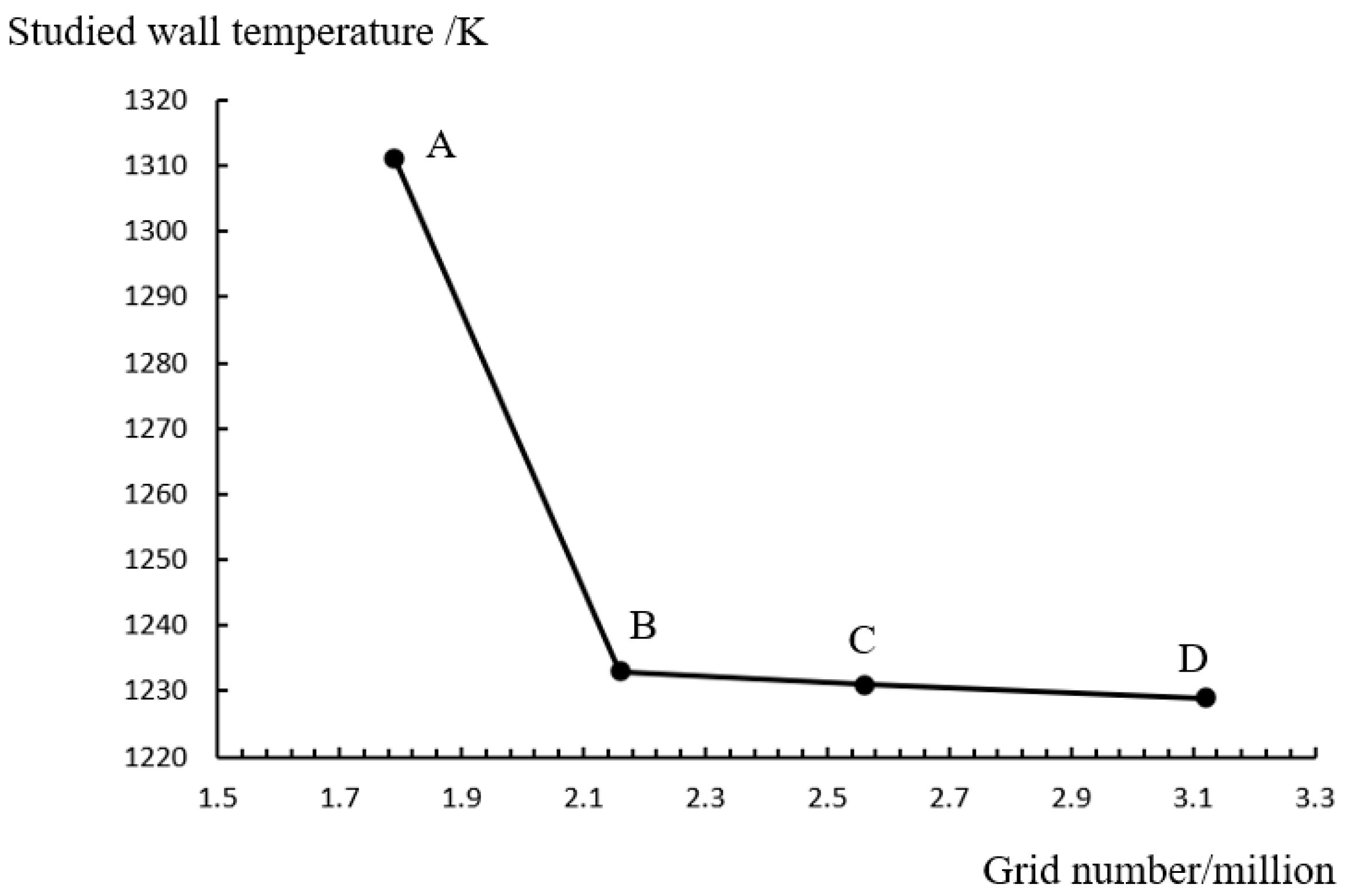
To validate the effect of the mesh size on the computed flow parameters, a grid independence study is conducted, as shown in Figure 4. Four meshes (Grid A—1.79 million, Grid B—2.16 million, Grid C—2.56 million, and Grid D—3.12 million) are used to carry out the simulations with identical boundary conditions. Considering the exist of very steep temperature gradient between the 2nd and 3rd rows of the cooling holes, the local temperature at the central point between the 2nd and 3rd rows is chosen for the mesh independence study. For the temperature at this point, only a 0.16% variation is found when the mesh varies from Grid B to Grid C, which is much smaller than the 6.3% variation when the mesh varies from Grid A to Grid B. To balance the calculation accuracy and computational cost, Grid B is used to perform the numerical simulations.

Figure 4.
Grid independence study.
4. Results and Analysis
4.1. Flow and Heat Transfer Characteristics of the Film
To study the flow of a cooling air jet after it enters the liner, a single hole in the wall is taken as the object of study and the pathlines from the hole are obtained, as shown in Figure 5a. For comparison, the pathlines of the flow in traditional effusion cooling of a plate obtained by Kwon [33] and Ji [36] are shown in Figure 5b,c. For the tangential effusion cooling of the combustor liner, the cooling air flows spirally against the wall and tightly adheres to the inner surface after entering the liner; thus, a cooling film tightly adhered to the wall surface can soon be formed. In addition, under the interaction with the mainstream, the cooling air flow is distributed in a divergent “horsetail” shape on the inner wall of the liner. This means that the cooling film from the hole becomes increasingly wider along the pathlines; subsequently, an increasingly larger area is cooled by the film from the hole. However, for the traditional effusion cooling of a flat plate, most of the cooling air pathlines fail to adhere to the wall surface and quickly integrate into the mainstream due to the effect of the inclination angle. This is the reason why tangential effusion cooling has a greater cooling effectiveness than the conventional inclination angle effusion cooling in reference [29].
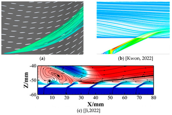
Figure 5.
Pathlines from effusion holes. (a) Pathlines from the tangential effusion cooling hole in the present study. (b) Pathlines from the conventional effusion cooling hole in the paper by Kwon [33]. (c) Pathlines from the conventional effusion cooling holes in the paper by Ji [36].
To study the heat exchange of cooling air in the hole and after entering the liner, the temperature contours through the centerline of an effusion hole are obtained, as shown in Figure 6a. For comparison, the temperature contours of conventional effusion cooling in the study by Venkatesh Vishal [37] are shown in Figure 6b. It can be found that for conventional effusion cooling (Figure 6b), intensive heat exchange with the high-temperature mainstream occurs around the cooling air jet, while for tangential effusion cooling (Figure 6a), intense heat exchange occurs only around the upper edge/lip of the cooling hole exit. This can be explained by the fact that around the upper edge/lip of the cooling hole exit, the flow is disturbed by the lip of the hole and directly contacts the high-temperature mainstream; thus, the turbulence intensity and temperature gradient of the flow here are larger than those in other places, which leads to intensive heat and mass exchange. However, at the downstream lip of the cooling hole exit, the cooling air tightly adheres to the wall and the flow is nearly not turbulent; thus, the heat and mass exchange are very slow there. Therefore, for tangential effusion cooling, the key factor to enhance the cooling effectiveness is to find ways to reduce the heat exchange and mixing at the upper edge/lip of the cooling holes.
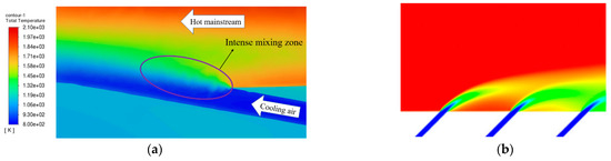
Figure 6.
Contour of the total temperature near the cooling hole. (a) Tangential effusion cooling in the present study. (b) Conventional effusion cooling in the study by Venkatesh Vishal [37].
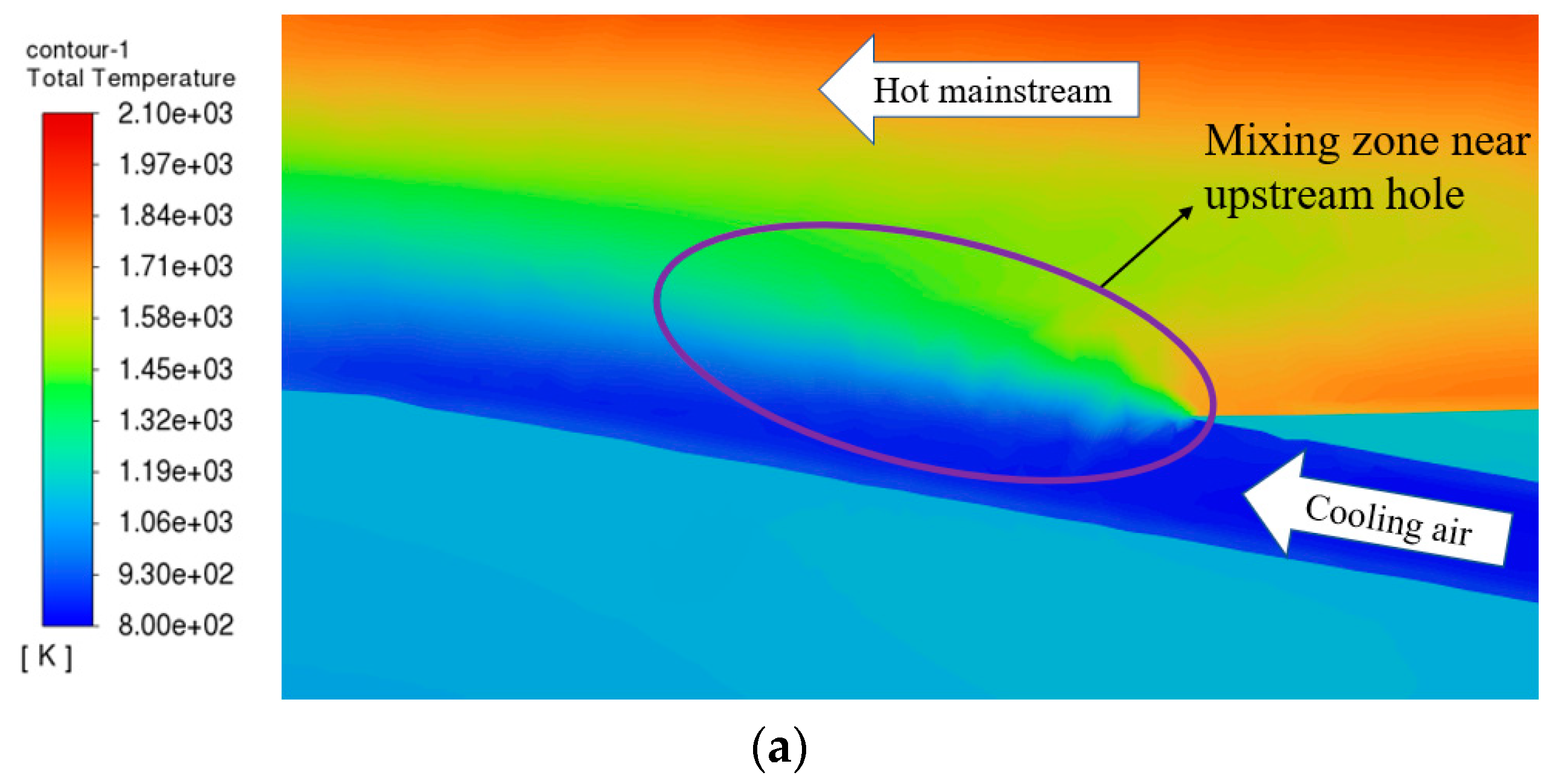
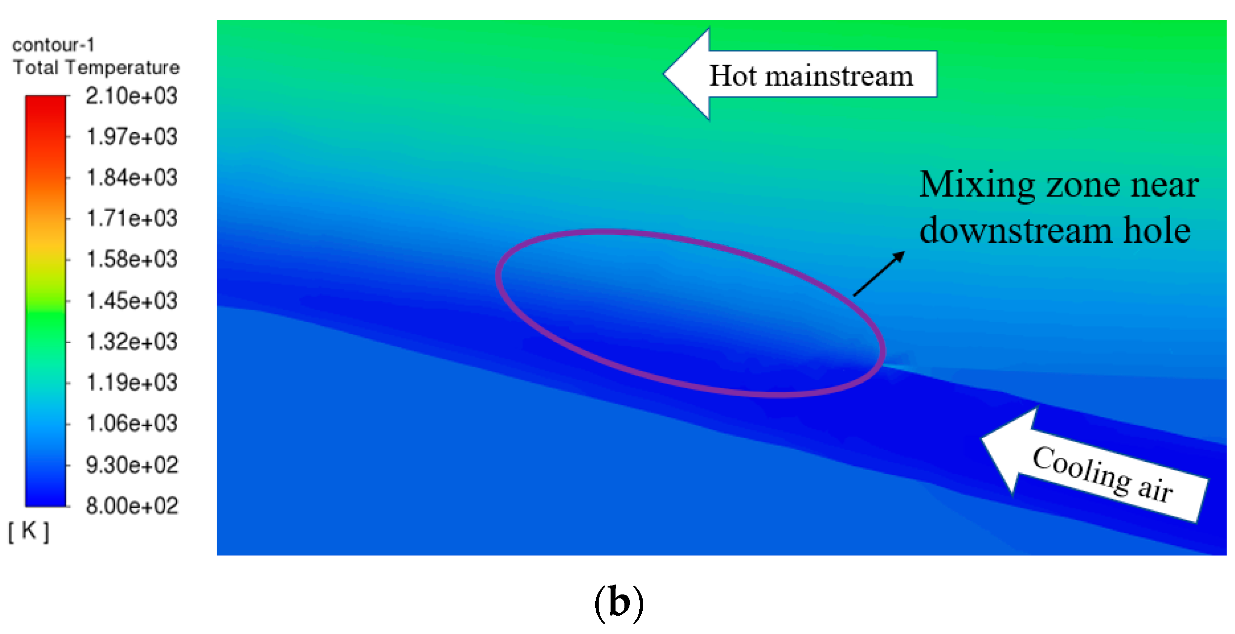
Furthermore, the contours of the temperature through the cooling holes at two different locations in the axial direction are obtained, as shown in Figure 7, where Figure 7a is the temperature contour around a hole in the 4th row and Figure 7b is the temperature contour around a hole in the 11th row. From the comparison of Figure 7a,b, it can be seen that the heat exchange at the lip of the downstream hole exit is significantly lower than that at the lip of the upstream hole exit, while the heat exchange at the exit of the 4th row hole is much more intensive than that at the exit of the 11th row hole.
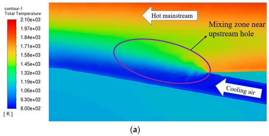
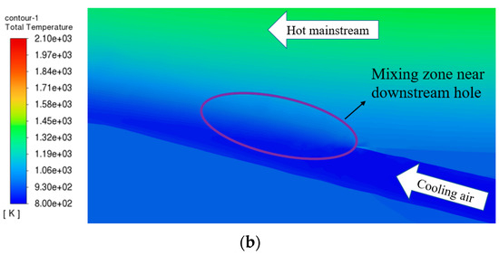
Figure 7.
Heat exchange at the upper lip of the cooling hole exit.
The turbulent kinetic energy around the cooling holes in the 4th and 11th rows is shown in Figure 8. It can be seen that there is a high turbulent kinetic energy region at the exit of the 4th row cooling hole, as shown in Figure 8a, and the value is obviously higher than that at the exit of the 11th row shown in Figure 8b. This can explain why the heat exchange at the exit of the 4th row hole is much more intensive than that of the 11th row: due to the spiral movement and tight adhesion to the wall of the upstream cooling film, the newly formed cooling film at the downstream cooling hole is in a “compressed” state, which greatly reduces the turbulence intensity and heat exchange at the upper lip of the hole exit. Therefore, compression of the cooling film by the upstream cooling airflow as much as possible contributes to reducing the mixing of the film with the high-temperature mainstream and increasing the cooling effectiveness.
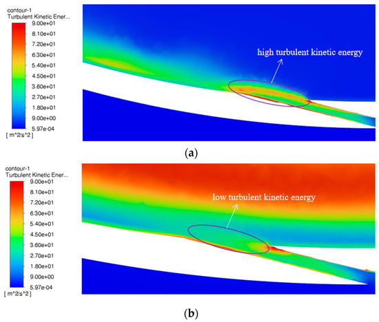
Figure 8.
The turbulent kinetic energy around the cooling hole exit: (a) hole at the 4th row; and (b) hole at the 11th row.
The temperature distributions along the radial direction of the combustor near the cooling hole exit in the 4th row and near the cooling hole exit in the 11th row are quantitatively obtained, as shown in Figure 9. It is obvious from Figure 9 that the temperature gradient near the cooling hole exit in the 4th row is very large—246 K/mm—while the temperature gradient near the cooling hole exit in the 11th row is relatively small—78 K/mm. The wall temperature near the 4th row hole is approximately 1121.6 K, and the wall temperature near the 11th row hole is approximately 970.2 K. It can be seen from Figure 9 that the cooling effectiveness near the 4th row cooling hole is better than that near the 11th row cooling hole, and the wall temperature is higher than the film temperature at the exit of the cooling hole, which means that the convective heat transfer direction between the wall and the film is from the wall surface to the cooling film, while the temperature rise in the wall is mainly caused by the heat radiation from the high-temperature mainstream.
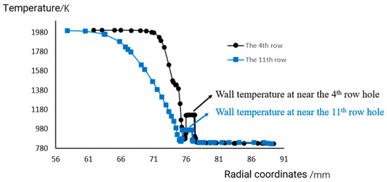
Figure 9.
Temperature distributions along the radial direction of the combustor near the cooling hole exits in the 4th and 11th rows.
4.2. Comparative Study of the Influence of Different Cooling Hole Arrangements on the Cooling Efficiency
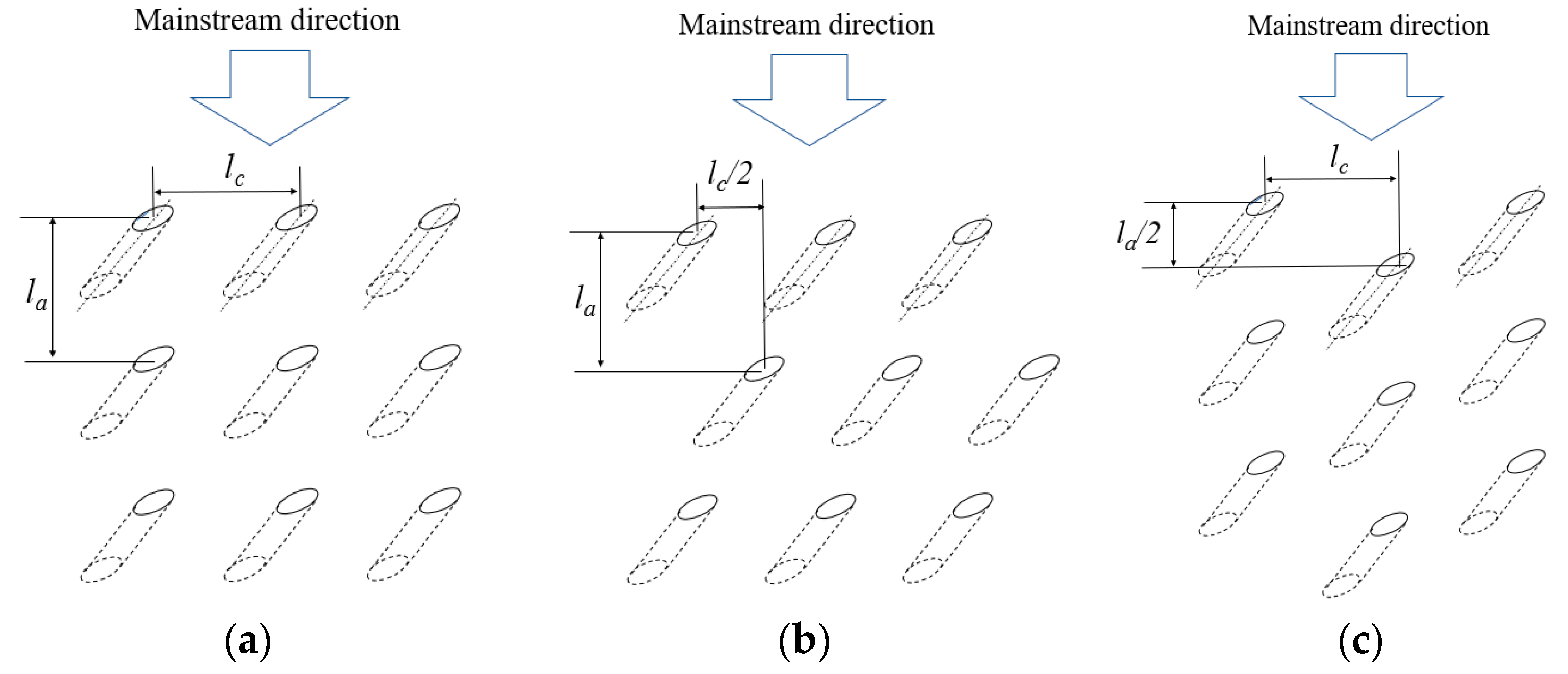
Based on the above study, to further compare the influence of different arrangements of tangential inlet cooling holes on the cooling efficiency and to study the interaction of films issued from different cooling holes and their influence on the cooling effectiveness, three different arrangements of cooling holes on the combustor liner are studied in this paper, as shown in Figure 10. Figure 10a shows an aligned arrangement row by row (hereinafter referred to as “arrangement a”), Figure 10b shows an arrangement staggered in a 1/2 row circumferentially (hereinafter referred to as “arrangement b”), and Figure 10c is an arrangement staggered in a 1/2 column axially (hereinafter referred to as “arrangement c”). In Figure 10, the vertical direction is axial, the left and right directions are circumferential, lc is the circumferential spacing of the holes, and la is the axial spacing of the holes.
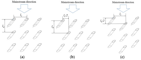
Figure 10.
Three different arrangements for the cooling hole layout.
The same boundary conditions (as in Table 1) are adopted, and the same quantity and quality of grids are obtained for the above three models. The cooling hole diameter d, inclination angle , compound angle , tangential angle , liner diameter D and other geometric parameters are all the same.
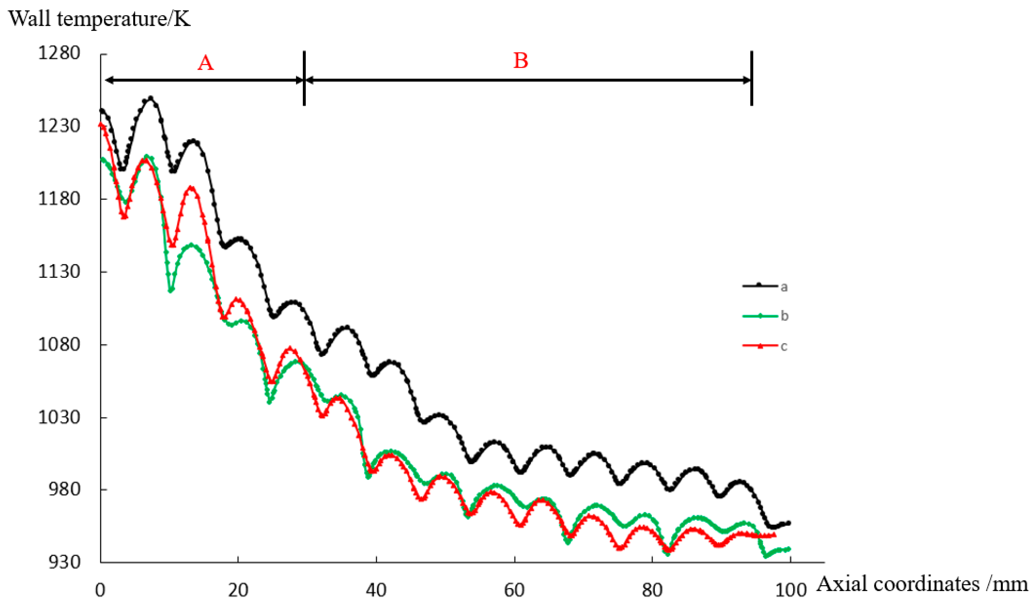
Figure 11 shows the temperature distribution on the inner wall along the axial direction of the liner under the three different cooling hole arrangements. From the figure, it can be seen that for all three arrangements, the temperature of the inner wall is very high at the entrance (approximately 1300 K), and it then rapidly decreases from approximately 1300 K to approximately 1050 K. By the second half of the liner, the wall temperature starts to slowly drop and then remains basically constant—at approximately 1000 K for a distance near the exit. The high wall temperature near the first row of cooling holes at the entrance is mainly caused by no cooling air in the gap between the two adjacent cooling holes; thus, this area suffers from direct flushing by the high-temperature mainstream. However, behind the second row of cooling holes, the wall temperature is still approximately 1260 K. The main reason, as analyzed in Section 4.1, is that the jets from the tangential inlet cooling holes at the entrance of the liner fail to be compressed by the other cooling jets and the cooling jets poorly adhere to the inner wall, which leads to intensive heat exchange between the cooling jets and the high-temperature mainstream, reducing the cooling effect; thus, the wall temperature is high.
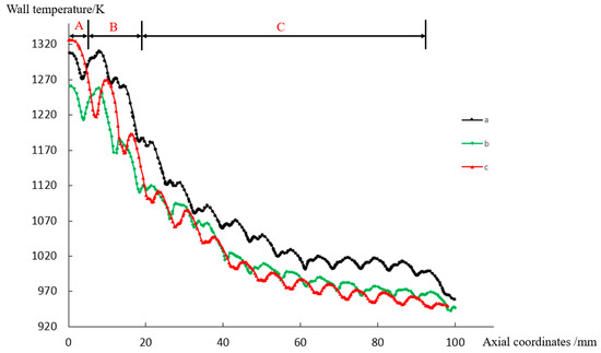
Figure 11.
Inner wall temperature along the axial direction under the three different cooling hole arrangements.
For the three types of cooling hole arrangements, the inner wall temperature of arrangement “c” is the highest while the inner wall temperature of arrangement “b” is the lowest at the liner inlet part (section “A” in Figure 11). After the first row hole position, in section “B” in Figure 11, the inner wall temperature of arrangement “c” rapidly decreases and becomes lower than the inner wall temperature of arrangement “a” but still higher than the inner wall temperature of arrangement “b”. With regard to section “C”, the inner wall temperature of arrangement “c” becomes lower than that of arrangement “b”, and arrangement “c” becomes the arrangement with the lowest wall temperature.
Figure 12 shows the distribution of the outer wall temperature along the axial direction for the three cooling hole arrangements. It can be seen from the figure that the trend of the temperature change is similar to that for the inner wall, i.e., the wall temperature rapidly decreases in the first half of the liner, while the wall temperature slightly decreases in the second half. However, a significant difference from the inner wall is that among the three different arrangements, the outer wall temperature of arrangement “a” is always higher than that of the other two arrangements, and the outer wall temperature of arrangement “c” is higher than that of arrangement “b” and lower than that of arrangement “a” in section “A” in Figure 12. In contrast, on the inner wall, the temperature in section “A” under arrangement “c” is slightly higher than that under arrangement “a”. The main reason for this difference is that arrangement “c” with a 1/2 staggered column axially leads to the halving of the number of cooling holes in the first row so that the gap area between the holes directly flushed by the high-temperature mainstream is doubled and thus the inner wall temperature is the highest. However, the outer wall is not directly flushed by the high-temperature mainstream and is cooled by the cooling air and cooling holes on the outer wall, as well as by the axial heat conduction within the wall, resulting in the outer wall temperature not being the highest for arrangement “c”.

Figure 12.
Outer wall temperature along the axial direction under the three different cooling hole arrangements.
The average temperatures of the inner and outer walls under the three cooling hole arrangements are obtained, as shown in Table 4. It can be quantified that the wall temperatures of arrangement “b” and arrangement “c” are comparable, although arrangement “c” has the lowest temperature and the best cooling effectiveness, while arrangement “a” has the highest wall temperature, i.e., the worst cooling effectiveness.
Table 4.
Wall temperatures under three different cooling hole arrangements.
4.3. Analysis and Summary
Figure 13 shows a schematic of the planar expansion of the three arrangements and the direction of the jet flows from the cooling holes, where lc = 7.96 mm and la = 7.2 mm.
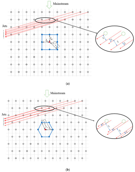
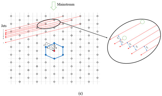
Figure 13.
Planar expansion of the three arrangements and the direction of the jet flows from the cooling holes.
- (1)
- Unit cooling area of the cooling hole
The parameter is defined as the unit cooling area of a hole in a certain arrangement, characterizing the area of a polygon enclosed by the nearest surrounding holes divided by the number of holes within the enclosed polygon, i.e.,, where A is the area enclosed between adjacent holes and n is the number of adjacent nearest holes. Assuming that the amount of cooling brought to the wall by each hole is Q, a smaller indicates that the same amount of cooling is distributed over a smaller area, and thus, that the cooling efficiency is higher. It can be calculated that for arrangement “a”, ; for arrangement “b”, ; and for arrangement “c”, . It can be concluded that the cooling efficiencies of arrangements “b” and “c” are higher than that of arrangement “a”, while the cooling efficiencies are comparable for arrangements “b” and “c” when only the effect of this factor is considered.
- (2)
- Interaction between the upstream and downstream jets
Since the tangential angle is 15 degrees, it can be seen from Figure 13 that the flow distributions of the cooling jets under different arrangements are very different. The distances between the upstream jet and the two adjacent downstream jets are defined as S1 and S2, respectively. S1 and S2 characterize the cooling of the upstream jet in the gap between the downstream cooling holes and the overall uniformity of the cooling jet distribution. The closer S1 is to S2, the more uniform the overall jet distribution, the more adequately the upstream jet cools the gap between the downstream cooling holes, and thus, the higher the cooling efficiency. When the deflection of the jet affected by the mainstream is neglected, S1 and S2 can be calculated based on the arrangement and the tangential angle . In fact, the flow direction of the jet will be deflected by the mainstream, although this simplified calculation is reasonable considering that all the rows of jets will be deflected and the deflection between two adjacent rows will not change very much.
For arrangement “a”, the jets from adjacent holes are very nonuniformly distributed, as shown in Figure 13a. The distance between jet 1 and jet 2— the distance between jet 2 and jet 3—, and the variance in and can be calculated as follows:
For arrangement “b”, the jets from two adjacent holes are also not uniformly distributed, as shown in Figure 13b. The distance between jet 1 and jet 2 the distance between jet 2 and jet 3, and the variance in and can be calculated as follows:
For arrangement “c”, the jets from two adjacent holes are more uniformly distributed, as shown in Figure 13c. The distance between jet 1 and jet 2 the distance between jet 2 and jet 3, and the variance in and can be calculated as follows:
From the calculation results above, it can be seen that the variance in S1 and S2 in arrangement “c” is the smallest, i.e., they are the closest to each other, and the jets from the two adjacent upstream holes flow through the sides of the adjacent downstream hole, forming a better “compression” effect on the jet from the downstream cooling hole. This “compression” effect, as analyzed in Section 3.1, makes the downstream cooling jets more tightly adhere to the inner wall, which can effectively reduce the mixing of the cooling film with the high-temperature mainstream and enhance the cooling effectiveness of the film. The difference between S1 and S2 in arrangements “a” and “b” is larger, especially in arrangement “b”, where S2 is nine times larger than S1.
If we simply look at the magnitude of the variance in S1 and S2, , then the cooling effectiveness of arrangement “c” is the highest and the cooling effectiveness of arrangement “b” is the lowest, although considering the influence of the two factors, and the variance in S1 and S2 , the cooling effectiveness of arrangement “b” is actually higher than that of arrangement “a”, indicating that the cooling effect influence of is greater than the influence of S1 and S2.
Combining the two above aspects, the average comprehensive cooling efficiency of arrangement “c” is the highest, while the average comprehensive cooling efficiency of arrangement “a” is the lowest. However, for arrangement “c”, the overall average comprehensive cooling efficiency is reduced by the section near the inlet because the axially staggered by a 1/2 row arrangement doubles the gap between the two adjacent holes of the first row, and the area flushed by the high-temperature mainstream is the largest, resulting in the worst cooling effectiveness on the inner wall within a certain distance from the inlet.
From the above analysis, the temperature distribution and comprehensive cooling efficiency can be better explained, i.e., because the jets from the adjacent holes in arrangement “c” are more uniformly distributed and the effective “compression “ effect on the downstream cooling jets lowers the heat exchange between the cooling airflow and the high-temperature mainstream at the upper lips of the hole exits, making the cooling film thicker and more effective, the comprehensive cooling efficiency is highest in the area where the cooling film is fully developed. However, in arrangement “c”, the number of cooling holes in the first row is halved due to the 1/2 column axial staggering, thus doubling the gap area between the two holes and the area directly flushed by the high-temperature mainstream, resulting in high temperatures and a low cooling efficiency at the entrance.
Therefore, in the next step, to achieve a higher overall comprehensive cooling efficiency, the number of cooling holes in the first and second rows near the entrance can be appropriately densified, while the cooling holes of other areas are arranged in an axially staggered 1/2 column arrangement, such as in arrangement “c”.
4.4. Improved Cooling Hole Arrangement
In view of the comparison and analysis in Section 4.2 and Section 4.3, the improved arrangement with doubled cooling holes in the first and second rows based on arrangement “c” is obtained, as shown in Figure 14.
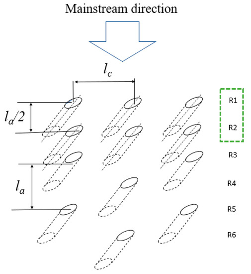
Figure 14.
Schematic of the improved arrangement.
Adopting the same boundary conditions and model settings as in the above calculation cases in Section 4.2, the calculation results are obtained. Figure 15 shows the contours of the inner wall temperature obtained with the improved arrangement (hereinafter referred to as arrangement “d”) and the comparison with the original three arrangements. It is obvious that the improved arrangement has the lowest inner wall temperature overall. In particular, the wall temperature substantially decreases over a certain distance from the inlet compared with the original three arrangements.
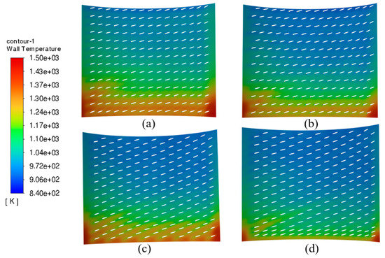
Figure 15.
Temperature contours of the inner wall under the improved arrangement and the original three arrangements. (a) Arrangement “a”, (b) Arrangement “b”, (c) Arrangement “c”, (d) Arrangement “d”.
The distribution of the comprehensive cooling efficiency (, where is the temperature of the outer wall) along the axial direction of the liner wall for the various cooling hole arrangements can be obtained by taking the centerline between two adjacent columns of cooling holes in the axial direction of the outer wall as the object of study, and the points on the centerline can basically represent the worst cooling effectiveness points of the liner wall. Figure 16 shows the distribution of the comprehensive cooling efficiency along the axial direction for the improved arrangement and the comparison with the original three arrangements. Within a long distance from the liner entrance, i.e., section “A” in Figure 15, the comprehensive cooling efficiency of arrangement “c” is lower than that of arrangement “b”. However, after optimization, the comprehensive cooling efficiency for the liner wall is greatly improved and higher than that of arrangement “b”. In Figure 15, in section “B”, the comprehensive cooling efficiency of arrangement “d” slowly grows but is still higher than that of the other arrangements before optimization, while in section “C”, i.e., approximately 15 mm from the exit, the cooling efficiency after optimization begins to slowly drop and becomes lower than that in arrangement “c”. The main reason is that after optimization, the number of cooling holes in the front section of the combustor liner increases, while the amount of cooling air entering the liner from the back section of the liner decreases under the same overall cooling airflow, resulting in lower cooling efficiency in section “C”.
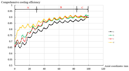
Figure 16.
Comparison of the comprehensive cooling efficiencies for the liner wall under the improved cooling hole arrangement and the original three arrangements.
The average temperatures of the inner and outer walls under the improved arrangement are obtained and compared with those under the three arrangements before optimization, as shown in Figure 17. It is obvious that after optimization, the average temperatures of the inner and outer walls of the liner are substantially lower than those for any of the other arrangements before optimization, which reflects the effectiveness of the improved method.
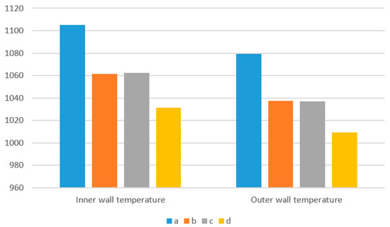
Figure 17.
Comparison of the average inner and outer wall temperatures under the improved cooling hole arrangement and the original three arrangements.
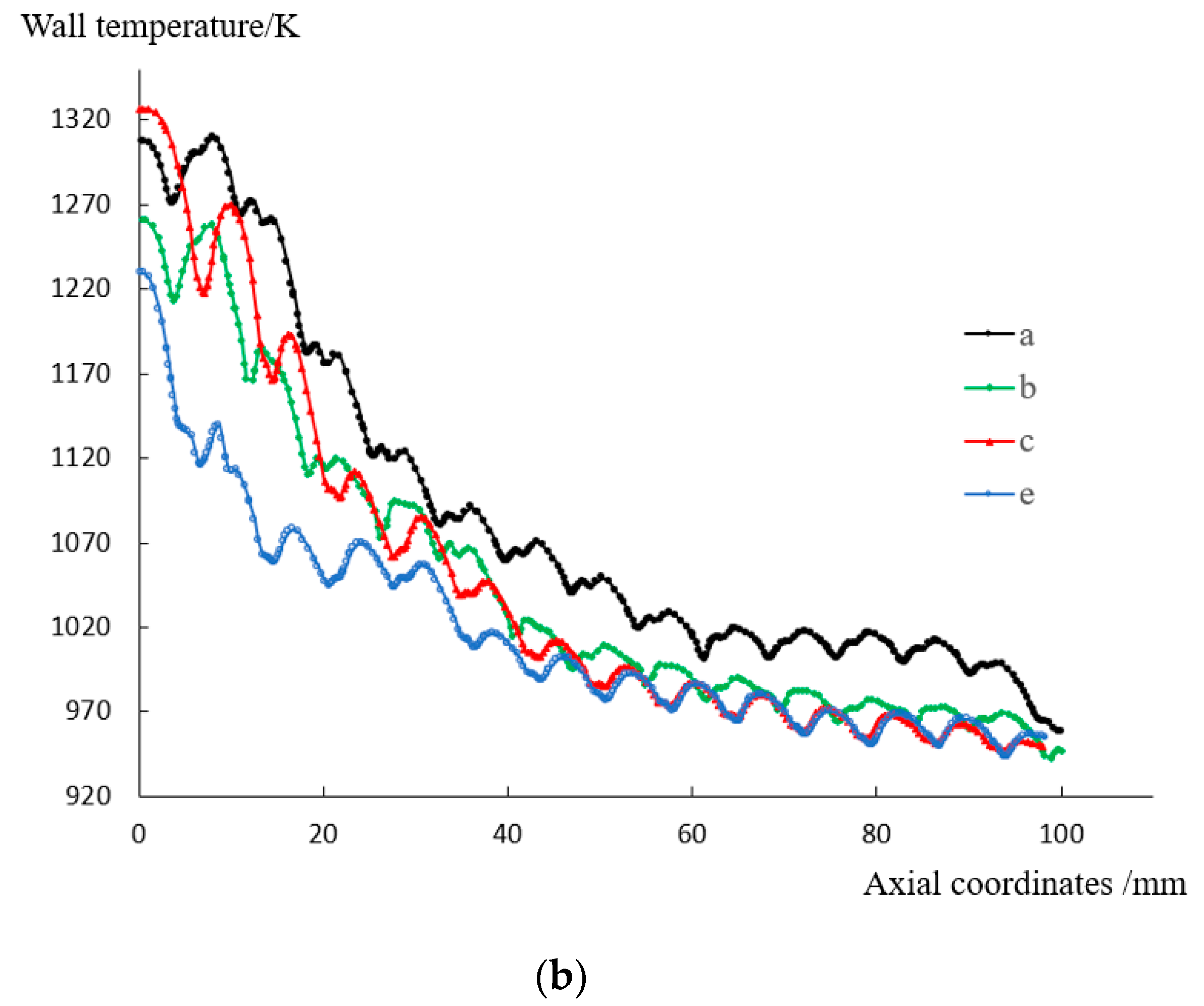
The distributions of the wall temperatures on the inner wall and outer wall under the four arrangements are shown in Figure 18. It can be seen that the temperatures of the inner and outer walls in the first half of the liner under the improved arrangement “d” have been sharply decreased comparing to the base arrangement “c”, and they are also substantially lower than those of the other arrangements. The maximum local temperature is decreased from 1330 K to 1235 K, which is already lower than the long-term operating limited temperature of nickel-based high-temperature alloys, such as GH5188.
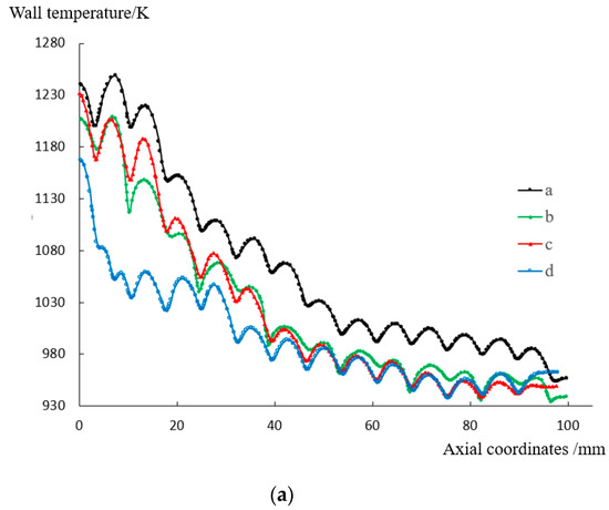
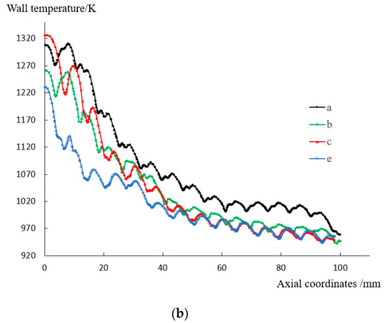
Figure 18.
Distribution of the wall temperatures on the inner and outer wall under the improved cooling hole arrangement and the original three arrangements: (a) inner wall; and (b) outer wall.
5. Conclusions
Based on the above research and analysis, the following conclusions can be reached:
- For the tangential effusion cooling, the cooling jet flows spirally onwards and tightly adheres to the inner surface after entering the liner, and it is then distributed in a divergent “horsetail” shape on the inner wall of the liner. For the traditional effusion cooling of a flat plate, most of the cooling jets quickly integrate into the mainstream.
- For the tangential effusion cooling, intensive heat and mass exchange occur mainly at the zone around the upper edge/lip of the cooling hole exit. An appropriate arrangement of cooling holes could make the cooling jet tightly “compressed” by the upstream jets, which reduces the turbulence intensity around the cooling jets, thus reducing the heat and mass exchange between the cooling jets and mainstream, and increasing the cooling effectiveness.
- The temperature of the liner wall near a cooling hole is higher than the temperature of the cooling film formed on the inner wall surface, indicating that for this type of cooling, the increase in the liner wall temperature mainly comes from the radiation heat transfer from the high-temperature mainstream, and the convective heat transfer direction between the wall and the cooling film is from the wall to the film.
- Three different arrangements of cooling holes are compared, and the unit cooling area of a hole is defined. It is found that and the distances between an upstream jet and the downstream adjacent jets S1 and S2 have a great influence on the cooling efficiency. The axially staggered 1/2 column arrangement has the highest comprehensive cooling efficiency due to the smallest and the smallest variance in S1 and S2.
- Based on the theoretical analysis and comparative studies, the cooling hole arrangement is improved based on the axially staggered 1/2 column arrangement (arrangement “c”), i.e., the first and second rows of cooling holes are doubled. The calculation results show that this improvement method significantly increases the cooling efficiency for the liner wall without increasing the flow rate of the cooling air, and the maximum local temperature is decreased from 1330 K to 1235 K, which is already lower than the long-term operating limited temperature of nickel-based high-temperature alloys, such as GH5188.
Author Contributions
Investigation and writing, Z.L., review and editing, P.X., Q.Z. and X.C. All authors have read and agreed to the published version of the manuscript.
Funding
This research was funded by the Tsinghua Universtiy Initiative Scientific Research Program and the Science Center for Gas Turbine Project (NO. 2022-a-II-005).
Data Availability Statement
Data is unavailable due to privacy.
Conflicts of Interest
We declare that there are no conflict of interest.
Nomenclature
| D | Inner diameter of the combustor liner, mm |
| D1 | Inner diameter of the combustor case, mm |
| T | Temperature, K |
| V | Velocity, m/s |
| Inclination angle | |
| Tangential angle | |
| la | Axial spacing of holes |
| n | Number of adjacent nearest holes |
| S1 | Distance between an upstream cooling jet and an adjacent downstream cooling jet |
| Variance in and | |
| L | Length of the combustor liner, mm |
| m | Mass flow rate, kg/s |
| P | Total pressure, Pa |
| d | Diameter of effusion holes, mm |
| Compound angle | |
| lc | Circumferential spacing of holes |
| A | Area enclosed between adjacent holes |
| Unit cooling area of a hole | |
| S2 | Distance between an upstream cooling jet and the other adjacent downstream cooling jet |
| Subscripts | |
| w | Wall |
| h | Hot |
| c | Cold |
References
- Baocheng, Z. Status and Development of Aeroengine Combustors. Aeroengine 2013, 39, 67–73. [Google Scholar]
- Chuanliang, Z.; Yao, H.; Hongyu, M.; Shoutang, S.H.N. Development and Application of Heat Resisting Techniques for Gas Turbine Combustor Liner. Aeroengine 2016, 42, 47–54. [Google Scholar]
- Lefebvre, A.; Ballal, D. GAS Turbine Combustion; CRC Press: Boca Raton, FL, USA, 2010. [Google Scholar]
- Rushan, J.; Jianqin, S. Advanced Gas Turbine Combustor; Aviation Industry Press: Beijing, China, 2016. [Google Scholar]
- Pengfeng, Z.; Wenzhe, C. A Review of Advanced Cooling Technology for Combustor Based on Micro-hole. Tactical Missile Technol. 2018, 2, 95–101. [Google Scholar]
- Shumin, W. Advanced Gas Turbine Combustor Design and Development; Shanghai Jiao Tong University Press: Shanghai, China, 2014. [Google Scholar]
- Click, A.; Ligrani, P.M.; Hockensmith, M.; Knox, J.; Larson, C.; Fairbanks, A.; Liberatore, F.; Patel, R.; Ho, Y.-H. Louver Slot Cooling and Full-Coverage Film Cooling With a Combination Internal Coolant Supply. ASME Trans. J. Turbomach. 2021, 143, 031004. [Google Scholar] [CrossRef]
- Bergeles, G.; Gosman, A.D.; Launder, B.E. Double-Row Discrete Holes Cooling: An Experimental an Numerical Study. ASME J. Eng. Power 1980, 102, 498–503. [Google Scholar] [CrossRef]
- Afejuku, W.O.; Hay, N.; Lampard, D. The film cooling effectiveness of double rows of holes. J. Eng. Power Trans. ASME 1980, 102, 601–607. [Google Scholar] [CrossRef]
- Kadotani, K.; Goldstein, R.J. Effect of Mainstream Variables on Jets Issuing from a Row of Inclined Round Holes; ASME Paper No. 78-GT-138; ASME: New York, NY, USA, 1978. [Google Scholar]
- Brown, A.; Saluja, C.L. Film Cooling from Three rows of Holes on Adiabatic, Constant Heat Flux and Isothermal Surfaces in the Presence of Variable Velocity Gradients and Turbulent Intensity; ASME Paper No.79j-GT-24; American Society of Mechanical Engineers: New York, NY, USA, 1979. [Google Scholar]
- Wang, J.; Hu, Z.; Du, C.; Tian, L.; Baleta, J. Numerical study of effusion cooling of a gas turbine combustor liner. Fuel 2021, 294, 120578. [Google Scholar] [CrossRef]
- Wei, H.; Zu, Y.; Ai, J.; Ding, L. Experimental study on the full-coverage film cooling of fan-shaped holes with a constant exit width. Int. J. Heat Mass Transf. 2019, 140, 379–398. [Google Scholar] [CrossRef]
- Zong, C.; Ji, C.; Cheng, J.; Zhu, T. Comparison of adiabatic and conjugate heat transfer models on near-wall region flows and thermal characteristics of angled effusion cooling holes. Therm. Sci. Eng. Prog. 2022, 30, 101269. [Google Scholar] [CrossRef]
- Goldstein, R.J.; Jin, P. Film Cooling Downstream of a Row of Discrete Holes with Compound Angle. J. Turbomach. 2001, 123, 222–230. [Google Scholar] [CrossRef]
- Chen, P.H.; Hung, M.S.; Ding, P.P. Film Cooling Performance on Curved Walls with Compound Angle Hole Configuration. Ann. New York Acad. Sci. 2010, 934, 353–360. [Google Scholar] [CrossRef]
- Natsui, G.; Claretti, R.; Ricklick, M.A.; Kapat, J.S.; Crawford, M.E.; Brown, G.; Landis, K. Experimental Evaluation of Large Spacing Compound Angle Full-Coverage Film Cooling Arrays: Adiabatic Film Cooling Effectiveness. J. Turbomach. 2016, 138, 071001. [Google Scholar] [CrossRef]
- Ekkad, S.V.; Zapata, D.; Han, J.C. Film Effectiveness over a Flat Surface with Air and CO2 Injection through Compound Angle Holes Using a Transient Liquid Crystal Image Method. J. Turbomach. 1997, 119, 587–593. [Google Scholar] [CrossRef]
- Lee, H.W.; Park, J.J.; Lee, J.S. Flow Visualization and Film Cooling Effectiveness Measurements around Shaped Holes with Compound Angle Orientations. Int. J. Heat Mass Transf. 2002, 45, 145–156. [Google Scholar] [CrossRef]
- Michel, B.; Gajan, P.; Strzelecki, A.; Savary, N.; Kourta, A.; Boisson, H.-C. Full coverage film cooling using compound angle. C. R. Mécanique 2009, 337, 562–572. [Google Scholar] [CrossRef]
- Walters, D.K.; Leylek, J.H. A Detailed Analysis of Film–Cooling Physics: Part I—Streamwise Injection with Cylindrical Holes. J. Turbomach. 2000, 122, 102–112. [Google Scholar] [CrossRef]
- McGovern, K.T.; Leylek, J.H. A Detailed Analysis of Film Cooling Physics: Part II—Compound-Angle Injection with Cylindrical Holes. J. Turbomach. 2000, 122, 113–121. [Google Scholar] [CrossRef]
- Hyams, D.G.; Leylek, J.H. A Detailed Analysis of Film Cooling Physics: Part III—Streamwise Injection with Shaped Holes. J. Turbomach. 2000, 122, 123–132. [Google Scholar] [CrossRef]
- Brittingham, R.A.; Leylek, J.H. A Detailed Analysis of Film Cooling Physics: Part IV—Compound–Angle Injection with Shaped Holes. J. Turbomach. 2000, 122, 133–145. [Google Scholar] [CrossRef]
- Chin, J. Design of Aero Engine Lean Direct Mixing Combustor. In Proceedings of the 2018 Joint Propulsion Conference, Cincinnati, OH, USA, 9–11 July 2018. [Google Scholar] [CrossRef]
- Chin, J. Suggestions on High Temperature Rise Combustor. In Proceedings of the AIAA Propulsion and Energy 2019 Forum, Indianapolis, IN, USA, 19–22 August 2019. [Google Scholar] [CrossRef]
- Chin, J.; Dang, J. New Generation Aero Combustor; Intech Open Access Publisher: Vienna, Austria, 2020. [Google Scholar]
- Wang, T.; Suo, J.; Liang, H. Numerical study of tangential effusion cooling for combustor liner. J. Aerosp. Power 2011, 26, 1052–1058. [Google Scholar]
- Guang, Y.; Weiwei, S.; Zhedian, Z. Experimental and numerical study on heat transfer characteristics of tangential effusion cooling for a combustor liner. Appl. Therm. Eng. 2023, 218, 119374. [Google Scholar]
- Xinshuo, D. Fluent 17.0 Fluid Simulation: From Beginner to Proficient; Tsinghua University Press: Beijing, China, 2018. [Google Scholar]
- Qinghua, Z.; Yixiang, Y. Flow dynamics of dual-stage counter-swirl combustor in different confinement spaces. Int. Commun. Heat Mass Transf. 2020, 116, 104633. [Google Scholar]
- Li, Z.; Yuan, Y.; Guo, B.; Varsegov, V.L.; Yao, J. The Recirculation Zone Characteristics of the Circular Transverse Jet in Crossflow. Energies 2020, 13, 3224. [Google Scholar] [CrossRef]
- Kwon, H.; Ligrani, P.M.; Vanga, S.R.; Park, H. Flow structure and surface heat transfer from numerical pre-dictions for a double wall effusion plate with impingement jet array cooling. Int. J. Heat Mass Transf. 2022, 183, 122049. [Google Scholar] [CrossRef]
- Hjärtstam, S.; Johansson, R.; Andersson, K.; Johnsson, F. Computational Fluid Dynamics Modeling of Oxy-Fuel Flames: The Role of Soot and Gas Radiation. Energy Fuels 2012, 26, 2786–2797. [Google Scholar] [CrossRef]
- Liu, Y.; Rao, Y.; Yang, L. Numerical simulations of a double-wall cooling with internal jet impingement and external hexagonal arrangement of film cooling holes. Int. J. Therm. Sci. 2020, 153, 106337. [Google Scholar] [CrossRef]
- Ji, Y.; Ge, B.; Zang, S. Analysis of effusion cooling under realistic swirl reacting flow in gas turbine combustor. Appl. Therm. Eng. 2022, 216, 119101. [Google Scholar] [CrossRef]
- Venkatesh, V.; Sriraam, J.; Subhash, K.; Velamati, R.K.; Srikrishnan, A.R.; Ramakrishnananda, B.; Batchu, S. Studies on effusion cooling: Impact of geometric parameters on cooling effec-tiveness and coolant consumption. Aerosp. Sci. Technol. 2018, 77, 58–66. [Google Scholar] [CrossRef]


Disclaimer/Publisher’s Note: The statements, opinions and data contained in all publications are solely those of the individual author(s) and contributor(s) and not of MDPI and/or the editor(s). MDPI and/or the editor(s) disclaim responsibility for any injury to people or property resulting from any ideas, methods, instructions or products referred to in the content. |
© 2023 by the authors. Licensee MDPI, Basel, Switzerland. This article is an open access article distributed under the terms and conditions of the Creative Commons Attribution (CC BY) license (https://creativecommons.org/licenses/by/4.0/).