Abstract
The Mahu conglomerate reservoir is characterized by strong heterogeneity and the uneven stimulation of the horizontal lateral during hydraulic fracturing. The optimization of the perforation number per cluster is of great value for horizontal well multi-stage fracturing (HWMF) because the suitable perforation number not only promotes the uniform propagation of multiple fractures but also prevents excessive perforation erosion. In this work, a typical well in the Mahu conglomerate reservoir was selected, and a field test of optimizing the perforation number was carried out. The perforation schemes of three, five, and eight perforations per cluster were designed in nine fracturing stages, respectively. The wellhead pressure under different perforation schemes was compared and analyzed with the step-down flow rate test, and the optimal perforation number per cluster in the Mahu conglomerate reservoir was selected as eight. The theoretical calculation results show that eight perforations per cluster can generate the perforation friction of 5 MPa, sufficient to overcome the mechanical property differences among multiple clusters within one stage. The downhole video technology shows that the perforation erosion area is the most uniform with the case of eight perforations per cluster. Moreover, the optical fiber monitoring results show that the perforation number of eight per cluster can realize the simultaneous initiation and uniform propagation of six fractures or five fractures within one stage. This work is of great significance for the efficient development of the Mahu conglomerate reservoir through HWMF.
1. Introduction
The Mahu conglomerate reservoir is located in the northwest margin of Junge Basin, with an area of nearly 5000 km2 []. The third-level reserve is more than 1 billion tons. It is one of the most important substitute areas for increasing storage and production in China. The Mahu conglomerate reservoir has low porosity and low permeability. The average measured permeability is 0.05–0.46 mD, and the average porosity is 7.8–12%. Horizontal well multi-stage fracturing (HWMF) is one of the necessary techniques used to economically develop such resources []. In the Mahu conglomerate reservoir, the horizontal stress difference is beyond 20 MPa. It lacks natural fractures; thus, it is difficult to obtain the volume stimulation effect naturally []. It is necessary to reduce the construction cost and create an ‘intensive fracturing’ effect. Multiple perforation clusters with close space are usually arranged in one fracturing stage. In this way, it can generate multiple hydraulic fractures simultaneously []. However, the reservoir of the Mahu conglomerate is highly heterogeneous. Mahu conglomerate reservoirs are rich in gravel. The gravel content and size highly affect the physical and mechanical properties. The cementation and the support pattern determine the injection pressure and the overall fracture geometry. Hydraulic fractures can cross, bypass, or stop at the gravel. Therefore, the Mahu conglomerate reservoirs are highly heterogeneous and the treatment parameters in the homogeneous reservoirs cannot be applied directly [,]. It is difficult to realize the simultaneous initiation of multiple perforation clusters within a stage. Uneven propagation within one stage dramatically restricts the efficient development of such resources [].
Limited entry fracturing (LEF) is widely used during horizontal well multi-stage fracturing (HWMF). The throttling perforation friction can be effectively enhanced by reducing the perforation number per cluster, and the LEF technique can promote the simultaneous initiation and uniform propagation of multiple fractures []. The perforation density is usually 16 perforations/m. By changing the perforation length, the perforation number per cluster in the conventional scheme is 16–24, while the perforation number per cluster in the LEF scheme is 8–12, and the perforation number per cluster in the extremely limited entry fracturing (XLEF) scheme is 2–6 []. It is of great value to determine the perforation number per cluster during HWMF in the Mahu conglomerate reservoirs. On the one hand, the proper perforation number per cluster can avoid the excessive erosion of perforations and super fractures induced by the proppant. On the other hand, the perforation throttling friction can be enhanced enough to overcome the mechanical differences among multiple clusters within one stage, and the uniform propagation of multiple fractures can be obtained []. The reported investigations mainly applied numerical methods to optimize the perforation parameters of the HWMF. Wu et al. [] studied the effect of perforation density on the fracture morphology within one stage of four perforation clusters based on the displacement discontinuity method (DDM). It shows that reducing the perforation number of the side clusters can significantly improve fracture uniformity. Lu et al. [] established a 3D fluid–solid fully coupled multiple-fracture competitive propagation model. The influence of the perforation friction on the multiple fracture geometry was investigated. It shows that when the perforation friction is beyond 7.5 MPa, the differences among multiple fractures can be neglected and the fracturing fluid can evenly flow into each fracture. Based on the CZM model and Bernoulli equation, Li et al. [] established a finite element model to investigate the initiation and propagation of multiple fractures influenced by the perforation number and diameter. Some suggestions have been provided for the LEF design. Zhou et al. [] applied the pseudo-three-dimensional model to explore the relationship between fracture distribution and fluid injection pressure. The perforation equivalent diameter was optimized and the perforation guns were selected for the LEF technique. Zhang et al. [] carried out large-scale true triaxial experiments to investigate the effects of perforation length, perforation density, perforation diameter, and perforation phase on the fracture morphology and injection pressure. It provided theoretical support for the optimization of perforation parameters during HWMF.
The numerical and experimental models for perforation optimization are generally homogeneous and quite different from the real reservoir properties. The optimized perforation parameters cannot directly guide the LEF design for the Mahu conglomerate reservoir. This work optimized the perforation parameter based on the perforation friction model. Moreover, a real HWMF well in the Mahu conglomerate reservoir was selected and nine fracturing stages were designed with different perforation numbers per cluster. Based on the step-down test, the injection pressure under different perforation numbers was explored to optimize the perforation number. The optical fiber monitoring technology verified the optimization results. This work can provide reliable guidance for the design of LEF in the Mahu conglomerate reservoir.
2. Perforation Optimization Based on the Theoretical Model
The limited entry fracturing (LEF) technique was first proposed in 1963. The key points are: reducing the total number of perforations within one stage, maintaining a high fluid injection rate, generating large perforation friction, and balancing the fluid flow among multiple perforation clusters. During HWMF, perforation erosion cannot be avoided due to the injection of a large amount of proppant, and the perforation friction is gradually weakened. This results in a heel fracture propagation much larger than that of the toe fracture, and the horizontal lateral cannot be stimulated mutually [,,]. Moreover, there are usually 5–10 perforation clusters within one stage. The perforation cluster number per stage should adapt to the capability of the fracturing trucks. Increasing the perforation number per stage can decrease the number of fracturing treatments and lower the treatment cost. It is challenging to promote the uniform propagation of multiple fractures. Therefore, the optimization of the perforation number is necessary and the above factors should be considered. In this way, the reservoir can be fully cut and the treatment cost can be significantly reduced. However, the smaller the cluster spacing, the greater the interference stress among multiple fractures, and the more serious the nonuniformity of the fluid distribution. The Mahu conglomerate reservoir has strong heterogeneity and stress interference, and the conventional LEF cannot balance the mechanical differences among multiple perforation clusters. Some researchers put forward the extremely limited fracturing (XLEF) technique. Somanchi [] and Weddle [] et al. reported that when the perforation number per cluster is 2–3, the perforation can reach up to 15 MPa, which is enough to balance the effect of the reservoir heterogeneity and the uniform fluid distribution among multiple fractures can be realized. There are usually 8–12 perforations per cluster in terms of LEF and 2–7 perforations per cluster in terms of XLEF. The perforations are spirally distributed along the wellbore for LEF and symmetrically distributed for XLEF.
The perforation friction calculation model is as follows []:
where i is the number of the fracture cluster i; is the fluid friction flowing into the perforation, MPa; Qi is the fluid velocity into the fracture i, m3/min; αp is the frictional coefficient dimensionless; ρ is the fluid density, g/cm3; Np,i is the perforation number before erosion, dimensionless; Dp,i is the perforation diameter, mm; C is the flow coefficient, dimensionless, ranging from 0.56 (before proppant erosion) to 0.90 (after proppant erosion).
The reliability of the model was verified against the experimental test. As shown in Figure 1, when the perforation coefficient is selected as 0.7, the perforation friction based on Equation (1) is consistent with that from the experimental test. The fluid injection rate per perforation is 0.9 m3/min and the proppant concentration is 180 kg/m3. The model is simple and considers the effects of the perforation diameter, the perforation number, the fluid injection rate, and the fluid density. The initial perforation parameter can be quickly optimized based on Equation (1).
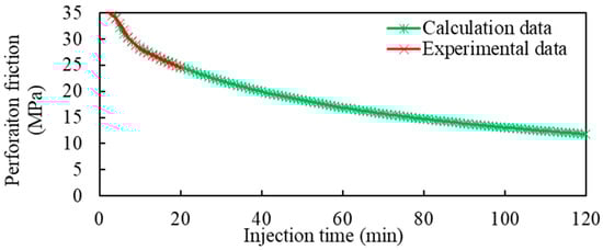
Figure 1.
The verification of the perforation friction calculation model.
This work selects nine fracturing stages and each stage has six perforation clusters along one horizontal well in the Mahu Conglomerate reservoir. The pump injection rate is 10 m3/min, 12 m3/min, and 14 m3/min. In the past 3 years, the perforation numbers three, five, and eight are the most commonly used designs in Mahu conglomerate reservoirs. It remains unclear which is the optimal design. In this work, the perforation number per cluster is designed as three, five, and eight for the nine fracturing stages, and the perforation diameter is identical to 10 mm.
Figure 2 gives the perforation friction calculation results based on Equations (1) and (2). The perforation friction increases with the fluid infection rate and decreases with the perforation number. When the perforation number within one stage is less than 30 (4 perforations per cluster), the perforation friction is significantly affected by the perforation number; when it is beyond 30, the effect of perforation number on the perforation friction can be neglected. As for the perforation number of 3 per cluster (total 18 perforations within one stage), the perforation frictions are, respectively, 39.6 MPa, 44.1 MPa, and 60 MPa, corresponding to fluid injection rates of 10 m3/min, 12 m3/min, and 14 m3/min. As for the perforation number of 5 per cluster (total 30 perforations within one stage), the perforation frictions are, respectively, 11.0 MPa, 15.9 MPa, and 21.6 MPa, corresponding to fluid injection rates of 10 m3/min, 12 m3/min, and 14 m3/min. As for the perforation number of 8 per cluster (total 48 perforations within one stage), the perforation frictions are, respectively, 4.3 MPa, 6.2 MPa, and 8.4 MPa, corresponding to fluid injection rates of 10 m3/min, 12 m3/min, and 14 m3/min. Therefore, the perforation friction will be beyond 5 MPa considering part of the perforations receive no fracturing fluid when the perforation number per cluster is designed as eight.
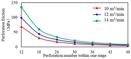
Figure 2.
Calculation of the initial perforation friction with different fluid injection rates.
3. Experimental Design
3.1. The Properties of the Test Well
Mahu conglomerate reservoir has a large reserve volume and is located in the northwest region of China. It is rich in gravel and has low permeability and low porosity. The large scale of hydraulic fracturing is necessary to economically develop the oil resources. The test well (Well A) is located at the Mahu conglomerate reservoir and the target formation is T1b32. The vertical depth of Well A is 2721.76 m, the measured depth is 4850 m, and the horizontal length is 1940 m. The rock lithology is mainly medium gravels and there are also some small and fine gravels. The average gravel content and sand content are, respectively, 66.0% and 29.7%. The effective porosity is 7.39–7.66% and the formation permeability is 0.93–0.97%. It has the characteristics of moderate-to-weak salt sensitivity, strong stress sensitivity, and weak-to-moderate water sensitivity. Natural fractures are not developed. Well logging data show that drilling-induced fractures are developed.
3.2. Perforating Scheme
A comparative test was carried out for the 7th to 15th stage (9 fracturing stages) of well A. The nine fracturing stages were all designed as 6 clusters per stage. The proppant volume per stage was designed as 25 m3 and the fluid injection rate was identical to 12 m3/min. To eliminate the influence of the spatial randomness, as shown in Table 1, the perforation number per cluster in stages 7, 10, and 13 were, respectively, designed as 3; the perforation number per cluster in stages 8, 11, and 14 were, respectively, designed as 5; the perforation number per cluster in stages 9, 12, and 15 were, respectively, designed as 8.

Table 1.
Perforation scheme of well A.
4. Analysis of Test Results
4.1. Analysis of the Step-Down Test Results
The step-down test is carried out after the completion of the proppant injection. The maximum fluid injection rate decreases gradually with four to five stages. At each stage, the fluid injection rate and the injection pressure are collected when the fluid injection pressure is stable. The near-wellbore friction and the perforation friction can be obtained based on the step-down test. In this work, after the completion of the proppant addition, the step-down tests were carried out by reducing the fluid injection rate with several steps. The fluid injection pressure was collected and compared for different perforation numbers. Figure 3 gives the fluid injection pressure curves with the fluid injection rate for the perforation numbers three, five, and eight, respectively. The red lines represent the fluid injection pressure and the green lines represent the fluid injection rate. The points of the stable injection pressure for each fluid injection rate were collected. Comparing the fluid injection pressure of the same fluid injection rate, the effect of the perforation number on the perforation friction can be discovered and the optimal perforation number can be determined.
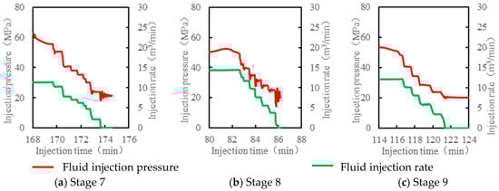
Figure 3.
Curve of step-down displacement under different perforation parameters.
Figure 4 gives the scatter diagram of the fluid injection pressure and the fluid injection rate with different perforation numbers. The data points marked three perforations and include the test results of the 7th, the 10th, and the 13th stage; the data points marked five perforations and include the test results of the 8th, the 11th, and the 14th stage; the data points marked three perforations and include the test results of the 9th, the 12th, and the 15th stage. Figure 4 shows that when the fluid injection rate reduces to 0 m3/min, the injection pressure is about 20 MPa, which reflects that the fracture closure pressures for all perforation schemes are the same. The reason is the horizontal minimum principal stresses for the nine stages have a negligible difference. Moreover, the higher the fluid injection rate, the larger the difference in the fluid injection pressure for different perforation schemes. When the fluid injection rate is less than 6 m3/min, the fluid injection pressures are almost the same.
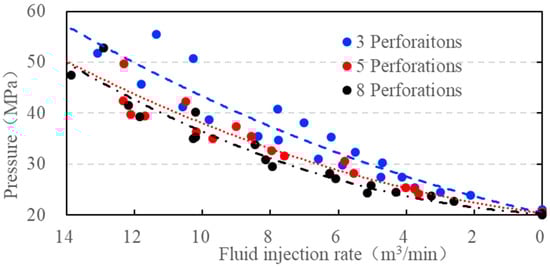
Figure 4.
Relationship between the injection pressure and pumping rate under different perforation parameters.
By comparison, the perforation friction of the three-perforation scheme is higher than that of the eight-perforation scheme. According to Equations (1) and (2), when the fluid injection rate is 12 m3/min, the perforation frictions are, respectively, 44.1 MPa and 6.2 MPa for the three-perforation and eight-perforation schemes, with a difference of about 38 MPa. According to Figure 4, when the fluid injection rate is 12 m3/min, the fluid injection pressures are, respectively, 50 MPa and 45 MPa for the three-perforation and eight-perforation schemes, with a difference of about 5 MPa. During HWMF, a large amount of proppant needs to be injected and the perforations will be inevitably eroded, the perforation friction will be highly reduced, and the LEF technique loses its effect. HWMF is a tremendous task because 10–20 thousand cubic meters of fluids and 2–3 thousand cubic meters of proppant will be injected into one horizontal well. For a given horizontal well, the lateral length is 1000 m and 10 fracturing stages are designed. There are 6 perforation clusters and 48 perforations. One perforation can receive 3–5 cubic meters of proppant. Therefore, the residual perforation frictions for different perforation schemes are almost identical. It is not necessary to extremely reduce the perforation number in the Mahu conglomerate reservoir. Moreover, when the perforation number per cluster is three, it is easy to cause excessive perforation erosion and the dominant cluster will receive more fracturing fluid. This can cause single fracture outbursts and super fractures. Therefore, to obtain the ideal initial perforation friction and avoid a single fracture outburst, it is suggested that the perforation number per cluster should be eight for the HWMF with six clusters per stage in the Mahu conglomerate reservoir.
4.2. Analysis of Perforation Erosion Measurements
Downhole video technology was applied to monitor the perforation erosion status of different perforation schemes. Figure 5 gives the array side view camera. It includes four orthogonally mounted lenses able to simultaneously capture four video streams with full 360° coverage of the wellbore. Compared with the previous generation of the single sideview lens rotary camera system, one primary benefit is a significantly reduced acquisition time as there is no longer a time-consuming requirement to individually locate perforations and then accurately position the camera at the required depth before rotating the lens to capture the perforation image at the correct phase []. As shown in Figure 6, it can be seen that when the perforation number per cluster is three, the perforation erosion area of cluster 6 in stage 7 and cluster 4 in stage 13 is small, indicating receiving a small amount of proppant. When the perforation number per cluster is five, the perforation erosion area of cluster 6 in stage 11 and cluster 5 in stage 14 is large, indicating receiving an excessive amount of proppant. When the perforation number per cluster is eight, the perforation erosion area in the 9th, 12th, and 15th stages is more balanced. In this way, each perforation cluster receives the average amount of proppant and the fracturing stage will contribute to a higher oil production profile. The perforation number per cluster of eight is an optimal scheme in the Mahu conglomerate reservoir.
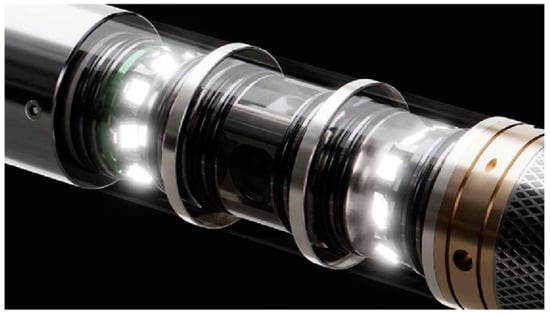
Figure 5.
Statistical diagrams of perforation erosion area under different perforation parameters.
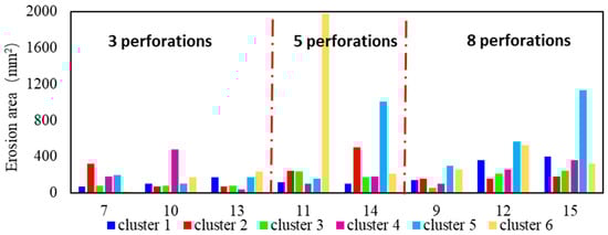
Figure 6.
Statistical diagrams of perforation erosion area under different perforation parameters.
5. Verification of Optimized Perforation Scheme
In this part, Well B in the Mahu conglomerate reservoir was selected and the optical fiber (OF) technology was applied to monitor the fluid distortion among multiple fractures in real time []. The vertical depth of Well B is 3858.77 m and the horizontal length is 1066.0 m. Well B is located in the fault block of the Jinlong area. The reservoir lithology is mainly lithic sandstone, followed by feldspar lithic sandstone; the porosity is 5.8–17.3%, with an average of 12.3%. The permeability is 0.01–347.0 mD, with an average of 1.21 mD. Natural fractures are not developed. To fully cut the reservoir and save cost, there are four to six perforation clusters within one stage and the cluster spacing is 15–25 m. The fluid injection rate is 10–12 m3/min. This part mainly verified whether multiple fractures can initiate simultaneously and propagate uniformly with the perforation number of eight per cluster.
The optical fiber (OF) technology records the vibration and acoustic waves generated from the fracturing fluid injection and the fluid flow rate and volume can be analyzed after the inversion. OF is more sensitive to vibration and acoustic waves than temperature, so it can identify fracturing injection sites (perforation clusters) at higher resolution. Two fracturing stages of well B are selected. There are six perforation clusters in the 11th stage and five perforation clusters in the 14th stage. The perforation number per cluster is eight for both stages. As shown in Figure 7 for section (a), when the fluid injection rate is 8 m3/min, each perforation cluster can receive fluid, while the intensity of the acoustic signal has an obvious difference. The first cluster and the second cluster have strong acoustic signals. When the fluid injection rate reaches up to 10 m3/min (Figure 7 for section (b)), the fluid distribution among multiple fractures is more uniform and the horizontal lateral can be stimulated effectively. With the continuous injection of the proppant, the perforations are gradually eroded, and the LEF effect is reduced. After the injection of 80 kg proppant, some perforation clusters no longer receive fracturing fluid, resulting in uneven fracture propagation in the later stage (Figure 7 for section (c)). Temporary plugging technology (TPT) can plug the erosion perforations by injection of the diverters. In this way, multiple fractures can receive the same amount of proppant during the sand-adding stage [].
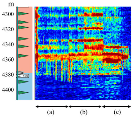
Figure 7.
Optical fiber monitoring results of Stage 11.
As shown in Figure 8 for section (a), when the fluid injection rate is 8 m3/min, perforation clusters 1–4 can receive fluid, while the fluid volume entering into cluster 5 is small. As shown in Figure 8 for section (b), when the fluid injection rate is 10 m3/min, the acoustic signals of clusters 2 to 5 are enhanced and the fluid distribution is more uniform, while the acoustic signal of cluster 1 is weakened. With the continuous proppant injection, the acoustic signal of cluster 3 is firstly weakened, followed by cluster 4 (Figure 8 for section (c)). This indicates that the perforation erosion reduces the flow-limiting effect with a dynamic process. Therefore, the perforation number of eight can effectively avoid generating super fractures and promote more than 80% of the perforating clusters to receive fracturing fluid.
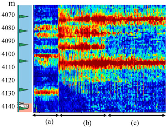
Figure 8.
Optical fiber monitoring results of Stage 14.
This work integrates the theoretical model, the injection pressure analysis, downhole video technology, and optical fiber technology to optimize the perforation parameters. The reported research focuses on numerical simulation and laboratory experiments. It has a gap with the real fracturing conditions. The theoretical model is verified with the field test. Downhole video technology can obtain pictures of the perforations. The optical fiber technology can monitor fluid distribution in real-time. This work selects the real fracturing well in the Mahu conglomerate reservoir and the optimized parameters are reliable. The design of eight perforations per cluster cannot be applied to other reservoirs directly. The effect of LEF is highly influenced by the reservoir heterogeneity, the dosage of the proppant, the material of the casing, and the fluid injection rate. This work mainly optimized the perforation parameter for the Mahu conglomerate reservoirs. However, the optimization method can be applied to any reservoir.
6. Conclusions
To optimize the perforation number of HWMF in the Mahu conglomerate reservoir, this paper selects the actual fracturing wells and conducts comparative perforation tests. The downhole video technology and the optical fiber technology were applied to monitor the stimulation effect with different perforation parameters. The main conclusions are as follows:
- (1)
- It is necessary to optimize the perforation number per cluster because it not only improves the net wellbore pressure of the wellbore and balances the property difference among multiple fractures but also avoids excessive perforation erosion. Multiple fractures can propagate uniformly through reducing the perforation number while the super fracture may generate if the perforation number is extremely small.
- (2)
- The initial perforation friction of the three-perforation scheme is much higher than that of the eight-perforation scheme. After the injection of proppant, the difference in the perforation friction between the two schemes gradually decreases due to the perforation erosion. Based on downhole video monitoring results, the stimulation effect of the eight-perforation scheme is much better than that of the three-perforation scheme. It is suggested that the perforation number per cluster should be designed as eight in the Mahu conglomerate reservoir.
- (3)
- The optical fiber monitoring results show that the eight-perforation scheme can realize the simultaneous initiation of multiple fractures and more than 80% of the perforation clusters can receive fracturing fluid. With the injection of proppant, some perforation clusters stop receiving fracturing fluid due to the perforation erosion. The temporary plugging technology can be applied to plug the dominant perforation clusters and promote the poor perforation cluster to receive enough fracturing fluid.
Author Contributions
Supervision, Q.F.; Formal analysis, Y.M.; Funding acquisition, J.W.; Investigation, L.C.; Resources, Z.Y.; Supervision, Y.X.; Validation, H.L.; Writing—original draft, B.W. All authors have read and agreed to the published version of the manuscript.
Funding
This work was funded by the Natural Science Foundation of Xinjiang Uygur Autonomous Region (2022D01B77), Karamay Innovative Environment Construction Plan (Innovative talents) project (NO. 20232023hjcxrc0037), the National Natural Science Foundation of China (No. 52104011), and the Research Foundation of China University of Petroleum-Beijing at Karamay (No. XQZX20210001).
Data Availability Statement
All the data have been added in the manuscript.
Acknowledgments
Thanks to the reviewers and the editors.
Conflicts of Interest
The authors declare no conflict of interest.
References
- Li, G.; Qin, J.; Xian, C.; Fan, X.; Zhang, J.; Ding, Y. Theoretical understandings, key technologies and practices of tight conglomerate oilfield efficient development: A case study of the Mahu oilfield, Junggar Basin, NW China. Pet. Explor. Dev. 2020, 47, 1275–1290. [Google Scholar] [CrossRef]
- Jiangwen, X.U.; Jianmin, L.I.; Yuanyue, W.; Kun, D.; Hong, J. Exploration and practice of volume fracturing technology in the horizontal well of Mahu tight conglomerate reservoirs. China Pet. Explor. 2019, 24, 241. [Google Scholar]
- Zhang, W.; Gao, Y.; Liang, L.X. Rock mechanics characteristics of conglomerate reservoir and its effects on fracturing treatment. Fault-Block Oil Gas Field 2021, 28, 5. [Google Scholar]
- Li, M.H.; Zhou, F.J.; Huang, G.P. A finite element simulation method for multi-fracture propagation in horizontal wells based on fluid pipe element. J. China Univ. Pet. Ed. Nat. Sci. 2022, 046, 105–112. [Google Scholar]
- Liu, J.; Ge, H.; Mou, S.; Wang, X.; Wang, J. Characterization of meso-structure of glutenite reservoirs by ultrasonic characteristics and the velocity heterogeneity. J. Pet. Sci. Eng. 2022, 208, 109436. [Google Scholar] [CrossRef]
- Liu, J.; Ge, H.; Zhang, Z.; Wang, X.; Wang, J. Influence of mechanical contrast between the matrix and gravel on fracture propagation of glutenite. J. Pet. Sci. Eng. 2022, 208, 109639. [Google Scholar] [CrossRef]
- Li, J.M.; Wu, B.C.; Zhao, H.Y. Adaptability of horizontal well volume fracturing to tight conglomerate reservoirs in Mahu oilfield. China Pet. Explor. 2019, 24, 10. [Google Scholar]
- Liao, S.M.; Sang, Y.; Song, Y.; Zeng, B.; Liu, W.; Yang, L. Research and field tests on staged fracturing technology for casing deformation stage in horizontal shale gas wells. Nat. Gas Ind. 2017, 37, 40–45. [Google Scholar]
- Barree, R.D. Potential Issues with Extreme Limited Entry in Horizontal Wells. In Proceedings of the Unconventional Resources Technology Conference (URTEC), Virtual, 20–22 July 2020; pp. 713–733. [Google Scholar] [CrossRef]
- Long, G.; Xu, G. The effects of perforation erosion on practical hydraulic-fracturing applications. SPE J. 2017, 22, 645–659. [Google Scholar] [CrossRef]
- Wu, K.; Olson, J.E. Mechanisms of Simultaneous Hydraulic-Fracture Propagation From Multiple Perforation Clusters in Horizontal Wells. SPE J. 2016, 21, 1000–1008. [Google Scholar] [CrossRef]
- Lu, W.J.; Sun, Z.L.; Liu, B.W. Optimization of Perforation Friction during Limited Fracturing in Jimsar Shale Oil Reservoir. J. Xi’an Shiyou Univ. Nat. Sci. Ed. 2022, 37, 49–57. [Google Scholar]
- Li, Y.; Deng, J.G.; Liu, W. Numerical simulation of limited entry technique in multi-stage and multi-cluster horizontal well fracturing. Fault-Block Oil Gas Field 2017, 24, 69–73. [Google Scholar]
- Zhou, Z.L.; Zhang, G.Q.; Xiong, W.X. Perforating parameter optimization of limit entry fracturing for horizontal wells. Fault-Block Oil Gas Field 2015, 22, 374–378. [Google Scholar]
- Zhang, R.X.; Hou, B.; Dan, Q.L. Parameter optimization of spiral perforations in horizontal well with tight sandstone reservoir. Chin. J. Geotech. Eng. 2018, 40, 2143–2147. [Google Scholar]
- Li, Q.; Zhang, C.; Yang, Y.; Ansari, U.; Han, Y.; Li, X.; Cheng, Y. Preliminary experimental investigation on long-term fracture conductivity for evaluating the feasibility and efficiency of fracturing operation in offshore hydrate-bearing sediments. Ocean. Eng. 2023, 281, 114949. [Google Scholar] [CrossRef]
- Li, Q.; Zhao, D.; Yin, J.; Zhou, X.; Li, Y.; Chi, P.; Han, Y.; Ansari, U.; Cheng, Y. Sediment Instability Caused by Gas Production from Hydrate-bearing Sediment in Northern South China Sea by Horizontal Wellbore: Evolution and Mechanism. Nat. Resour. Res. 2023, 32, 1595–1620. [Google Scholar] [CrossRef]
- Wang, F.; Liu, X.; Jiang, B.; Zhuo, H.; Chen, W.; Chen, Y.; Li, X. Low-loading Pt nanoparticles combined with the atomically dispersed FeN4 sites supported by FeSA-NC for improved activity and stability towards oxygen reduction reaction/hydrogen evolution reaction in acid and alkaline media. J. Colloid Interface Sci. 2023, 635, 514–523. [Google Scholar] [CrossRef] [PubMed]
- Somanchi, K.; Brewer, J.; Reynolds, A. Extreme Limited-Entry Design Improves Distribution Efficiency in Plug-and-Perforate Completions: Insights From Fiber-Optic Diagnostics. SPE Drill. Complet. 2018, 33, 298–306. [Google Scholar] [CrossRef]
- Weddle, P.; Griffin, L.; Pearson, C.M. Mining the Bakken II—Pushing the Envelope with Extreme Limited Entry Perforating. In Proceedings of the SPE Hydraulic Fracturing Technology Conference and Exhibition, The Woodlands, TX, USA, 23–25 January 2018. [Google Scholar]
- Cramer, D.; Friehauf, K.; Roberts, G.; Whittaker, J. Integrating DAS, treatment pressure analysis and video-based perforation imaging to evaluate limited entry treatment effectiveness. In Proceedings of the SPE Hydraulic Fracturing Technology Conference and Exhibition, OnePetro, Oklahoma City, OK, USA, 9–10 April 2019. [Google Scholar]
- Zang, C.; Jiang, H.; Shi, S.; Li, J.; Zou, Y.; Zhang, S.; Tian, G.; Yang, P. An analysis of the uniformity of multi-fracture initiation based on downhole video imaging technology: A case study of Mahu tight conglomerate in Junggar Basin, NW China. Pet. Explor. Dev. 2022, 49, 448–457. [Google Scholar] [CrossRef]
- Roberts, G.; Whittaker, J.; McDonald, J.; Paxson, T. Proppant Distribution Observations from 20,000+ Perforation Erosion Measurements. In Proceedings of the SPE Hydraulic Fracturing Technology Conference and Exhibition, OnePetro, The Woodlands, TX, USA, 4–6 February 2020. [Google Scholar]
- Wang, B.; Zhou, F.; Yang, C.; Wang, D.; Yang, K.; Liang, T. Experimental study on injection pressure response and fracture geometry during temporary plugging and diverting fracturing. SPE J. 2020, 25, 573–586. [Google Scholar] [CrossRef]
Disclaimer/Publisher’s Note: The statements, opinions and data contained in all publications are solely those of the individual author(s) and contributor(s) and not of MDPI and/or the editor(s). MDPI and/or the editor(s) disclaim responsibility for any injury to people or property resulting from any ideas, methods, instructions or products referred to in the content. |
© 2023 by the authors. Licensee MDPI, Basel, Switzerland. This article is an open access article distributed under the terms and conditions of the Creative Commons Attribution (CC BY) license (https://creativecommons.org/licenses/by/4.0/).