Article

Large Eddy Simulation of Cavitation Jets from an Organ-Pipe Nozzle: The Influence of Cavitation on the Vortex Coherent Structure

1
State Key Laboratory of Maritime Technology and Safety, Wuhan University of Technology, Wuhan 430063, China
2
School of Transportation and Logistics Engineering, Wuhan University of Technology, Wuhan 430063, China
3
Sanya Science and Education Innovation Park, Wuhan University of Technology, Sanya 572025, China
4
LIED, UMR 8236, CNRS, Université Paris Cité, F-75006 Paris, France
5
School of Naval Architecture, Ocean and Energy Power Engineering, Wuhan University of Technology, Wuhan 430063, China
6
Wuhan Second Ship Design and Research Institute, Wuhan 430205, China
*
Authors to whom correspondence should be addressed.
Processes 2023, 11(8), 2460; https://doi.org/10.3390/pr11082460
Submission received: 14 June 2023 / Revised: 30 July 2023 / Accepted: 14 August 2023 / Published: 16 August 2023
(This article belongs to the Special Issue Advanced Technologies of Deep Mining)

Abstract

:
High-speed water jets are widely used in deep mining and the in-depth study of jet characteristics helps to improve drilling efficiency. Three-dimensional Large Eddy Simulation is used to simulate turbulent flows generated by an organ-pipe nozzle. The simulation is validated with existing experimental data and is focused on the evolution and interaction of cavitation bubbles and vortices. Dynamic mode decomposition is performed to extract structural information about the different motion modes and their stability. Results show that the dominant fluid frequency is positively correlated with inlet pressure while unrelated to the divergence angle. Meanwhile, jets’ oscillation is amplified by a large divergence angle, which facilitates the occurrence of cavitation. Results about the flow field outside of an organ-pipe nozzle advance the understanding of the basic mechanism of cavitation jets.

1. Introduction

High-speed water jets are widely used for cutting [1,2], cleaning [3,4], and machining purposes. They hold the advantages of high efficiency and minimum environmental impact. Among the different types of water jets, abrasive, continuous, and pulsating water jets are the most commonly used [5]. Water jet drilling technology, as a highly efficient method of extracting unconventional reservoirs, significantly reduces the cost of extraction with conventional technology [6].
A self-excited oscillation pulsed jet (SOPJ), which merely relies on a nozzle to generate oscillations and the jet, is of broad interest as no additional source of excitation is necessary. From an applicational point of view, SOPJ combines features of both the pulsed and cavitation jets. High-speed water jets are suitable for mining engineering due to their high erosion capacity, and researchers have conducted experimental [7] and numerical simulation studies [8] on the application of an abrasive water jet to mining. In a submerged environment with the impact of a self-oscillation cavitation water jet, sandstone is prone to large damaged areas [9]. Sevda Dehkhoda et al. [10,11,12] investigated the effect of pulse length and frequency on rock damage, and showed that when the energy of the water jet increases, the internal damage of the rock increases. The pulse frequency mainly causes the formation of cavitation bubbles and cracks at the impacted surfaces. The size of the pulse length influences the expansion of cracks and then causes the rock rupture. The introduction of a cavitation jet into mining technology can significantly improve the efficiency of rock breaking.
There have been many efforts to achieve cavitation such as the introduction of air into a cavity [13], marine propellers spinning at a high speed underwater [14], and the high-speed operation of pumps [15]. One of them, which enables significant improvements, is the use of Helmholtz nozzles and an organ nozzle [16]. A modified model was proposed based on the combination of fluidic networks and the Gas-Spring Theory. Improved accuracy exists in modelling frequency variations under various pressure drops [17]. Reported erosion experiments found that the cavitation jet generated by the Helmholtz nozzle can significantly enhance the erosion effect. There is an optimal combination of cavity length and nozzle diameter to enhance cavitation generation [18]. The same research method is applied to organ-pipe nozzles; a suitable downstream contraction ratio can lead to both peaks and amplitudes of maximum pressure oscillations. The inlet pressure can hardly affect the development trends of the pressure oscillation peak and amplitude against the standoff distance [19]. Comparatively, the surface discontinuity, optimum exit aspect ratio, and nozzle inlet diameter significantly affect the peak oscillation in axial pressure [20,21,22]. In parallel, efficient nozzle combinations can improve the peak pressure as well as the main frequency of pressure oscillations [23,24,25].
To further study the cavitation mechanism in self-excited oscillating jets, the variation of cavitation bubbles in the flow field can either be studied by establishing the dynamic bubble model [26] or flow visualization technique [27]. Simulation results are typically compared to experimental phenomena [28,29,30]. An analysis of the oscillation mechanism was performed from both numerical and experimental perspectives, finding that a 120°-edge-impinging Helmholtz nozzle can improve erosion performance [31]. The turbulent flow of Helmholtz nozzles is simulated with a modified theoretical model and has been verified using experimental results. To analyze the collapse and coalescence of cavitation clouds, we insert the vortex transport equation [32]. The effect of temperature on the unsteady cavitation characteristics and shedding dynamics in a venturi channel has been investigated experimentally. It is confirmed that the Reynolds number dominates the increase in cavity area at lower temperatures, while the averaged cavitation length value increases with increasing temperature [33]. It was further found that both the cavitation length and cavitation thickness first increase and then decrease with increasing temperature. The cavitation intensity peaks at a transition temperature of 58 °C [34]. The combined suppression of the cavitation number, Reynolds number, and thermodynamic parameters on the intensity and spatiotemporal characteristics of hydraulic cavitation is further investigated [35].
This paper uses ANSYS Fluent to simulate an organ-pipe nozzle. Wu et al. [36] used Fluent 19.0 software to simulate the cavitation performance of an organ-pipe nozzle. Through experimental comparison, the accuracy of Fluent in the simulation study of the organ-pipe nozzle flow field is verified.
Large Eddy Simulation (LES) has been an essential method for studying turbulent flow in recent years and is frequently used to study the development of fluids around hydrofoils [37,38,39] and propellers [40]. It is powerful to investigate the cavitation formation mechanism of hydrofoils [41,42] and to explore the transient cavitation flow around different hydrofoil structures [43,44]. LES is also applied to the investigation of cavitation effects in self-oscillating cavitation jets. It allows for the oscillating cavitation jets generated with the Helmholtz oscillator to be visualized and reveals three stages of vortex-shedding development within the oscillating cavity [45]. It allows for clarifying the flow field characteristics of the pulsed jet induced by the Helmholtz oscillator. In a self-excited oscillation pulsed jet, the effect of the cavity diameter is primarily reflected in the feedback modulation of the jet into the cavity [46]. Consequently, the structure of the nozzle can be optimized to realize artificial modulation [47,48]. At the local level, LES can reveal self-sustaining mechanisms in the case of sufficiently thin shear layers and low perturbation at the nozzle exit [49]. Wang et al. [50] extracted the dynamic characteristics that can effectively reflect the cavitation jet of organ-pipe nozzles through simulation. Research on organ-pipe nozzles has mainly focused on studying the jet flow characteristics to achieve better cavitation.
The aim of this paper is to focus on the relationship between the vortex structure and cavitation. In the analysis of such flows, it has become common practice to search for and extract physically important features, or modes, as the first stage of the analysis [51]. We refer to the mathematical technique for extracting energetics and important dynamic features of fluid flow as the modal decomposition. Furthermore, these dominant features provide a means of describing the emergence of a complex high-dimensional flow from a low-dimensional form.
To achieve the above objectives, dynamic mode decomposition (DMD) provides a means of decomposing time-resolved data into modes, each mode having a unique characteristic oscillation frequency and growth/decay rate. The basis of DMD is the eigen decomposition of a best-fit linear operator that approximates the dynamics present in the data. Specifically in the fluid dynamic application, the DMD method has been shown to be effective in analyzing self-sustained oscillations [52], a dynamic stall [53], forced spatially developed transitional jets [54], an airfoil stall control [55], and nozzle-separated nozzle flow [56]. Pirozzoli et al. [57] performed Direct Numerical Simulation on the spatially expanding mixing layer issuing from two turbulent streams in front of a splitter plate, and performed a modal analysis on the results using the DMD. They found that it can isolate coherent vortices responsible for mixing layer development. Liu et al. [58] simulated a subsonic–supersonic mixing layer with three convective Mach numbers using the DNS of a high-order scheme and performed a modal analysis using DMD results. The proper orthogonal decomposition (POD) method is adapted to study the effect of nozzle geometry on the coherent structure of the cavitation flow field. The modes of cylindrical and organ-pipe nozzles show many large-scale structures and therefore they have wider and longer cavitation clouds [59]. The DMD method is used to describe the spatial–temporal behavior of the cavitation flow of liquid nitrogen through the converging–diverging nozzle, which is used to analyze the energy information and frequency characteristics in the turbomachinery [60]. The application of DMD and POD decompositions on the velocity fields and gray-level snapshots to determine the coherent structures and the various mechanics causing different shedding behaviors is discussed. The coherent structures obtained in cloud cavitation consist of the re-entrant jet and counter-rotating vortex structures, which are more aggressive in dynamic behavior and are absent in the sheet cavitation [61].
Researchers tend to use the DMD method to decompose the gray-level snapshots obtained from experiments. The aim is to extract the large-scale structure in the flow field. In this paper, LES is used to explore the specific process of jet flow. To test the accuracy of the model, we contrast the numerically obtained results with test data. In particular, the impact of the nozzle exit divergence angle on the frequency of the fluid is studied. A large amount of flow field data related to cavitation jets were obtained based on numerical simulation. These data are combined with the DMD method to find the coherent structure in the fluid flow. The results of this study provide a reference and supplementary basic understanding of organ-pipe nozzles. Research has great significance for the application of SOPJ in mining engineering.

2. Materials and Methods

2.1. Multiphase Model

The mixture model is a multiphase model that can be used in a self-excited oscillating jet. It can be used to model multiphase flows where the phases move at different velocities, but assume local equilibrium over short spatial length scales.
The mixture model solves the continuity equation for the mixture, the momentum equation for the mixture, the energy equation for the mixture, and the volume fraction equation for the secondary phases, as well as algebraic expressions for the relative velocities.

2.1.1. Continuity Equation

The continuity equation for the mixture is
t ( ρ m ) + ( ρ m v m ) = 0
where v m is the mass-averaged velocity:
v m = k = 1 n α k ρ k v k ρ m
and ρ m is the mixture density:
ρ m = k = 1 n α k ρ k
α k is the volume fraction of phase k.

2.1.2. Momentum Equation

The momentum equation for the mixture can be obtained by summing the individual momentum equations for all phases. It can be expressed as
t ( ρ m v m ) + ( ρ m v m v m ) = p + [ μ m ( v m + v m T ) ] + ρ m g + F ( k = 1 n α k ρ k v d r , k v d r , k )
where n is the number of phases, F is a body force, and μ m is the viscosity of the mixture:
μ m = k = 1 n α k μ k
v d r , k is the drift velocity for the secondary phase:
v d r , k = v k v m

2.1.3. Energy Equation

The energy equation for the mixture takes the following form:
t k ( α k ρ k E k ) + k [ v k ( ρ k E k + p ) ] = [ k e f f T k j h j , k J j , k + ( τ ¯ ¯ e f f v ) ] + S h
where h j , k is the enthalpy of species j in phase k, J j , k is the diffusive flux of species j in phase k, and k e f f is the effective conductivity calculated as
k e f f = α k ( k k + k t )
where k t is the turbulent thermal conductivity defined according to the turbulence model being used. The first three terms on the right-hand side of Equation (7) represent energy transfer due to conduction, species diffusion, and viscous dissipation, respectively. The last term S h includes volumetric heat sources that you have defined but not the heat sources generated by finite-rate volumetric or surface reactions since species formation enthalpy is already included in the total enthalpy calculation.
E k = h k for an incompressible phase, where h k is the sensible enthalpy for phase k.

2.2. Turbulent LES Governing Equations

Turbulent flows can be decomposed into large-scale pulsations and small-scale pulsations: u = u ¯ + u . Large-scale pulsations u ¯ can be solved directly, while small-scale pulsations u are filtered out with the filter function. In a LES, a nonuniform filter is typically chosen to separate the large-scale vorticity from the small-scale vorticity. The filtered three-dimensional incompressible Navier–Stokes equations are given by
Momentum:
u ¯ i t + u ¯ i u ¯ j x j = 1 ρ p ¯ x i + v 2 u ¯ i x j x j + ( u ¯ i u ¯ j u i u j ¯ ) x j
Continuity:
u ¯ i x i = 0
ρ , u ¯ , p ¯ are the medium density, velocity, and pressure, respectively; v is the kinematic viscosity of the medium; and the unclosed term at the right end of the equation is defined as τ ¯ i j , called subgrid stress, which can be calculated by decomposing into the following three terms:
τ ¯ i j = L i j + C i j + R i j
Lij is the Leonard stress, which represents the interaction between solvable scales; Cij is called cross-stress; and Rij denotes the interaction between solvable scale and non-solvable scale pulsations, also called subgrid Reynolds stress.

Subgrid-Scale Model

The major role of the subgrid-scale model is to provide the transportation of mass, momentum, and energy from large scales to small scales, which makes the solvable scale motion equation closed. Because flow boundaries have little influence on small-scale fluctuations, the subgrid-scale model might be well applied to comprehensive complex turbulent motion. Lilly’s [62] modified subgrid-scale model is given by
v t = ( C s Δ ) 2 | S i j ¯ |
S ¯ = ( 2 S i j S i j ) 1 / 2
S i j = 1 2 ( u i x j + u j x i )
where Sij is the rate of the strain tensor. Energy dissipation must be satisfied using the equation and the generation of small-scale eddies is in equilibrium. Cs was selected in the range of 0.1 to 0.2 according to the actual situation of the fluid. Cs = 0.1 in this paper.

2.3. Cavitation Model

When liquid passes through an organ-pipe nozzle, it produces oscillating characteristics, which makes the local pressure drop to enhance the cavitation ability. The cavitation model should be added to the simulation. The fundamental equation of the cavitation dynamics is the Rayleigh–Plesset equation, whose expression is as follows:
R b d 2 R b d 2 t + 3 2 ( d R b d t ) 2 + 4 v t R b R b + 2 σ ρ L R b = P B ( t ) P ( t ) ρ L
After excluding the second-order term, the surface tension and viscosity effect are given as follows:
d R b d t = 2 3 P B ( t ) P ( t ) ρ L
The bubble radius is related to the density of the bubble and vapor volume fraction with
R b = ( α v 1 α v 3 4 π 1 N b ) 1 3
The Schnerr-Sauer model was selected as the cavitation model in this paper. In the above model, it is required to determine the parameter Nb = 10 13 .

2.4. The DMD Algorithm

The n matrix snapshots { x 1 , x 2 , x 3 , x n } obtained with experiment or numerical simulation can be written into a snapshot sequence matrix X and Y. The time interval between any two snapshots is Δ t .
X = [ x 1 , x 2 , x n 1 ] , Y = [ x 2 , x 3 , x n ]
It is assumed that the flow field xi+1 can be expressed with the linear mapping of flow field xi:
x i + 1 = A x i
where A is the high-dimensional flow field system matrix. If the dynamic system itself is nonlinear, then the process is a linear estimation. Based on the assumed linear mapping relationship, matrix A can reflect the dynamic characteristics of the system. Due to the high dimension of A, it is necessary to calculate A from the data sequence using order reduction. Therefore,
Y = [ A x 1 , A x 2 , A x n 1 ] = A X
For matrix X, the matrix A ˜ can be provided to replace the high-dimensional matrix A, and the two matrices are similar. To find the orthogonal subspace of similarity transformation, the singular value decomposition of X is used:
X = U Σ V H
A = U X ˜ U H
The matrix Σ is diagonal, and the diagonal elements contain r singular values. The singular value decomposition process can keep only r leading singular values and truncate the remaining small singular values, to reduce numerical noise. The unitary matrices U and V obtained with SVD satisfy UHU = I and VHV = I. The calculation process of the matrix A ˜ can be regarded as the minimization problem of the Frobenius norm:
min A ˜ r U A ˜ Σ V H F 2
Then, we can approximate A with
A = A ˜ = U H r V Σ 1
Since the matrix A ˜ is a similar transformation of A, the matrix A ˜ contains the main eigenvalues of A. The jth eigenvalue is λj and the eigenvector is wj. Then, the jth DMD mode is defined as
Φ j = U w j
The growth rate gj and frequency ωj corresponding to the jth mode are defined as follows:
g j = Re ( lg ( λ j ) / Δ t )
ω j = Im ( lg ( λ j ) / Δ t )
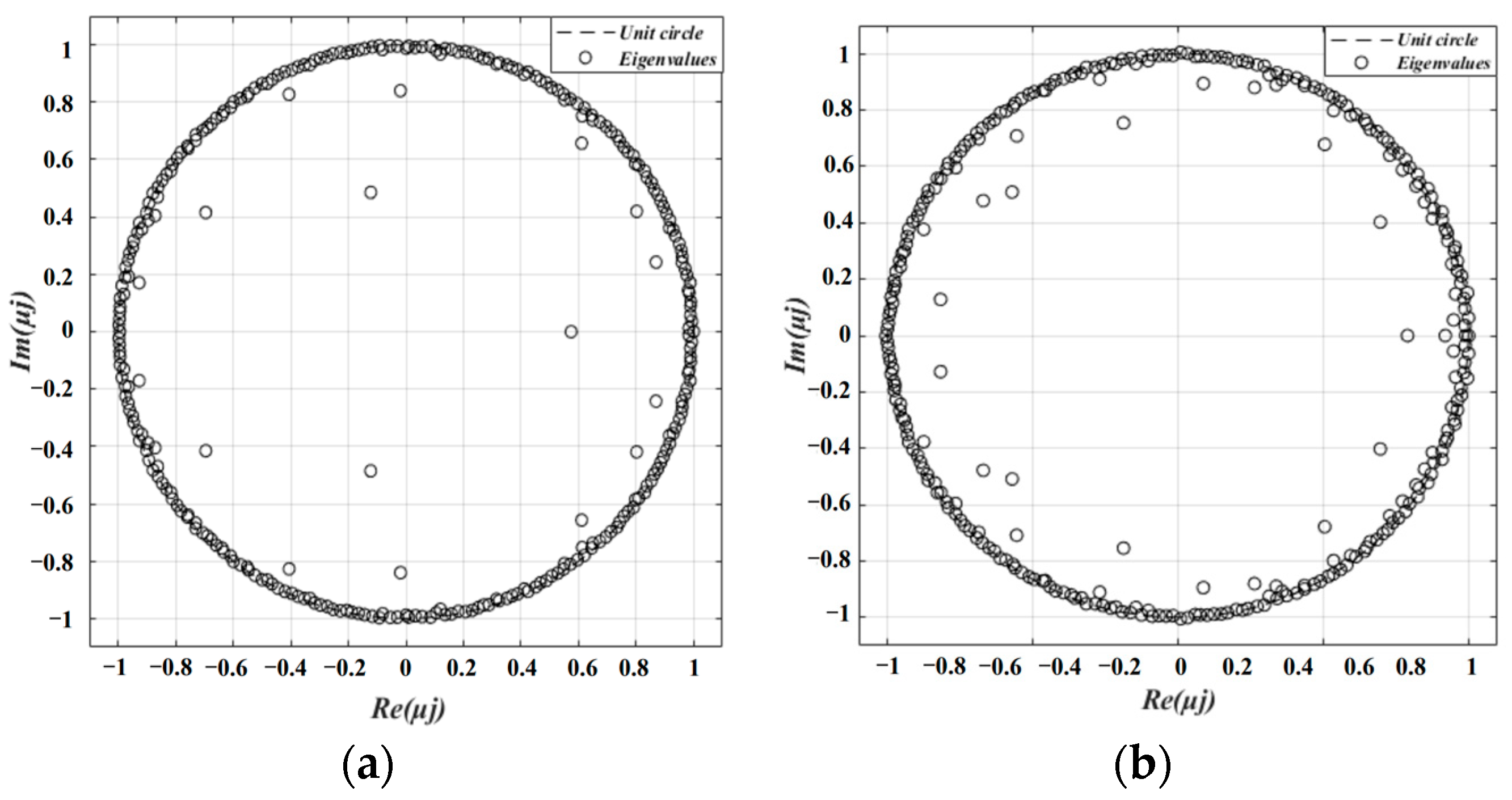
The mode corresponding to the eigenvalue falling in the unit circle is stable; the mode corresponding to the eigenvalue falling outside the unit circle is unstable [63]. The DMD code in this paper is derived from Kutz’s reference [64], which describes in detail the DMD code that implements the above steps.

2.5. Computational Domain and Boundary Conditions

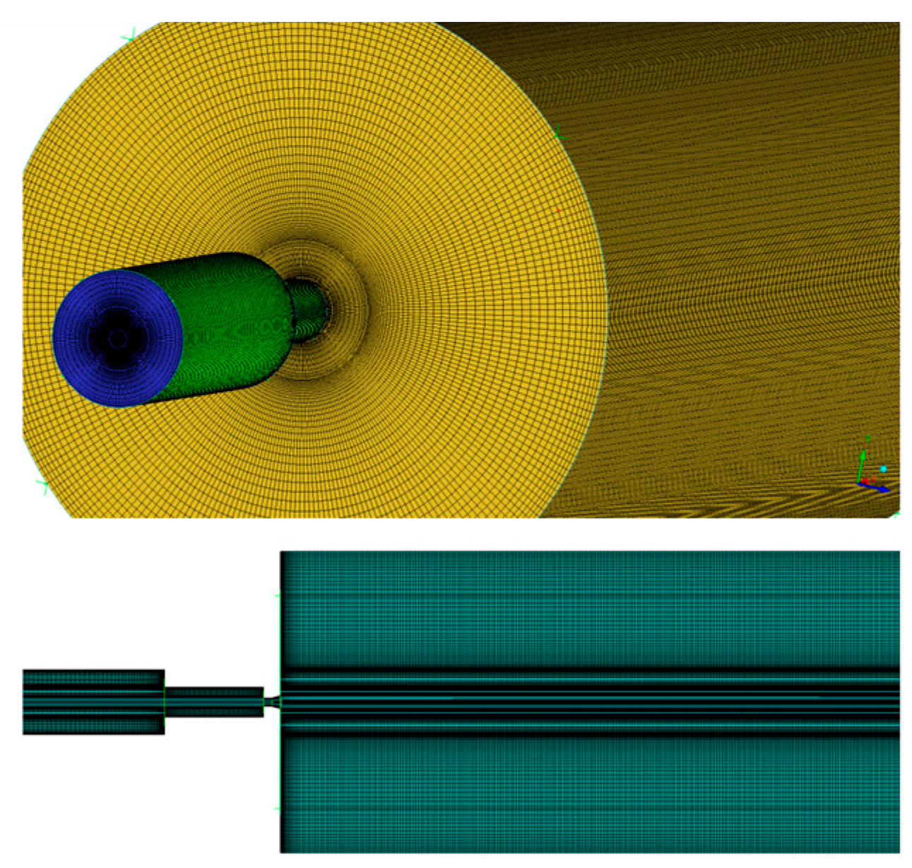
The computational domain examined in this study is shown in Figure 1, with the first half of the computational domain being an oscillating cavity and the second half being a free basin. When a jet moves downstream, vortex disturbances within a range of frequencies are amplified. A series of discrete vortex rings are formed in the shear layer, and when they reach and interact with the collision wall, a pressure oscillation wave is generated in the collision zone, which propagates upstream at the speed of sound and induces a new vortex pulsation. If the pressure pulsations in the separation and collision zones are in anti-phase with each other, a cyclic process of vortex-perturbation–amplification–new-vortex-pulsation-generation is formed. The process is repeated over and over again and a strong self-excited oscillating pulsed jet is formed. Meanwhile, the inlet section model must be lengthened appropriately, to ensure that the jet can fully develop and stabilize before entering the cavity. Local grid refinement was used for computational accuracy, as shown in Figure 2.
In order to better understand the principle of increasing jet pressure amplitude, Tang et al. [65] found that the peak value of a self-excited oscillation pulsed water jet (SEOP jet) is larger by about 20% than that of a continuous jet. The oscillation frequency increased while increasing pump pressure and decreased while increasing cavity length. There was an optimum cavity length corresponding to the pressure peak value of the SEOP jet. Based on the literature of D. Li et al. [66], a range of structural parameters are covered in the simulation, as shown in Table 1.
The boundary conditions in the simulation are as follows: The pressure inlet and the pressure outlet are respectively arranged. The nozzle inlet pressure is set as Pinlet = 15.0 MPa, 20.0 MPa, 25.0 MPa, and 30.0 MPa. The slip velocity of phases and walls is set to 0. The entrance adopted a uniform flow profile and the turbulence intensity is approximately 5%. The Fluent setup uses hybrid initialization. The constant time step of 1 × 10 4 s is used during the simulation. In total, 20 iterations are within each time step; all residuals are below 10−5. Convergence is considered to have occurred when the values at the exit monitoring point oscillate steadily. The pressure-based COUPLED algorithm was used for pressure–velocity coupling.
The enhanced-wall function method was employed to solve the problem of near-wall flow. The vapor volume was observed to analyze the cavitation phenomenon in the fluid-free development zone. Meanwhile, the subgrid scales were determined according to the Smargorinsky model.
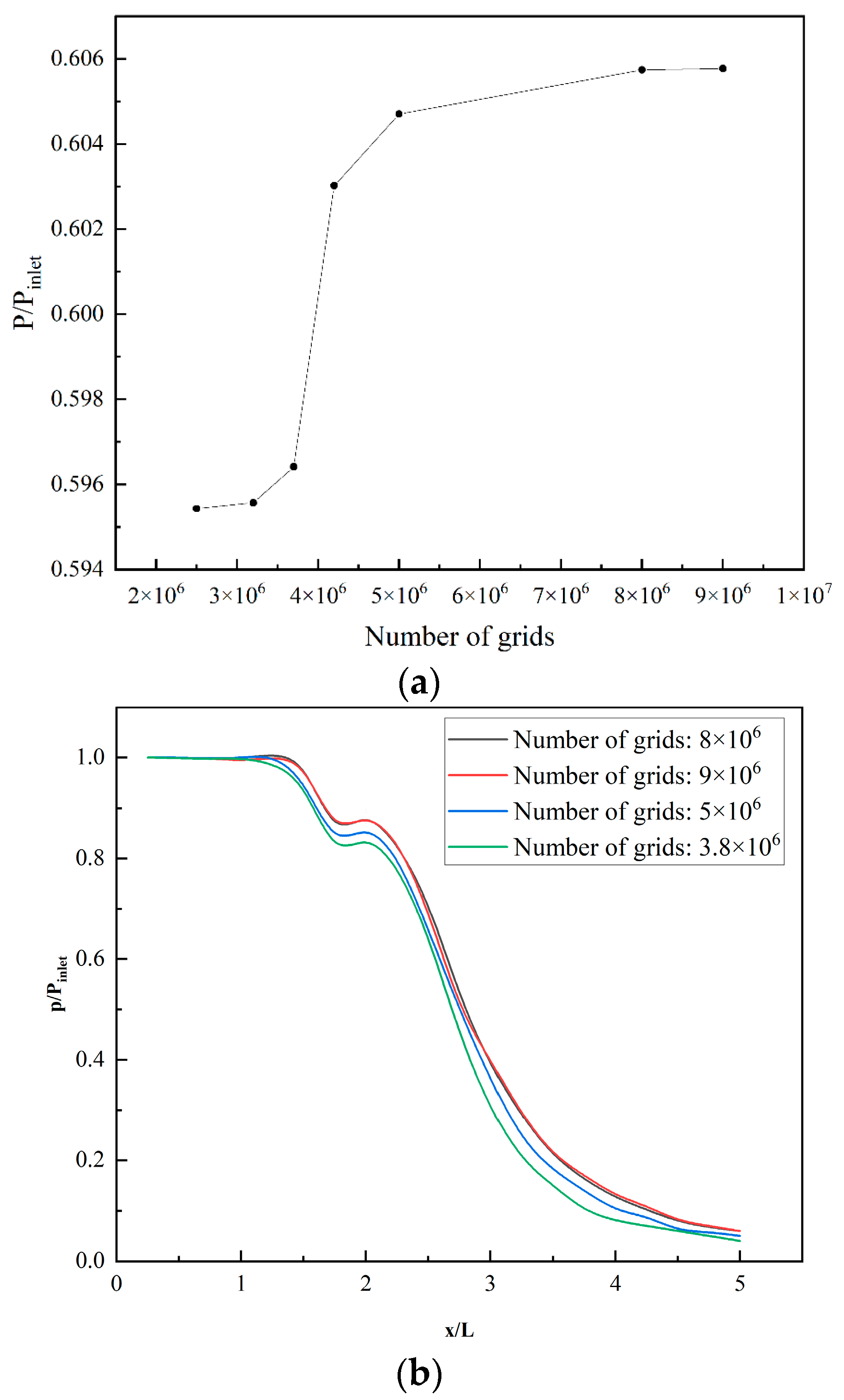
Mesh refinement was used in the area near the wall and inside the nozzle. The minimum grid size was set to 10−5 m, which can meet the requirement that the value of y+ was approximately equal to 1.0. Grid independence was verified by selecting the working condition at Pinlet = 30.0 MPa. The average pressure at x/L = 2.8 and the axial pressure along the axis were selected as the comparison criteria. The computational results of multiple grid numbers were compared, and the results are shown in Figure 3.
It is found that for grid numbers larger than 8 million, the magnitude of the calculated results is stable. This shows that the calculated results are independent of mesh density. The following simulations are all based on a grid number of 8 million.

2.6. Model Validation

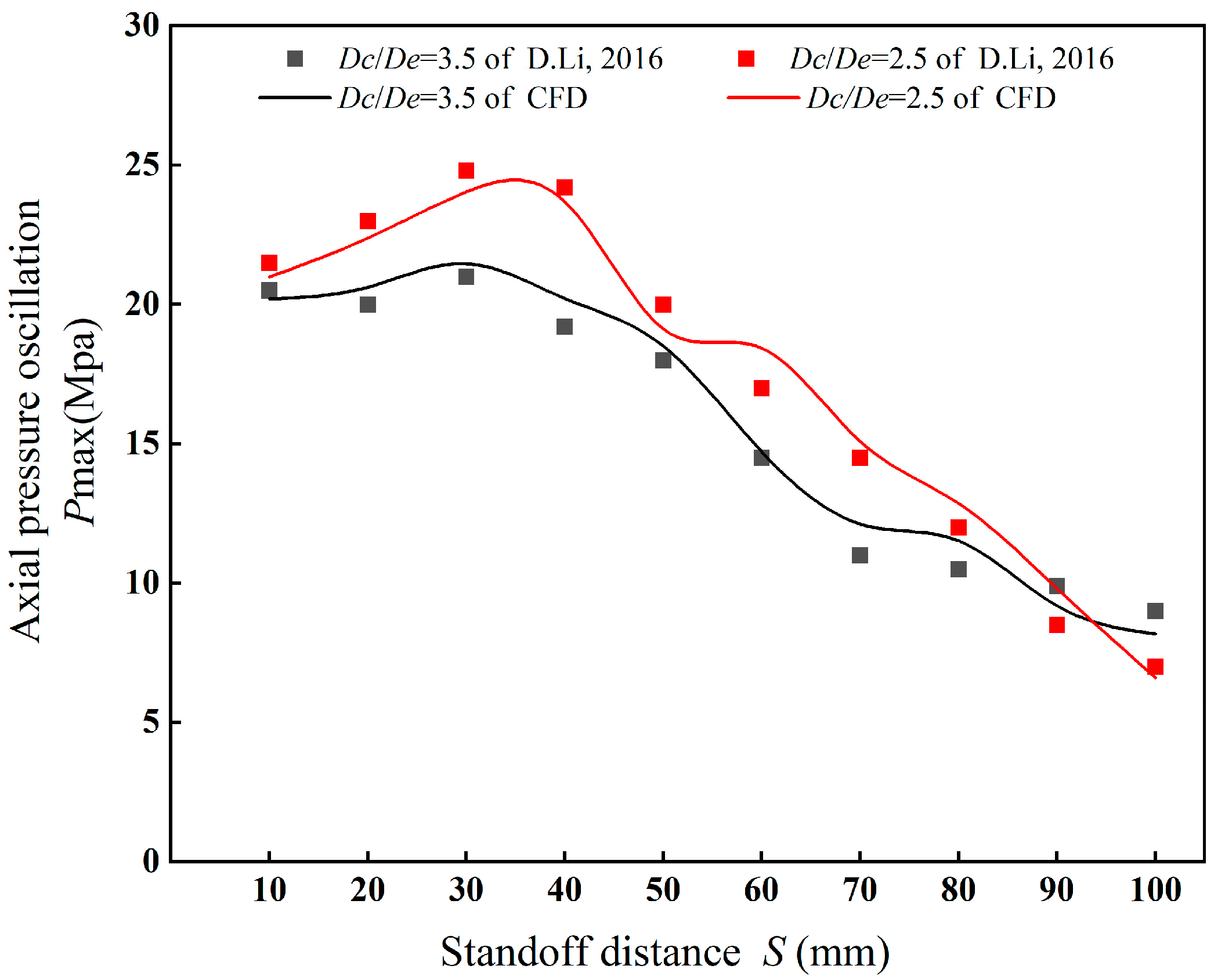
For model validation, the numerical results are compared with reported test data from D. Li et al. [66]. The study reported experimental data on the effect of nozzle cavity shrinkage on axial pressure. The nozzle structure parameters involved in D. Li’s experiment are shown in Table 2. The results were contrasted with the test data for a cavity shrinkage of 2.5 and 3.5.
As shown in Figure 4, the simulation results show that there is an acceptable deviation of 8.9% from the experimental data in terms of the axial pressure of the organ-pipe nozzle under the same condition (Dc/De = 3.5). When the organ-pipe nozzle parameter is Dc/De = 2.5, the deviation between simulation and experimental data reaches 7.5%. Generally, the simulation results are consistent with the experimental data.

3. Results

3.1. Outflow Field Characteristics

3.1.1. Pressure Distribution

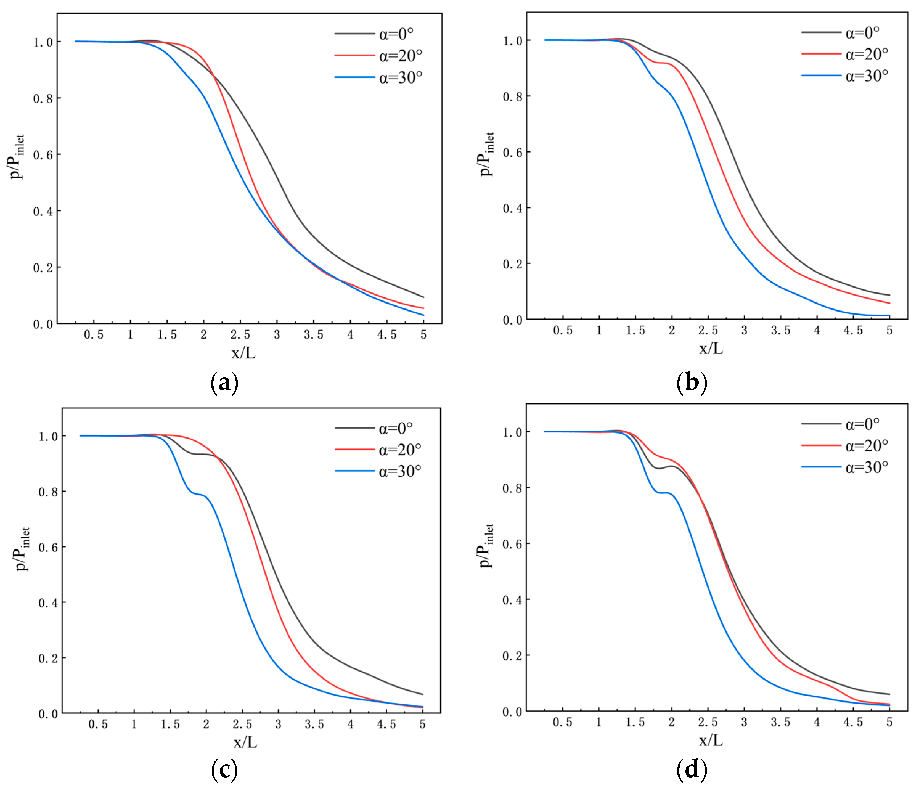
The axial pressure of the nozzle under inlet pressures of Pinlet = 15 MPa, 20 MPa, 25 MPa, and 30 MPa and the outlet expansion angles of α = 0°, 20°, and 30° was drawn as a function of the distance in Figure 5a–d.
Figure 5 shows little effect of the inlet pressure on the jet pressure variation tendency. In the range from 0 to 1.5 x / L , the fluid was inside the nozzle, and the pressure remained almost unchanged. When x / L exceeds 1.5, the fluid leaves the nozzle and the pressure drops rapidly. It is apparent that when x / L is between 1.5 and 2.0, the pressure drop has a slowing process. With the increase in axial distance, in the initial decay section of the jet pressure cliff-like drop, the larger the nozzle divergence angle, the more rapid the pressure drop. Subsequent brief stabilization exists at high-pressure conditions. This is because the velocity in this area decreases from the maximum value, resulting in the conversion of kinetic energy into pressure energy. The pressure drop rate slows down when in the range of 3.5 to 5.0. Under these four inlet pressures, the pressure of the jet produced using the nozzle with a divergence angle of 30° is the smallest, whereas the pressure for a divergence angle of 20° and 0° is the largest. This is because the divergence angle is relevant to the nozzle outlet cross-sectional area, which leads to the pressure drop.

3.1.2. Frequency Characteristics

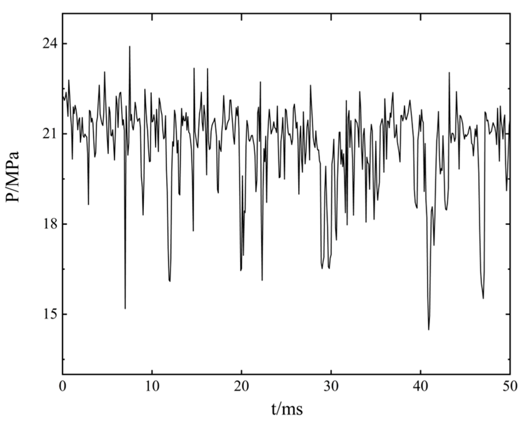
To study the pulsation characteristics of the jet pressure, a monitoring point at the nozzle outlet was selected to detect the pressure pulsation in a period. The conditions are Pinlet = 20 MPa, L c / D e = 11.5 , D c / D e = 3.5 , and α = 30 ° . Figure 6 shows the peak and amplitude of the pressure oscillation. The oscillating outlet pressure induces cavitation and effectively increases the erosive strength of the jet produced using the organ-pipe nozzle.
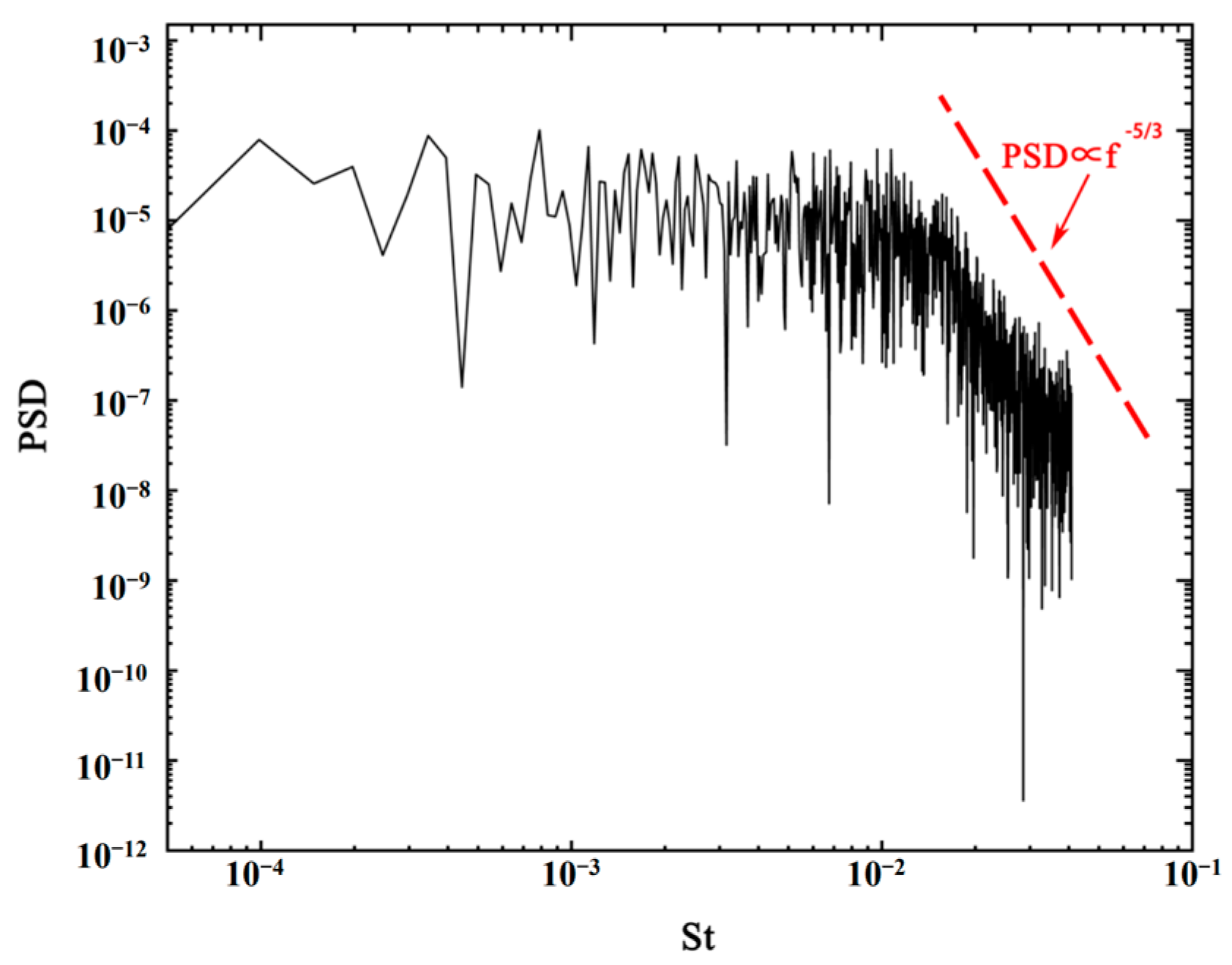
The power spectrum density of nozzle outlet pressure is shown in Figure 7. A total of 1630 discrete data values are at 1 × 10⁻⁴ s intervals. It shows that the −5/3 power law of the pressure spectrum can be calculated in the medium mesh.
The Strouhal number was a similar dimensionless number representing the periodicity of flow. The frequency of the spectrum presented in this paper can be expressed with the Strouhal number after dimensionless processing. The formula for the Strouhal number is as follows
S r = l f v
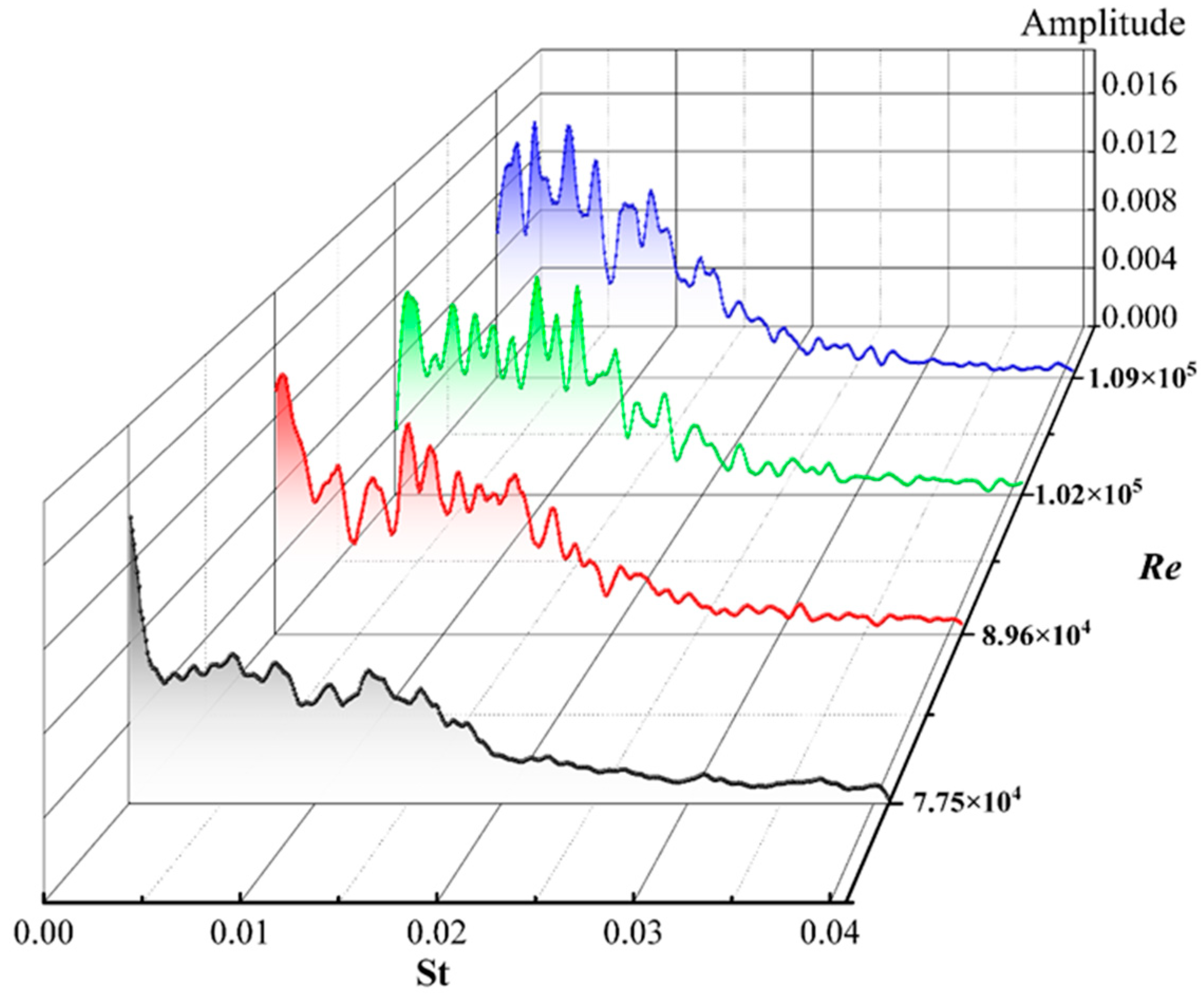
For nozzles with consistent structural dimensions ( L c / D e = 11.5 , D c / D e = 3.5 , and α = 30 ° ), the fluid flow frequency has different characteristics for the pressures range Pinlet = 15 MPa, 20 MPa, 25 MPa, and 30 MPa. The change in inlet pressure corresponds to the change in Reynolds numbers. Figure 8 shows the trend of the frequency characteristics of the mass flow rate as a function of inlet pressure. The curve has multiple peaks in the spectrum, and the peak is the highest at a low frequency and tends to be flat at higher frequencies. The amplitude decreases with the increase in frequency. For a high inlet pressure, the St number increases, meaning that the main fluid frequency shifts to a higher frequency.
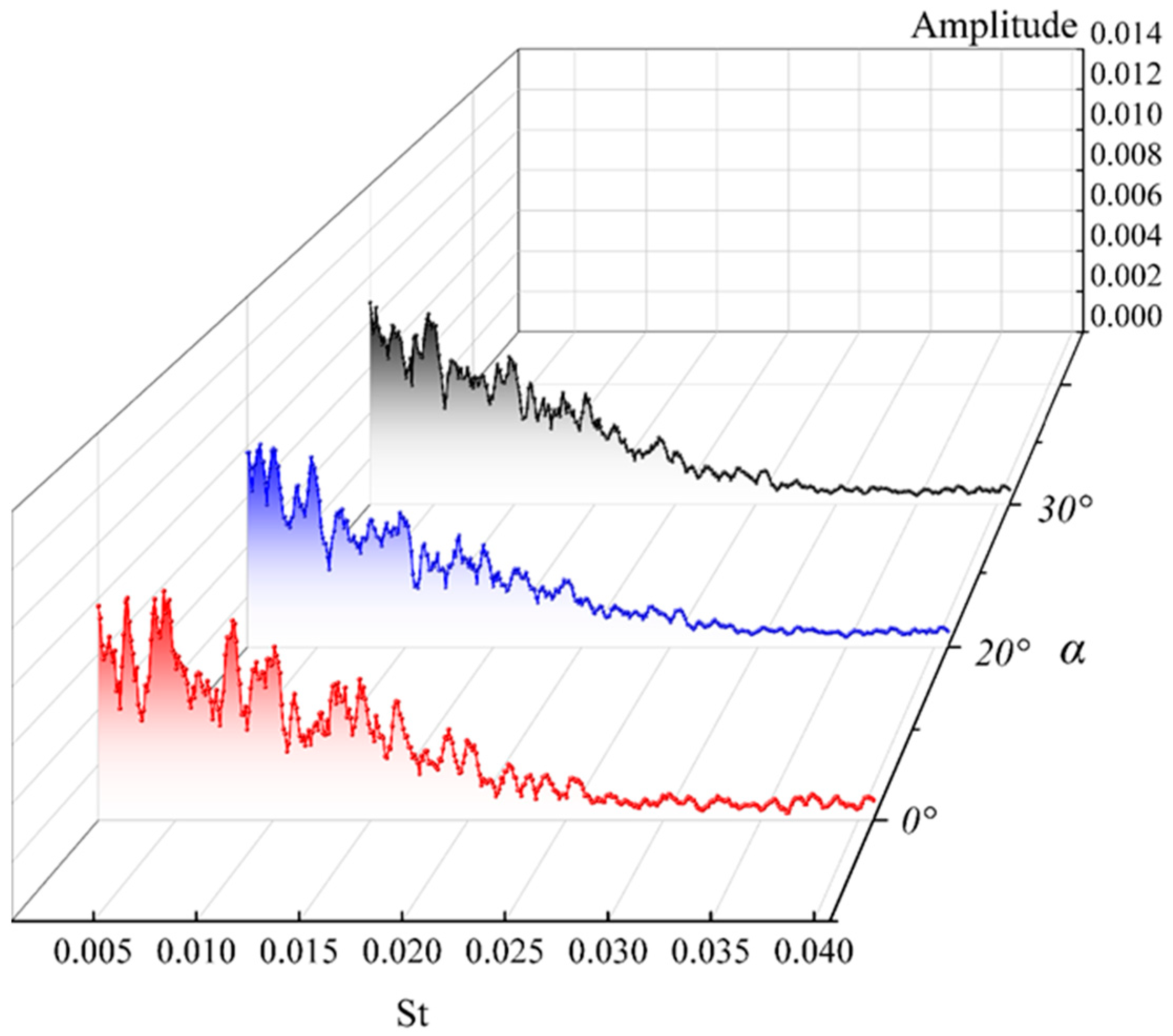
The frequency characteristics of the exit mass flow rate under different outlet divergence angles are shown in Figure 9. L c / D e = 11.5 , D c / D e = 3.5 and α = 0 ° , 20 ° , and 30 ° . The change of outlet divergence angle affects radial development. However, the pulsation frequency is mainly determined with the shedding frequency of the upstream vortex. The influence of the divergence angle is minor compared to that of the inlet pressure.

3.2. Vortex Structure and Cavitation Characteristics

3.2.1. Coherent Structure of the Outflow Field

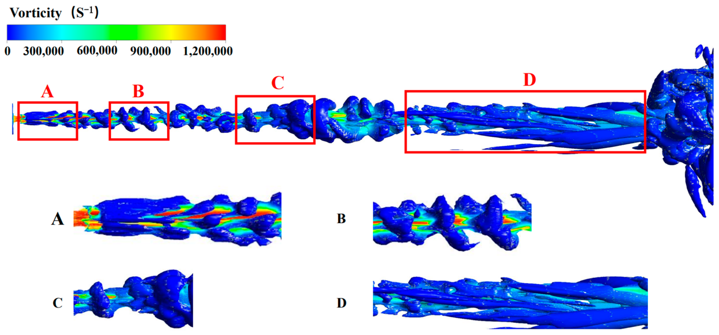
The Q-criterion number is another parameter for investigating the flow characteristics of flow fields. It is used to effectively capture the induced vortex flow at the tip of a leaf (by Bing J. et al. [67]). Here, it was selected as the evaluation basis to analyze the specific process of vortex development, as shown in Figure 10. The vortex of the jet flow field was mainly distributed near the jet shear layer and the nozzle outlet. The eddy current in the outflow field could be divided into four stages.
In stage one (as shown in Section A), as the jet just leaves the nozzle, the velocity is the largest, and the surface of the vortex ring is smooth and extends downstream. In this stage, the vortex is characterized by velocity and stable vortex structure. In the second stage (as shown in Section B), the fluid has been developed for a certain distance. It presents a spiral shape. The volume of the main vortex ring starts to expand and is cut off from several directions. Some small vortex structures are generated around the vortex ring, and the fluid energy is consumed to a certain extent. The characteristic of the vortex in this stage is that the distance between the front and rear vortex rings remains almost unchanged, but the vortex ring starts to break. In the third stage (as shown in Section C), the spiral vortex continues to develop downstream, the main flow velocity of the fluid gradually weakens, the spacing between the two adjacent vortex rings begins to increase, and the patch vortex structure around the vortex begins to separate from the main vortex ring. Due to the cavitation phenomenon at this stage, the bubbles gradually become larger, and the relationship between the main vortex ring and the bubbles becomes irregular. The characteristics are mainly reflected in the change of the vortex ring from regular to irregular, which is the phenomenon of fluid changing into turbulence. In the fourth stage (as shown in Section D), the flow velocity in the center of the fluid is reduced to be almost the same as that in the periphery, and the vortex is completely transformed from a ring-like to a filament-like vortex structure. The vortex here indicates that the jet fluid completely enters the turbulent state.

3.2.2. Cavitation Characteristic and Vortex Structure at Different Divergence Angles

In Figure 11, it is observed that different divergence angles also affected cavitation initiation. As the divergence angle increases, the volume of the primed cavitation bubble increases. The effect of cavitation was more evident: as the cavitation bubble moved downstream, the fluid perturbation of the cavitation bubble amplified this difference, and the cavitation bubble expanded to its maximum. It has been found that the larger the exit divergence angle, the larger the intact cavitation bubble volume is, with a higher cavitation volume. Cavitation bubbles at α = 0°, 20°, and 30° were a fusiform, water droplet, and spherical shape, respectively. As the cavitation bubble moves downstream of the outflow field, the cavitation bubbles generated at three different divergence angles all collapse. But as the divergence angle is increased, the collapse of the cavitation bubble occurs later and the period of cavitation is lengthened, so that the vapor cloud can grow more completely and increase the cavitation intensity.
With comparing the flow fields from the three divergence angle nozzles, the cycle time of the vapor cloud of the jet fluid increased as the divergence angle of the nozzle widened. In addition, the cavitation intensity and vapor volume would scale with a widening divergence angle.
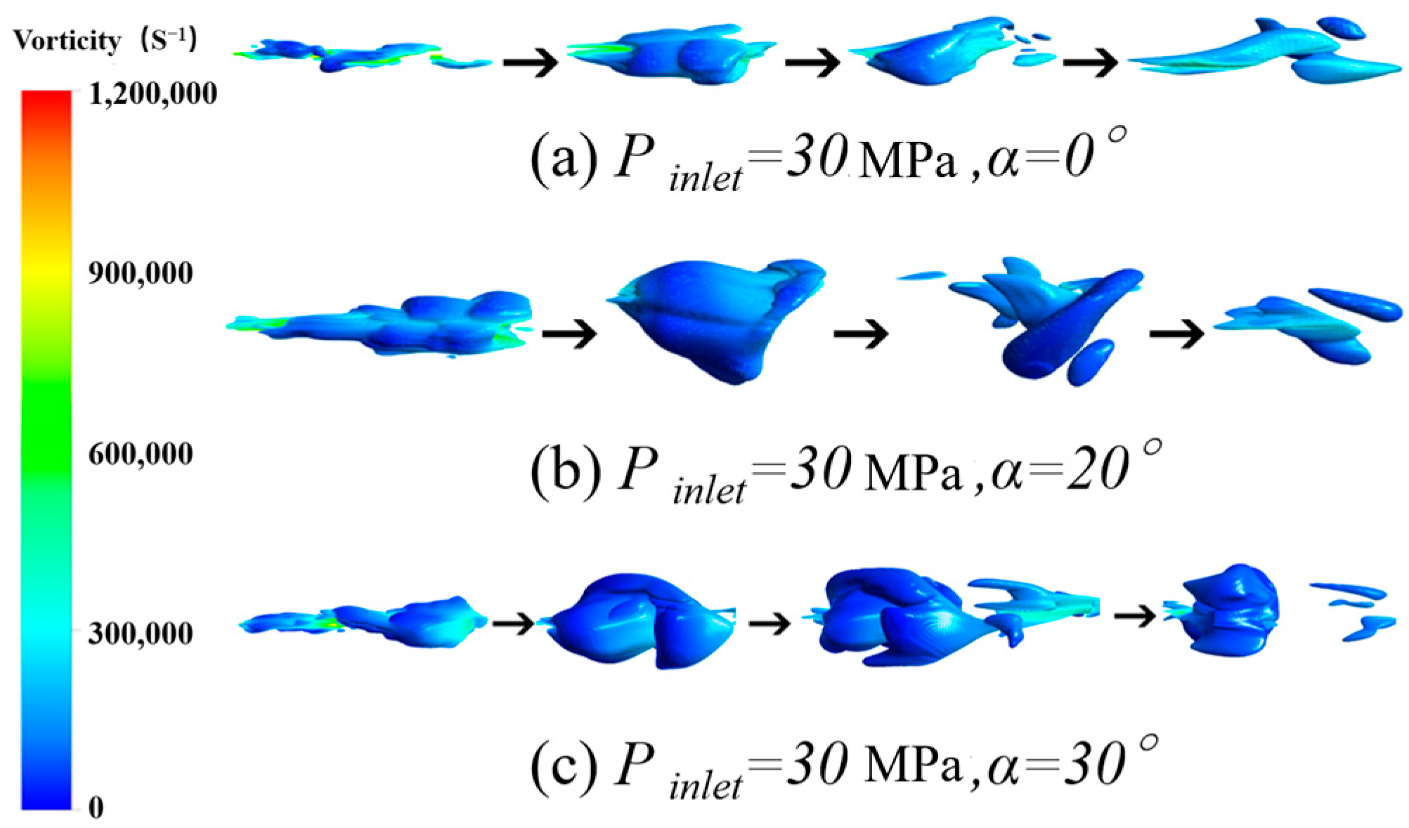
Through the vortex analysis of the external flow field of the jet, it can be clear that the vortex structure near the nozzle outlet changes significantly. To better show the evolutionary process of the shear vortex ring in the jet flow field, the Y-Z plane at different axial distances with three divergence angles was intercepted to observe the changes of the vortex ring on the section.
The instantaneous streamwise vorticity in the vertical planes for the jet is shown in Figure 12a–d at four downstream locations (x/L = 1.50, 1.75, 2.00, and 2.25). The shear vortex ring showed good symmetry, and the vortex ring radius was approximately equal to the nozzle radius, as shown in Figure 12a. With the increase in vortex ring thickness, some patch-shaped vortex structures were developed in the circumferential direction, and some patch structures were separated from the main vortex ring, as shown in Figure 12b. Owing to the impact of the axial secondary vortex structure, the vortex ring starts to disintegrate, as shown in Figure 12c. The intensity of the vortex weakened and the structure dissipated gradually, as shown in Figure 12d.
The variation of vorticity with the distance from the nozzle outlet is shown in Figure 13a–d for P inlet = 30   MPa , α = 20 ° . The radius of the vortex ring was equal to the nozzle radius, and some patch-shaped vortex structures were developed in the circumferential direction, as shown in Figure 13a. The main vortex ring was cut off in two directions and the vortex ring began to disintegrate. The main vortex ring continues to disintegrate, and the vorticity of the local vortex increases, as shown in Figure 13b,c. It was obvious that the vorticity was enhanced with x/L = 1.75 due to the larger diffusion angle. Finally, Figure 13d indicates that the jet developed into a turbulent flow.
The variation of vorticity with the distance from the nozzle outlet is shown in Figure 14a–d for P inlet = 30   MPa , α = 30 ° . The vortex ring radius was slightly larger than the nozzle radius, and the main vortex ring broke. Then, the main vortex ring was cut off in four directions, the vortex ring began to disintegrate, and the vorticity of the vortex structure at the fracture increased, as shown in Figure 14a,b. During the further development of the jet at the downstream, the vortex ring structure was completely broken, and the jet flow field developed into a fully developed turbulent field, as shown in Figure 14c,d. For the jet with α = 30 ° , the highest vorticity was observed on the outlet plane of the nozzle. In addition, the vortex structure was amplified, indicating that a large-scale structure was formed in the nozzle.

3.3. DMD-Based Flow Characteristics’ Analysis of External Flow Fields

The analysis of the flow field pressure characteristics and frequency revealed that the divergence angle of the nozzle has a significant effect on the jet oscillation. To further explore the effect of the divergence angle of the nozzle on the coherent jet structure, the DMD method was used to extract the leading modes of the jet at the beginning and explore the flow characteristics of the jet flow during the cavitation period.
The dynamic mode decomposition was used to analyze the velocity and vortex data from numerical simulations and to investigate the spatial and temporal characteristics of the large-scale coherent structure of the jet with different nozzle configurations. The dynamic mode decomposition of the data was for the operating conditions Pinlet = 15 MPa and the selected nozzle divergence angle α = 0° and 20°. The time for sampling snapshots is 1 × 10⁻⁴ s; 300 snapshots in total were used for the dynamic mode decomposition. In this section, the DMD analysis is carried out for x-direction velocity V and vorticity ω.

3.3.1. Vorticity and Velocity Field Modal Analysis of the External Flow Field

Figure 15 shows the distribution of eigenvalues from the dynamical mode decomposition of the vorticity data, where the horizontal axis is the real part of the modal eigenvalues and the vertical axis corresponds to the imaginary part of the modal eigenvalues. Most of the eigenvalues fall on and inside the unit circle. The mode corresponding to the eigenvalues falling in the unit circle is stable; the mode corresponding to the eigenvalues falling outside the unit circle is unstable [63].
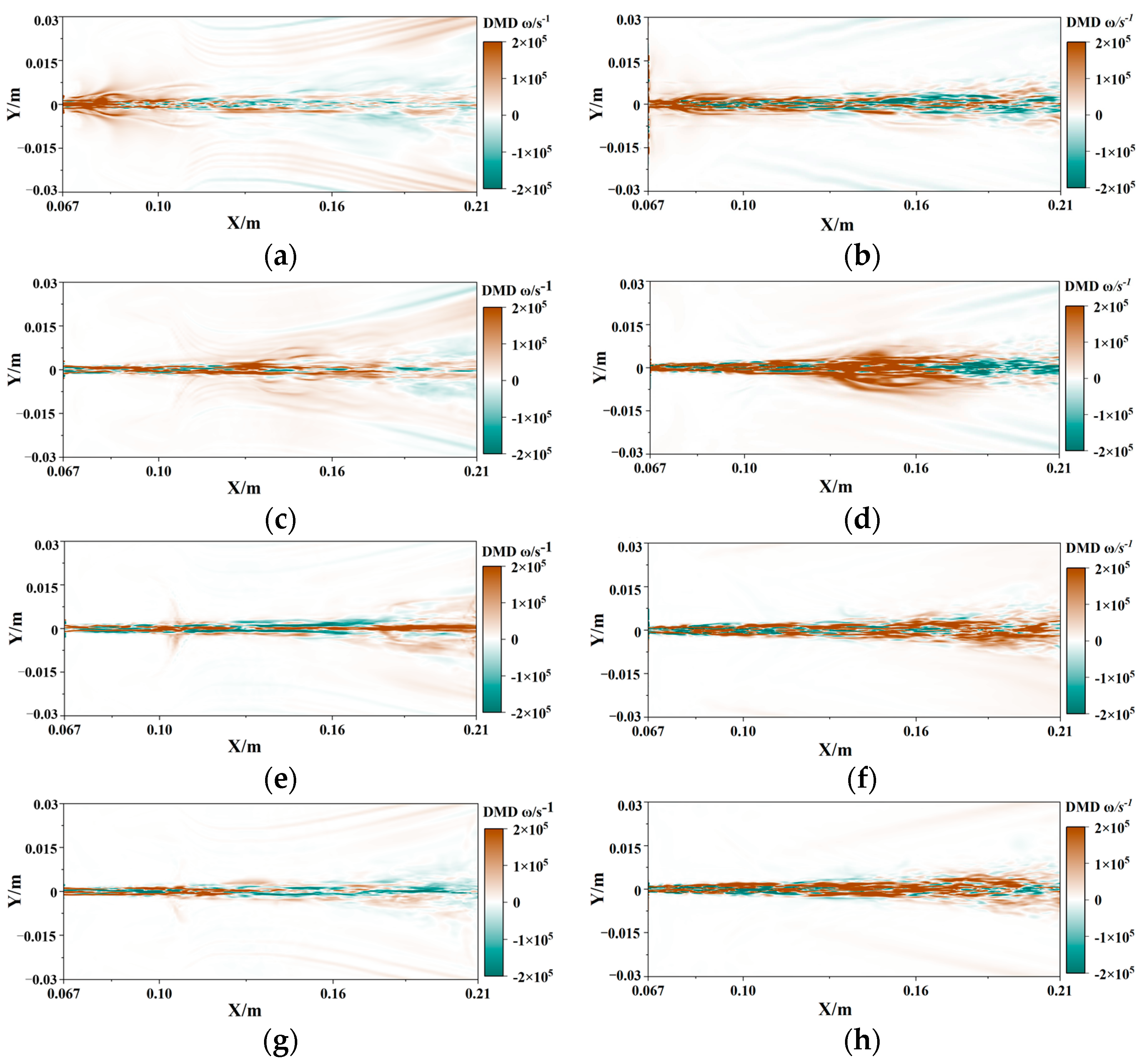
In the left of Figure 16, we show the spatial morphology distribution of the fourth-order DMD mode in front of the z = 0 section of the outflow field at Pinlet = 15 MPa and α = 20°. The four modes are typically each characterized by the multiscale motion of the jet flow field. The structure of the modal flow field contains information about the time-averaged flow field and exhibits the dominant flow structure in the jet flow field.
As shown in Figure 16 (mode 1), the spatial distribution of the first-order modal flow field exhibits a periodic structure of the oscillatory flow, corresponding to the initial phase of self-excited oscillatory jet motion into the outflow field. Table 3 shows that the real part of mode 2 is also negative and static. Compared with mode 1, mode 2 appears as a large-scale continuous eddy structure in the context of the large-scale motion of the flow field, and positive vortices dominate. It should be noted that the rotation direction of the vortex in the mode does not represent the rotation direction of the real vortex in the flow field. The structure of the flow field obtained using the DMD method is unintuitive. Mode 3 has a negative growth rate and is still a static mode. We find that the initial oscillating vortex structure develops into an elliptical shape as it flows downstream, leading to a high vorticity concentration region in the downstream. With increasing frequency, mode 4 shows a significant decrease in the scale of the vortex structure and a stabilization of the corresponding spatial mode.
Table 3 and Table 4 have the same frequency trend. These high frequency modes represent the typical structure embedding to the vortex structure in the dynamical process. The striped coherent structure dominates in the high-speed jet flow field, which portrays the change from generating oscillatory jets to stabilizing in the flow field by comparing the left- and right-column flow modal analysis.
Compared with the divergence angle of 20°, the oscillatory behavior was found to be significantly weakened in the case of a 0° divergence angle and the jet exhibits a better clustering of fluid features.

3.3.2. Vorticity Modal Decomposition and Volume Fraction Cloud Comparison at x = 0.125 m Cross-Section (Pinlet = 15 MPa, α = 20°)

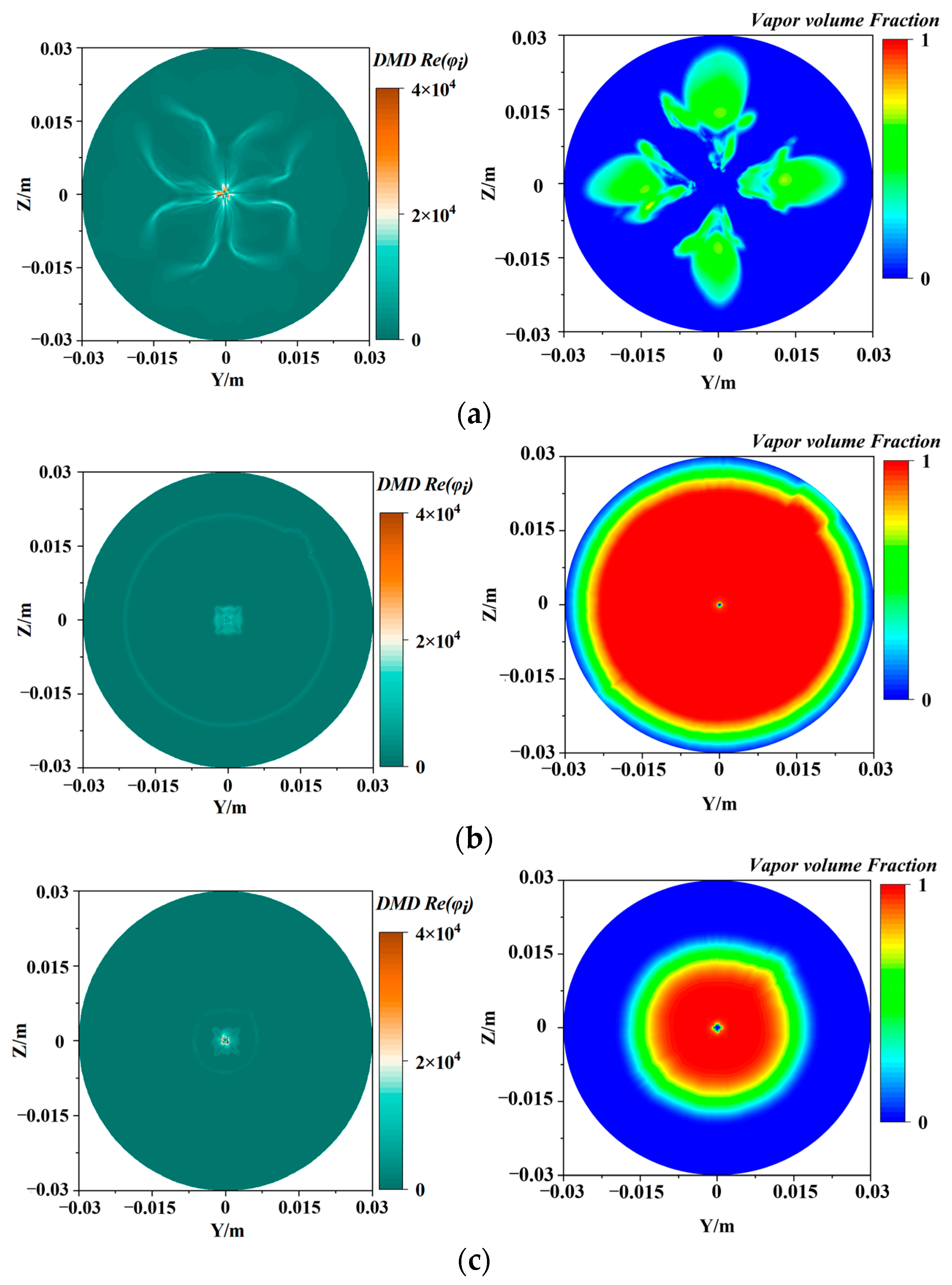
As shown in Figure 17, the dynamic mode decomposition for the vorticity of the x = 0.125 m cross-section is plotted on the left, and the cavitation volume fraction cloud at the corresponding moment is plotted on the right. The vapor volume fraction is weak in the center region and cavitation initially occurs at the shear layer location, corresponding to a value of 0 in the center of the volume fraction plot in mode 1. At this time, the vortex structure in the center of the flow field is compact, and the cavitation cloud spreads along the vortex structure to the outer flow field, indicating that the large-scale vortex structure has a guiding effect on the diffusion of the cavitation cloud in the flow field at the early stage of cavitation. In mode 2, the real part of the modes is concentrated in the outer contour of the volume fraction, indicating that the cavitation cloud motion is wrapped with the large-scale structure moving to the downstream flow field. In mode 3, the vortex structure embedded energy weakens along with the vapor volume fraction as the cavitation cloud leaves the section. Cavitation clouds are always guided by large-scale vortex structures during diffusion in the outflow field.

4. Conclusions

In this study, the 3D turbulent cavitation flow outside an organ-pipe nozzle was numerically studied using LES. The vapor cloud formed outside the organ-pipe nozzle with different divergence angles was observed, and the details of vortex development under corresponding conditions were further analyzed. Combining simulation research of a cavitation jet with the DMD method, the interaction between coherent structure and cavitation was considered from a data-driven perspective. The main results are as follows:
(1) At the nozzle outlet, the downward trend of jet axial pressure will decrease sharply with the raising of inlet pressure. The position of the pressure boundary layer of the fluid is about Y / D e = 0.5 . The increase in the divergence angle will lead to more energy loss of the fluid, and the energy loss of the jet enhances with the extension of outlet distance, and the amplitude of pressure fluctuation will also increase. The change in inlet pressure will affect the change in fluid dominant frequency. The divergence angle does not affect the fluid frequency.
(2) The structural parameters of the organ-pipe nozzle outlet have an important influence on fluid cavitation. With the enlarging of the nozzle divergence angle, the volume of the initial cavitation cloud increases and the cavitation cycle becomes longer, so that the vapor cloud can grow more completely and increase the cavitation intensity. In the research of this paper, the best cavitation intensity was achieved when the divergence angle of the organ-pipe nozzle was 30°.
(3) While the real part of the eigenvalue reflects the growth and decay of the energy/intensity of the flow field at the temporal level, the imaginary part of the eigenvalue reflects the change in the structure of the time-scale flow field, and the stability of the flow field development mode can be judged with the eigenvalue analysis.
(4) Comparing the DMD analysis with the cavitation cloud, it was found that the motion of the cavitation cloud in the flow field is guided by the coherent structure. Large-scale coherent structures appear with cavitation priming and disappear as the cavitation cloud leaves the cross-section.

Author Contributions

Conceptualization, Z.F.; methodology, Y.C.; software, W.H.; validation, Y.Y.; formal analysis, Y.C.; investigation, Z.X.; data curation, W.H.; writing—original draft preparation, W.H.; writing—review and editing, X.G.; visualization, Z.Z.; supervision, R.S.; project administration, Z.Z. All authors have read and agreed to the published version of the manuscript.

Funding

This research was funded by the Finance Science and Technology Project of Hainan Province (grant number: ZDKJ202015), National Natural Science Foundation of China (grant number: 51706161), and Sanya Science and Education Innovation Park of Wuhan University of Technology (grant number: 2021KF0023). This work was also supported by the Green Intelligent Inland Ship Innovation Program.

Institutional Review Board Statement

Not applicable.

Informed Consent Statement

Not applicable.

Data Availability Statement

The data supporting the research findings of this study are available from the corresponding author on request.

Conflicts of Interest

The authors declare no conflict of interest. The funders had no role in the design of the study; in the collection, analyses, or interpretation of data; in the writing of the manuscript; or in the decision to publish the results.

Abbreviations

τ ¯ i j subgrid stress
Sijrate of the strain tensor
Rbbubble radius
Nbbubble number density
Pinletinlet pressure
u ¯ average velocity
Pmedium pressure
vkinematic viscosity
Δ t time step
P B ( t ) pressure inside the bubble
P ( t ) pressure leaving the bubble at infinity
ρ L density of the surrounding liquid
R b bubble radius
S r Strouhal number
Dfinlet diameter
Dccavity diameter
Deexit diameter
Dfree-fluid diameter
Ldevelopment length
Lccavity length
Leexit length
Lofree-fluid length
αoutlet divergence angle
ωvorticity
Re ( μ j ) eigenvalue

References

  1. Hu, Y.; Kang, Y.; Wang, X.-C.; Li, X.-H.; Long, X.-P.; Zhai, G.-Y.; Huang, M. Mechanism and experimental investigation of ultra high pressure water jet on rubber cutting. Int. J. Precis. Eng. Manuf. 2014, 15, 1973–1978. [Google Scholar] [CrossRef]
  2. Ayed, Y.; Robert, C.; Germain, G.; Ammar, A. Development of a numerical model for the understanding of the chip formation in high-pressure water-jet assisted machining. Finite Elem. Anal. Des. 2016, 108, 1–8. [Google Scholar] [CrossRef]
  3. Xiong, S.; Jia, X.; Wu, S.; Li, F.; Ma, M.; Wang, X. Parameter Optimization and Effect Analysis of Low-Pressure Abrasive Water Jet (LPAWJ) for Paint Removal of Remanufacturing Cleaning. Sustain. Sci. 2021, 13, 2900. [Google Scholar] [CrossRef]
  4. Hsu, C.-Y.; Liang, C.-C.; Teng, T.-L.; Nguyen, A.-T. A numerical study on high-speed water jet impact. Ocean Eng. 2013, 72, 98–106. [Google Scholar] [CrossRef]
  5. Zelenak, M.; Foldyna, J.; Scucka, J.; Hloch, S.; Riha, Z. Visualisation and measurement of high-speed pulsating and continuous water jets. Measurement 2015, 72, 1–8. [Google Scholar] [CrossRef]
  6. Cao, S.; Ge, Z.; Zhang, D.; Zhou, Z.; Lu, Y.; Zhao, H. An experimental study of ultra-high pressure water jet-induced fracture mechanisms and pore size evolution in reservoir rocks. Int. J. Rock Mech. Min. Sci. 2022, 150, 4995. [Google Scholar] [CrossRef]
  7. Qu, H.; Tang, S.M.; Sheng, M.; Liu, Z.H.; Wang, R.; Hu, Y.S. Experimental investigation of the damage characteristics and breaking process of shale by abrasive waterjet impact. J. Pet. Sci. Eng. 2022, 211, 12. [Google Scholar] [CrossRef]
  8. Feng, L.; Dong, X.W.; Li, Z.L.; Liu, G.R.; Sun, Z.C. Modeling of Waterjet Abrasion in Mining Processes Based on the Smoothed Particle Hydrodynamics (SPH) Method. Int. J. Comput. Methods 2020, 17, 29. [Google Scholar] [CrossRef]
  9. Chen, Y.; Fang, Z.; Xiong, T.; Hou, W.; Zhang, Z.; Shi, R. An experimental study on the erosion of sandstone by self-excited oscillation cavitation waterjet in submerged environment. Ocean Eng. 2023, 279, 4546. [Google Scholar] [CrossRef]
  10. Dehkhoda, S.; Hood, M.; Alehossein, H.; Buttsworth, D. Analytical and Experimental Study of Pressure Dynamics in a Pulsed Water Jet Device. Flow Turbul. Combust. 2012, 89, 97–119. [Google Scholar] [CrossRef]
  11. Dehkhoda, S.; Hood, M. An experimental study of surface and sub-surface damage in pulsed water-jet breakage of rocks. Int. J. Rock Mech. Min. Sci. 2013, 63, 138–147. [Google Scholar] [CrossRef]
  12. Dehkhoda, S.; Hood, M. The internal failure of rock samples subjected to pulsed water jet impacts. Int. J. Rock Mech. Min. Sci. 2014, 66, 91–96. [Google Scholar] [CrossRef]
  13. Hu, D.; Li, X.H.; Tang, C.L.; Kang, Y. Analytical and experimental investigations of the pulsed air-water jet. J. Fluids Struct. 2015, 54, 88–102. [Google Scholar] [CrossRef]
  14. Cheng, H.-Y.; Ji, B.; Long, X.-P.; Huai, W.-X.; Farhat, M. A review of cavitation in tip-leakage flow and its control. J. Hydrodyn. 2021, 33, 226–242. [Google Scholar] [CrossRef]
  15. Shi, L.; Zhang, D.; Zhao, R.; Shi, W.; Jin, Y. Effect of blade tip geometry on tip leakage vortex dynamics and cavitation pattern in axial-flow pump. Sci. China Technol. Sci. 2017, 60, 1480–1493. [Google Scholar] [CrossRef]
  16. Pei, J.H. Study on the Relation Between Oscillation Frequency of Self-excited Oscillation Pulsed Water Jet and Self-excited Pulsed Water Jet Devices. In Proceedings of the International Conference on Materials and Products Manufacturing Technology (ICMPMT 2011), Chengdu, China, 28–30 October 2011; pp. 547–552. [Google Scholar]
  17. Liu, W.; Kang, Y.; Zhang, M.; Wang, X.; Li, D.; Xie, L. Experimental and theoretical analysis on chamber pressure of a self-resonating cavitation waterjet. Ocean Eng. 2018, 151, 33–45. [Google Scholar] [CrossRef]
  18. Fang, Z.L.; Gao, X.; Tao, X.; Li, D.; Zhang, M.D.; Xiong, T.; Jiang, P. Impact Performance of Helmholtz Self-Excited Oscillation Waterjets Used for Underground Mining. Appl. Sci. 2019, 9, 3235. [Google Scholar] [CrossRef]
  19. Wang, X.L.; Kang, Y.; Zhang, M.D.; Yuan, M.; Li, D. The Effects of the Downstream Contraction Ratio of Organ-Pipe Nozzle on the Pressure Oscillations of Self-Resonating Waterjets. Energies 2018, 11, 3137. [Google Scholar] [CrossRef]
  20. Li, D.; Kang, Y.; Ding, X.L.; Wang, X.C.; Fang, Z.L. Effects of area discontinuity at nozzle inlet on the characteristics of high speed self-excited oscillation pulsed waterjets. Exp. Therm Fluid Sci. 2016, 79, 254–265. [Google Scholar] [CrossRef]
  21. Li, D.; Kang, Y.; Ding, X.L.; Wang, X.C.; Liu, W.C. Effects of feeding pipe diameter on the performance of a jet-driven Helmholtz oscillator generating pulsed waterjets. J. Mech. Sci. Technol. 2017, 31, 1203–1212. [Google Scholar] [CrossRef]
  22. Shi, H.Q.; Kang, Y.; Li, D.; Fang, Z.L. Effects of the exit aspect ratio of organ-pipe nozzle on the axial pressure oscillation characteristics of self-resonating waterjet. Proc. Inst. Mech. Eng. Part C J. Mech. Eng. Sci. 2020, 234, 4589–4598. [Google Scholar] [CrossRef]
  23. Wang, X.C.; Li, Y.Q.; Hu, Y.; Ding, X.L.; Xiang, M.J.; Li, D. An Experimental Study on the Jet Pressure Performance of Organ-Helmholtz (O-H), Self-Excited Oscillating Nozzles. Energies 2020, 13, 367. [Google Scholar] [CrossRef]
  24. Yuan, M.; Li, D.; Kang, Y.; Shi, H.; Hu, Y. The Characteristics of Self-Resonating Jet Issuing from the Helmholtz Nozzle Combined with a Venturi Tube Structure. J. Appl. Fluid Mech. 2020, 13, 779–791. [Google Scholar] [CrossRef]
  25. Shi, D.Y.; Xing, Y.L.; Wang, L.F.; Chen, Z. Numerical Simulation and Experimental Research of Cavitation Jets in Dual-Chamber Self-Excited Oscillating Pulsed Nozzles. Shock. Vib. 2022, 2022, 8288. [Google Scholar] [CrossRef]
  26. Peng, K.W.; Tian, S.C.; Li, G.S.; Huang, Z.W.; Yang, R.Y.; Guo, Z.Q. Bubble dynamics characteristics and influencing factors on the cavitation collapse intensity for self-resonating cavitating jets. Pet. Explor. Dev. 2018, 45, 343–350. [Google Scholar] [CrossRef]
  27. Soyama, H. High-speed observation of a cavitating jet in air. J. Fluids Eng. Trans. Asme 2005, 127, 1095–1101. [Google Scholar] [CrossRef]
  28. Li, S.; Li, Y.B.; Zhang, A.M. Numerical analysis of the bubble jet impact on a rigid wall. Appl. Ocean Res. 2015, 50, 227–236. [Google Scholar] [CrossRef]
  29. Jeffers, N.; Stafford, J.; Conway, C.; Punch, J.; Walsh, E. The influence of the stagnation zone on the fluid dynamics at the nozzle exit of a confined and submerged impinging jet. Exp. Fluids 2016, 57, 17. [Google Scholar] [CrossRef]
  30. Peng, G.Y.; Oguma, Y.; Shimizu, S. Numerical analysis of cavitation cloud shedding in a submerged water jet. In Proceedings of the 2nd Conference of Global Chinese Scholars on Hydrodynamics (CCSH’ 2016), Wuxi, China, 11–14 November 2016; pp. 263–269. [Google Scholar]
  31. Liu, W.C.; Kang, Y.; Zhang, M.X.; Wang, X.C.; Li, D. Self-sustained oscillation and cavitation characteristics of a jet in a Helmholtz resonator. Int. J. Heat Fluid Flow 2017, 68, 158–172. [Google Scholar] [CrossRef]
  32. Liu, W.C.; Kang, Y.; Zhang, M.X.; Zhou, Y.X.; Wang, X.C.; Li, D. Frequency Modulation and Erosion Performance of a Self-Resonating Jet. Appl. Sci. 2017, 7, 932. [Google Scholar] [CrossRef]
  33. Ge, M.; Petkovšek, M.; Zhang, G.; Jacobs, D.; Coutier-Delgosha, O. Cavitation dynamics and thermodynamic effects at elevated temperatures in a small Venturi channel. Int. J. Heat Mass Transf. 2021, 170, 970. [Google Scholar] [CrossRef]
  34. Ge, M.; Zhang, G.; Petkovšek, M.; Long, K.; Coutier-Delgosha, O. Intensity and regimes changing of hydrodynamic cavitation considering temperature effects. J. Clean. Prod. 2022, 338, 470. [Google Scholar] [CrossRef]
  35. Ge, M.; Sun, C.; Zhang, G.; Coutier-Delgosha, O.; Fan, D. Combined suppression effects on hydrodynamic cavitation performance in Venturi-type reactor for process intensification. Ultrason. Sonochem. 2022, 86, 106035. [Google Scholar] [CrossRef] [PubMed]
  36. Wu, X.-Y.; Zhang, Y.-Q.; Tan, Y.-W.; Li, G.-S.; Peng, K.-W.; Zhang, B. Flow-visualization and numerical investigation on the optimum design of cavitating jet nozzle. Pet. Sci. 2022, 19, 2284–2296. [Google Scholar] [CrossRef]
  37. Ji, B.; Long, Y.; Long, X.P.; Qian, Z.D.; Zhou, J.J. Large eddy simulation of turbulent attached cavitating flow with special emphasis on large scale structures of the hydrofoil wake and turbulence-cavitation interactions. J. Hydrodyn. 2017, 29, 27–39. [Google Scholar] [CrossRef]
  38. Ji, B.; Luo, X.W.; Arndt, R.E.A.; Wu, Y.L. Numerical simulation of three dimensional cavitation shedding dynamics with special emphasis on cavitation-vortex interaction. Ocean Eng. 2014, 87, 64–77. [Google Scholar] [CrossRef]
  39. Cheng, H.Y.; Long, X.P.; Ji, B.; Peng, X.X.; Farhat, M. LES investigation of the influence of cavitation on flow patterns in a confined tip-leakage flow. Ocean Eng. 2019, 186, 106115. [Google Scholar] [CrossRef]
  40. Deng, L.F.; Long, Y.; Ji, B. Delayed detached eddy simulation and vorticity analysis of cavitating flow around a marine propeller behind the hull. Ocean Eng. 2022, 264, 112442. [Google Scholar] [CrossRef]
  41. Wang, Z.; Cheng, H.; Ji, B.; Peng, X. Numerical investigation of inner structure and its formation mechanism of cloud cavitating flow. Int. J. Multiph. Flow 2023, 165, 104484. [Google Scholar] [CrossRef]
  42. Long, X.; Cheng, H.; Ji, B.; Arndt, R.E.A.; Peng, X. Large eddy simulation and Euler–Lagrangian coupling investigation of the transient cavitating turbulent flow around a twisted hydrofoil. Int. J. Multiph. Flow 2018, 100, 41–56. [Google Scholar] [CrossRef]
  43. Wang, Z.Y.; Cheng, H.Y.; Ji, B. Euler-Lagrange study of cavitating turbulent flow around a hydrofoil. Phys. Fluids 2021, 33, 18. [Google Scholar] [CrossRef]
  44. Long, Y.; Long, X.; Ji, B.; Xing, T. Verification and validation of Large Eddy Simulation of attached cavitating flow around a Clark-Y hydrofoil. Int. J. Multiph. Flow 2019, 115, 93–107. [Google Scholar] [CrossRef]
  45. Fang, Z.L.; Zeng, F.D.; Xiong, T.; Wei, W.; Jiang, P.; Wu, Q.; Wang, Y.S.; Fei, Y.X. Large eddy simulation of self-excited oscillation inside Helmholtz oscillator. Int. J. Multiph. Flow 2020, 126, 103253. [Google Scholar] [CrossRef]
  46. Fang, Z.L.; Wu, Q.; Zhang, M.D.; Liu, H.Y.; Jiang, P.; Li, D. Large Eddy Simulation of Self-Excited Oscillation Pulsed Jet (SEOPJ) Induced by a Helmholtz Oscillator in Underground Mining. Energies 2019, 12, 2161. [Google Scholar] [CrossRef]
  47. Fang, Z.L.; Wu, Q.; Jiang, P.; Wei, W. Numerical investigation on flow field characteristics of Helmholtz oscillator. In Proceedings of the 29th IAHR Symposium on Hydraulic Machinery and Systems (IAHR), Kyoto, Japan, 16–21 September 2018. [Google Scholar]
  48. Fang, Z.L.; Kang, Y.; Wang, X.C.; Li, D.; Hu, Y.; Huang, M.; Wang, X.Y. Numerical and experimental investigation on flow field characteristics of organ pipe nozzle. In Proceedings of the 27th IAHR Symposium on Hydraulic Machinery and Systems (IAHR), Montreal, QC, Canada, 22–26 September 2014. [Google Scholar]
  49. Boguslawski, A.; Tyliszczak, A.; Drobniak, S.; Asendrych, D. Self-sustained oscillations in a homogeneous-density round jet. J. Turbul. 2013, 14, 25–52. [Google Scholar] [CrossRef]
  50. Wang, G.; Yang, Y.; Wang, C.; Shi, W.; Li, W.; Pan, B. Effect of Nozzle Outlet Shape on Cavitation Behavior of Submerged High-Pressure Jet. Machines 2021, 10, 4. [Google Scholar] [CrossRef]
  51. Rowley, C.W.; Dawson, S.T.M. Model Reduction for Flow Analysis and Control. In Annual Review of Fluid Mechanics; Davis, S.H., Moin, P., Eds.; Princeton University: Princeton, NJ, USA, 2017; Volume 49, pp. 387–417. [Google Scholar]
  52. Seena, A.; Sung, H.J. Dynamic mode decomposition of turbulent cavity flows for self-sustained oscillations. Int. J. Heat Fluid Flow 2011, 32, 1098–1110. [Google Scholar] [CrossRef]
  53. Mariappan, S.; Gardner, A.D.; Richter, K.; Raffel, M. Analysis of Dynamic Stall Using Dynamic Mode Decomposition Technique. AIAA J. 2014, 52, 2427–2439. [Google Scholar] [CrossRef]
  54. Wan, Z.H.; Zhou, L.; Wang, B.F.; Sun, D.J. Dynamic mode decomposition of forced spatially developed transitional jets. Eur. J. Mech. B 2015, 51, 16–26. [Google Scholar] [CrossRef]
  55. Mohan, A.T.; Gaitonde, D.V. Analysis of Airfoil Stall Control Using Dynamic Mode Decomposition. J. Aircr. 2017, 54, 1508–1520. [Google Scholar] [CrossRef]
  56. Larusson, R.; Andersson, N.; Ostlund, J. Dynamic Mode Decomposition of a Separated Nozzle Flow with Transonic Resonance. AIAA J. 2017, 55, 1295–1306. [Google Scholar] [CrossRef]
  57. Pirozzoli, S.; Bernardini, M.; Marie, S.; Grasso, F. Early evolution of the compressible mixing layer issued from two turbulent streams. J. Fluid Mech. 2015, 777, 196–218. [Google Scholar] [CrossRef]
  58. Yang, L.; Dong, M.; Fu, B.S.; Qiang, L.; Zhang, C.X. Direct numerical simulation of fine flow structures of subsonic-supersonic mixing layer. Aerosp. Sci. Technol. 2019, 95, 105431. [Google Scholar] [CrossRef]
  59. Xu, Y.; Liu, H.; Wang, Z.; Zhang, J.; Wang, J. Analysis of the Effects of Nozzle Geometry on the Cavitation Water Jet Flow Field Using Orthogonal Decomposition. Iran. J. Sci. Technol. Trans. Mech. Eng. 2023. [Google Scholar] [CrossRef]
  60. Liang, W.; Chen, T.; Wang, G.; Huang, B. Investigation of unsteady liquid nitrogen cavitating flows with special emphasis on the vortex structures using mode decomposition methods. Int. J. Heat Mass Transf. 2020, 157, 119880. [Google Scholar] [CrossRef]
  61. Ge, M.; Manikkam, P.; Ghossein, J.; Kumar Subramanian, R.; Coutier-Delgosha, O.; Zhang, G. Dynamic mode decomposition to classify cavitating flow regimes induced by thermodynamic effects. Energy 2022, 254, 124426. [Google Scholar] [CrossRef]
  62. Lilly, D.K. A proposed modification of the Germano subgrid-scale closure method. Phys. Fluids A 1992, 4, 633–635. [Google Scholar] [CrossRef]
  63. Cheng, Y.; Chen, Q. Large Eddy Simulation and Dynamic Mode Decomposition of Turbulent Mixing Layers. Appl. Sci. 2021, 11, 12127. [Google Scholar] [CrossRef]
  64. Kutz, J.N.; Brunton, S.; Brunton, B.W.; Proctor, J.L. Dynamic Mode Decomposition Data-Driven Modeling of Complex Systems; David Marshall: Philadelphia, PA, USA, 2016; pp. 34–37. [Google Scholar]
  65. Tang, C.L.; Hu, D.; Zhang, F.H. Study on the Frequency Characteristic of Self-Excited Oscillation Pulsed Water Jet. Adv. Mater. Res. 2011, 317–319, 1456–1461. [Google Scholar] [CrossRef]
  66. Li, D.; Kang, Y.; Ding, X.; Liu, W. Experimental study on the effects of feeding pipe diameter on the cavitation erosion performance of self-resonating cavitating waterjet. Exp. Therm Fluid Sci. 2017, 82, 314–325. [Google Scholar] [CrossRef]
  67. Cheng, H.; Long, X.; Ji, B.; Peng, X.; Farhat, M. A new Euler-Lagrangian cavitation model for tip-vortex cavitation with the effect of non-condensable gas. Int. J. Multiph. Flow 2021, 134, 103441. [Google Scholar] [CrossRef]
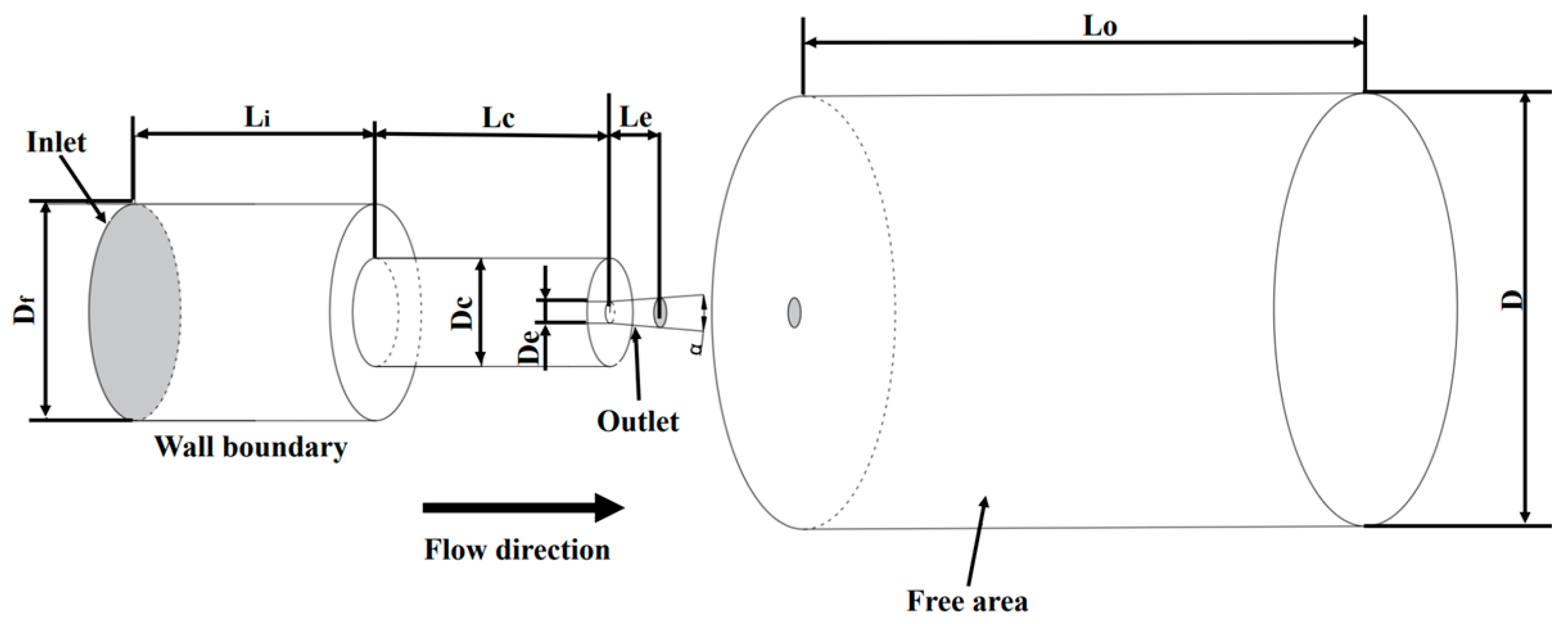
Figure 1. The schematic diagram of the calculation domain.
Processes 11 02460 g001
Figure 2. Three-dimensional model and mesh.
Processes 11 02460 g002
Figure 3. Results of the mesh independence study for Helmholtz oscillator. (a) Average pressure variation at x/L = 2.8 in different numbers of grids. (b) Axial pressure distribution with a different number of grids.
Processes 11 02460 g003
Figure 4. Comparison diagram of simulation and test data [66].
Processes 11 02460 g004
Figure 5. Axial pressure distribution. (a) Pinlet = 15 MPa. (b) Pinlet = 20 MPa. (c) Pinlet = 25 MPa. (d) Pinlet = 30 MPa.
Processes 11 02460 g005
Figure 6. Jet pressure pulsation at the nozzle outlet.
Processes 11 02460 g006
Figure 7. The spectrum of outlet pressure.
Processes 11 02460 g007
Figure 8. Frequency diagram of outlet mass flow with pressure change.
Processes 11 02460 g008
Figure 9. Frequency diagram of outlet mass flow with divergence angle change.
Processes 11 02460 g009
Figure 10. The diagram of the vortex evolution process.
Processes 11 02460 g010
Figure 11. Evolution of a single cavitation bubble at different divergence angles.
Processes 11 02460 g011
Figure 12. Two-dimensional vortex structure ( P inlet = 30   MPa , α = 0 ° ).
Processes 11 02460 g012
Figure 13. Two-dimensional vortex structure ( P inlet = 30   MPa , α = 20 ° ).
Processes 11 02460 g013
Figure 14. Two-dimensional vortex structure ( P inlet = 30   MPa , α = 30 ° ).
Processes 11 02460 g014
Figure 15. DMD analysis of z-direction vorticity ω: modal eigenvalues’ distribution. (a) α = 20°; (b) α = 0°.
Processes 11 02460 g015
Figure 16. DMD analysis of z-direction vorticity ω at P = 15 MPa: first 4 modes. The left column shows the modal decomposition of the vorticity flow field at a divergence angle of 20°; the right column shows the modal decomposition of the vorticity flow field at a divergence angle of 0°. (a) Mode 1 (Pinlet = 15 MPa, α = 20°). (b) Mode 1 (Pinlet = 15 MPa, α = 0°). (c) Mode 2 (Pinlet = 15 MPa, α = 20°). (d) Mode 2 (Pinlet = 15 MPa, α = 0°). (e) Mode 3 (Pinlet = 15 MPa, α = 20°). (f) Mode 3 (Pinlet = 15 MPa, α = 0°). (g) Mode 4 (Pinlet = 15 MPa, α = 20°). (h) Mode 4 (Pinlet = 15 MPa, α = 0°).
Processes 11 02460 g016
Figure 17. DMD analysis of vorticity ω at x = 0.125 m (P = 15 MPa, α = 20°): three typical modes with corresponding momentary cavitation clouds. (a) Mode 1 (Pinlet = 15 MPa, α = 20°). (b) Mode 2 (Pinlet = 15 MPa, α = 20°). (c) Mode 3 (Pinlet = 15 MPa, α = 20°).
Processes 11 02460 g017
Table 1. Parameters of the organ-pipe nozzle model.
ParameterValue
Df (mm)15
Dc (mm)7
De (mm)2
D (mm)70
L (mm)40
Lc (mm)23
Le (mm)2
Lo (mm)150
α (°)0, 20, 30
Table 2. Parameters of D. Li’s nozzle [66].
ParameterValue
P inlet   ( MPa ) 10
20
D f   ( mm ) 13
D c   ( mm ) 2
2.5
3
3.5
D e   ( mm ) 2
L c   ( mm ) 21
10
Table 3. Growth rates and frequency of the first four DMD modes (Pinlet = 15 MPa, α = 20°).
DMD ModeGrowth RateFrequency (Hz)
1−0.73020.6860
2−0.92580.3795
3−0.9601−0.2737
4−0.98690.1602
Table 4. Growth rates and frequency of the base flow and first four DMD modes (Pinlet = 15 MPa, α = 0°).
DMD ModeGrowth RateFrequency (Hz)
10.86080.5216
20.95190.2992
30.9969−0.1516
410
Disclaimer/Publisher’s Note: The statements, opinions and data contained in all publications are solely those of the individual author(s) and contributor(s) and not of MDPI and/or the editor(s). MDPI and/or the editor(s) disclaim responsibility for any injury to people or property resulting from any ideas, methods, instructions or products referred to in the content.