Article

Coal Pillar Size Determination and Surrounding Rock Control for Gob-Side Entry Driving in Deep Soft Coal Seams

1
School of Energy and Mining Engineering, China University of Mining and Technology-Beijing, Beijing 100083, China
2
Beijing Key Laboratory for Precise Mining of Intergrown Energy and Resources, China University of Mining and Technology-Beijing, Beijing 100083, China
*
Author to whom correspondence should be addressed.
Processes 2023, 11(8), 2331; https://doi.org/10.3390/pr11082331
Submission received: 10 July 2023 / Revised: 23 July 2023 / Accepted: 26 July 2023 / Published: 3 August 2023
(This article belongs to the Special Issue Advanced Technologies of Deep Mining)

Abstract

:
In response to the large-scale instability failure problem of designing coal pillars and support systems for gob-side entry driving (GSED) in high-stress soft coal seams in deep mines, the main difficulties in the surrounding rock control of GSED were analyzed. The relationship between the position of the main roof breaking line, together with the width of the limit equilibrium zone and a reasonable size for the coal pillar, were quantified through theoretical calculations. The theoretical calculations showed that the maximum and minimum widths of the coal pillar are 8.40 m and 5.47 m, respectively. A numerical simulation was used to study the distribution characteristics and evolution laws of deviatoric stress and plastic failure fields in the GSED surrounding rock under different coal pillar sizes. Theoretical analysis, numerical simulation, and engineering practice were comprehensively applied to determine a reasonable size for narrow coal pillars for GSED in deep soft coal seams, which was 6.5 m. Based on the 6.5 m coal pillar size, the distribution of deviatoric stress and plastic zones in the surrounding rock of the roadway, at different positions of the advanced panel during mining, was simulated, and the range of roadway strengthening supports for the advanced panel was determined as 25 m. The plasticization degree of the roof, entity coal and coal pillar, and the boundary line position of the peak deviatoric stress zone after the stability of the excavation were obtained. Drilling crack detection was conducted on the surrounding rock of the GSED roof and rib, and the development range and degree of the crack were obtained. The key areas for GSED surrounding rock control were clarified. Joint control technology for surrounding rock is proposed, which includes a combination of a roof channel steel anchor beam mesh, a rib asymmetric channel steel truss anchor cable beam mesh, a grouting modification in local fractured areas and an advanced strengthening support with a single hydraulic support. The engineering practice showed that the selected 6.5 m size for narrow coal pillars and high-strength combined reinforcement technology can effectively control large deformations of the GSED surrounding rock.

1. Introduction

With the increasing depletion of shallow coal resources, more and more coal mass in deep mining is exhibiting complex geological conditions, such as looseness and fragmentation, posing a serious challenge to the control of surrounding rock in deep coal roadways [1,2,3,4]. On the other hand, in order to save coal resources and improve mining efficiency, more and more mines in China are using GSED technology for coal seam mining [5,6]. However, as the mining depth increases, the retaining of coal pillars and surrounding rock support systems of GSED is prone to large-scale instability and damage, seriously affecting the safe and efficient production of the mine [7,8]. Therefore, how to reduce the loss of coal pillars while ensuring the safety of the roadway’s surrounding rock and the high productivity and efficiency of the panel is an important task for green mining in deep mines in China [9].
In the past, researchers have mainly conducted research on the following aspects of GSED technology [10,11]: (1) In terms of designing the size of narrow coal pillars for GSED, numerical simulation methods have mainly been used to analyze the various stresses, plastic failure fields and displacement distributions of surrounding rock in GSED. Combined with internal and external stress fields, limit equilibrium zone theory and basic roof fracture structures, on-site stress monitoring and engineering analogy methods are taken into account to comprehensively determine a reasonable coal pillar size [12,13,14,15,16,17]. (2) In terms of the large deformation and failure mechanism of the GSED surrounding rock, researchers have studied the overlying strata movement and crack evolution laws of GSED in a thick coal seam [18]; have established mechanical models of inclined GSED and calculated the floor failure depth [19]; have established a structural mechanics model of the overburden and studied the influencing rules of the key block B on GSED stability [20]; have studied the fracture structure characteristics of the overlying multi thick hard rock strata and their influence on the coal pillar [21]; have established a mechanical model for small structural stress arches based on the arch axis equation [22]; and have established a mathematical and mechanical model of coal pillars and studied the energy equilibrium relationship of the mechanical system [23]. (3) In terms of the stability control technology for GSED surrounding rock, researchers have studied the following: control technology based on a strengthening support with inclined anchor cables in critical parts and a high-strength prestressed anchoring support [24]; control technologies of “strengthening support + surrounding rock pressure relief + adjusting excavation layout” [25]; the reinforcement technology of a double-layer thickened anchoring structure, including the flexible bolt and anchor cable used as the main parts [26]; combination support technology, including a roof angle anchor cable, an asymmetric anchor cable truss beam and an anchor cable composite structure [27]; combined support technology, including roadway expansion, long bolt (cable) exerting and blasting roof cutting [28]; “U-shaped steel + concrete spraying layer + long anchor cable + grouting” reinforcement technology [29]; and collaborative control methods of “strengthening anchoring + decompress + slow yield” [30].
The above research results have enriched the theory and technical system of GSED surrounding rock control for narrow coal pillars and have laid an excellent foundation for promoting the application of GSED in major mining areas. Based on the above research, this article conducts numerical simulation research using deviatoric stress and plastic failure fields as indicators, supplemented by a theoretical analysis and calculations to comprehensively determine the size of the coal pillar and reveal the characteristics and mechanisms of large deformations and failures of GSED surrounding rock. The novelty of this article is as follows: (1) It introduces deviatoric stress analysis indicators to study narrow coal pillars’ width and surrounding rock control technology for gob-side entry driving in deep soft coal seams, which can overcome the shortcomings of a single stress component. (2) Based on the boundary line of the deviatoric stress peak area in the GSED surrounding rock, the development contour line of the plastic zone and crack development in the roof and rib, a small coal pillar GSED surrounding rock control idea, that makes the anchor cable pass through the boundary line of the deviatoric stress peak zone of the surrounding rock and allows the contour line of the plastic zone on an entity coal rib to anchor in the relatively intact rock mass, is proposed. Based on this, joint control technology for surrounding rock is proposed, which includes a combination of a roof channel steel anchor beam mesh, a rib asymmetric channel steel truss anchor cable beam mesh, a grouting modification in local fractured areas and an advanced strengthening support with a single hydraulic support, effectively controlling the surrounding rock destruction.

2. Engineering Overview

2.1. Geological Conditions of the Panel and Roadway

The test mine is located in Hebei Province, with its panel n. 218 from the southeast to the panel n. 220 (which has been mined out), and from the southwest to the return air main roadway in the mining area. The arrow indicates the advancing direction of the panel n. 218. The layout of the panel is shown in Figure 1.
The leather belt roadway of panel n. 218 is a GSED, with a burial depth of approximately 686 m. The roadway is excavated along the roof of the coal seam and is a long × width = 5 m × 3.5 m rectangular roadway. The sedimentation of the n. 2# coal seam in panel n. 218 is relatively stable, with a complex structure and an average thickness of 4.25 m. The average dip angle of the coal seam is 4°. The geological histogram of the coal seam roof and floor is shown in Figure 2.

2.2. Characteristics of Coal Deformation and Failure

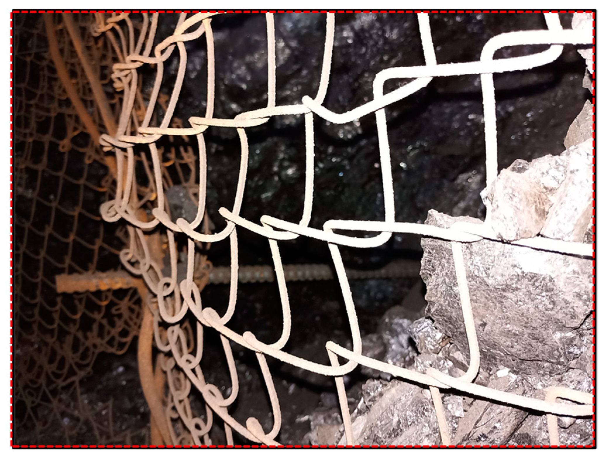
The joints and fissures in the coal mass near the panel n. 218 are significantly developed, with low cohesion, strength, and bearing capacity. The surrounding rock of the coal roadway is soft and fractured, which poses great difficulties in controlling the stability of the surrounding rock. In addition, the size of the coal pillar and the design of the surrounding rock support plan for the coal roadway in the panel n. 220 are mainly based on on-site practical experience, lacking theoretical support, causing severe instability and damage to the coal pillar and support system of the coal roadway. The primary manifestation is that the coal mass on the roadway rib bulges outward significantly and causes severe damage to the support system, as shown in Figure 3.
The on-site engineering practice has confirmed that the panel n. 220 mining roadway adjacent to panel n. 218 cannot meet the production needs of the mine under the original support method and coal pillar size. Therefore, if the coal pillar size and surrounding rock support design of the panel n. 218 is still copied, the parameters of the panel n. 220 will inevitably cause large-scale deformation and damage to the surrounding rock and support system of the roadway, seriously affecting the normal production of the mine. There is an urgent need to seek reasonable coal pillar size and new support methods and processes to solve the production problems in mines.

3. Determination of GSED Coal Pillar Size in Deep Soft Coal Seams

3.1. Theoretical Calculation

(1)
The relationship between the main roof breaking line position and the coal pillar size.
The mining of the previous panel causes the main roof to break and interlock with each other to form a stable articulated structure. The breaking line divides the coal mass into two plates [31,32], namely the internal stress field S1 and the external stress field S2, as shown in Figure 4.
To ensure the safe bearing of a coal pillar, the relationship between the internal stress field width and the coal pillar size and roadway size meets the following equation:
S 1   L 1 + L 2
where L1 is the size of the coal pillar and L2 is the roadway width.
The following equation determines the range of the internal stress field [33]:
S 1 = 6 γ a M L G 0 y 0
In the above Formula (2), L is the initial pressure step distance of the main roof, 48 m; M is the main roof thickness, 6.3 m; a is the length of the panel, 260 m; γ is the average unit weight of the main roof, 25,000 N/m3; y0 is the compression value of the coal wall, 0.8 m; and G0 is the stiffness of the coal body around the roof fracture line, 1.1 × 10⁹ Pa. The calculation shows that S1 is 13.4 m, and because L2 is 5.0 m, the maximum size of the coal pillar is 8.4 m.
(2)
Relationship between limit equilibrium zone and coal pillar size.
In addition, if the size of the reserved coal pillar is too small, it will cause severe destruction of the coal pillar in the process of overburdening activities, leading to the instability of anchor cable anchorage points, and the stability of the coal pillar is challenging to maintain until the complete loss of bearing capacity. Therefore, the size of the coal pillar must also meet the following equation:
L 1     x 1 + x 2 + x 3
In the above Formula (3), x3 is the stability coefficient of the coal pillar, which calculation method is 0.2 (x1 + x2), m; x2 is the effective anchoring length of the bolt support component in the coal mass, 1.8 m; and x1 is the range of coal pillar crushing area, m. The analytical expression for x1 is as follows [34]:
x 1 = m A 2 tan φ l n ( k γ H   + C / tan φ C tan φ + p A )
In the above Formula (4), A is the pressure coefficient, A = μ/(1 − μ), μ is Poisson ratio, 0.2; m is the mining thickness of the coal seam, 4.28 m; K is the stress concentration coefficient, 1.3; H is the buried depth of the roadway, 686 m; γ is the average unit weight of the rock layer, 25 kN/m3; φ is the internal friction angle of the coal seam interface, 19°; p is the support resistance to the roadway wall, 0.32 MPa; and C is the cohesive force at the coal seam interface, 1.02 MPa. Based on the data from the panel n. 218, x1 = 2.76 m, and substituting into Equation (3), the minimum size of the coal pillar is 5.47 m. Therefore, the reasonable size range of narrow coal pillars should be 5.47–8.40 m.

3.2. Numerical Calculation Analysis

3.2.1. Numerical Model

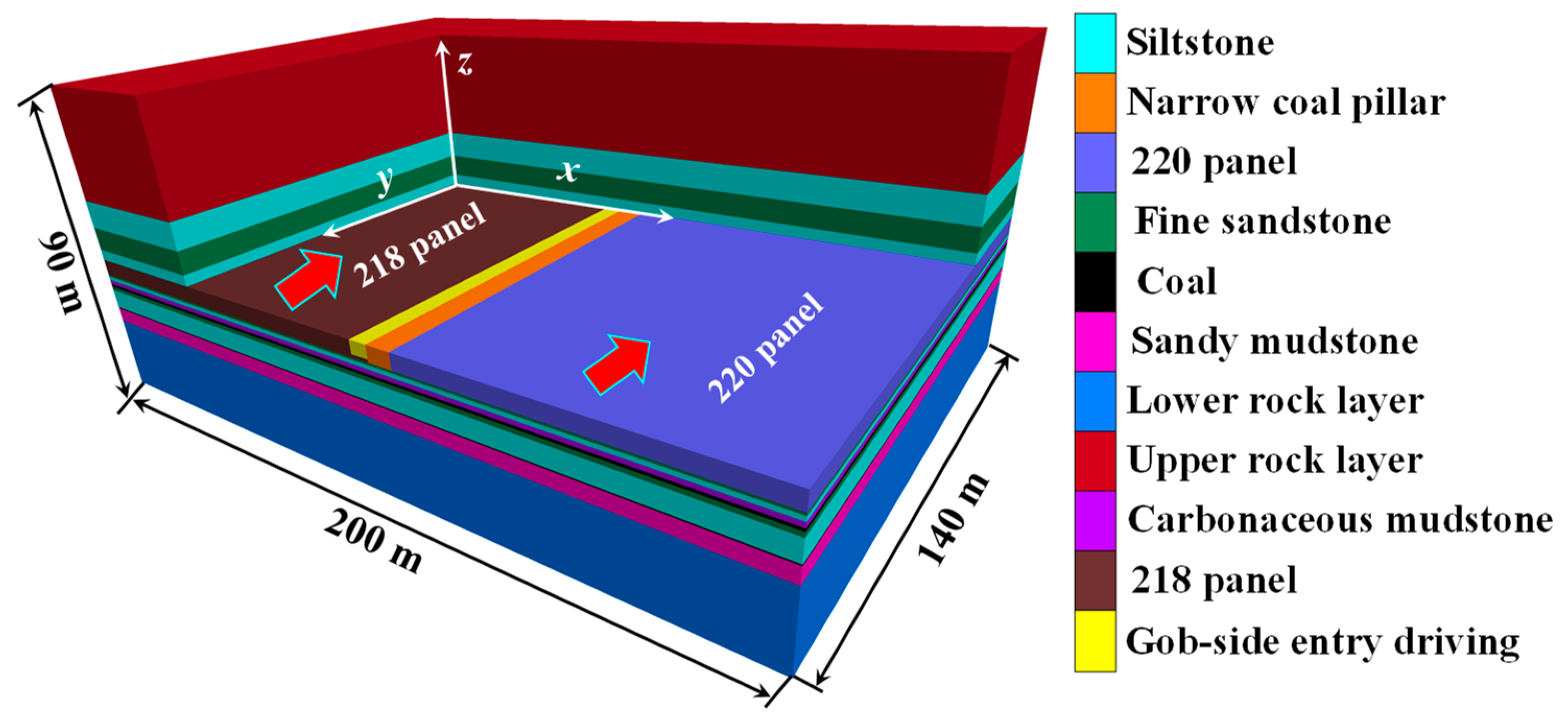
Based on the actual engineering conditions of the mine, establishing the numerical calculation model (x × y × z = 200 m × 140 m × 90 m) is shown in Figure 5. The panel is mining in the negative y-axis direction. The top boundary of the model is the stress boundary. The remaining boundaries are the fixed speed boundary. This numerical model simulates the response characteristics of the deviatoric stress and plastic failure field in the GSED surrounding rock when the coal pillar size is 3, 4.5, 6.5, 9, 11, and 13 m, respectively. The constitutive equation of the model adopts Mohr Coulomb’s essential criterion.
As the indoor mechanical test results cannot be directly used for numerical simulation, the determination of mechanical parameters of rock mass in numerical simulations is obtained by calculating and processing the mechanical parameters measured in the laboratory based on Hoek Brown’s essential criteria. The processed data results are shown in Table 1.

3.2.2. Superiority of Deviatoric Stress Analysis Indicator

Based on elastic-plastic mechanics, the stress states at a certain point in a rock mass are mainly deviatoric stress and spherical stress. The deviatoric stress controls the shape change of the rock mass (plastic deformation and failure of the rock mass). The spherical stress controls the volume change of the rock mass (recoverable elastic deformation of the rock mass) [35]. If we assume three principal stresses perpendicular to each other is σi (i = 1, 2, 3), σ1σ2σ3. The stress at a certain point in the rock mass is described as follows:
σ 1 0 0 0 σ 2 0 0 0 σ 3 = σ m 0 0 0 σ m 0 0 0 σ m + s 1 0 0 0 s 2 0 0 0 s 3
In the above Formula (5), σm is the tensor component of spherical stress, which is used as a parameter to measure spherical stress in this paper. Its relationship with principal stress is determined as follows:
σ m = 1 3 σ 1 + σ 2 + σ 3
si is the tensor component of the main deviatoric stress ( s i =   σ i σ m ), where si plays the most important role in the deformation and failure of surrounding rock, and s1 is the maximum deviatoric principal stress. It simultaneously considers the interaction between the maximum, intermediate, and minimum principal stress. The relationship between the maximum deviatoric principal stress and the principal stress is determined as follows:
s 1 = σ 1 1 3 σ 1 + σ 2 + σ 3
After excavation, the shear stress of the shallow surrounding rock of the roadway is concentrated, and the surrounding rock releases energy and unloads. The unloading process will inevitably generate deviatoric stress. The deviatoric stress is a combination of horizontal, vertical, and tangential stresses, which can be used to characterize the distribution of shear stress of materials under load, revealing that the essential force source of rock mass deformation and failure is mainly caused by shear stress. Given this, this paper takes the maximum deviatoric principal stress as an analysis index and uses it as a parameter to measure the stability of surrounding rock, studying and determining the size of coal pillars.

3.2.3. Failure Characteristics of GSED under Different Coal Pillar Sizes

(1)
Distribution characteristics and evolution law of deviatoric stress.
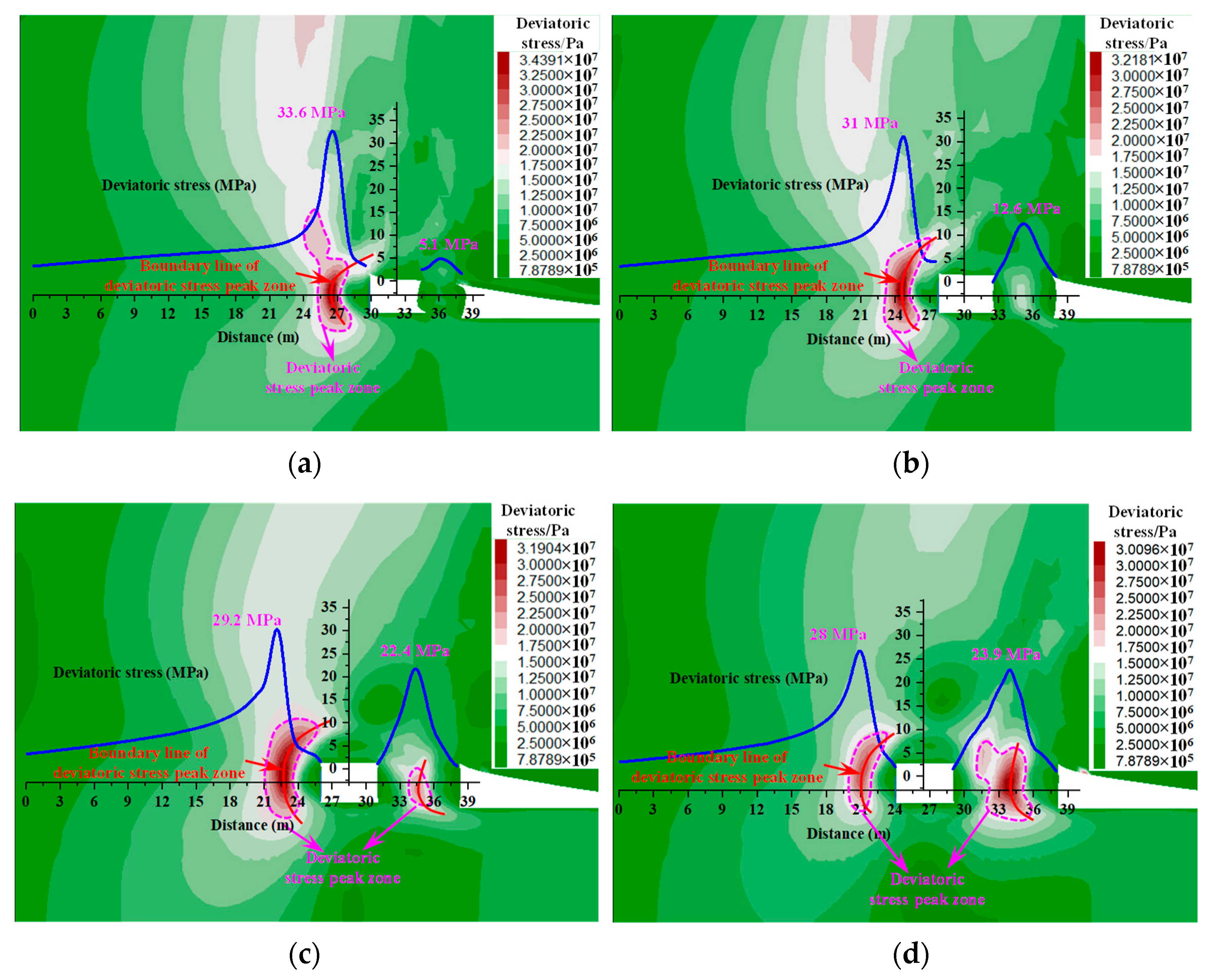
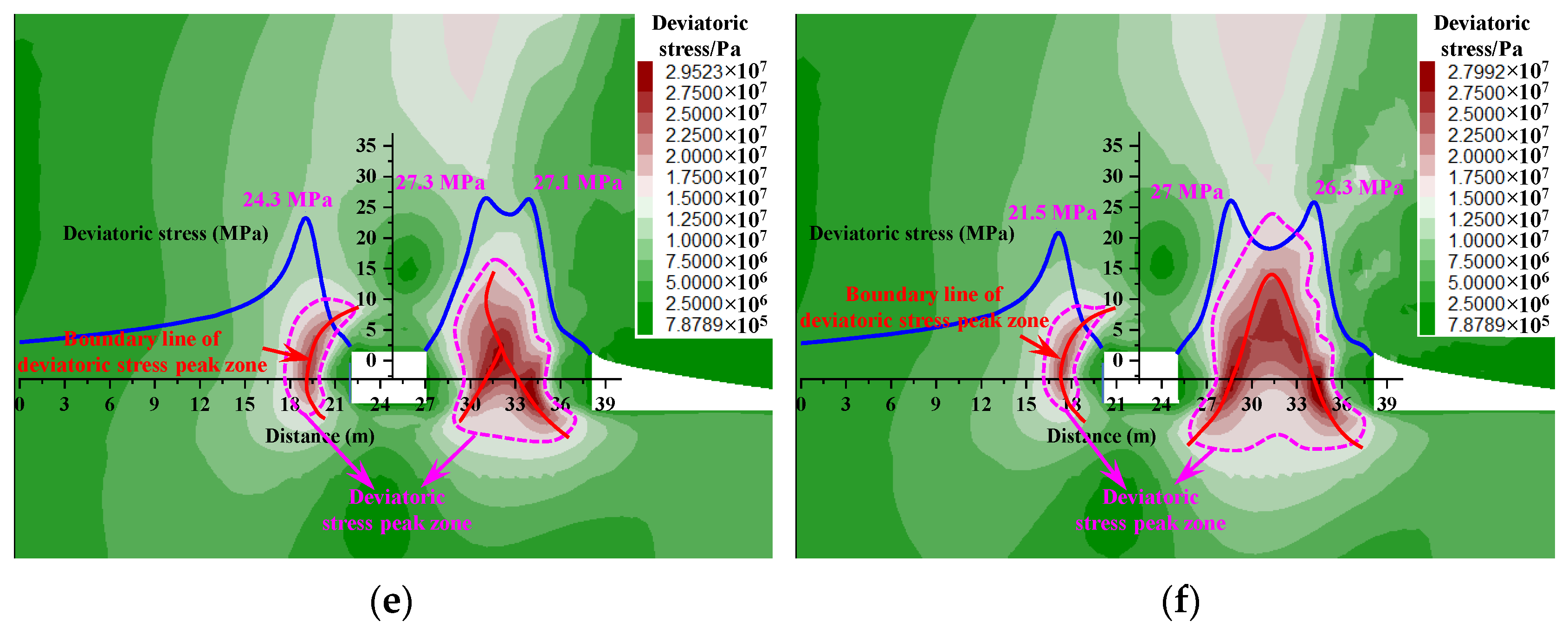
From Figure 6, the deviatoric stress state of the surrounding rock at the roof and floor of the roadway does not change with the size of the coal pillar. The deviatoric stress state of the roof and floor under different coal pillar sizes are in an extensive range of low deviatoric stress states. However, under different coal pillar sizes, there are peak deviatoric stress bands on both the coal pillar rib and the entity coal rib. The concentration degree of the peak deviatoric stress band on the coal pillar increases with the increase in the coal pillar size. The concentration degree of the peak deviatoric stress band on the entity coal rib decreases with the increase in the coal pillar size.
When the size range of the coal pillar is between 3 and 4.5 m, the peak band of deviatoric stress is mainly concentrated on the entity coal rib; nevertheless, the stress on the coal pillar is relatively weak. The peak deviatoric stress on the entity coal rib exceeds 31 MPa, but the peak deviatoric stress on the coal pillar rib is less than 13 MPa. The bearing capacity of the coal pillar is insufficient, leading to the severe deformation of the roadway coal rib.
When the size range of the coal pillar is between 6.5 and 9 m, the peak band of deviatoric stress exists simultaneously on the coal pillar and the entity coal rib. The peak range of deviatoric stress on the coal pillar rib is between 22.4 MPa and 23.9 MPa, which enhances the stress on the coal pillar and significantly increases its bearing capacity compared to the size range of the coal pillar of 3~4.5 m. The coal pillar plays an essential role in supporting the roof, ensuring the GSED surrounding rock and coal pillar stability.
When the size range of the coal pillar is between 11 and 13 m, the concentration of the peak deviatoric stress band is significantly weakened on the entity coal rib, and the peak deviatoric stress gradually decreases. The range of peak deviatoric stress bands on the coal pillar rib increases, and the phenomenon of deviatoric stress concentration is more evident on the coal pillar rib. The peak deviatoric stress on the coal pillar rib shows a double peak distribution. In this case, the high deviatoric stress concentration inside the coal pillar poses a significant threat to the coal pillar stability, which is not conducive to controlling the deformation of the GSED.
(2)
Distribution characteristics and evolution law of plastic zone.
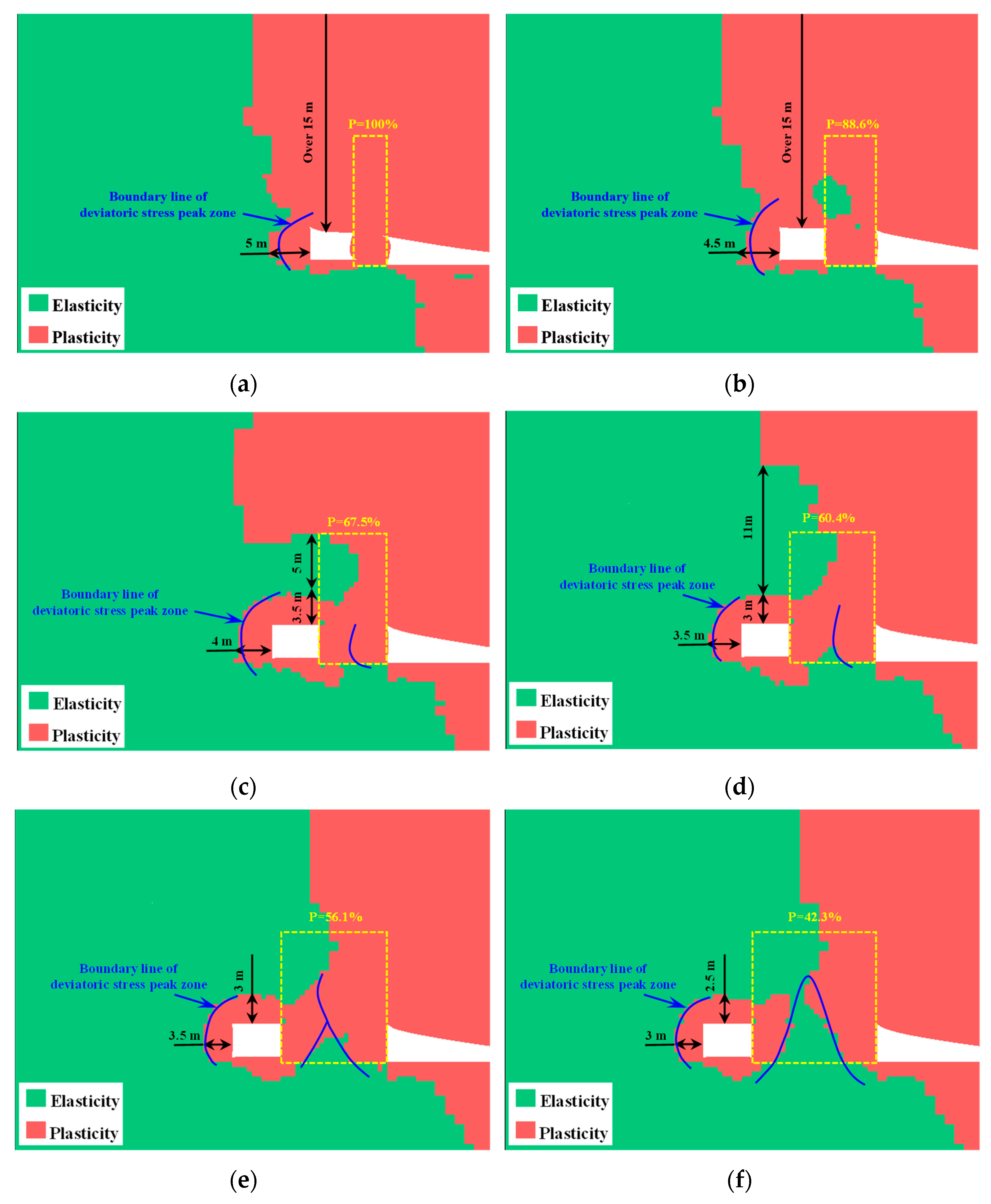
From Figure 7, when the size of the coal pillar ranges from 3 to 4.5 m, the roof, the entity coal rib, and the coal pillar rib of the roadway undergo extensive shear plastic damage due to the influence of the previous panel mining and roadway excavation. The coal pillar rib undergoes severe internal extrusion deformation. When the size of the coal pillar is 3 m, the depth of the plastic zone on the roadway roof exceeds 15 m, the depth of the plastic zone on the entity coal rib is 5 m, and the plasticization degree of the coal pillar is 100%. When the size of the coal pillar is 4.5 m, the depth of the plastic zone on the roadway roof exceeds 15 m, the depth of the plastic zone on the entity coal rib is 4.5 m, and the plasticization degree of the coal pillar is 88.6%.
When the size of the coal pillar ranges from 6.5 to 9 m, the plastic zone of the entity coal rib above the coal pillar and the roadway roof significantly decreases, and an elastic core zone appears in the roof. When the size of the coal pillar is 6.5 m, the depth of the plastic zone of the entity coal rib is 4 m, the plasticization degree of the coal pillar is 67.5%, the depth of the plastic zone of the roof is 3.5 m, and an elastic zone with a size of 5 m appears above the roof. At a coal pillar size of 9 m, the depth of the plastic zone of the entity coal wall is 3.5 m, the plasticization degree of the coal pillar is 60.4%, the depth of the plastic zone of the roof is 3 m, and an elastic zone with a size of 11 m appears above the roof. In this case, if 8.5 m and 4.5 m long anchor cables are, respectively, applied to the roof and the entity coal rib of the roadway, the anchor cables will be anchored in the elastic zone of the coal rock mass, which can significantly exert the anchoring effect.
When the size of the coal pillar ranges from 11 to 13 m, the plastic failure coal mass inside the coal pillar gradually transitions to elastic coal mass, and the degree of coal pillar damage is significantly reduced. The plastic zone of the entity coal rib and roof of the roadway also correspondingly decreases. At a coal pillar size of 11 m, the plastic zone depth of the entity coal rib is 3.5 m, the plasticization degree of the coal pillar is 56.1%, and the plastic zone depth of the roof is 3 m. At a coal pillar size of 13 m, the plastic zone depth of the entity coal rib is 3 m, the plasticization degree of the coal pillar is 42.3%, and the plastic zone depth of the roof is 2.5 m. When the size of the coal pillar increases to more than 13 m, a more extensive range of elastic core areas appears inside the coal pillar, and the plastic zone around the roadway no longer intersects with the plastic zone of the coal pillar. However, under these coal pillar sizes, the peak concentration of deviatoric stress inside the coal pillar is relatively high, which is not conducive to maintaining the stability of the roadway. Moreover, vast coal pillars can cause resource waste and economic loss.
From a numerical simulation perspective, the coal pillar’s reasonable size should be within the range of 6.5 to 9 m. Within this range, the coal pillar has good stress environment and roof support conditions, which can fully utilize the support effect of anchor cables and reduce the size of the coal pillar and the proportion of resource waste.

3.3. Optimal Design of Narrow Coal Pillar Size in GSED

According to the internal and external stress fields and the limit balance theory, under the condition of ensuring that the coal pillar and roadway are in the stress low-value zone and the coal pillar has a self-stabilizing ability, the maximum size of the narrow coal pillar under this geological condition is 8.40 m, and the minimum size is 5.47 m. In addition, numerical model simulations were conducted on the deviatoric stress and plastic failure characteristics of the surrounding rock of the roadway when the narrow coal pillar size was 3, 4.5, 6.5, 9, and 11 m, respectively. The numerical analysis showed that when the coal pillar size was between 6.5 and 9 m, the stress state of the coal pillar was improved, and the bearing conditions were excellent. There were elastic core areas above the coal pillar and the roadway roof, and the plastic zone depth of the entity coal rib was controlled within 4 m. It can significantly exert the anchoring effect of anchor cables to ensure the roadway roof and rib stability. Based on the intersection of theoretical calculation and numerical analysis results, while considering engineering analogy and economic benefits, it is comprehensively determined that the size of the GSED narrow coal pillar is 6.5 m. The changes in indicators under different coal pillar sizes are shown in Figure 8.

4. Failure Characteristics of GSED Surrounding Rock of the Advanced Panel

Based on the study of the distribution and evolution law of plastic zone and deviatoric stress under different coal pillar sizes, it can be concluded that the optimal coal pillar size is 6.5 m. This section will explore the distribution status of deviatoric stress and the plastic zone in the surrounding rock of the roadway in front of the panel during mining, providing a basis for the rational determination of support parameters. We sliced and analyzed the deviatoric stress and plastic zone for different distances from the advanced panel. The slicing position is shown in Figure 9.
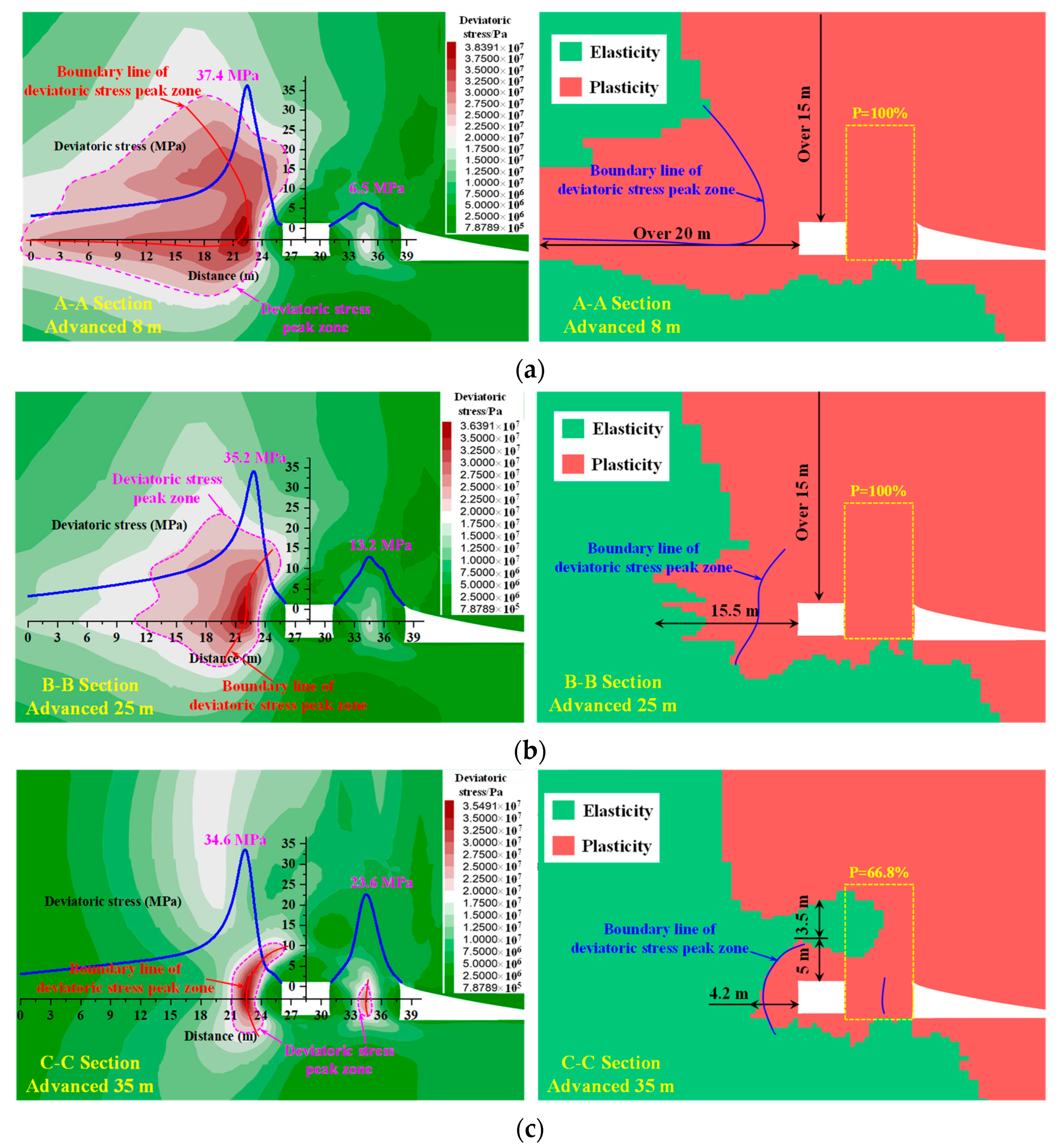
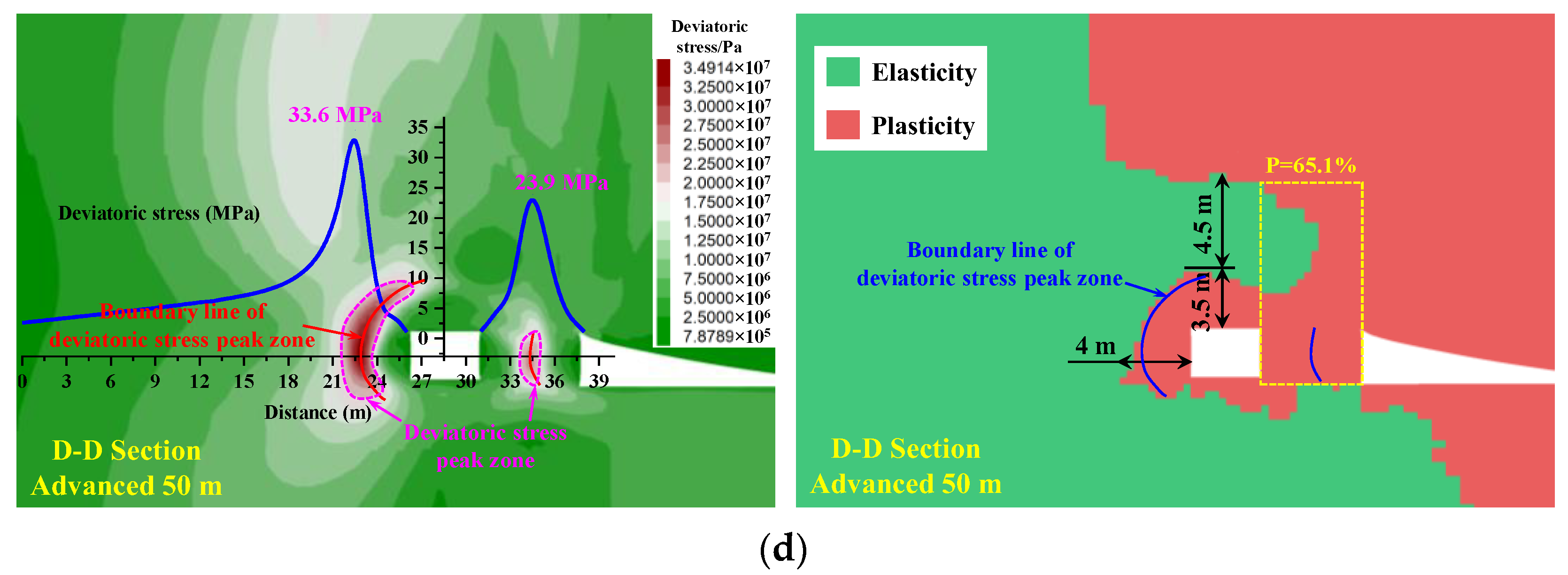
The distribution of deviatoric stress and plastic zone at different positions of the advanced panel is shown in Figure 10.
(1)
The closer the panel is, the greater the concentration of the peak deviatoric stress band, and the peak deviatoric stress band is mainly concentrated on the entity coal rib. Therefore, the entity coal rib primarily bears the overlying load pressure.
(2)
The range of peak deviatoric stress zone on the entity coal rib of the roadway within the 25 m range of the advanced panel is large, and the peak deviatoric stress on the entity coal rib is large, reaching over 35 MPa, whereas the deviatoric stress on the coal pillar rib is weak, less than 14 MPa. The plastic zone depth of the roadway entity coal rib and roof within the 25 m range of the advanced panel exceeds 15 m, and the plasticization degree of the coal pillar is 100%. The roadway within this section is severely damaged and requires advanced support. This project uses single hydraulic supports for advanced support to maintain normal coal production.
(3)
The deviatoric stress on the entity coal rib and coal pillar rib of the roadway outside the range of 35 m ahead of the panel gradually stabilizes, with a peak deviatoric stress on the entity coal rib of about 34 MPa. The deviatoric stress state on the coal pillar rib is excellent, about 24 MPa. When the advanced panel distance is 35 m, the plastic zone depth on the entity coal rib of the roadway is 4.2 m, the plasticization degree of the coal pillar is 66.8%, the plastic zone depth on the roof is 5 m, and an elastic zone with a size of 3.5 m appears above the roof. When the advanced panel distance is 50 m, the plastic zone depth on the entity coal rib of the roadway is 4 m, the plasticization degree of coal pillar is 65.1%, the plastic zone depth on the roof is 3.5 m, and an elastic zone with a size of 4.5 m appears above the roof.
It can be seen that, under the violent mining influence of the panel, the surrounding rock of the roadway within a range of 25 m ahead of the panel is severely damaged, and it is necessary to strengthen support to control the unstable surrounding rock of the roof and rib. The support plan for the surrounding rock of the roadway outside the 35 m range of the advanced panel needs to be designed explicitly based on the plastic zone and deviatoric stress distribution characteristics of the surrounding rock of the GSED, ensuring the safety and standard production of the coal mining face.

5. Control Technology of GSED Surrounding Rock

Clarifying the plastic zone and deviatoric stress range, development, and evolution characteristics of the roadway surrounding rock has important guiding significance for the rational and differentiated support design of the surrounding rock in various parts of the underground roadway.

5.1. Thoughts on Support Design

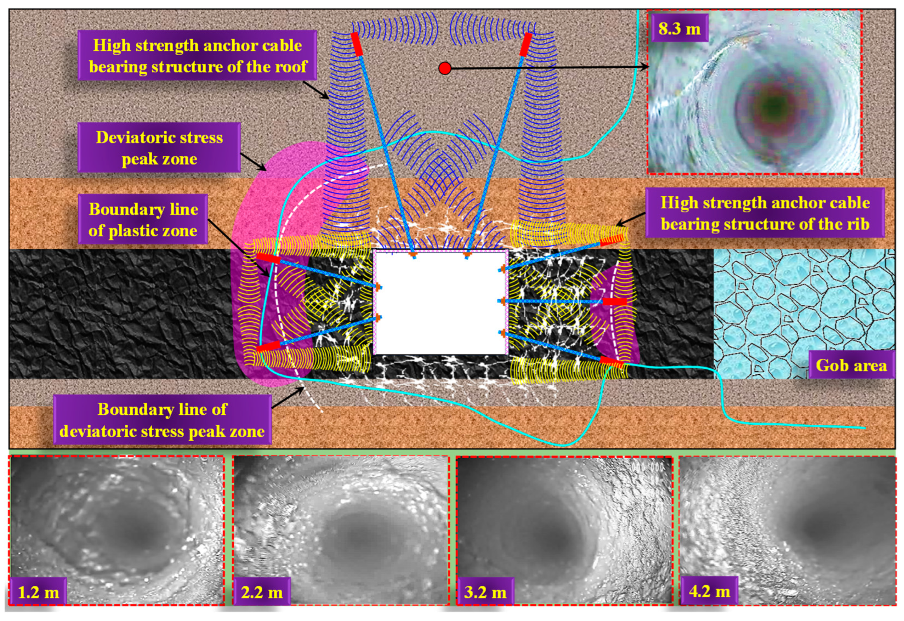
The distribution of the boundary line of the peak deviatoric stress zone, and the contour line of the plastic zone in the surrounding rock after the excavating stability of the panel n. 218 with small coal pillars, is shown in Figure 11.
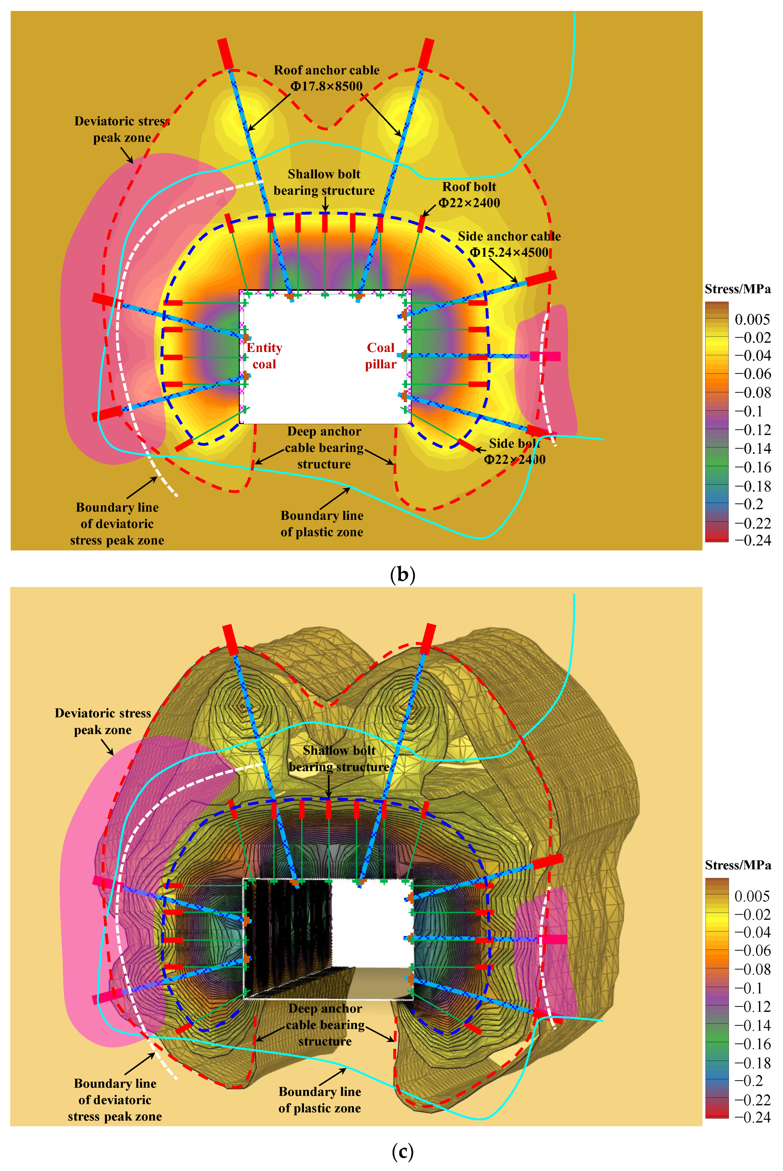
From this, it can be seen that, after the excavation of the roadway and panel is stable, the plastic zone maximum depth of the roof and entity coal is about 3.5 m and 4 m, respectively. The plasticization degree of the coal pillar rib is about 67.5%. The boundary line of the peak deviatoric stress zone on the entity coal rib is about 3.5 m from the roadway’s surface, and the boundary line of the peak deviatoric stress zone on the coal pillar rib is about 3.8 m from the roadway’s surface. In addition, the numerical simulation results indicate that there is a trend of roof plastic zone depth expansion in the GSED surrounding rock deeper part. Therefore, drilling crack detection was conducted on the surrounding rock of the GSED roof and rib, and the crack development range and degree were obtained. The peeping results show that the rock integrity is good at a depth of 8.3 m in the roof, without apparent cracks. The roof anchor cable anchored at this position will have an excellent anchoring effect. There is a certain degree of fragmentation and various irregular cracks in the surrounding rock within the range of 3.2 m of the entity coal rib. The coal mass of the roadway rib is relatively complete at a depth of 4.2 m, and the rib anchor cable anchored at this position will have an excellent anchoring effect. However, the development of shallow cracks inside the coal pillar is more pronounced than inside the entity coal rib, and the coal pillar must be supported by reinforced anchor cables to maintain the integrity of the shallow surrounding rock.
It can be seen that the damage degree of the coal pillar rib is much greater than that of the entity coal rib. The key area for controlling the GSED surrounding rock is the coal pillar rib. When supporting, it is necessary to reinforce the coal pillar rib. It needs to make the anchor cable pass through the boundary line of the deviatoric stress peak zone of the surrounding rock and the contour line of the plastic zone on the entity coal rib to anchor in the relatively intact rock mass, making the anchor foundation more stable.

5.2. Control Measures for Surrounding Rock

The support countermeasures analysis of GSED is shown in Figure 12.
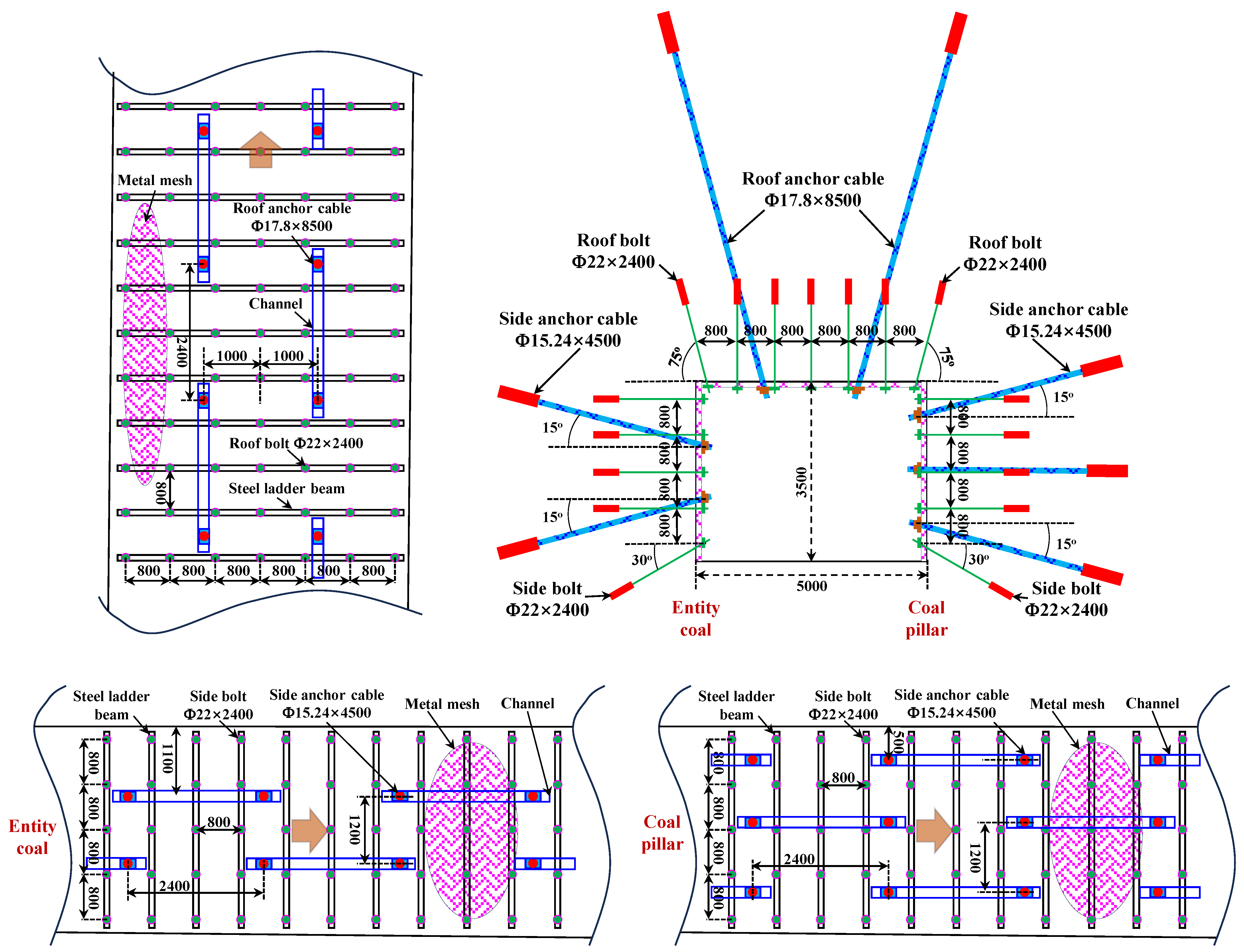
Considering that the test roadway will experience the severe dynamic pressure disturbance caused by the mining face, it is determined that the rib asymmetric channel steel truss anchor cable form will be used for the surrounding rock control of the panel n. 218 GSED. Two anchor cables Φ15.24 × 4500 mm are arranged on the entity coal rib (the inclined arrangement of the top and bottom anchor cables can achieve an excellent anchoring effect). Three anchor cables Φ15.24 × 4500 mm are arranged on the coal pillar rib (the inclined arrangement of the top and bottom anchor cables can achieve an excellent anchoring effect). The roof adopts a combined support form of bolts and anchor cables, with the arrangement of two long anchor cables Φ17.8 × 8500 mm (the inclined arrangement of anchor cables on both sides of the roof can achieve an excellent anchoring effect).
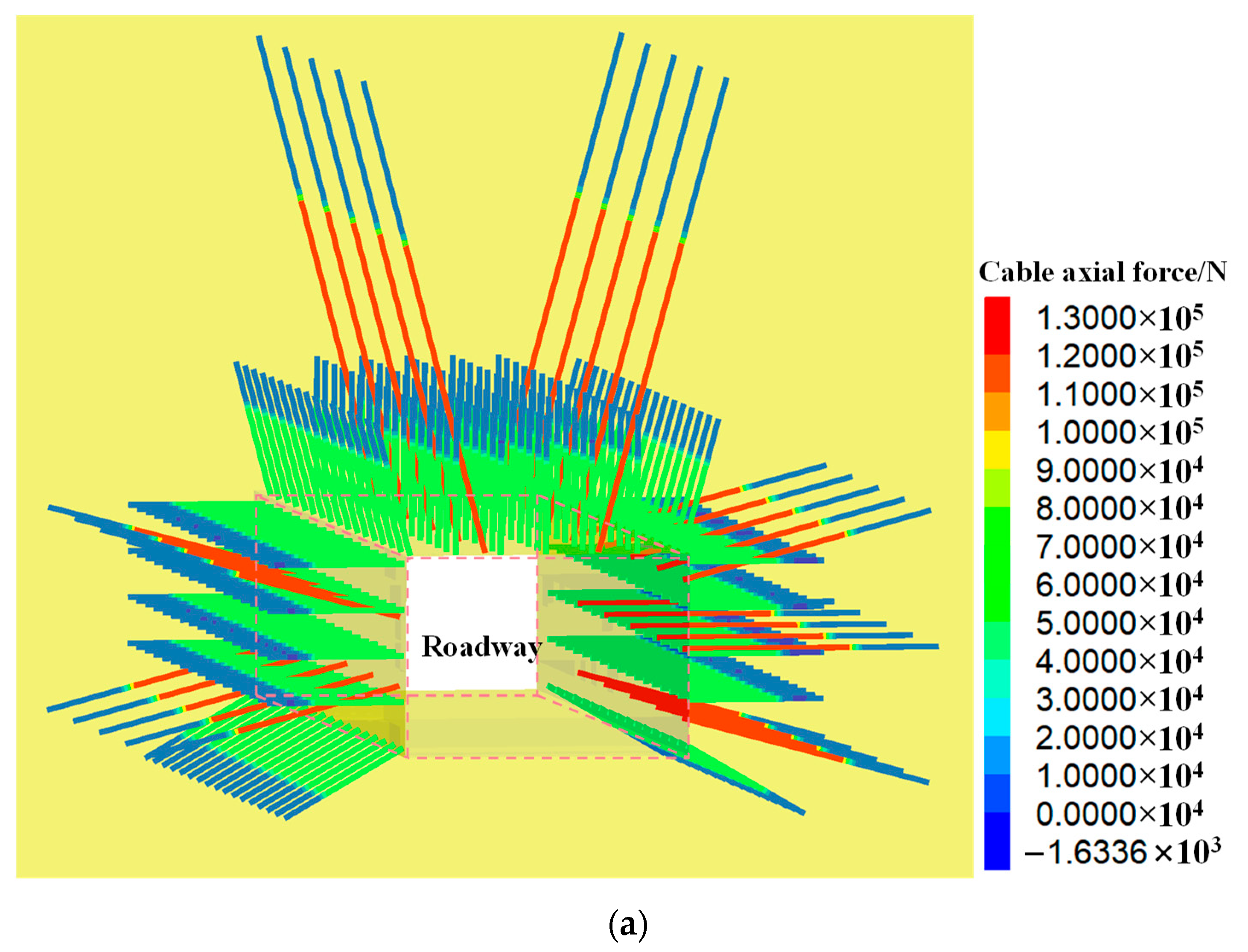
The bolt and anchor cable of the roadway roof and rib forms a high-strength anchoring bearing structure. The high-strength anchoring bearing structure of the GSED surrounding rock is a unified bearing structure formed by bolt support, anchor cable support, and the surrounding rock of the roadway. This structure is characterized by the mutual compression between bolts and bolts in the shallow surrounding rock. The bolts use trays and steel mesh to protect and support the rock mass in the fractured area of the shallow surrounding rock, preventing the shallow fractured rock mass from being squeezed out, thus forming a shallow bearing structure. In addition, the application of prestressed long anchor cables not only strengthens the load-bearing structure of shallow bolts but also applies lateral forces to the shallow load-bearing structure to improve its load-bearing capacity. At the same time, the anchor cables can also form a load-bearing structure in the deeper surrounding rock, improving the load-bearing capacity of the surrounding rock and the anchoring zone. Based on improving the load-bearing capacity of the surrounding rock and the anchoring zone, it can also transfer some of the stress on the load-bearing structure to the deeper part of the surrounding rock, thus achieving a coordinated working state with the deep rock mass, further strengthening the anchoring bearing structure. Therefore, the formation of the high-strength anchoring load-bearing structure in the GSED surrounding rock can be seen as the superposition and coupling of the prestressed bearing structure generated by the bolts and cables support in the surrounding rock, as shown in Figure 13. The mechanical action range of this high-strength load-bearing structure can cover the peak deviatoric stress zone of the surrounding rock of the roadway, playing an active reinforcement role in the areas where the surrounding rock is prone to damage and suppressing the sustained destruction of the roadway’s surrounding rock.

5.3. Support Programme of GSED Surrounding Rock

A joint control technology for surrounding rock has been proposed to control the deformation of the GSED surrounding rock, which includes a combination of a roof channel steel anchor beam mesh, a rib asymmetric channel steel truss anchor cable beam mesh, a grouting modification in local fractured areas, and an advanced strengthened support using a single hydraulic support, as shown in Figure 14.
Roof channel steel anchor beam mesh support: a diamond-shaped metal mesh is laid on the roadway roof and ribs, and H-shaped steel strip beams are hung perpendicular to the axial direction of the roadway. The roof and ribs bolt adopts Φ22 × 2400 mm high-strength threaded steel bolts with a spacing of 0.8 m × 0.8 m, with an anchoring force of no less than 15 tons and a torque of no less than 300 Nm. The roof anchor cable adopts two-channel steel anchor cables arranged in a staggered interlocking manner along the roadway axial direction. Each anchor cable is arranged 1 m away from the middle of the roadway, with a spacing of 2.4 m. The specifications of the roof anchor cable are a Φ17.8 × 8500 mm steel strand anchor cable, with a preload of no less than 130 kN.
Rib asymmetric channel steel truss anchor cable beam mesh: two anchor cables, Φ15.24 × 4500 mm, are arranged on the entity coal rib (the inclined arrangement of the top and bottom anchor cables can achieve an excellent anchoring effect). Three anchor cables, Φ15.24 × 4500 mm, are arranged on the coal pillar rib (the inclined arrangement of the top and bottom anchor cables can achieve an excellent anchoring effect), with a row spacing of 1.2 m × 2.4 m. The specifications of the rib anchor cable are a Φ15.24 × 4500 mm steel strand anchor cable, with a preload of no less than 130 kN.
Grouting modification in local fractured areas: when encountering coal and rock fragmentation and the surrounding rock is prone to large deformation and damage, anchor cables on the roadway roof and two sides are replaced with grouting anchor cables to modify and reinforce the surrounding rock. Before grouting, spraying concrete to seal the surface fractured coal and rock mass of GSED is necessary. Grouting pressure of about 3 MPa and a slurry diffusion radius of about 1.5–2.0 m are set, improving the compressive and shear properties of the coal rock mass.
Advanced strengthened support by single hydraulic support: the roadway within the 25 m range of the advanced panel is severely damaged, and single hydraulic supports are used for advanced support to maintain the normal functioning of the roadway.

5.4. Engineering Application

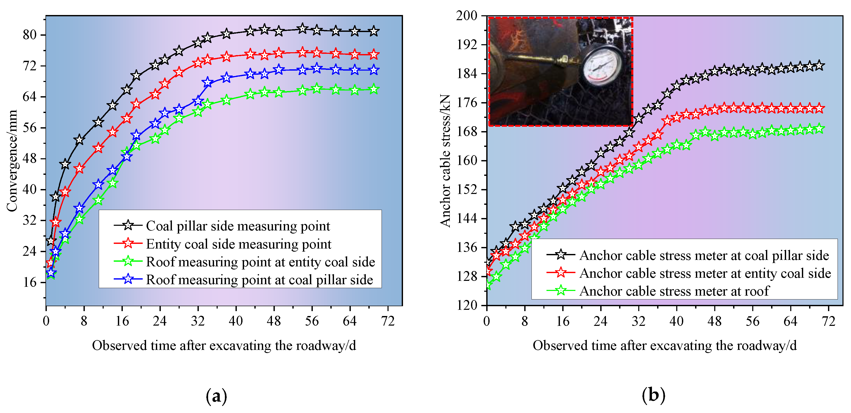
Continuous mine pressure monitoring was carried out to understand the deformation status of the surrounding rock and the stress environment characteristics of the support structure of GSED. The displacement of the surrounding rock and the stress change curve of the anchor cable after the roadway excavation is shown in Figure 15.
From Figure 15, with the passage of time, the surface deformation of the surrounding rock of the roadway and the stress of the anchor cable gradually increase. About 43 days after the completion of the support, the surface deformation of the surrounding rock of the roadway and the stress of the anchor cable tend to be stable, in which the deformation and the stress of the anchor cable of the coal pillar rib are the largest, and the maximum values are about 81 mm and 186 kN, respectively.
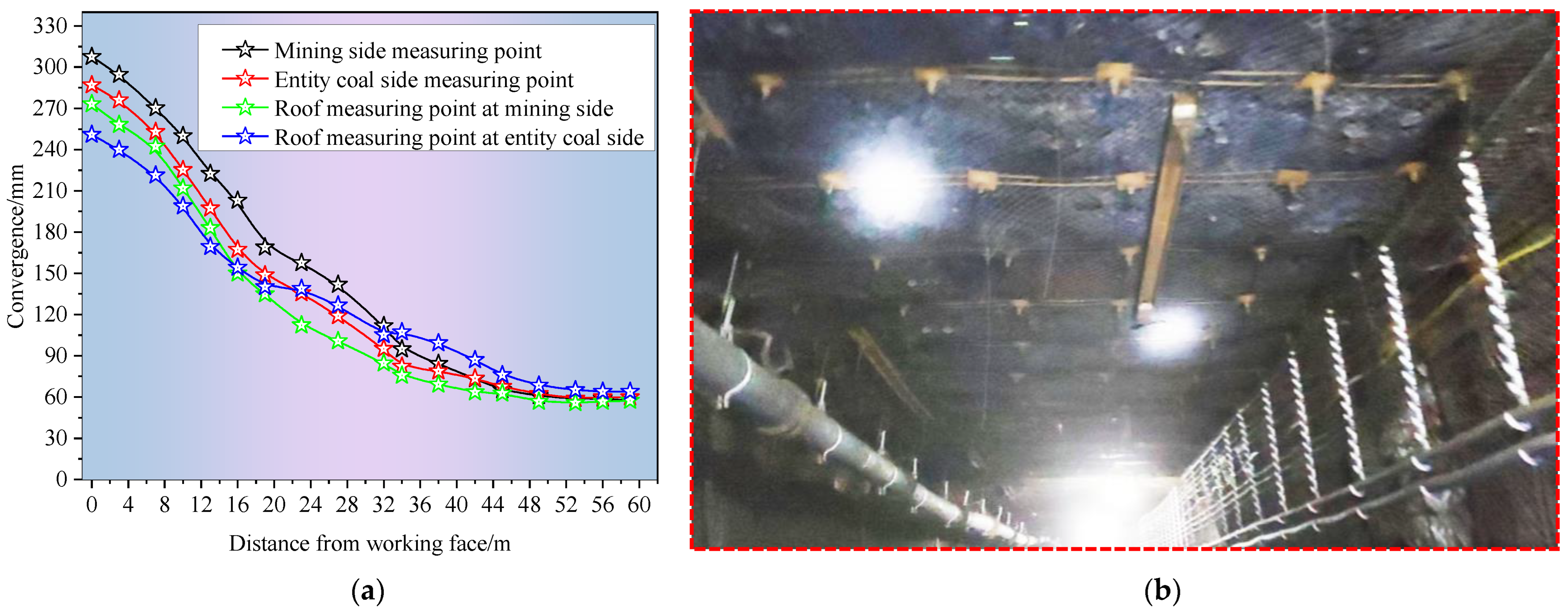
In addition, during the mining of the panel, the displacement change curve of the surrounding rock of the roadway during the influence of the advanced dynamic pressure of the panel is shown in Figure 16a.
Affected by the advanced pressure of this panel, the surface deformation of the roadway will increase. As the panel advances, the distance between the panel and the monitoring section will continue to shrink, and the deformation of the surrounding rock will gradually increase. Most of the deformation is formed within a range of 50 m from the panel. At the same time, the maximum deformation of the four measuring points in the roadway is about 307 mm, 287 mm, 273 mm, and 250 mm, respectively. In summary, the deformation of the surrounding rock after roadway support is within a controllable range, and the cross-sectional size meets the usage standards for roadway ventilation, pedestrians, and transportation.
The control effect of surrounding rock in the GSED of the panel n. 218 is shown in Figure 16b. It has been confirmed through engineering practice that the above overall reinforcement technology can control the deformation of the surrounding rock. The coal rock mass of the roof and the two sides are flat and intact. The control effect of the surrounding rock of the roadway is good.

6. Conclusions

(1)
Under the condition of ensuring that the coal pillar and roadway are in the stress low-value zone and the coal pillar has a self-stabilizing ability, the maximum size of the narrow coal pillar under this geological condition is 8.40 m, and the minimum size is 5.47 m. Numerical analysis shows that the reasonable size of the coal pillar should be within the range of 6.5 to 9 m. Within this range, the coal pillar has an excellent stress environment and roof support conditions, which can fully utilize the support effect of anchor cables. Based on the intersection of theoretical calculation and numerical analysis results, it is comprehensively determined that the size of the GSED narrow coal pillar is 6.5 m.
(2)
The disturbance of the mining face results in the peak deviatoric stress zone mainly concentrated on the entity coal rib, and the entity coal rib mainly bears the overlying load pressure. During mining, the surrounding rock of the roadway within a range of 25 m ahead of the panel is severely damaged, and it is necessary to strengthen support to control the unstable surrounding rock of the roof and rib.
(3)
After the excavation of the roadway and panel is stable, the plastic zone maximum depth of the roof and entity coal rib is about 3.5 m and 4 m, respectively. The plasticization degree of the coal pillar rib is about 67.5%. The boundary line of the peak deviatoric stress zone on the entity coal rib is about 3.5 m from the surface of the roadway, and the boundary line of the peak deviatoric stress zone on the coal pillar rib is about 3.8 m from the surface of the roadway.
(4)
The rock integrity is good at a depth of 8.3 m in the roof, without obvious cracks. The roof anchor cable anchors at this position will have an excellent anchoring effect. There is a certain degree of fragmentation and various irregular cracks in the surrounding rock within the range of 3.2 m of the entity coal rib. The coal mass of the roadway rib is relatively complete at a depth of 4.2 m, and the rib anchor cable anchors at this position will have an excellent anchoring effect. The development of shallow cracks inside the coal pillar is more pronounced than in the entity coal rib. The key area for controlling the GSED surrounding rock is the coal pillar rib.
(5)
The support design of the GSED needs to make the anchor cable pass through the boundary line of the deviatoric stress peak zone of the surrounding rock and make the contour line of the plastic zone on the entity coal rib anchor into the relatively intact rock mass. Joint control technology for surrounding rock is proposed, which includes a combination of a roof channel steel anchor beam mesh, a rib asymmetric channel steel truss anchor cable beam mesh, a grouting modification in local fractured areas, and an advanced strengthened support using a single hydraulic support, effectively controlling the deformation of the surrounding rock.

Author Contributions

Writing—original draft preparation, Z.J. and W.G.; writing—review and editing, Z.J.; supervision, S.X.; funding acquisition, S.X. All authors have read and agreed to the published version of the manuscript.

Funding

This research was funded by the National Natural Science Foundation of China (No. 52074296), the Fundamental Research Funds for the China University of Mining and Technology (Beijing)-Top Innovative Talents Cultivation Fund for PhD Candidate (No. BBJ2023003), and the Fundamental Research Funds for the Central Universities (No. 2022YJSNY18).

Data Availability Statement

The datasets generated or analyzed during the current study are available from the corresponding author upon reasonable request.

Acknowledgments

The author team thanks the field technicians for providing the field test conditions and the ground pressure observation conditions.

Conflicts of Interest

The authors declare that they have no conflict of interest.

References

  1. Batugin, A.; Wang, Z.Q.; Su, Z.H.; Sidikovna, S.S. Combined support mechanism of rock bolts and anchor cables for adjacent roadways in the external staggered split-level panel layout. Int. J. Coal Sci. Technol. 2021, 8, 659–673. [Google Scholar] [CrossRef]
  2. Zhu, L.; Liu, C.; Gu, W.; Yuan, C.F.; Wu, Y.Y.; Liu, Z.C.; Song, T.Q.; Sheng, F.T. Research on floor heave mechanisms and control technology for deep dynamic pressure roadways. Processes 2023, 11, 467. [Google Scholar] [CrossRef]
  3. Chen, J.H.; Zhao, H.B.; He, F.L.; Zhang, J.W.; Tao, K.M. Studying the performance of fully encapsulated rock bolts with modified structural elements. Int. J. Coal Sci. Technol. 2021, 8, 64–76. [Google Scholar] [CrossRef]
  4. Xie, S.R.; Li, E.P.; Li, S.J.; Wang, J.G.; He, C.C.; Yang, Y.F. Surrounding rock control mechanism of deep coal roadways and its application. Int. J. Min. Sci. Technol. 2015, 25, 429–434. [Google Scholar] [CrossRef]
  5. Zhang, Z.; Ning, J.; Wang, J.; Wang, K.; Yang, S.; Yan, R.; Sun, G.Q.; Du, M.H. Coal pillar stress weakening technology and application by gob-side entry driving and hydraulic roof cutting in deep shafts mines. Processes 2022, 10, 827. [Google Scholar] [CrossRef]
  6. Liu, F.; Han, Y. Deformation mechanism and control of the surrounding rock during gob-side entry driving along deeply fully mechanized caving Island panel. Geofluids 2021, 2021, 5515052. [Google Scholar] [CrossRef]
  7. Chen, D.D.; Zhu, J.K.; Ye, Q.C.; Ma, X.; Xie, S.R.; Guo, W.K.; Li, Z.J.; Wang, Z.Q.; Feng, S.H.; Yan, X.X. Application of gob-side entry driving in fully mechanized caving mining: A review of theory and technology. Energies 2023, 16, 2691. [Google Scholar] [CrossRef]
  8. Tan, Y.; Xu, H.; Yan, W.; Guo, W.B.; Sun, Q.; Yin, D.W.; Zhang, Y.J.; Zhang, X.Q.; Jing, X.F.; Li, X.S.; et al. Development law of water-conducting fracture zone in the fully mechanized caving face of gob-side entry driving: A case study. Minerals 2022, 12, 557. [Google Scholar] [CrossRef]
  9. Wang, Q.; He, M.; Li, S.; Jiang, Z.H.; Wang, Y.; Qin, Q.; Jiang, B. Comparative study of model tests on automatically formed roadway and gob-side entry driving in deep coal mines. Int. J. Min. Sci. Technol. 2021, 31, 591–601. [Google Scholar] [CrossRef]
  10. Wang, Z.Q.; Wang, H.H.; Shi, L.; Su, Y. Sequential extraction technology for high-intensity super-long two-entry longwall panels. J. China Coal Soc. 2017, 42, 302–310. [Google Scholar]
  11. Chen, D.D.; Guo, F.F.; Xie, S.R.; Wang, E.; Wu, Y.Y.; Jiang, Z.S.; Wang, L.; Cui, J.Q.; Zhang, X.; Liu, R.P. Mining-induced failure characteristics and surrounding rock control of gob-side entry driving adjacent to filling working face in the deep coal mine. Energy Sci. Eng. 2022, 10, 2593–2611. [Google Scholar] [CrossRef]
  12. Ma, Z.; Chen, C.; Liang, X.; Chen, A.; Song, W. Field and numerical investigation on the stability of coal pillars of gob-side entry driving with top coal. Arab. J. Geosci. 2020, 13, 1193. [Google Scholar] [CrossRef]
  13. Chen, A. Width design of small coal pillar of gob-side entry driving in soft rock panel and its application of zaoquan coal mine. Adv. Civ. Eng. 2021, 2021, 9999957. [Google Scholar]
  14. Chang, Q.L.; Ge, S.G.; Shi, X.Y.; Sun, Y.S.; Wang, H.B.; Li, M.D.; Wang, Y.Z.; Wu, F.F. Determination of narrow coal pillar width and roadway surrounding rock support technology in gob driving roadway. Sustainability 2022, 14, 4848. [Google Scholar] [CrossRef]
  15. Wang, W.; Wu, Y.; Lu, X.; Zhang, G. Study on small coal pillar in gob-side entry driving and control technology of the surrounding rock in a high-stress roadway. Front. Earth Sci. 2023, 10, 1020866. [Google Scholar] [CrossRef]
  16. Jiang, L.; Yang, Z.; Li, G. Research on the reasonable coal pillar width and surrounding rock supporting optimization of gob-side entry under inclined seam condition. Adv. Civ. Eng. 2021, 2021, 7145821. [Google Scholar] [CrossRef]
  17. Zhang, D.; Zhao, H.; Li, G. Study on size optimization of a protective coal pillar under a double-key stratum structure. Appl. Sci. 2022, 12, 11868. [Google Scholar] [CrossRef]
  18. Shi, X.; Jing, H.; Zhao, Z.; Gao, Y.; Zhang, Y.; Bu, R. Physical experiment and numerical modeling on the failure mechanism of gob-side entry driven in thick coal seam. Energies 2020, 13, 2023. [Google Scholar] [CrossRef]
  19. He, F.L.; Zhai, W.L.; Song, J.Y.; Xu, X.H.; Wang, D.Q.; Wu, Y.H. Reasonable coal pillar width and surrounding rock control of gob-side entry driving in inclined short-distance coal seams. Appl. Sci. 2023, 13, 6578. [Google Scholar] [CrossRef]
  20. Wang, H.; Shuang, H.; Li, L.; Xiao, S. The stability factors’ sensitivity analysis of key rock b and its engineering application of gob-side entry driving in fully-mechanized caving faces. Adv. Civ. Eng. 2021, 2021, 9963450. [Google Scholar] [CrossRef]
  21. Zhao, S.K.; Sui, Q.R.; Cao, C.; Wang, X.C.; Wang, C.L.; Zhao, D.M.; Yin, W.; Zhao, Y. Mechanical model of lateral fracture for the overlying hard rock strata along coal mine goaf. Geomach. Eng. 2021, 27, 77–87. [Google Scholar]
  22. Huang, S.J.; Wang, X.Q.; Li, Y.M.; Wang, L.; Liu, G.; Xiao, F.K.; Bashkov, O.V. Analysis on evolution law of small structure stress arch and composite bearing arch in island gob-side entry driving. Geofluids 2022, 2022, 4303681. [Google Scholar] [CrossRef]
  23. Xue, Y.; Cao, Z.Z.; Shen, W.L. Destabilization and energy characteristics of coal pillar in roadway driving along gob based on rockburst risk assessment. R. Soc. Open Sci. 2019, 6, 190094. [Google Scholar] [CrossRef] [PubMed] [Green Version]
  24. Jia, Y.Y.; Wang, Y.L.; Zhuo, R.S.; Lou, F.; Jin, S.K.; Zhao, P.X. Research on the safety control technology of gob-side entry in inclined thick coal seam. Process Saf. Environ. Prot. 2022, 166, 241–248. [Google Scholar] [CrossRef]
  25. Yang, X.R.; Yu, F.H.; Zhao, X. Study on floor heave characteristics and the control method of gob-side entry driving in weakly cemented soft rock. Sustainability 2023, 15, 3969. [Google Scholar] [CrossRef]
  26. Han, C.L.; Yuan, Y.X.; Zhang, N.; Zhao, Y.; Zhang, Q.S.; Song, K.; Wei, M.; Guo, Y.X. Thick-anchored dual-layer locking supporting technique in gob-side entry driving with the narrow pillar: A case study. Geofluids 2022, 2022, 5815411. [Google Scholar] [CrossRef]
  27. Zang, C.; Zhang, G.; Tao, G.; Zhu, H.; Li, Y.; Zuo, H. Numerical investigation on the ground response of a gob-side entry in an extra-thick coal seam. Shock Vib. 2021, 2021, 8838505. [Google Scholar] [CrossRef]
  28. Li, G.; Wang, X.; Bai, J.; Wu, B.; Wu, W. Research on the failure mechanism and control technology of surrounding rock in gob-side entry driving under unstable overlying strata. Eng. Fail. Anal. 2022, 138, 106361. [Google Scholar] [CrossRef]
  29. Liu, P.Z.; Gao, L.; Zhang, P.D.; Wu, G.Y.; Wang, C.; Ma, Z.Q.; Kong, D.Z.; Kang, X.T.; Han, S. A case study on surrounding rock deformation control technology of gob-side coal-rock roadway in inclined coal seam of a mine in Guizhou, China. Processes 2022, 10, 863. [Google Scholar] [CrossRef]
  30. Lv, J.K.; Wan, Z.J.; Zhang, Y.; Wang, J.H.; Yan, W.Z.; Xiong, L.C. Effect of multi-factor dynamic loading on gob-side entry driving during longwall face extraction: A case study. Bull. Eng. Geol. Environ. 2022, 81, 409. [Google Scholar] [CrossRef]
  31. Chen, D.D.; He, F.L.; Xie, S.R.; Zeng, J.C. Time-space relationship between periodic fracture of plate structure of main roof and rebound in whole region with elastic foundation boundary. Chin. J. Rock Mech. Eng. 2019, 38, 1172–1187. [Google Scholar]
  32. Xie, S.R.; Chen, D.D.; Zeng, J.C.; Gao, M.M.; Zhang, T.; Liu, J. First fracturing characteristics of main roof plate structure considering coal pillars and elastic coal foundation on both sides of stope. J. China Coal Soc. 2019, 44, 115–126. [Google Scholar]
  33. Qi, F.K.; Zhou, X.J.; Cao, Z.Z.; Zhang, Q.; Li, N. Width optimization of narrow coal pillar of roadway driving along goaf in fully mechanized top coal caving face. J. Min. Saf. Eng. 2016, 33, 475–480. [Google Scholar]
  34. Hou, C.J.; Ma, N.J. Stress in in-seam roadway sides and limit equilibrium zone. J. China Coal Soc. 1989, 4, 21–29. [Google Scholar]
  35. Chen, D.D.; Wang, E.; Xie, S.R.; He, F.L.; Wang, L.; Zhang, Q.; Wu, X.Y.; Jiang, Z.S.; Li, Y.B.; Shi, S.H. Roadway surrounding rock under multi-coal-seam mining: Deviatoric stress evolution and control technology. Adv. Civ. Eng. 2020, 2020, 9891825. [Google Scholar] [CrossRef]
Figure 1. Layout of the panel.
Processes 11 02331 g001
Figure 2. Geological histogram.
Processes 11 02331 g002
Figure 3. Coal mass on roadway rib bulge outward and severe damage to the support system.
Processes 11 02331 g003
Figure 4. Internal and external stress field model.
Processes 11 02331 g004
Figure 5. Numerical calculation model.
Processes 11 02331 g005
Figure 6. Deviatoric stress state of the surrounding rock under different coal pillar sizes. (a) 3 m coal pillar width, (b) 4.5 m coal pillar width, (c) 6.5 m coal pillar width, (d) 9 m coal pillar width, (e) 11 m coal pillar width, and (f) 13 m coal pillar width.
Processes 11 02331 g006aProcesses 11 02331 g006b
Figure 7. Distribution of plastic zone of the surrounding rock under different coal pillar sizes. (a) 3 m coal pillar width, (b) 4.5 m coal pillar width, (c) 6.5 m coal pillar width, (d) 9 m coal pillar width (e) 11 m coal pillar width, and (f) 13 m coal pillar width.
Processes 11 02331 g007
Figure 8. Changes in indicators under different coal pillar sizes.
Processes 11 02331 g008
Figure 9. Slicing position.
Processes 11 02331 g009
Figure 10. Distribution of deviatoric stress and plastic zone at different positions of the advanced panel. (a) Advanced 8 m, (b) Advanced 25 m, (c) Advanced 35 m, and (d) Advanced 50 m.
Processes 11 02331 g010aProcesses 11 02331 g010b
Figure 11. Distribution of the boundary line of the peak deviatoric stress zone and the contour line of the plastic zone in the surrounding rock after excavating stability.
Processes 11 02331 g011
Figure 12. Support countermeasures analysis of GSED.
Processes 11 02331 g012
Figure 13. High-strength anchoring load-bearing structure. (a) Layout form and axial force of anchor cables, (b) plan view of high-strength anchoring load-bearing structure, and (c) spatial graph of high-strength anchoring load-bearing structure.
Processes 11 02331 g013aProcesses 11 02331 g013b
Figure 14. Joint control technology for surrounding rock.
Processes 11 02331 g014
Figure 15. (a) Displacement of the surrounding rock and (b) the stress change curve of the anchor cable after the roadway excavation.
Processes 11 02331 g015
Figure 16. (a) Displacement change curve of the surrounding rock of the roadway during the mining and (b) control effect of surrounding rock in the GSED of the panel n. 218.
Processes 11 02331 g016
Table 1. Actual physical and mechanical properties of each stratum.
Rock Stratum D /kg·m−3 K /GPa G /GPa φ m C m /MPa σ t m /Mpa
Upper rock layer27006.985.11333.512.51
Lower rock layer27627.526.11323.432.35
Sandy mudstone24506.614.91282.712.25
Fine sandstone26006.415.23343.652.49
Siltstone25527.266.05353.142.20
Coal seam14003.011.86191.020.91
Carbonaceous mudstone22007.255.81302.812.42
K is the bulk modulus, G is the shear modulus, C m is the cohesion, σ t m is the tensile strength, φ m is the friction angle, and D is the density.
Disclaimer/Publisher’s Note: The statements, opinions and data contained in all publications are solely those of the individual author(s) and contributor(s) and not of MDPI and/or the editor(s). MDPI and/or the editor(s) disclaim responsibility for any injury to people or property resulting from any ideas, methods, instructions or products referred to in the content.