Article

Gangue Source Reduction Technology and Process Optimization Based on Underground Coal Gangue Photoelectric Separation

1
State Key Laboratory of Mining Response and Disaster Prevention and Control in Deep Coal Mines, College of Materials Science and Engineering, Anhui University of Science and Technology, Huainan 232001, China
2
Institute of Energy, Hefei Comprehensive National Science Center (Anhui Energy Laboratory), Hefei 231299, China
*
Author to whom correspondence should be addressed.
Processes 2023, 11(9), 2519; https://doi.org/10.3390/pr11092519
Submission received: 11 July 2023 / Revised: 9 August 2023 / Accepted: 18 August 2023 / Published: 22 August 2023
(This article belongs to the Special Issue Technological Processes for Chemical and Related Industries)

Abstract

:
The precise identification of damp, sticky coal gangue; efficient jet nozzle separation; and process layout in a narrow, restricted space are essential technologies for gangue source reduction based on underground gangue photoelectric separation, which is critical for the long-term growth of coal mines. In this paper, the X-ray absorption fine structure (XAFS) method was used to identify the X-ray absorption law of different atoms in coal-based minerals and explore the differences in the microscopic crystal properties of coal gangue; the numerical simulation calculation of four commonly used nozzles—namely, flat, convergent, flat–convergent, and streamline—was carried out using Fluent software for coal gangue jet separation to optimize the nozzle morphology and parameters. The technical characteristics of the underground layout of the photoelectric separation system for coal gangue were expounded, and the technological layout of the separation system was explored. The results showed that the absorption coefficients μ(E) of Al and Si atoms in minerals to X-rays are significantly different, and the XAFS method has the ability to identify coal, gangue, and other minerals. The streamlined nozzle has a long jet core area, slow decay of jet velocity, low gas consumption per unit time, and better performance than the other three types of nozzles. Based on the development and mining system of the Renjiazhuang Coal Mine, three kinds of photoelectric separation system layout schemes of coal gangue were designed, namely centralized layout, distributed layout, and mobile layout. The advantages and disadvantages of each scheme were compared, which enriched the technical means of gangue source reduction.

1. Introduction

The ecological environmental protection of mining areas and the intelligent development of coal mines are strategic requirements for energy development. With continuous improvement in the mechanization degree of underground coal mining, a large amount of gangue has been lifted from the ground and piled up, which not only occupies a large amount of land resources but also produces pollution to the surrounding environment, bringing a series of hazards to the green development of coal mines [1]. In addition, the gangue generated from the underground rock tunnel and the working face during the mining process are lifted to the surface coal preparation plant for disposal, which has high lifting and disposal costs and is not conducive to the sustainable development of coal mines [2]. In recent years, to achieve the goal of gangue underground treatment, a large number of scholars have carried out a lot of theoretical and technical research on a reduction in underground gangue sources. The study mainly reflects two aspects: the reduction in gangue from source mining and the reduction in gangue via downhole sorting. Coal gangue photoelectric separation technology is suitable for the separation, removal, and reduction in underground coal gangue. It has the advantages of modularization, integration, strong scalability, and no need for water. It has been rapidly promoted in ground coal preparation plants in recent years. However, there is little research on the layout of the photoelectric separation process of coal and gangue applied in underground coal mines. How to combine the photoelectric separation process of coal and gangue with the mining and backfilling process remains to be studied, as well as how to accurately identify and position the damp, sticky coal and gangue and optimize the efficient separation mechanism.
Zhang et al. analyzed the underground adaptability of a new jigging separation method, as well as heavy medium shallow groove separation, moving sieve jigging separation, and hydrocyclone separation; they clarified the selection process of underground coal and gangue separation technology and put forward the concept of the accurate separation of underground coal and gangue with a full particle size of a water medium [3]. Zhang et al. developed a compact jigging machine, hydrocyclone, and intelligent and modular control systems for downhole, which solved the problem of large space occupied with equipment, to a certain extent [4]. Zhang et al. summarized the technical issues faced in underground coal mining; constructed the green production theory and technology system, integrating underground coal mining, coal and gangue separation, and gangue backfilling in situ; and carried out engineering applications [5]. He et al. put forward a production mode for the integration of underground mining, sorting, and backfilling, and they revealed the technical connotation of this production mode through means of theoretical analysis, numerical simulation, and industrial tests, which provided the basis for the development of the integration of underground mining, sorting, and backfilling [6]. Zhang et al. summarized the system composition of the integrated production mode of mining, selection, and backfilling. They designed a monitoring system of the integrated operation status of mining, selection, and backfilling based on the quality ratio of mining and backfilling, the mining rate, and other indicators [7]. Dou et al. proposed a Relief-SVM method based on image analysis to test the image characteristics of different coal and gangue in view of the surface wetting situation of four kinds of damp adhesive materials. The test results showed that the average recognition accuracy of this method is greater than 92%, and using this method can effectively improve the recognition accuracy of damp, sticky coal gangue [8]. Liu et al. established an RGB image classification model based on deep learning and tested the texture features of different kinds of coal mines. The test results showed that the classification accuracy of the algorithm model for gas coal, coking coal, and anthracite with a water content of 18–20% is greater than 94% [9]. Hajialimohammadi et al. used the high-speed schlieren technique to study the characteristics of the transient gas jet generated using the nozzle and evaluated the time-varying characteristics of the jet flow, so as to realize the optimization of nozzle pressure and jet velocity [10]. Wang et al. took the three critical parameters of oscillation chamber length, oscillation chamber height, and nozzle diameter as independent variables, and they obtained the structural parameters of the nozzle when it reached the best performance through a numerical simulation calculation [11]. The above scholars have carried out a large number of studies on photoelectric separation mechanisms and underground separation technologies of coal and gangue. However, there is no mature theory and technology to achieve gangue source reduction based on the photoelectric separation of underground coal and gangue at present, which needs further research. The following problems need to be further studied and solved: (1) the establishment of an accurate identification mechanism of coal and gangue under X-ray and an improvement in the theoretical methods and technologies of coal and gangue recognition; (2) the optimization of the nozzle shape and parameters to achieve a low energy consumption and high jetting speed performance index; and (3) a breakthrough in the design concept of the limited space and layering process layout and a proposal of the layout of the photoelectricity separation of coal and gangue, which can adapt to the complex conditions in the mine.

2. Underground Sorting Methods of Gangue

At present, the primary methods suitable for underground coal gangue separation are gravity concentration and photoelectric separation [12,13,14]. Gravity concentration is to form the difference in the motion state of materials according to their particle size and density in the flow medium (water or air) to realize the stratification and separation of ore particles [15,16,17,18,19]. Engineering cases of gravity concentration technology applied to downhole coal and gangue separation mainly include heavy medium shallow groove separation, moving sieve jigging separation, air chamber jigging separation, etc. The specific parameters are shown in Table 1.
Photoelectric separation is a kind of dry sorting technology, which uses the different degrees of X-ray absorption of materials to complete the identification, and carries out air jet separation of the identified materials [20,21,22,23]. The photoelectric separation system of coal gangue is shown in Figure 1. It mainly includes a vibration classification screen, belt conveyor, X-ray generator, upper computer, gas storage tank, high-pressure solenoid valve nozzle, dust removal device, etc. The system’s working process is as follows: the raw coal is classified by the vibration classification screen, and the oversized product is arranged in a single layer on the belt conveyor. The product is judged to be lump coal or gangue via X-ray and image recognition technology. Meanwhile, the upper computer controls the solenoid valve nozzle switch according to the target object’s position. The gangue is sprayed into the far gangue chute, while the lump coal keeps its original trajectory and falls into the cleaned coal chute. The coal gangue photoelectric separation system has the advantages of modularization, strong integration, expansibility, flexible layout, and media-free system.

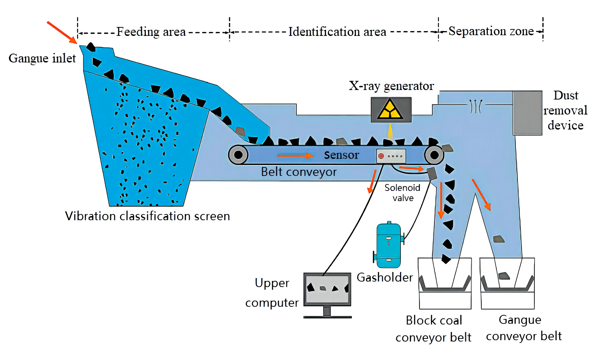
3. Key Technology of Underground Coal Gangue Photoelectric Separation

The key technologies of photoelectric separation of coal gangue include accurate identification of coal and gangue, efficient jet separation, and process layout in narrow space. In order to establish the precise identification mechanism of coal and gangue, it is necessary to analyze the absorption law of X-ray by different atoms and study the difference in the microscopic crystal characteristics of coal and gangue. In order to establish the low-energy and high-efficiency jet separation mechanism of coal and gangue, it is necessary to optimize the nozzle shape and parameters. Based on the mechanism of accurate identification and efficient injection separation of coal and gangue, the process layout of a coal gangue photoelectric separation system in narrow and long underground space should be explored.

3.1. Accurate Identification Mechanism of Coal and Gangue

Coal occurs in an amorphous way without a crystal structure, and gangue is mostly made of clay minerals, with an obvious crystal structure. According to this noticeable difference, the X-ray absorption fine structure (XAFS) method is used to identify the characteristic spectral lines of different gangue, and the absorption coefficient of target atoms to X-ray is obtained, so as to explore the difference law of coal gangue in terms of microscopic crystal properties, and then realize the accurate identification of coal gangue under X-ray [24].

3.1.1. Testing Plan

As shown in Figure 2, the crystal models of three commonly associated minerals in coal, montmorillonite, kaolinite, and α-quartz, were constructed. The characteristic spectra of the main atoms in XAFS spectra were analyzed using the method of multiple scattering calculation, and the difference in the characteristic spectra was used to identify coal and gangue.
The multiple scattering calculation method uses the web-atoms calculator to obtain the fitting parameters of effective cured wave scattering amplitude (FEFF), such as scattering amplitude, phase shift function, and mean free path. FEFF was used to simulate the crystal structure of the X-ray fine spectrum; polarization dependence, core–hole effects, and local field corrections were taken into account in the calculation. For different substances, the X-ray absorption coefficient graph can compare the changes in the X-ray absorption coefficient of different atoms at different energy sites.

3.1.2. Test Results and Discussion

The X-ray absorption coefficients of Al and Si atoms in α-quartz, montmorillonite, and kaolinite are shown in Figure 3. Figure 3a shows that the absorption coefficients μ(E) of Al atoms in kaolinite and montmorillonite are significantly different from each other. At E = 1570 eV, the Al atom of kaolinite has a characteristic peak, and at E = 1586 eV, there is a characteristic peak caused by an aluminum–oxygen structure. The Al atom in montmorillonite has a characteristic peak at E = 1567 eV and an absorption peak at E = 1584 eV, and the peak size is different. Therefore, the absorption peak of Al with different energies can be used as the basis to distinguish Al from kaolinite or montmorillonite.
It can be seen from Figure 3b that Si atoms in kaolinite, α-quartz, and montmorillonite have primary absorption peaks at E = 1845 eV, E = 1848 eV, and E = 1846 eV, and secondary absorption peaks at E = 1859 eV, E = 1861 eV, and E = 1859 eV, respectively. Among them, the Si atom in α-quartz has two absorption peaks of different intensities, which are, respectively, marked as Si0 and Si1. Therefore, the presence of the three minerals can be judged by the peak Si absorption.

3.2. Highly Efficient Jet Separation of Coal and Gangue

Accurately identified and positioned coal gangue will be hit by high-pressure airflow during the throwing process, thereby changing the movement trajectory of the gangue and achieving the separation of the target coal gangue. The shape and parameters of the nozzle have an essential impact on gas consumption and separation efficiency, and so the parameters of the nozzle need to be optimized.

3.2.1. Numerical Simulation and Optimization of Jet Nozzle Parameters

Geometric model: Four nozzles commonly used in coal gangue jet separation were selected, including flat nozzle, convergent nozzle (contraction angle was 15°), flat-convergent nozzle (contraction angle was 35°, contraction ratio was 1.6), and streamlined nozzle (contraction ratio was 1.6). The length of the nozzle was 20 mm, and the outlet diameter was 4 mm. (The nozzle contraction angle refers to the angle between two walls at the contraction section on the central axis section of the nozzle [25,26].)
Turbulence model and boundary conditions: Turbulence model and boundary conditions: Fluent software (Fluent 2021R1) was used to establish the model, and the reliable k-ε model was selected for the turbulence model. The inlet pressure was set at 0.2 MPa, the outlet pressure was atmospheric pressure, and the turbulence intensity was set at 2.9%.

3.2.2. Calculation Results and Discussion

The variation in nozzle jet velocity is shown in Figure 4. It can be seen from Figure 4 that the maximum speed achieved by the four types of nozzles is consistent. The jet core area of the flat-convergent nozzle is the shortest, while the jet core area of the other three nozzles is almost the same.
The comparison of the nozzle axis speed of different shapes is shown in Figure 5. It can be seen from Figure 5 that the jet velocity attenuation of the flat nozzle is the fastest, while that of the streamlined nozzle is the slowest.
In addition, the gas consumption per unit of time is also an important index of nozzle selection. The comparison of air consumption of nozzles with different shapes is shown in Figure 6. It is shown that the air consumption of the streamlined nozzle is the lowest.
According to the above results, the streamlined nozzle has a long effective range and the lowest gas consumption, and so it is an ideal choice for low-energy and high-efficiency jet nozzles.

3.3. Process Layout of Underground Coal Gangue Photoelectric Separation System

Based on the mechanism of precise identification of coal gangue and efficient jet separation, it is of great significance to explore the process layout of the photovoltaic separation system of coal gangue in a narrow and long space for realizing gangue source reduction.

3.3.1. Technical Characteristics of Coal Gangue Photoelectric Separation System Underground Layout

The coal gangue photoelectric separation system, which is arranged underground, needs to adapt to the narrow and long space and complex humid environment of underground. It should have the following technical characteristics: (1) Compact modular design. It should be arranged along the tunnel and make full use of the original chamber to reduce the excavation and support of the chamber. (2) Movable layout in conjunction with mining link. The photoelectric separation link is closely connected with the coal mining link, and the separation device is arranged behind the raw coal crusher, advancing synchronously with the mining system. (3) Realize the integration of mining, separation, and backfilling. With underground raw coal mining as the core, the underground mining, selection, and filling layout mode is constructed around the coal gangue sorting and coal gangue backfilling mode. (4) It should be in a multipoint scattered arrangement and realize a multiple parallel mode to multiply the processing capacity. (5) The separation system and raw coal conveying system work independently and do not affect the overall operation of the mining system. (6) It should meet the requirements of underground coal mine equipment in terms of shock absorption, heat dissipation, and being explosion-proof and anti-corrosive.

3.3.2. Technological Process of Underground Coal Gangue Photoelectric Separation System

A modular system was designed according to the technical requirements and characteristics of the downhole photoelectric separation system of coal gangue. The technological process of the underground coal gangue photoelectric separation system is shown in Figure 7. The system is mainly composed of three subsystems: raw coal mining, coal and gangue separation, and gangue backfilling. The raw coal mining subsystem includes a coal cutter, a belt of transshipment, and a coal haulage roadway, etc. The coal and gangue separation subsystem consists of material distribution, identification, and separation modules. The gangue backfilling subsystem is composed of a crusher, gangue bin, and filling mechanism.
The raw coal mined by the coal cutter is transported to the crusher through the coal haulage roadway and transported to the classification vibrating screen (screen hole size is 50 mm) after crushing to a particle size less than 300 mm. After grading, the undersize product (coal with particle size less than 50 mm) is transported to the downhole coal bunker through the transshipment belt, and then it is transported to the surface coal bunker through the central inclined shaft belt, or directly into the main coal flow system to lift to the surface bunker. The oversize product (coal with particle size greater than 50 mm) will be transported to the coal gangue photoelectric separator for sorting. The selected lump coal is transported to the lump coal bunker via the retractable belt conveyor, and then the lump coal is transported to the main inclined shaft belt for lifting to the surface bunker or directly into the main coal flow system to lift to the surface bunker. After the selected gangue is broken to a particle size below 100 mm, it is transported to the underground gangue bunker (or gangue storage site) via the belt conveyor and finally enters the filling working face.

4. Engineering Application of Underground Coal Gangue Photoelectric Separation System

4.1. Background of the Engineering Application

The engineering application base is preliminarily set in Renjiazhuang Coal Mine. The mine is located on the edge of the Mu Us Desert, 20 km northeast of Lingwu City, Ningxia Province, China. The mine adopts the mixed exploiting mode, and a total of three industrial sites are arranged. Three inclined shafts are placed in the site, namely, the main inclined shaft, vice inclined shaft, and return air inclined shaft. The coalfield is divided into three mining areas, whereby 11-mining area and 21-mining area are production mining areas, and 12-mining area is a preparatory mining area. The northern part of 21-mining area has a complex structure, a short advancing length of the working face, and a low production capacity. The 210503-working face of 21-mining area is close to the shaft station, the gangue transfer route is fast, and the cost is low; so, it is suitable to be used as the early filling mining working face. The third and fifth coal seams of 21-mining area were selected for work. The average thickness of the third coal seam was 3.34 m, and there was no gangue in the whole coal seam; the average thickness of the fifth coal seam was 6.03 m, and it was generally free of gangue. The approved production capacity of the mine is 3.6 million tons per year. According to the analysis of the raw coal screening data, coal with a particle size greater than 50 mm accounts for 7.79%. The capacity of gangue reduction is 222,500 tons per year.

4.2. Engineering Application Scheme

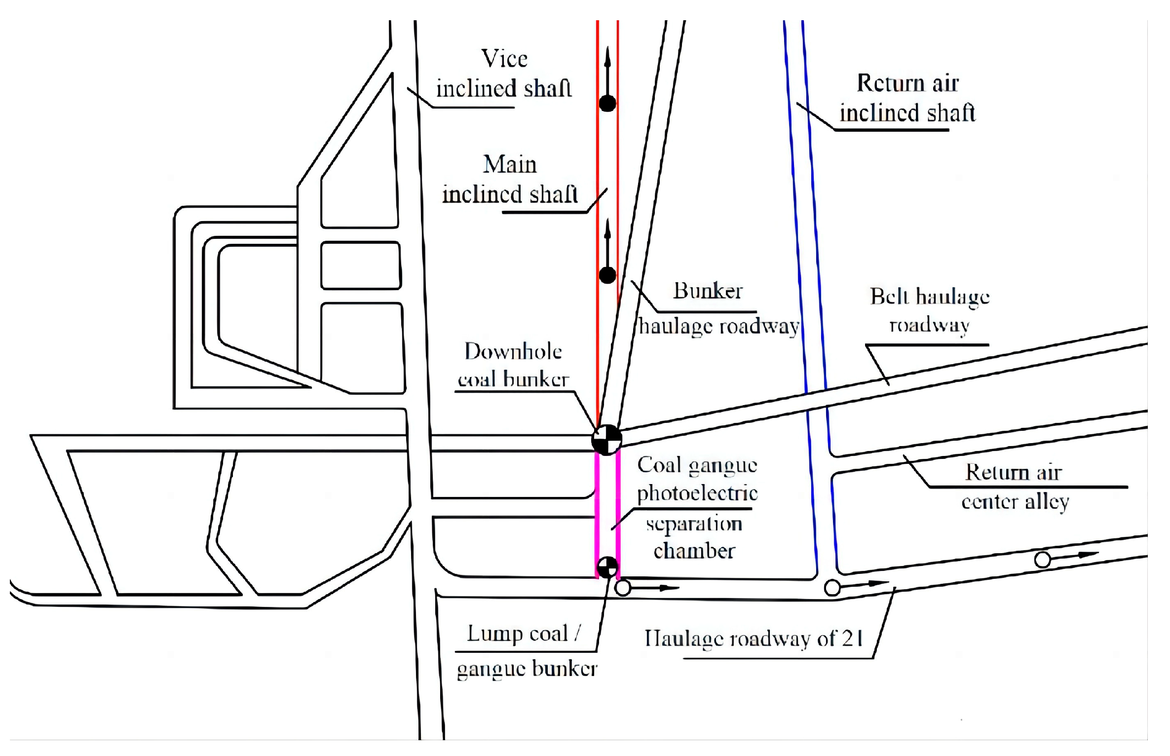
4.2.1. Centralized Layout Type

The haulage roadway distribution of the centralized layout is shown in Figure 8. The photoelectric separation system of the coal gangue is arranged at the upper entrance of the coal bunker in the shaft station. The coal transported by the bunker haulage roadway and the horizontal belt haulage roadway is sent to the crusher located at the entrance above the bunker. After the coal is crushed to a particle size of less than 300 mm, it is fed to the vibrating screen (screen hole size is 50 mm) below the crusher for classification. The undersized product (coal with particle size less than 50 mm) is sent into the downhole coal bunker for temporary storage, and then it is transported to the surface coal bunker through the main inclined shaft belt. The oversized product (coal with particle size greater than 50 mm) is sent into the underground coal gangue photoelectric separator to separate the lump coal and gangue, then transported into the lump coal bunker and gangue bunker, respectively, via the belt conveyor.
The bottom of the lump coal bunker is provided with an unloading opening, and the coal will be transported to the main inclined shaft belt through the lump coal transfer belt and then lifted to the surface bunker. A crusher is arranged at the upper entrance of the gangue bunker, and a loading gate is arranged at the bottom. After the gangue is broken to a particle size below 100 mm, it is transported from the haulage roadway of 21-mining area to the gangue storage and transfer chamber of the filling working face via a mining truck. The device distribution of the centralized layout is shown in Figure 9.

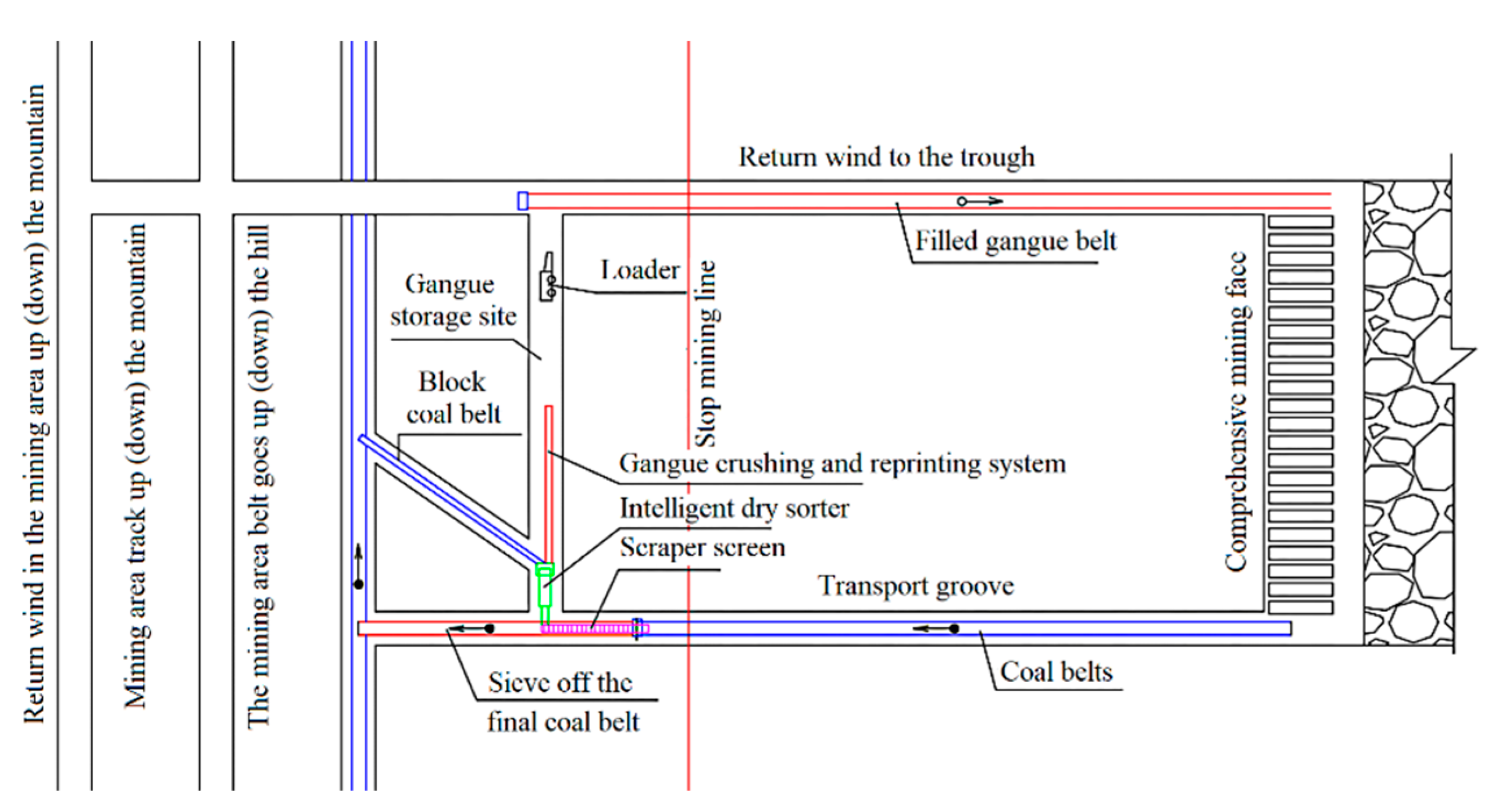
4.2.2. Distributed Layout Type

The haulage roadway distribution of the distributed layout is shown in Figure 10. The coal gangue photoelectric separation system is arranged at the head of the belt conveyor in the coal transport roadway of the 210503-working face. The head of the retractable belt conveyor is located near the stop line and connected to the scraper screen. After the raw coal is crushed to a particle size of less than 300 mm, it is transported to the scraper screen (screen hole size is 50 mm) via conveyor belt for classification.
The undersized product (coal with particle size less than 50 mm) is transported to the belt of the mining area through the vertically overlapped transshipment conveyor belt, and then it is fed into the main coal flow system. The oversized product (coal with a particle size greater than 50 mm) will be transported to the coal gangue photoelectric separator for sorting. After the selected gangue is broken to a particle size below 100 mm, it is transported to the underground gangue storage site and then transported via the transfer conveyor to the backfilling belt in the return air laneway for backfilling. The sorted lump coal is transported to the main coal flow system through the lump coal transfer belt and the mining belt and then lifted to the ground coal bunker. The device distribution of the distributed layout type is shown in Figure 11.

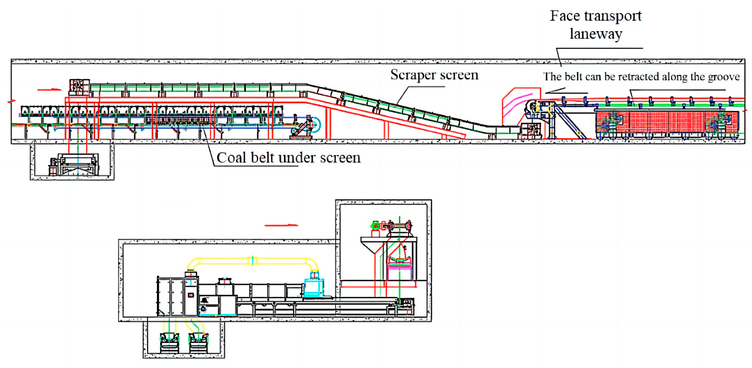
4.2.3. Mobile Layout Type

The haulage roadway distribution of the distributed layout type is shown in Figure 12. The coal gangue photoelectric separation system is designed as a vehicle-mounted type and arranged in the haulage roadway of the 210503-working face. The coal gangue photoelectric separator and its distribution room are arranged on one car board, and the air supply system is arranged on the second car board. The coal and gangue are transported via movable belt conveyor.
The three layout schemes of the underground coal gangue photoelectric separation system have their own advantages and disadvantages [4]. It can be selected according to the specific situation of the coal mine. The three layout types are shown in Table 2 in detail.

5. Conclusions

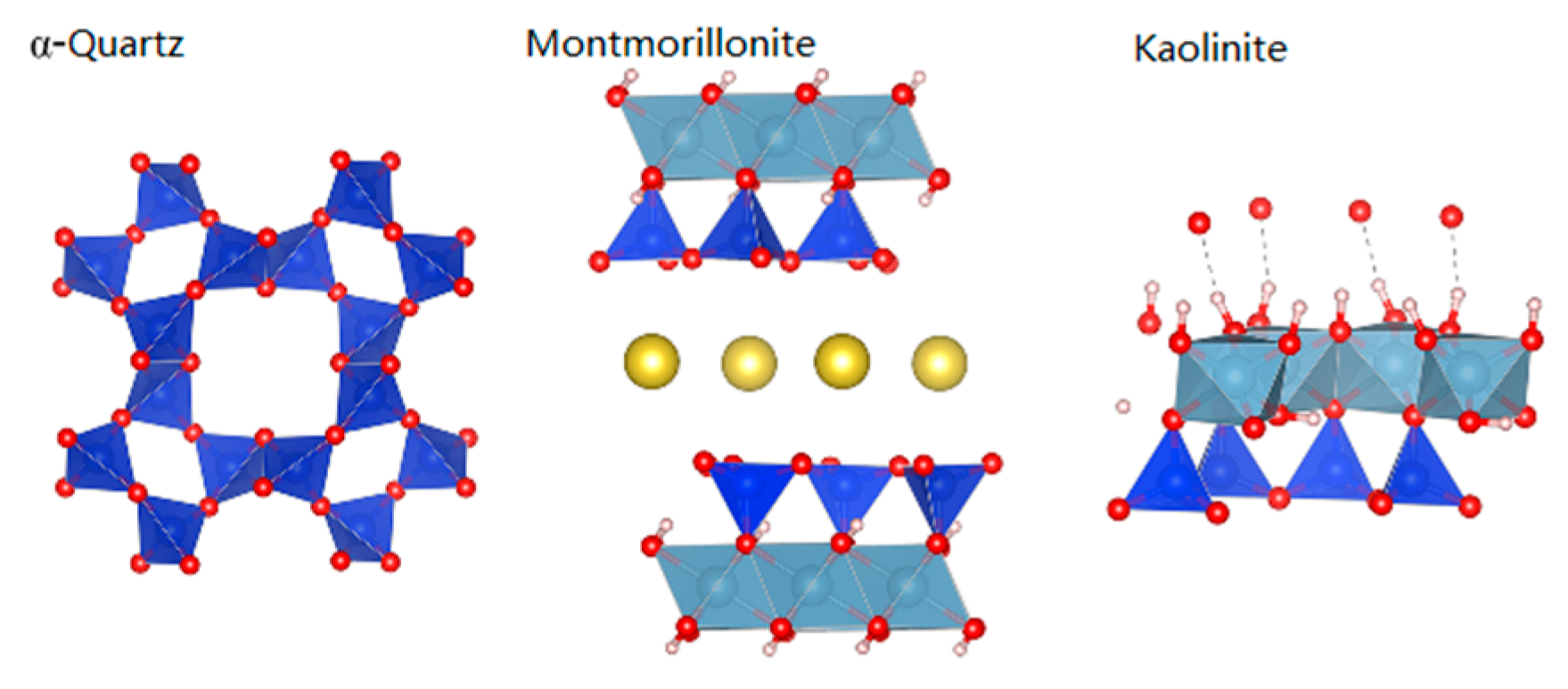
  • The characteristic spectral lines of montmorillonite, α-quartz, and kaolinite crystals are identified via the X-ray absorption fine structure (XAFS) method. The results show that the absorption coefficient μ(E) of Al and Si atoms in minerals is significantly different, and the XAFS method has the ability to identify different minerals, thus achieving accurate identification of coal and gangue under X-ray.
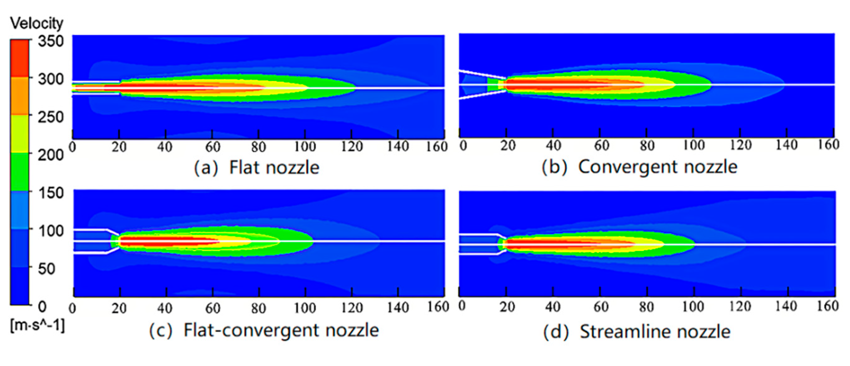
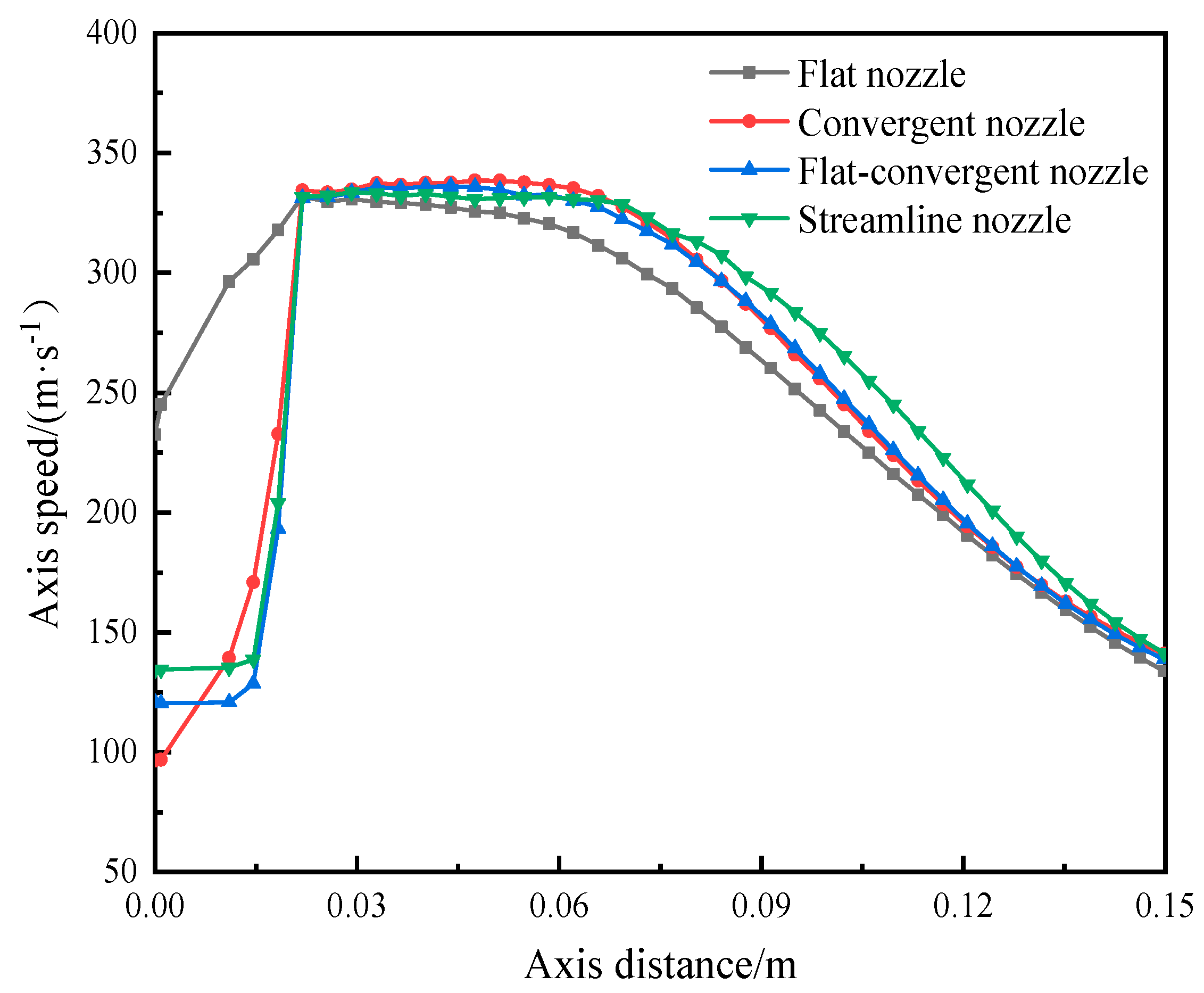
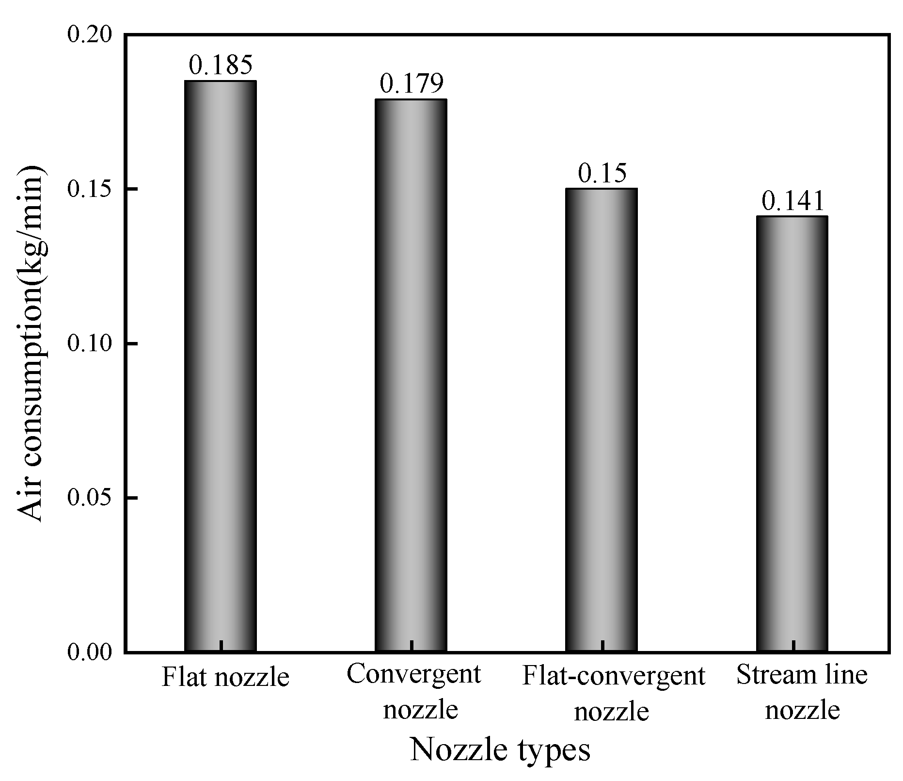
  • The numerical simulation results of four commonly used nozzles for coal gangue jet separation showed that the streamlined nozzle has the longest jet core area, the slowest jet velocity attenuation, and the lowest gas consumption per unit time, and its performance is better than the other three types of nozzles.
  • In this paper, the technical characteristics of the coal gangue photoelectric separation system are expounded, and the technological layout of the separation system is explored. Based on the exploiting and mining systems of Renjiazhuang Coal Mine, three layout types of the coal gangue photoelectric separation system are designed: centralized layout type, decentralized layout type, and mobile layout type, and the advantages and disadvantages of each type are obtained and compared.

Author Contributions

Conceptualization, W.Z. and J.Z.; methodology, W.Z.; software, W.X. and L.L. (Liangliang Liu); validation, W.X., L.L. (Liansheng Li) and Q.Z.; formal analysis, L.L. (Liangliang Liu); investigation, L.L. (Liansheng Li); resources, W.Z.; data curation, W.Z. and W.X.; writing—original draft preparation, W.X. and L.L. (Liangliang Liu); writing—review and editing, S.W. and W.X.; supervision, W.Z. and J.Z.; project administration, W.Z.; funding acquisition, W.Z. All authors have read and agreed to the published version of the manuscript.

Funding

This research is supported by the University Synergy Innovation Program of Anhui Province (GXXT-2022-016), the University Excellent Talents Training Funding Project of the Education Department of Anhui Province (gxyqZD2021109), the Natural Science Foundation of Anhui Province (2108085ME160), the Open Foundation of State Key Laboratory of Mining Response and Disaster Prevention and Control in Deep Coal Mines (SKLMRDPC19KF11), and the University Scientific Research Project of The Education Department of Anhui Province (KJ2021A0429).

Data Availability Statement

The data that support the findings of this study are available from the corresponding author upon reasonable request.

Acknowledgments

Special thanks to Jinbo Zhu of Anhui University of Science and Technology for his guidance in this study, and also to all those who participated in this study.

Conflicts of Interest

The authors declare no conflict of interest. The funders had no role in the design of the study; in the collection, analyses, or interpretation of data; in the writing of the manuscript; or in the decision to publish the results.

References

  1. Zhang, J.; Miao, X. Underground disposal of waste in coal mine. J. China Univ. Min. Technol. 2006, 35, 197–200. [Google Scholar]
  2. Zhang, K.; Li, J. The treatment of mine waste rock at underground. J. North China Inst. Sci. Technol. 2005, 2, 46–47. [Google Scholar]
  3. Zhang, J.; Ju, F.; Li, M.; Zhou, N.; Zhang, Q. Method of coal gangue separation and coordinated in-situ backfill mining. J. China Coal Soc. 2020, 45, 131–140. [Google Scholar]
  4. Zhang, J.; Tu, S.; Cao, Y.; Tan, Y.; Xi, H.; Pang, J. Coal gangue intelligent separation and backfilling technology and its engineering application in underground coal mine. J. China Univ. Min. Technol. 2021, 50, 417–430. [Google Scholar]
  5. Zhang, J.; Zhang, Q.; Ju, F.; Zhou, N.; Li, M.; Zhang, Q. Theory and technique of greening mining integrating mining, separating and backfilling in deep coal resources. J. China Coal Soc. 2018, 43, 377–389. [Google Scholar]
  6. He, Q. Research on Key Technique of the Integration of Separation and Backfilling in Coal Mining. Master’s Thesis, China University of Mining and Technology, Xuzhou, China, 2014. [Google Scholar]
  7. Zhang, H.; Zhang, Q.; Zuo, X.; Wu, Z.; Fan, W.; Liu, H.; Tian, X. Design and application of mining-separation-backfilling system for mining ecological and environmental protection. J. China Univ. Min. Technol. 2021, 50, 548–557. [Google Scholar]
  8. Dou, D.; Wu, W.; Yang, J.; Zhang, Y. Classification of coal and gangue under multiple surface conditions via machine vision and relief-SVM. Powder Technol. 2019, 356, 1024–1028. [Google Scholar] [CrossRef]
  9. Liu, Y.; Zhang, Z.; Liu, X.; Wang, L.; Xia, X. Performance evaluation of a deep learning based wet coal image classification. Miner. Eng. 2021, 171, 107126. [Google Scholar] [CrossRef]
  10. Hajialimohammadi, A.; Edgington-Mitchell, D.; Honnery, D.; Montazerin, N.; Abdullah, A.; Agha Mirsalim, M. Ultra high speed investigation of gaseous jet injected by a single-hole injector and proposing of an analytical method for pressure loss prediction during transient injection. Fuel 2016, 184, 100–109. [Google Scholar] [CrossRef]
  11. Wang, Y.; Wang, X.; Zhang, Z.; Li, Y.; Liu, H.; Zhang, X.; Hočevar, M. Optimization of a self-excited pulsed air-water jet nozzle based on the response surface methodology. Stroj. Vestn.-J. Mech. E 2021, 67, 75–87. [Google Scholar] [CrossRef]
  12. Cao, Y.; Liu, M.; Xing, Y.; Li, G.; Luo, J.; Gui, X. Current situation and prospect of underground coal preparation technology. J. Min. Saf. Eng. 2020, 37, 192–201. [Google Scholar]
  13. Deng, J.; Kuang, Y.; Zhao, J.; Sun, X.; Wang, C. Intelligent control strategy for the separation process of dense medium cyclone. J. China Univ. Min. Technol. 2019, 48, 624–632. [Google Scholar]
  14. Miao, X.; Zhang, J. Key technology of integration of coal mining-gangue washing-backfilling and coal mining. J. China Coal Soc. 2014, 39, 1424–1433. [Google Scholar]
  15. Zhou, C.; Liu, X.; Zhao, Y.; Yang, X.; Li, Y.; Dong, L.; Duan, C.; Rao, Z. Recent progress and potential challenges in coal upgrading via gravity dry separation technologies. Fuel 2021, 305, 121430. [Google Scholar] [CrossRef]
  16. Zhou, E.; Yan, G.; Weng, X.; Zhang, Z.; Zhao, P.; Zhang, B. A novel and low cost coal separation process: Combination of deep screening classification and gravity separation. Powder Technol. 2020, 367, 568–575. [Google Scholar] [CrossRef]
  17. Boylu, F.; Talı, E.; Çetinel, T.; Çelik, M.S. Effect of fluidizing characteristics on upgrading of lignitic coals in gravity based air jig. Int. J. Miner. Process. 2014, 129, 27–35. [Google Scholar] [CrossRef]
  18. Zhu, X.; Tao, Y.; Sun, Q.; Man, Z. The low efficiency of lignite separation by an enhanced gravity concentrator. Energy Sources Part A Recover. Util. Environ. Eff. 2017, 39, 835–842. [Google Scholar] [CrossRef]
  19. Zhang, Q.; Zhang, J.; Wu, Z.; Chen, Y. Overview of Solid Backfilling Technology Based on Coal-Waste Underground Separation in China. Sustainability 2019, 11, 2118. [Google Scholar] [CrossRef]
  20. Gülcan, E.; Gülsoy, Ö.Y. Performance evaluation of optical sorting in mineral processing—A case study with quartz, magnesite, hematite, lignite, copper and gold ores. Int. J. Miner. Process. 2017, 169, 129–141. [Google Scholar] [CrossRef]
  21. Zhang, Y.; Yoon, N.; Holuszko, M.E. Assessment of coal sortability and washability using dual energy X-ray transmission system. Int. J. Coal Prep. Util. 2022, 42, 2895–2907. [Google Scholar] [CrossRef]
  22. Zhang, Y.; Zhu, H.; Zhu, J.; Ou, Z.; Shen, T.; Sun, J.; Feng, A. Experimental study on separation of lumpish coal and gangue using X-ray. Energy Sources Part A Recover. Util. Environ. Eff. 2021, 1–13. [Google Scholar] [CrossRef]
  23. He, L.; Wang, S.; Guo, Y.; Hu, K.; Cheng, G.; Wang, X. Study of raw coal identification method by dual-energy X-ray and dual-view visible light imaging. Int. J. Coal Prep. Util. 2023, 43, 361–376. [Google Scholar] [CrossRef]
  24. Zeng, Q.Y.; Xie, J.; Zhou, W.; Zhu, J.B.; Liu, L.L.; Yin, J.Q.; Zhu, W.L. Study of the Crystallographic Distortion Mechanism during the Annealing of Kaolinite. Minerals 2022, 12, 994. [Google Scholar] [CrossRef]
  25. Liu, J. Optimization of Jet Pump Nozzle Shrinkage Angle. Master’s Thesis, Jiangsu University, Zhenjiang, China, 2013. [Google Scholar]
  26. Yan, L. Design and Test of Jet Separation Device in Plastic near Infrared Separation System. Master’s Thesis, Qingdao University of Science and Technology, Qingdao, China, 2018. [Google Scholar]
Figure 1. Schematic diagram of coal gangue photoelectric separation system.
Processes 11 02519 g001
Figure 2. Crystal structure of α-quartz, montmorillonite, and kaolinite.
Processes 11 02519 g002
Figure 3. The X-ray absorption coefficients of Al and Si atoms in α-quartz, montmorillonite, and kaolinite. (a) The absorption coefficient of Al atoms in kaolinite and montmorillonite; (b) the absorption coefficient of Si atoms in kaolinite, α-quartz, and montmorillonite.
Processes 11 02519 g003
Figure 4. Nozzle jet velocity variation.
Processes 11 02519 g004
Figure 5. Comparison of nozzle axis speed of different shapes.
Processes 11 02519 g005
Figure 6. Comparison of air consumption of different nozzle shapes.
Processes 11 02519 g006
Figure 7. Technological process of underground coal gangue photoelectric separation system.
Processes 11 02519 g007
Figure 8. Haulage roadway distribution of centralized layout type.
Processes 11 02519 g008
Figure 9. Device distribution of centralized layout type.
Processes 11 02519 g009
Figure 10. Haulage roadway distribution of distributed layout type.
Processes 11 02519 g010
Figure 11. Device distribution of distributed layout type.
Processes 11 02519 g011
Figure 12. Haulage roadway distribution of mobile layout type.
Processes 11 02519 g012
Table 1. Comparison of typical application cases of downhole gravity separation technology.
ProjectHeavy Medium Shallow Groove SeparationMoving Sieve Jigging SeparationAir Chamber Jigging Separation
Separation methodsWet separationWet separationWet separation
Feeding size/(mm)300–25300–25150–25
Processing capacity
of a single device
/(t/h)
30060–110280–380
Floor space/(m2)303635
Main equipmentClassifying screen, heavy medium shallow tank separator, crusher, medium drainage screen, magnetic separator, hydrocyclones, slime high-frequency screen, etc.Classifying screen,
moving jigger,
crusher,
pressure filter, etc.
Classifying screen,
air chamber underbed jig, crusher, etc.
LayoutChamberChamberChamber
Implementation siteJiyang Coal Mine of Shandong Xinwen Mining Group;
Xinjulong Coal Mine;
Zhaizhen Coal Mine
Xiezhuang Coal Mine of Shandong Xinwen Mining Group;
Linyi Coal Mine;
Tangshan Coal Mine of Kailuan Group
Xingdong Coal Mine of Jizhong Energy Group
Table 2. Comparison of three layout types of the coal gangue photoelectric separation system.
ItemsCentralized Layout TypeDistributed Layout TypeMobile Layout Type
PositionUpper entrance of the coal
bunker in the shaft station.
Near the stopping line in the working face haulage roadway.Haulage roadway
of working face.
Main
chamber
The underground coal bunker needs to be renovated. It is necessary to build a new coal gangue photoelectric separation chamber, a lump coal bunker, and a gangue bunker. Affects the normal production of the mine for about 1 month.Most of the transportation roadway needs to be repainted. New coal gangue photoelectric separation chamber and lump coal belt roadway need to be established. Does not affect normal production.Most of the transportation roadway needs to be repainted. New gangue bunker needs to be established. Does not affect normal production.
Merits
and demerits
(1) Good system operating environment and convenient maintenance of equipment.
(2) The gangue processing mode after selection is flexible, which can be filled after mining or directly in the haulage roadway.
(3) Gangue can be centrally treated.
(4) Long transportation lines and high costs.
(5) It is necessary to build a new chamber and transform the existing coal bunker.
(1) Poor operating environment.
(2) The gangue filling method is not flexible.
(3) Each working face needs to arrange a system, which has scattered management and low efficiency.
(4) Short transportation distance and low cost of gangue before and after treatment.
(5) It can make full use of coal seam roadway without building large chamber.
(1) Poor system operating environment.
(2) It is difficult to transfer and fill gangue.
(3) Modular design is required.
(4) The equipment can be moved, the gangue transportation line is short, and the cost is low.
(5) The system layout is difficult and the stability requirements are demanding.
Disclaimer/Publisher’s Note: The statements, opinions and data contained in all publications are solely those of the individual author(s) and contributor(s) and not of MDPI and/or the editor(s). MDPI and/or the editor(s) disclaim responsibility for any injury to people or property resulting from any ideas, methods, instructions or products referred to in the content.

