Review

Review of Recent Advances in the Drive Method of Hydraulic Control Valve

1
College of Mechanical and Electronic Engineering, Shandong University of Science and Technology, Qingdao 266590, China
2
College of Mechanical Engineering, Qilu University of Technology, Jinan 250353, China
3
College of Transportation, Shandong University of Science and Technology, Qingdao 266590, China
*
Author to whom correspondence should be addressed.
Processes 2023, 11(9), 2537; https://doi.org/10.3390/pr11092537
Submission received: 22 July 2023 / Revised: 18 August 2023 / Accepted: 22 August 2023 / Published: 24 August 2023

Abstract

:
Hydraulic control valves are widely used in industrial production, agricultural equipment, construction machinery, and other large power equipment for controlling the pressure and flow of fluids in hydraulic systems. The driving method has a significant impact on the response and control accuracy of hydraulic valves. This paper reviews the driving methods of spools from five aspects: solenoid drive, material expansion drive, motor drive, hydraulic valve drive, and another drive. It summarizes the various schemes currently available for spool drive and analyzes each of them. After optimizing the driving method of the valve core, the control accuracy can reach 3%, and the minimum response time is 7 ms. According to the characteristics of the different drive methods, the differences between them are compared, the advantages and disadvantages of each drive method are analyzed, and the application scenarios for each drive method are identified. Solutions to the drawbacks of the existing drive methods are proposed, which provide directions for further optimization. We have found that solenoid drives are simple to control, low cost, and the most widely used. Material telescopic drives, motor drives, hydraulic valve drives, and other drives are costly, complex to control, and optional for use in special requirement situations. Based on the existing spool drive methods, an outlook on future drive methods is presented. This review facilitates a comprehensive understanding of the drive methods of hydraulic valve spools, points out the shortcomings of the existing drive methods, and is of great significance in improving the existing drive methods and proposing new drive methods. This paper has a positive effect on improving the control accuracy and responsiveness of hydraulic valves.

1. Introduction

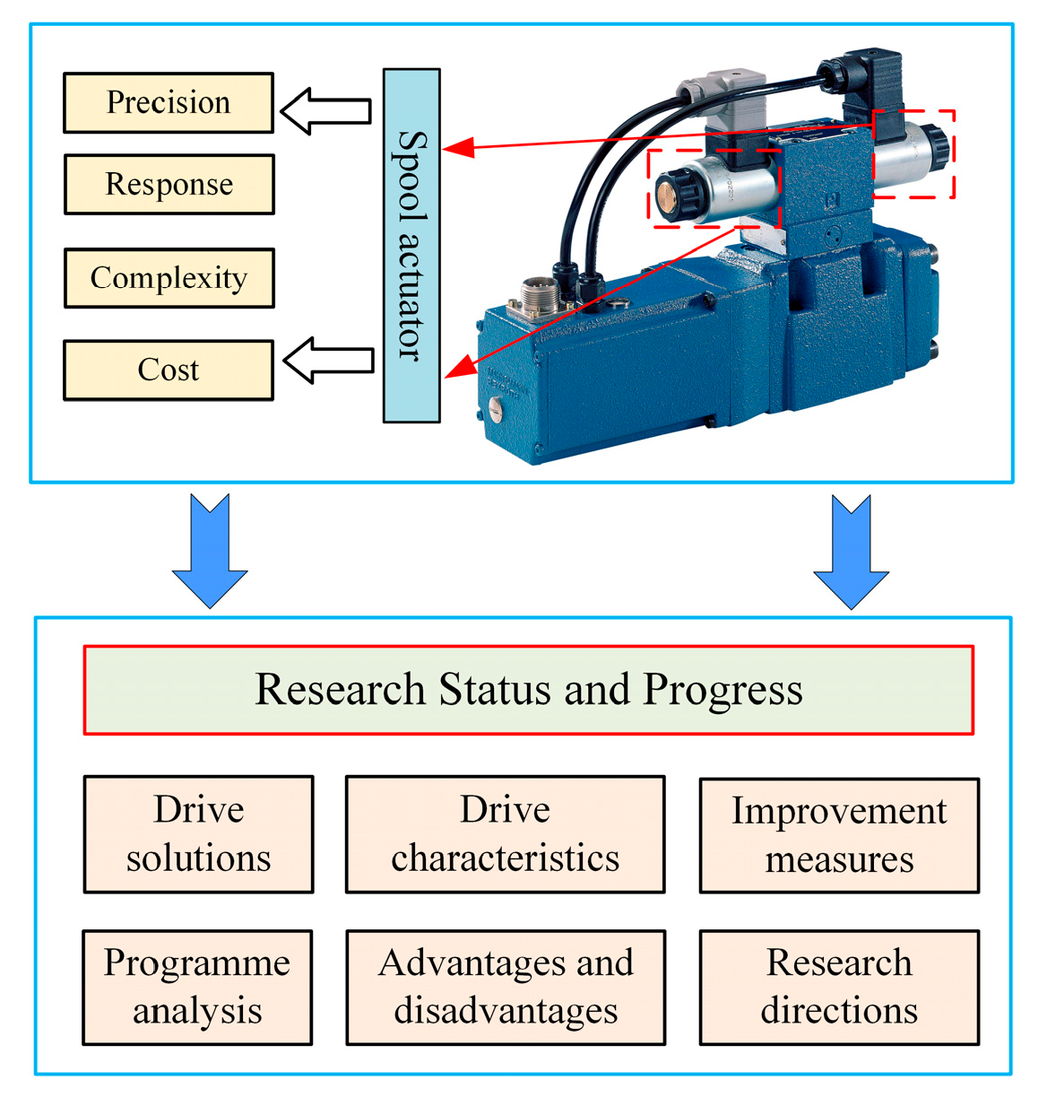
The hydraulic control valve is a hydraulic component with a high power density and large force output which is widely used in large power platforms and high-end intelligent equipment [1,2]. The control elements of the valve mainly include directional control valves, flow control valves, and pressure control valves. The spool of the hydraulic control valves is divided into direct drive and pilot drive. Direct-operated hydraulic control valves [3] drive the main spool movement directly through an external actuator, while pilot-operated hydraulic control valves [4] drive the main spool movement indirectly through a pilot stage. Direct-operated hydraulic valves require a large driving force which is highly responsive and requires low cleanliness of the hydraulic fluid. Pilot-operated hydraulic valves require a small driving force due to the amplification links. Pilot-operated hydraulic valves have many transmission links, so they have poor responsiveness and require a high level of cleanliness of the hydraulic fluid. Direct-operated and pilot-operated hydraulic control valves are shown in Figure 1.
Hydraulic control valves are used to change the size of the valve orifice by driving the spool movement, thus changing the pressure and flow rate of the hydraulic system. The commonly used spool drive element is an electrical–mechanical converter, which converts an electrical signal into spool displacement [5]. The choice of drive element directly affects the quality of the spool drive and relates to the performance of the entire hydraulic system. In traditional hydraulic control valves, solenoids are often used to drive spools. However, solenoid drives cannot meet the requirements of high precision and high response [6]. The electromagnet driving method has the characteristics of a simple structure and convenient control, but the electromagnet is prone to heating during operation and has a small driving force. The traditional electromagnetic drive is suitable for direct-operated hydraulic valves with a low driving force and pilot-operated hydraulic valves. Therefore, researchers have developed a variety of spool drive methods, such as stepper motors [7], torque motors [8], voice coil motors (VCMs) [9], permanent magnet synchronous motors [10], and piezoelectric stacked actuators [11]. The stepper motor and permanent magnet synchronous motor are in rotational motion. When the rotary motor drives the linear motion of the valve core, it is necessary to add a motion conversion link to convert the rotary motion into linear motion. The torque motor and voice coil motor can directly drive the linear movement of the valve core. The piezoelectric stacked actuators have a simple structure and high driving force, but a small displacement. From the perspectives of actuator structure, drive performance, control difficulty, and cost, researchers in various countries have proposed different spool drive solutions. The differences in application and drive performance between the different drive methods will be described in the following sections.
Previous researchers have only studied a single drive mode and have not studied and analyzed different drive modes, and users cannot choose the appropriate spool drive according to their needs. To select a suitable spool drive method, this paper reviews the research status and progress. By analyzing different drive modes, it provides a reference for users to choose the appropriate drive mode in terms of both control accuracy and responsiveness of the hydraulic valves. Among the traditional solenoid drive schemes, two aspects are summarized: single solenoid drive and double solenoid drive. In addition to the traditional drive methods, four other drive methods are summarized: material expansion drive, motor drive, hydraulic valve drive, and other drives. The characteristics of the different drive methods are analyzed and the application scenarios for each are identified. The advantages and disadvantages of the different drive methods are analyzed and solutions are proposed for the disadvantages. Finally, a summary of the various drive methods and an outlook on future spool drive methods are presented. The review contents are shown in Figure 2. This article elaborates on the driving methods of the valve core from different aspects, analyzes the control accuracy and responsiveness of the hydraulic valve from the driving methods, and provides a foundation for optimizing the driving performance and control strategy of the electromechanical converter, which is conducive to further improving the driving performance of the valve core. The impact of electromechanical converters on the performance of hydraulic valves has not been comprehensively and deeply analyzed by previous researchers, so this review has novelty. This paper analyzes the control accuracy and responsiveness of hydraulic valves in terms of the spool actuation method, which contributes to the improvement of the dynamic and static performance of the hydraulic system.

2. Solenoid Drive

Among the spool drive types of hydraulic valves, solenoid drives are the most common drive method. Solenoids have the characteristics of a simple structure, high reliability, and low cost [12]. The types of electromagnets are divided into DC electromagnets and AC electromagnets. Generally, hydraulic valve controllers output direct current, so direct current electromagnets are widely used. Electromagnets are also divided into pull-type and push-type, with push-type being the most used in practical applications. Solenoid drives are divided into single solenoid drives and double solenoid drives. In the single solenoid drive method, one solenoid is used to drive the spool, and the spool is returned to its initial position using a return spring. In the double solenoid drive method, two solenoids are used to drive the spool and it also uses a return spring to drive the spool back to its initial position.

2.1. Single Solenoid Drive

In direct-operated control valves, Dülk I et al. [13,14] used one proportional solenoid to drive the spool of a proportional flow valve and controlled the flow by varying the current of the proportional solenoid. Wu W et al. [15,16] used one proportional solenoid to drive a direct-operated proportional pressure regulating valve and controlled the pressure by varying the current of the proportional solenoid. Chen CP and Chiang MH [17] also used one proportional solenoid to drive a direct-operated proportional pressure regulating valve, but unlike Wu W et al. they controlled the pressure by varying the voltage of the proportional solenoid. Ferrari A et al. [18] studied a proportional solenoid-driven direct-operated servo-proportional flow directional valve. The proportional solenoid was connected to the valve spool and a PWM (pulse width modulation) current square wave signal was input to the proportional solenoid. The displacement of the spool was regulated by varying the duty cycle of the PWM signal. Mahajan P et al. [19] proposed to use a proportional solenoid to drive the spool of a direct-operated switching solenoid valve. A PWM voltage signal was input to the proportional solenoid and the spool movement was controlled by varying the duty cycle of the PWM signal. Ledvon M et al. [20,21,22,23] used a proportional solenoid to drive the spool of a direct-operated proportional directional valve. The direction of spool movement was changed by varying the voltage direction of the proportional solenoid, thus changing the direction of fluid flow, as shown in Figure 3. Bosch Rexroth’s 4WRPEH6 proportional directional valve also uses the same drive method [24]. Gamble JB et al. [25,26,27] used a proportional solenoid to drive the spool of a direct-operated proportional solenoid valve. The characteristics of the proportional solenoid were investigated [28] and the pressure and flow of the proportional solenoid valve were regulated by controlling the displacement of the spool. Lin YQ and Shi HQ [29] proposed a new proportional solenoid structure, which improved the armature structure of the proportional solenoid. The proportional solenoid was connected to the spool, and the movement of the spool was controlled by controlling the input signal of the proportional solenoid. Meng F et al. [30,31,32,33] proposed using a proportional solenoid to drive the movement of the ball valve spool. In the initial state, the valve orifice was open. When the inlet pressure increased, the valve orifice closed. The output force of the proportional solenoid could be adjusted to drive the ball spool movement and, thus, control the opening of the valve orifice.
In direct-operated control valves, in addition to conventional proportional solenoid drive, there are switching solenoids and bi-directional proportional solenoids. Tian H and Zhao Y [34] used a switching solenoid to control the conduction and closure of a direct-operated solenoid switching valve. Hao YX et al. [35] used a bi-directional proportional solenoid to drive a direct-operated proportional valve. The bi-directional solenoid contains two excitation coils; when one coil is energized, the solenoid generates driving force in one direction, and when the other coil is energized, the solenoid generates driving force in the other direction. During operation, only one of the two coils is energized. The bi-directional proportional solenoid controls the magnitude and direction of spool displacement by selecting the coil to be excited and controlling the voltage amplitude. Yuan YF et al. [36,37] used a bi-directional proportional solenoid to drive a pneumatically controlled hydraulic valve. The performance of the bi-directional solenoid was investigated and its output performance was optimized. Li QP et al. [38] studied a bi-directional proportional electro-mechanical converter with permanent magnets for electro-hydraulic proportional valves and servo valves. Based on a common solenoid, this bi-directional proportional electro-mechanical converter adds a ring-shaped permanent magnet, which controls the magnitude and direction of the output force by controlling the direction and amplitude of the current in the solenoid coil.
In the spool drive of the pilot valve, Carpenter R et al. [39,40] use a proportional solenoid to drive the pilot spool. The main spool is connected to the pilot valve at one end and to the return port at the other. When the solenoid is not energized, the port of the pilot valve is closed. As the pressure from the pilot valve cannot be transferred to the control chamber of the main spool, the pressure at both ends of the main spool is equal and the port of the main spool is closed. When the solenoid is energized, the solenoid generates a driving force to move the pilot spool. When the pilot valve opens, the pressure at one end of the main spool connected to the pilot stage increases. When the pressure at both ends of the main spool is unbalanced, the port of the main spool is opened. The higher the current of the solenoid, the greater the opening of the main spool’s ports. Fan XW et al. [41,42] used a proportional solenoid to drive a pilot-operated pressure-regulating solenoid valve and a pilot-operated pressure-reducing valve. They regulate the pressure of the hydraulic valve by varying the current of the proportional solenoid [43]. Quan L et al. [44] proposed a pilot-operated proportional directional valve based on internal flow feedback. The pilot-operated proportional valve is driven by a bi-directional solenoid, which is connected to the spool of the pilot valve. The bi-directional electromagnet drives the pilot valve core to move, changing the pressure difference between the two ends of the main valve core. When the pressure difference between the two ends of the main valve core is large enough, it can drive the main valve core to move. Zuo Q et al. [45] used a proportional solenoid to drive a two-dimensional (2D) proportional directional valve. A compression–torsion coupling connects the proportional solenoid to the spool and converts the linear motion of the proportional solenoid into the linear and rotary motion of the spool. When the driving force of the proportional solenoid is reduced, the spool is restored to its initial position by means of a reset spring. Ye QF et al. [46,47,48,49,50] proposed a solenoid-driven pilot-operated proportional solenoid valve. One end of the main spool is connected to the inlet pressure through an orifice and the other end is connected to the outlet pressure. The two ends of the main spool are connected via a pilot cone valve. The opening of the cone valve is adjusted by controlling the proportional solenoid, thus changing the differential pressure at both ends of the main spool, and finally realizing the drive of the main spool. Wang H et al. [51,52,53,54,55] proposed a pilot-operated proportional flow valve driven by a proportional solenoid. Unlike Ye QF et al., they used a proportional valve to control the displacement of the main spool. The inlet of the pilot valve was connected to one end of the main spool, and the outlet of the pilot valve was connected to the other end of the main spool. When the proportional solenoid drove the pilot spool movement, it changed the inlet and outlet pressures, i.e., it changed the differential pressure between the two ends of the main spool and realized the main spool drive. The two types of drive for pilot-operated proportional valves are shown in Figure 4. D’Amore M and Pellegrinetti G [56] introduced a bi-directional solenoid-driven nozzle–flapper servo valve. The bi-directional solenoid valve was connected to the baffle, and the nozzles on both sides of the baffle were connected to the control chambers at both ends of the main valve core. When the bi-directional solenoid valve drove the baffle to move, it changed the distance between the baffle and the nozzle, and drove the movement of the valve core by changing the pressure difference at both ends of the main valve core.
When a single solenoid is used to drive the spool, it generally has only unidirectional drive capability. When a bi-directional solenoid is used, the spool can move in two directions. The bi-directional solenoid has two drive coils, only one of which is energized during operation. In single solenoid drives, proportional solenoids are often used to drive the spool. Because proportional solenoids control the output force by varying the voltage or current, they can control the spool movement continuously and proportionally. Switching solenoids are generally used in switching valves. When the solenoid is energized, the valve port of the hydraulic valve is opened; when the solenoid is not energized, the valve port of the hydraulic valve is closed. With a single solenoid drive, the main and pilot spools of the flow, pressure, and directional valves can be driven. When the solenoid drives a hydraulic valve of the same performance, a smaller driving force is required to drive the pilot spool, but a larger driving force is required to drive the main spool. Due to the magnetic saturation of the solenoid, the output drive force is limited. Therefore, when the main spool requires a small driving force, the solenoid is used to drive the main spool directly. When the main spool requires a larger driving force, a pilot control is used to drive the main spool indirectly. When the solenoid is directly connected to the spool, the spool movement can only be driven linearly. To enable the solenoid to drive the spool of a 2D hydraulic valve, a compression–torsion coupling is used to convert the linear motion into a rotary motion.

2.2. Double Solenoid Drive

Among direct-operated control valves, Lisowski E et al. [57] studied segmented proportional directional valves, where the entire hydraulic valve consists of three direct-operated proportional directional valves. Each direct-operated proportional directional valve uses two proportional solenoids to drive the spool, thus changing the direction of the fluid flow [58]. Amirante R et al. [59] introduced the 4/3 ATOS DKZOR-T proportional directional valve. This proportional directional valve has an integrated electronic driver which sends commands to the proportional solenoids at both ends of the control spool, thus driving the spool movement. Tic V et al. [60] introduced a direct-operated proportional directional valve with double proportional solenoid actuation without displacement feedback. The spool movement is driven by controlling the current of the two proportional solenoids, thereby controlling the direction of flow and fluid. Jin B et al. [61,62,63,64] studied a directly operated proportional directional valve with displacement feedback. The spool position is detected using a displacement sensor and the spool is driven by adjusting the current of two proportional solenoids using a closed-loop differential control method. Owczarek P et al. [65,66] studied electro-hydraulic proportional flow valves with displacement feedback. They used two proportional solenoids to drive the spool movement and, thus, vary the output flow rate. Although Bayat F et al. [67] also used two proportional solenoids to drive the spool of a proportional valve, the outputs of both proportional solenoids were not directly connected to the spool. One of the proportional solenoids was connected directly to one end of the spool, and the other was connected to the other end of the spool via a force sensor. By controlling the input signals of the two proportional solenoids, it was possible not only to drive the spool movement but also to detect the amount of force applied to the spool.
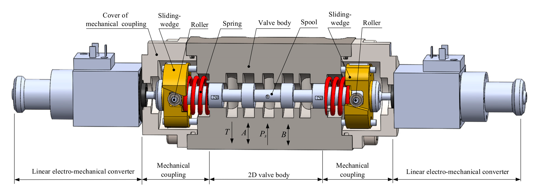
In pilot-operated control valves, Zavarehi M K et al. [68] used two proportional solenoids to control pilot-operated electro-hydraulic servo valves. By controlling the input signal to the pilot stage proportional solenoids, the driving force at both ends of the pilot spool is changed. When the difference in driving force between the two ends reaches a certain value, the pilot spool starts to move, changing the pressure and fluid flow direction of the pilot valve. The two ends of the pilot valve are connected to the two ends of the main spool. The change in pressure at the two ends of the pilot valve causes a change in pressure at the two ends of the main spool, which drives the movement of the main spool. Several Bosch Rexroth pilot-operated proportional directional valves are driven by double solenoids which regulate the movement of the spool by controlling the current of the proportional solenoids at both ends of the spool, thus changing the direction of fluid flow [69,70]. Saleem S [71] introduced the pilot-operated flow directional control valve. The difference in output force between the two proportional solenoids can drive the movement of the pilot spool, which in turn changes the differential pressure between the two ends of the main spool and enables the main spool to be driven. The movement of the main spool changes the opening of the valve orifice and achieves a change in the flow and direction of the fluid. To achieve precise control of the pilot-operated flow directional valve, Xu B et al. [72,73,74,75,76] also used two proportional solenoids to drive the pilot-operated flow directional valve, adding an LVDT (linear variable displacement transducer) to detect the displacement of the main spool to achieve closed-loop control. By optimizing the input signals of the two proportional solenoids, the control dead zone of the proportional directional valve was reduced. Meng B et al. [77] used two proportional solenoids to drive the spool of a 2D electro-hydraulic proportional directional valve. A thrust–twist coupling connected the proportional solenoids to the spool and converted the axial linear motion of the proportional solenoids into an axial linear and rotational motion of the spool. During control, the displacement of the spool was adjusted by varying the current of the two proportional solenoids. The 2D electro-hydraulic proportional directional valve with the double solenoid drive is shown in Figure 5.
The double solenoid drive is generally used in proportional directional valves, where the use of two solenoids allows the spool to move in both directions, thus enabling the direction of fluid flow in the directional valve to be changed. In addition to proportional directional valves, double solenoids can also be used for proportional flow valves. In the double solenoid drive method, a proportional solenoid is used to drive the spool, allowing for proportional adjustment of the spool. To accurately control the spool position, a displacement sensor is usually installed at one end of the spool to detect the spool displacement, which is then transmitted to the controller for closed-loop control.
The summary of the solenoid-driven spool is shown in Table 1.
As can be seen from Table 1, the proportional solenoid is the most commonly used of the solenoid drive methods. For cost saving and ease of control, the single solenoid drive is generally used. However, the directional valve spool requires a bi-directional drive and, therefore, a double solenoid drive or a single bi-directional solenoid drive is required. In the drive method, the direct drive of the spool is preferred to reduce the transmission link. When the driving force cannot be met, the pilot drive method is chosen. In the control method, voltage control and current control can be selected according to requirements. In practice, a voltage signal is generally used to drive the solenoid and the sampling circuit is used to obtain the solenoid current, thus controlling the force and displacement of the solenoid output.
In general, single or double solenoids can drive the spool. Due to the magnetic saturation phenomenon, the drive capacity of the solenoid is limited. When the spool requires a small drive force, the direct drive of the spool is sufficient. When the spool requires a larger driving force, the proportional solenoid is unable to drive the spool directly and the driving force can be amplified using pilot control technology. In terms of solenoid control, the control is simple, and the output force can be controlled by varying the voltage or current. However, the solenoid has a drive dead zone and hysteresis loop, which should be minimized. Due to the small clearance between the spool and the valve body, the solenoid drive method may have problems with the spool jamming.

3. Material Expansion Drive

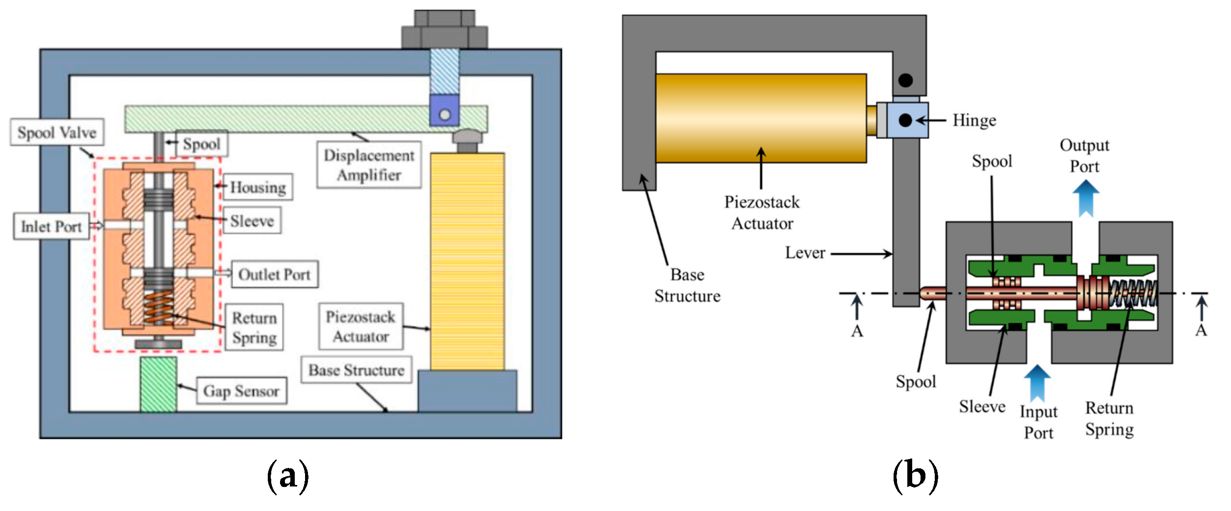
The material expansion drive method is to apply a voltage signal to the material and the voltage excitation causes a displacement movement of the material to drive the spool movement. Angelov I et al. [78] introduced a B-type proportional valve with mechanical amplification and piezoelectric control. The flexible beam mechanism is connected to the output shaft of the piezoelectric stacking actuator at one end and to the spool at the other. If the A end of the flexible beam mechanism is connected to the output shaft of the piezoelectric stack actuator, the B end is connected to the valve spool. If the A end of the flexible beam mechanism is connected to the output shaft of the piezoelectric stack actuator, the B end is connected to the valve spool. When the output shaft of the piezoelectric stack actuator moves, it drives the A end of the flexible beam mechanism to produce a small displacement and the B end of the flexible beam mechanism to produce a larger displacement, realizing the drive of the spool. They also proposed a pilot-operated proportional valve driven by a double piezoelectric stack actuator. Two piezoelectric stack actuators control the pilot stages of the proportional valve and the pressure of the two pilot stages is connected to the pressure at the ends of the main spool. The piezoelectric stack actuator changes the pressure in the pilot stage, which in turn changes the pressure at both ends of the main spool, enabling the main spool to be driven. Han C et al. [6,11] also proposed a similar actuation scheme. Yu-Park YJ et al. [79] proposed a piezoelectric stack actuator based on a valve system, which works on the same principle as a B-type proportional valve, but there are differences in the drive method. In the B-type proportional valve, the output shaft of the piezoelectric stack actuator pulls the spool movement through a lever; in the valve-system-based piezoelectric stack actuator, the piezoelectric stack actuator pushes the spool movement through a lever. The principle of the piezoelectric stack actuator push/pull spool is shown in Figure 6, the left-hand panel shows the push spool movement and the right-hand panel shows the pull spool movement. Zhang ZM et al. [80] proposed a throttling control valve directly driven by a piezoelectric stack actuator. Assuming that the ends of the valve seat actuator are A and B, and the ends of the ball spool are C and D. The output shaft of the piezoelectric stack actuator is connected to A of the valve seat actuator, B of the valve seat actuator is connected to C of the ball spool, and D of the ball spool is connected to the spring. When the voltage of the piezoelectric stack actuator increases, it pushes the ball spool to move and the opening of the valve port increases. When the voltage of the piezoelectric stack actuator decreases, the spring pushes the ball spool and the valve opening decreases. Therefore, the valve opening can be adjusted by controlling the voltage of the piezoelectric stack actuator. Stefanski F et al. [81] used a piezoelectric ring bender to drive spools. When the direction and amplitude of the applied voltage are different, the bending direction and size of the piezoelectric ring bender are different. The piezoelectric ring bender is directly connected to the spool and can drive the spool in two directions by changing the direction and magnitude of the voltage.
Murrenhoff H [82] proposed a pilot-operated piezoelectric valve. Two piezoelectric stacked actuators are connected to the flapper and the nozzle is connected to both ends of the spool. When the voltage of the piezoelectric stack actuator increases, the distance between the flapper and the nozzle decreases and the pressure on the spool increases. When the voltage of the piezoelectric stack actuator decreases, the distance between the flapper and the nozzle increases and the pressure of the spool decreases. By adjusting the voltage of the two piezoelectric stack actuators, the spool can be driven. Tamburrano P et al. [83] studied a nozzle–flapper servo valve driven by a piezoelectric ring bender actuator. The conventional driving method is a torque motor drive flapper, while this solution uses a piezoelectric ring bender to drive the flapper. When the voltage of the piezoelectric ring bender increases, it drives the flapper to move, changing the distance between the flapper and the nozzle, thus changing the pressure difference between the two ends of the spool and realizing the spool drive. Sangiah DK et al. [84] changed the torque motor of the baffle–nozzle servo valve to a bimorph actuator that could drive the spool in two directions. Wang XH et al. [85] also improved the conventional nozzle–flapper servo valve by replacing the torque motor with a magnetostrictive actuator. There are disc springs on both sides of the flapper. The disc springs are connected to a micro-displacement amplifier, which is connected to the magnetostrictive actuator. When the magnetostrictive actuator produces a small displacement, the displacement is amplified by the micro-displacement amplifier, which drives the disc spring to output displacement and force. When the forces on both sides of the flapper are uneven, this will displace the flapper, thus changing the distance between the flapper and the nozzle and realizing the drive of the spool.
The summary of the material expansion drive is shown in Table 2.
As can be seen in Table 2, the most commonly used actuator is the piezoelectric stacked actuator, while some drives use magnetostrictive actuators as well. Since the displacement of the expansion material is positively related to the input signal, the displacement can be controlled proportionally by adjusting the input signal, so the material expansion drive method is often used to drive the spool of the proportional valve. The displacement of the expansion material is generally very small and can drive a small displacement of the spool. In general, it is necessary to add displacement amplifiers or use pilot control to convert small displacements into large displacements. Piezoelectric stacks actuators and magnetostrictive actuators can only drive in one direction, while piezoelectric ring benders and bimorph actuators can drive in two directions. In practical applications, the appropriate spool drive actuator should be selected based on the drive performance requirements and cost.
Since material expansion uses the tension of the material to achieve high energy conversion and effectiveness, this drive method has better responsiveness and displacement resolution. The material expansion drive method utilizes the properties of the material itself and does not require the addition of other energy conversion components, resulting in a simple structure, small size, and less heat generation. Compared with the conventional solenoid drive, there is no electromagnetic noise. However, the displacement of material expansion is small, which can only meet the micro-displacement motion of the spool and cannot meet the general spool motion requirements. To meet the large stroke displacement requirements of the spool, on one hand, multiple pieces of expansion materials are stacked together so that multiple small displacements can be synthesized into large displacements, but this method will increase the volume of the actuator. On the other hand, the small displacements are amplified by a displacement amplification device, but this method will increase the mechanical transmission link and reduce the drive efficiency. In practice, the appropriate displacement amplification method is selected according to the drive performance requirements.

4. Motor Drive

Motor drives include stepper motors, torque motors, voice coil motors, and other new types of motors. To meet the driving requirements of hydraulic valves, electromagnetic simulation software is used to analyze the internal structure of the motor, and parameterization methods are used to optimize the motor structure. The different types of motor drives are described below.

4.1. Stepper Motor Drive

Amirante R et al. [3] introduced the use of a stepper motor to drive the spool of a direct-operated proportional valve. A ball screw connects the output shaft of the stepper motor to the spool and converts the rotational motion of the motor to the linear motion of the spool. Zhou RL et al. [86] also used a stepper motor to drive the spool motion, but the drive mechanism was different. The output shaft of the stepper motor is rigidly connected to one end of the spool through a coupling, and the other end of the spool is rigidly connected to a screw, which is connected to a fixed nut. The rotation of the stepper motor drives the rotation of the spool and the screw, which results in the axial movement of the spool. Fu YL and Zhou GZ [87] proposed the use of a two-stage screw internal feedback digital actuator instead of a servo valve, and the stepper motor was connected to the spool by sliding keys and threads [88] for stepper motor drive spool motion. Rybarczyk D [89] proposed the use of stepper motors and DC (direct current) motors to drive the spool of a direct-operated proportional valve. The stepper motor output shaft is connected to the spool through a coupling, and the spool is rigidly connected to the screw. The DC motor output shaft is rigidly connected to the nut. The screw and the movable nut form a screw–nut gear mechanism that converts the rotary motion of the motor shaft into the linear motion of the spool. Subsequently, Rybarczyk D et al. [90,91,92] proposed two schemes for spool drive, one of which was to replace one DC motor and one stepper motor drive method with two stepper motors, and the other was to use a permanent magnet synchronous motor to drive the spool [10,93,94]. Li S et al. [95] used a two-phase hybrid stepper motor as an electro-mechanical converter to drive a 2D digital servo valve. Nguyen TH et al. [96] introduced a new stepped rotary flow control valve, which used a stepper motor to drive the spool. The rotation of the stepper motor changes the displacement of the spool, thus changing the opening of the valve port and realizing the flow control of the hydraulic system. Suzuki K et al. [97] proposed a proportional valve with a spool driven by a stepper motor. In the spool driving mechanism, a cam and a cam follower are included. The spool driving mechanism can convert the rotary motion of the stepper motor into the linear motion of the spool.
Among the motor drive methods, stepper motors are the most used. To convert rotary motion to linear motion, a mechanical conversion mechanism is added. The rotational angle of a stepper motor is proportional to the number of pulses, and the rotation angle of the motor can be determined by the number of digital pulses. Therefore, using open-loop control makes it possible to precisely control the position. Open-loop control not only simplifies the motor control structure but also reduces the cost of the drive. Stepper motors have no mechanical parts such as brushes and commutators, so they have a high degree of reliability and stability. However, when the number of pulses is not accurate, the problem of out-of-step is easy to occur. During the work of the stepper motor, it needs to frequently switch current, which can easily produce electromagnetic interference and affect the operation of other equipment. Since the stepper motor uses the pulse drive method, the drive speed is slow and the efficiency is low. For the application scenario of high-speed and high-response drive requirements, it cannot meet these requirements. To solve the problem of driving speed and response, the combined driving method of the stepper motor and DC motor can be used. DC motors have a higher speed and can improve drive speed and response. However, dual-motor drives will increase the drive cost. When the drive speed and responsiveness requirements are not high, the use of stepper motors can meet the requirements. When the use of the stepper motor cannot meet the control requirements, a dual-motor combined drive can be considered.

4.2. Torque Motors

Meng B et al. [98] presented a linear force motor with different structures and proposed a new linear force motor drive method. The output force of the motor is varied by changing the coil current to drive the spool. Istanto I et al. [8,99] proposed a nozzle–flapper servo valve driven by a torque motor. The torque motor is connected to the flapper, and the two nozzles are connected to the control cavities at the two ends of the spool. The torque motor can drive the flapper movement, changing the pressure difference between the two ends of the spool by adjusting the distance between the flapper and the nozzle, thus realizing the drive of the spool. Ye RK [100] introduced a pilot valve using a dry torque motor to control a nozzle–flapper mechanical feedback servo valve, which has the characteristics of high control accuracy and fast response. Professor Plummer A [101] introduced a servo valve directly driven by a torque motor. By varying the voltage amplitude of the torque motor, different displacements of the valve spool can be obtained. Meng B et al. [102,103] proposed a new torque motor based on an annular air gap. One end of the spool is a high-pressure chamber, and the other end is a sensitive chamber. When the new torque motor is energized, the armature drives the spool to rotate, which changes the pressure of the sensitive chamber and causes the spool to move. Based on this, they [104] proposed a torque motor with sharp teeth. The torque motor is connected to the spool, and the spool is driven to rotate by the torque motor. Two new torque motors are shown in Figure 7: the torque motor based on the annular air gap on the left and the torque motor with sharp teeth on the right. Gastaldi L et al. [105] proposed using a torque motor to drive the spool directly. The output shaft of the torque motor is connected vertically to the middle of the spool. When the output shaft of the torque motor moves linearly, it can drive the valve spool movement.
Torque motors, which have low-speed and high-torque characteristics, are well suited for spool drives with large drive force requirements. At low speeds, the torque motor has high efficiency, but the drive speed of the spool is slow. In driving the spool, when the spool requires a larger driving force, the torque motor can quickly respond by automatically reducing the speed to increase the output torque. Although the torque motor can output a large torque, the output torque is limited by the output power. Because the output characteristics of the torque motor are linearly related to the load torque, when the output power increases to a maximum value, the output torque cannot continue to increase. Therefore, when selecting a torque motor, the appropriate output power should be selected according to the application requirements. In addition, compared to other motors, torque motors are more expensive due to their high cost in the manufacturing process and design.

4.3. Voice Coil Motor

Nielsen B [106] proposed a hydraulic system with independent control of the inlet and outlet of the hydraulic cylinder, using pilot-operated proportional valves to control the pressure and flow. A voice coil motor is used to drive the spool of the pilot stage, and the main spool movement is driven by changing the pressure at both ends of the main spool. Han MX et al. [107] proposed a hydraulic proportional cartridge valve with a fast response and high flow rate. The valve contains two pilot-operated proportional valves, and the spool is driven by voice coil motors. Two pilot-operated proportional valves control the pressure at each end of the main spool and drive the main spool movement by changing the differential pressure between the two ends. Subsequently, they proposed a new hydraulic proportional valve driven by a voice coil motor [108]. The voice coil motor drives the ball valve spool movement through a lever. The magnitude of the output force of the voice coil motor can change the opening of the valve orifice and, thus, adjust the output flow rate, as shown in Figure 8. Li B et al. [109] proposed a new high-pressure pneumatic servo valve with a voice coil motor. The spool of the high-pressure pneumatic servo valve is directly connected to the moving coil of the voice coil motor, and the motion of the spool is controlled by controlling the displacement of the moving coil. Miyajima T et al. [110,111] proposed a digitally controlled high-performance pneumatic servo valve. They also connected the coil of the voice coil motor to the spool and drove the spool movement with the coil movement. Wang B et al. [9] proposed a new pressure proportional valve. The pressure proportional valve contains a driving piston that is connected to the spool. The left side of the drive piston is connected to the outlet pressure, and the right side is connected to the inlet pressure and nozzle. The voice coil motor is connected to the flapper and the distance between the flapper and the nozzle is adjusted by the voice coil motor. When the distance between the flapper and the nozzle decreases, the pressure on the right side of the driving piston increases; when the distance between them increases, the pressure on the right side of the driving piston decreases. When the pressure on the left side is greater than the pressure on the right side, the driving piston drives the spool to move to the right, and vice versa, the driving piston drives the spool to move to the left. Zhang ZM et al. [112] designed a new voice coil motor direct-drive hydraulic valve with linear bearing guidance and spool displacement feedback. The voice coil motor was connected to the push rod, and the ceramic ball spool was driven through the push rod. Then, the spool position was fed back to the controller using a displacement sensor, which realizes closed-loop control of the spool displacement. Xu XQ et al. [113,114,115] designed a moving coil linear motor for driving a spool, which has the same operating principle as the voice coil motor. The coil bracket of the moving coil linear motor is rigidly connected to the spool. The direction of the output force is related to the current direction of the coil, and the coil bracket can be moved in both directions by changing the current direction, thus driving the spool in both directions.
The voice coil motor is used as a drive actuator for the spool, and it features low mass and high acceleration. A voice coil motor has low inductance, a short drive time, and a high response speed. The whole driving force is generated by the electromagnetic effect, and there is no mechanical contact wear between the coil and stator parts, so it has high reliability. In terms of control, the force of the voice coil motor is proportional to the current, and the output force can be controlled by controlling the current. Compared with the ordinary rotary motor, the voice coil motor is a linear drive that can directly drive the spool movement, eliminating the intermediate mechanical transmission link. However, during operation, the moving coil may produce a disconnection problem, which affects the normal operation of the voice coil motor. There is thermal contact between the moving parts supporting the coil and the environment, and the heat generated by the moving coil will raise the temperature of the moving parts, which will affect the maximum current of the coil. Therefore, a reliable connection between the moving coil and the excitation signal should be ensured so that the voice coil motor can provide a stable driving force. For the problem of high temperature, the heat dissipation and cooling treatment of the voice coil motor should be performed, and the temperature sensor can be used to monitor the temperature of the motor. When the temperature exceeds the set value, the cooling device should be started to reduce the temperature of the motor, which can increase the maximum current of the coil, thus increasing the output force of the voice coil motor.

4.4. Other Motors

Ledvon M et al. [116] proposed using a linear motor to drive the spool motion. When the linear motor is energized with a positive voltage, the spool moves in one direction; when the linear motor is energized with a negative voltage, the spool moves in the other direction; and when the linear motor is not energized, the spool returns to the neutral position using a return spring. Lu L et al. [117] proposed using a limited-angle motor to drive the spool motion. The output shaft of the limited-angle motor is offset from the motor axis, and a driven ball is fixed at the end of the motor shaft. The spool end is machined with a column hole, and the drive ball is placed inside the column hole. The ball–column hole kinematic pair converts the rotational motion of the motor into horizontal linear motion of the spool and rotation of the spool around the axis.
The linear motor can drive the valve spool directly without intermediate mechanical conversion links, which improves the driving efficiency. The magnetic field of the linear motor is uniformly distributed, and there is no boundary field. The direct drive method is simple in terms of control; it does not require the conversion of angular displacement to linear displacement, and the drive speed can be controlled by adjusting the voltage, current, frequency, etc. Moving coil linear motors also drive the spool movement directly. In an ordinary solenoid structure, the coil is fixed, and the magnetic field drives the armature. In a moving coil linear motor, the armature is fixed, and the magnetic field drives the coil, which is similar to a voice coil motor. However, compared with rotary motors, linear motors have higher power losses and a lower efficiency and power factor, which is especially obvious at low-speed drives. Therefore, the linear motor is suitable for driving the spool at high speed, which can make the motor have high efficiency. The driving force of the linear motor is susceptible to voltage fluctuations as the spool moves from being static to in motion, so it should be ensured that the voltage is relatively stable. In addition, linear motors have difficulties with heat dissipation. High temperatures can limit the permissible electrical parameters of the motor, thus limiting the driving force of the motor, and therefore, are not suitable for large driving force applications.
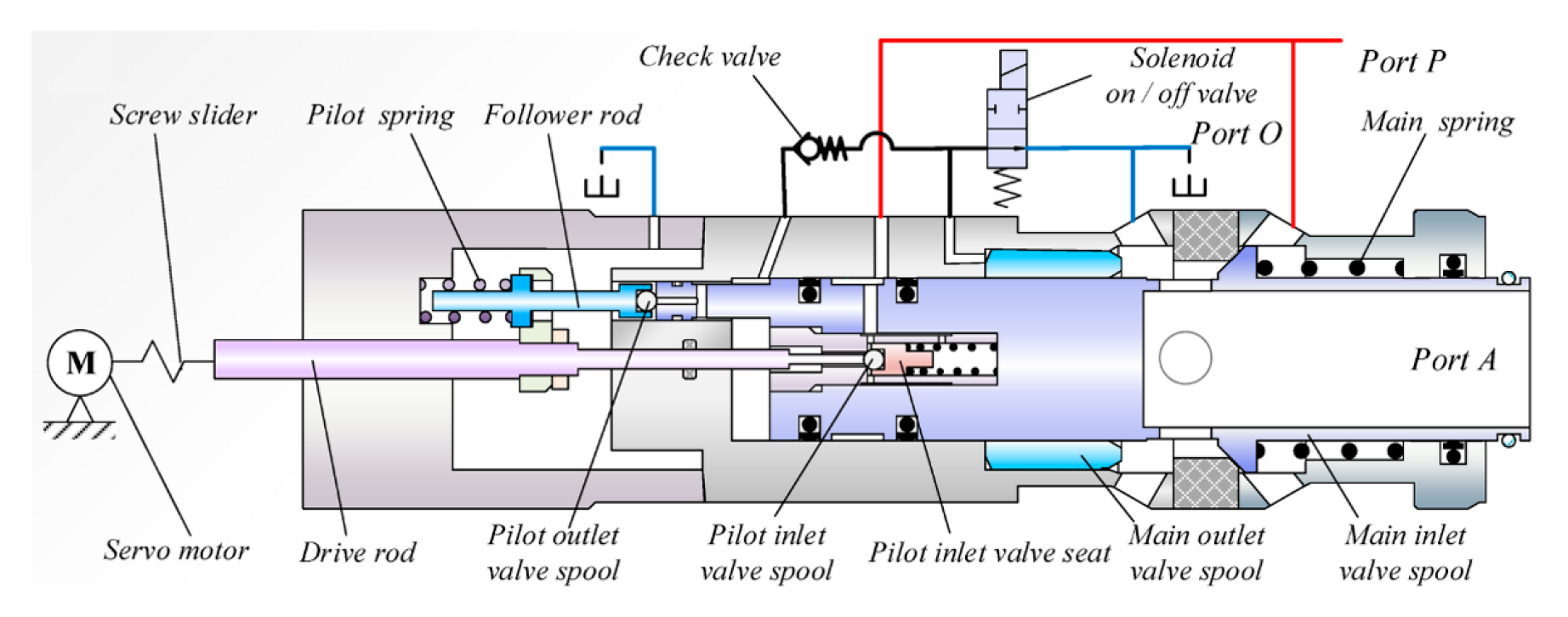
Zhang H et al. [118] proposed a high-pressure and high-flow proportional valve that is driven by a DC servo motor, as shown in Figure 9. The servo motor and the spool are connected by a screw slider. Forward and reverse rotation of the servo motor can drive the spool movement along the central axis. Li C [119] also used a DC servo motor to drive the spool, but the driving method was different. The output shaft of the DC servo motor is connected to the drive rod via a screw nut, and the drive rod is connected to the ball valve spool. In its initial state, the ball valve spool closes the valve port under the action of spring force. When the DC servo motor works, the DC servo motor rotational motion is converted to linear motion of the drive rod by the screw nut, which drives the ball valve spool to open the valve port.
A servo motor has the characteristics of high precision, fast response, good stability, and high efficiency, which makes it suitable for situations requiring high control precision. However, compared with ordinary motors, the structure of servo motors is complicated, the control and commissioning are more complex, the cost is high, and it is easy to generate electromagnetic interference. Therefore, when the control precision requirements are high, the use of the servo motor drive can meet the requirements. When the control accuracy requirements are not high, the general motor can meet the driving requirements. When choosing motors to drive the spool, not only control requirements but also control costs should be considered.
Lux J and Habegger C [120] introduced a method for driving a spool using a three-phase brushless DC motor. The three-phase brushless motor converts the rotary motion of the motor into a linear motion of the spool through a gear mechanism. Compared with brushed DC motors, brushless DC motors have no brushes in the rotor, reducing friction and brush losses, resulting in higher energy efficiency and a longer lifetime. There is no contact between the rotor and the stator, and noise is reduced, making it suitable for applications with high noise requirements. However, the drive circuit of brushless DC motors is complex and costly and requires a high-quality power supply. In addition, brushless DC motors have a slight vibration at low speeds, which decreases when the speed increases or the commutation frequency increases. Therefore, brushless DC motors should reduce the acceleration time when driving spools and are suitable for applications where spools are driven at high speeds.
Motor drives and their development are shown in Figure 10.

5. Hydraulic Valve Drive

Gao Q et al. [121] improved the conventional nozzle–flapper valve. High-speed switching valves were used instead of nozzles and flappers, and the traditional analog signal control was changed to digital signal control. The PWM voltage signal was applied to the high-speed switching valve, and the duty cycle of the PWM signal was changed to control the pressure difference between the two ends of the spool, thus driving the spool movement. Zhong Q et al. [122] used a high-speed switching valve instead of the conventional pilot proportional valve. The pressure difference between the two ends of the main spool is changed by adjusting the duty cycle of the drive signals of the two high-speed switching valves, and the pressure difference is used to drive the main spool movement. Subsequently, they [123] proposed a binary-coded digital valve array. Each binary-encoded digital valve array includes five switching valves and is connected to both ends of the spool through orifices. By controlling the on/off of the switching valves in the digital valve array, the pressure at the two ends of the spool can be changed, which in turn drives the spool motion. Kralev J et al. [124,125] proposed a pilot-operated micro-valve bridge-controlled proportional valve. When u(t) > 0, the micro-valve on the left side of the bridge opens and the proportional valve spool moves to the right; when u(t) < 0, the micro-valve on the right side of the bridge opens and the proportional valve spool moves to the left; when u(t) = 0, all the micro-valves of the bridge close and the proportional valve spool is located in the middle position; where u(t) is the drive voltage. Therefore, the spool can be driven by controlling the micro-valve switch, as shown in Figure 11.
Sitte A et al. [126] proposed a seat-type proportional valve [127]. One end of the spool is connected to the inlet pressure, and the other end is connected to the outlet pressure through a pilot proportional valve. By controlling the opening of the pilot proportional valve, the pressure difference between the two ends of the spool can be adjusted. Xiong XY and Huang JH [128] proposed controlling the pressure at both ends of the main spool using a switching valve, which replaces the pilot proportional valve in the scheme of André Sitte et al. During operation, a PWM signal is applied to the switching valve, and the differential pressure at both ends of the main spool is changed by varying the frequency of the PWM signal to drive the main spool. Li SM [129] introduced an improved bi-directional Valvistor valve. The pilot valve consists of two switching valves connected in parallel; one end of both switching valves is connected to one end of the main spool, and the other ends of the two switching valves are connected to the inlet and outlet. The bi-directional movement of the spool can be achieved by controlling the on/off of the two switching valves. Lin TL et al. [130,131] proposed a pilot-operated proportional pressure-reducing valve. Assume that the chambers at both ends of the main spool are A and B. The pressure in the A chamber is the inlet pressure. One end of the B chamber is connected to the A chamber through an orifice, and the other end is connected to the pilot proportional relief valve. By adjusting the pressure of the pilot proportional relief valve, the pressure of the B chamber can be adjusted, thus changing the pressure difference between the A and B chambers and realizing the drive of the main spool. Zhao RH et al. [132] proposed a new electro-hydraulic proportional directional valve. Assuming that the right chamber of the spool is A and the pressure is controlled by the switching valve, the left chamber of the spool is B, and the pressure is controlled by the proportional valve. In the switching valve circuit, the supply pressure is returned to the tank through the switching valve and the A chamber. In the proportional valve circuit, the supply pressure returns to the tank through the inlet hole, the proportional valve, the B chamber, and the outlet hole. There is a spring in the B chamber. When the switching valve is open, the pressure in the A chamber is maximum, and the spool is located on the leftmost side, driving the spool to the right through the control proportional valve. When the switching valve is closed, the pressure in the A chamber is minimum, and the spool is located on the rightmost side, and the spool is driven to the left by the control proportional valve.
Salloom MY and Samad Z [133] proposed a magnetorheological directional valve. The magnetorheological valve is equivalent to a switching valve. When the maximum current is applied to the magnetorheological valve, the valve is closed; when there is no current, the valve is opened. Four magnetorheological valves are placed into the valve body, and the direction of fluid flow in the directional valve can be changed by controlling the on/off of the magnetorheological valves. A summary of the hydraulic valve drive is shown in Table 3.
The hydraulic valve drive spool is generally used in pilot-operated control valves. The hydraulic valve controls the pressure at both ends of the main spool separately and changes the pressure difference between the two ends of the spool by controlling the action of the hydraulic valve, thus realizing the drive of the main spool. The use of hydraulic valves to drive the main spool movement can effectively reduce the fluctuations in system pressure and vibration and can improve the control accuracy and dynamic performance of the hydraulic system. The hydraulic valve independently controls the pressure at both ends of the spool, which can improve the robustness of the system. When the main valve system is disturbed, the pressure at both ends of the spool is not affected, and the displacement of the main spool can be steadily controlled by controlling the pilot hydraulic valve. The magnetorheological directional valve is used to control the direction of fluid flow, replacing the spool with a magnetorheological valve. The magnetorheological valve is embedded in the valve body, and the hydraulic system is controlled by controlling the opening and closing of the magnetorheological valve. However, compared with the solenoid drive method, the use of a hydraulic valve drive increases the complexity and cost of the system. In terms of control, when controlling two hydraulic valves, the degree of control complexity is essentially the same as for a conventional double-solenoid drive. When multiple valves are required to be driven together, multiple valves need to be controlled to work in concert, significantly increasing the control complexity. Therefore, the hydraulic valve drive method improves the static and dynamic performance of the system but increases the complexity and cost of the valve control system at the same time.

6. Other Drive Methods

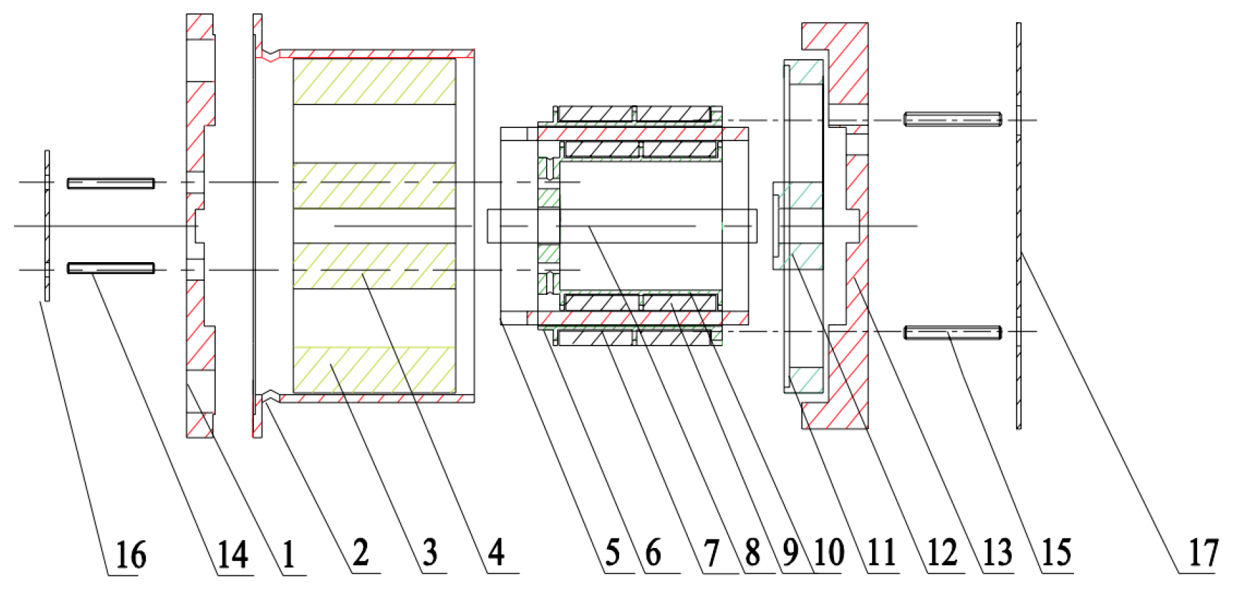
Meng B et al. [134,135] analyzed the structure and operating principles of a 2D mechanical valve and proposed a new 2D maglev valve. The new 2D maglev valve comprises a linear electro-mechanical converter (LEMC), a maglev coupler, and a 2D valve. The LEMC is connected to an external armature, and the linear motion of the external armature is converted into a rotary motion of the spool by the maglev coupling. There is a high-pressure orifice and a low-pressure orifice in the spool, and spool rotation changes the opening of the high-pressure and low-pressure orifices, thus changing the pressure at both ends of the spool, as shown in Figure 12. Wang XP et al. [136] proposed an electro-mechanical converter with two pushrods. The inner coil controls the movement of the inner rod, and the outer coil controls the movement of the outer rod. The inner and outer rods are connected to a proportional valve spool. By controlling the current in the coil, the inner and outer rods can be moved simultaneously, or one of them can be moved. The direction of movement of the inner and outer rods can be changed by changing the direction of the current. Thus, changing the current of the double pushrod electro-mechanical converter can drive the spool movement. This is shown in Figure 13. Chen J et al. [137] proposed the use of a cycloidal pump to drive spools. The cycloidal pump is a bi-directional hydraulic pump whose oil port is connected to the pressure chamber at both ends of the spool. The cycloidal pump can pump fluid from one of the chambers to the other, driving the spool movement by varying the differential pressure between the two ends.
Based on the existing spool drive, the original electro-mechanical converter has been improved to produce new spool drive methods, including maglev drive, double pushrod drive, and pump drive. Compared with the traditional solenoid drive, the new drive methods are improved in terms of control accuracy, stability, and reliability. However, the new spool drives are complex in structure, costly, and difficult to control. For high-precision control occasions, when the traditional drive method cannot meet the requirements, the new drive methods can be used. However, for general spool drive occasions, the conventional drive method can meet the requirements, and there is no need for a complex drive method.

7. Analysis

Solenoid drives are the most commonly used spool drive method. This drive method is simple in structure, mature in technology, and has a large driving force. However, the static and dynamic performance of solenoid drives are poor. To improve the drive performance of the solenoid, it can be optimized from both hardware and software aspects. In terms of hardware improvements, not only can the structure of conventional solenoids be improved, but also the hardware drive circuit can be optimized. The steady-state and dynamic performance of the solenoid drive can be improved by designing a fast-response circuit topology and selecting highly accurate electronic components. In terms of software improvements, the drive control algorithm and strategy of the solenoid can be improved. The solenoid has a low environmental impact during use and production. The solenoid works stably and is suitable for general spool drives.
The material expansion drive is the simplest drive method in terms of construction, where the spool is driven by applying an excitation signal to the expansion material. However, the displacement of the expansion material is small compared with the solenoid drive. In general, the use of material expansion to drive the spool movement does not meet the requirements, so additional displacement amplification is required. When adding a displacement amplification link, it not only reduces the efficiency of the mechanical drive but may also reduce the control accuracy. Therefore, when the spool movement stroke is very small, the material expansion direct drive method can be chosen. The structure of the material expansion drive is simple, and the drive can be realized by using the properties of the material itself. This type of drive does not require the production of other parts and is less polluting to the environment.
Motor drives include rotary motors and linear motors. When driving the spool linearly, the rotary motor requires adding a mechanical conversion link, and the linear motor can drive the spool directly. For 2D valve spools, the spool needs rotary motion and linear motion at the same time, so both rotary and linear motors require additional mechanical conversion links. Based on a solenoid, the voice coil motor adds permanent magnets and is relatively simple in construction. However, voice coil motors easily generate more thermal energy, which increases the motor temperature. This temperature increase not only affects the maximum current of the voice coil motor but also the magnetic characteristics of the permanent magnets. The small volume, fast response, and high accuracy of torque motors make them suitable for spool drive requirements at low speeds and large driving forces. As torque motors are limited by their output power, they are suited for pilot drives. However, torque motors have a small working stroke, high manufacturing accuracy, and a high price. The anti-interference performance of torque motors is not as good as that of electromagnets and voice coil motors. The stepper motor is controlled by digital pulse signals, and the speed is related to the input pulse frequency. Digital control, without digital/analog conversion, is easy to control. It has a wide speed range, high positional accuracy, and is not easily affected by voltage fluctuations and load changes. However, stepper motors are prone to out-of-step problems, which can lead to control errors. In addition, the position accuracy of the stepper motor is related to the motor’s drive power supply and structure. The higher the accuracy of the spool position, the more complex the structure of the drive power supply and motor, and, therefore, the more difficult and costly the control. Stepper motors are rotated by turning multiple steps. When the pulse frequency is constant, the larger the step angle, the lower the position accuracy, and the higher the speed of the stepper motor. When the pulse frequency is constant, the smaller the step angle, the higher the position accuracy, and the lower the speed of the stepper motor. When high position accuracy or drive speed is required, it can be achieved by changing the step angle. However, when high-precision and high-speed spool drives are required, the use of stepper motors cannot meet the requirements. To increase the drive speed, a stepper motor combined with a linear motor can be considered to drive the spool together. However, the combined drive of the two motors increases the complexity. The servo motor drive method can meet the requirements of driving speed and accuracy, but the cost is much higher than the stepper motor. Taking into account installation space and full drive performance, the researcher should try to choose conventional motors and avoid high-cost servo motors. The complex structure of motors requires using more electromagnetic components and materials, which may cause a certain amount of environmental pollution. During use, the motor has many working parts, so it is less reliable and prone to failure. Motor drives should be selected for occasions with high driving requirements.
The hydraulic valve drive is not interfered with by the main spool and can control the spool movement independently. Compared to solenoid drives, material expansion drives, and motor drives, hydraulic valve drives can obtain more stable system pressures and flows. As a result, the hydraulic valve drive not only provides better dynamic and static performance but also better system robustness. However, the hydraulic valve drive adds a hydraulic system, and the complexity of the overall hydraulic system increases significantly. There are several non-linear links in the hydraulic valve drive, making control more difficult and system commissioning more complex. The cost of hydraulic valves is higher than that of solenoids and motors, and the use of hydraulic valve drives can significantly increase production costs. In the hydraulic systems of high-end intelligent equipment, hydraulic valve drives can be used when the requirements for pressure and flow are high. However, for general hydraulic systems, the use of solenoids and motors can meet the drive requirements and reduce production costs.

8. Conclusions and Outlook

This paper reviews the current status and progress of research on hydraulic valve spool drive methods and analyzes the advantages and disadvantages of different spool drive methods. Spool drive methods include solenoid drive, material expansion drive, motor drive, hydraulic valve drive, and other drive methods. In order to facilitate the selection of a suitable drive method, the different drive methods were compared in terms of static performance, dynamic performance, control complexity, and cost of the hydraulic system. The following conclusions were drawn:
(1) The most commonly used spool drive method is the solenoid drive, whose driving force and stroke can meet most spool drive requirements. The static and dynamic performance of the solenoid drive is not as good as for motor drives and hydraulic valve drives, but its drive structure and control are relatively simple, and the most critical factor is its low cost. For general valve control systems, the drive requirements can be met.
(2) Of all the drive methods, the material expansion drive is the simplest in structure, has relatively low production costs, and offers high static and dynamic performance. For conventional spool drives, additional displacement amplification devices are generally required. For precision spool drives with small displacements, a direct drive method can be used.
(3) Compared with solenoid drives and material stretch drives, motor drives are more complex in structure and control and more expensive to produce. However, the drive performance of the motor drive is better than the first two drive methods. Motor drive methods generally require additional mechanical conversion links, which can reduce drive efficiency. Among rotating motors, stepper motors drive with high accuracy and DC motors drive with high speed, and the use of two motors combined can improve the static and dynamic performance of the system. Servo motors have the best drive performance but are far more expensive than conventional motors. Linear motors can drive the spool movement directly, saving the mechanical conversion link. Linear motors offer relatively high drive accuracy and have a high response speed, but poor heat dissipation affects the maximum drive force.
(4) Among the spool drive methods, the hydraulic valve drive has the best drive performance and reliability, but it has the most complex structure and control and the highest production costs. In the application process, unless the drive performance requirements are very high, other drive methods should be used as far as possible to reduce production costs and control difficulties.
The research in this paper provides a reference for selecting a suitable hydraulic valve drive. For users, the choice of spool drive needs to consider the cost, control complexity, environmental pollution, work stability, and other factors. This paper compares and analyzes the different drive methods, which is very important for users. In order to produce high-performance, low-cost, reliable, and environmentally friendly hydraulic valve actuators, several aspects should be investigated. Bringing together the ideas of researchers from different fields, the drive is optimized from multiple perspectives.
In future research, on the one hand, the drive method can be further optimized on the basis of existing spool drives. On the other hand, new drive methods can be explored. In the solenoid drive method, the solenoid structure can be optimized and the solenoid drive strategy can be changed in order to improve the drive performance. In terms of solenoid structure, the drive performance can be improved by changing the shape of the armature, the number of turns of the coil, the material, and the excitation signal. In terms of control, a more suitable drive method for the hydraulic system can be chosen, for example, by increasing the chattering signal to improve dynamic performance and using multiple closed-loop controls to improve control accuracy. However, increasing the flutter signal can affect the stability of the system. For the material expansion drive method, in addition to increasing the displacement amplification link, a highly sensitive pressure pilot control can also be used. Highly sensitive pressure pilot control means controlling the pressure at both ends of the main spool through a highly sensitive pressure pilot stage. A small displacement drive can make the pilot stage have a large pressure change. High-precision control methods will increase the complexity of the controller and increase production costs. Rotating motors should simplify the mechanical conversion link and improve drive efficiency. For the heat dissipation of linear motors, temperature sensors and heat dissipation devices should be added. The temperature sensor can monitor the temperature of the motor in real time, and the heat dissipation device can reduce the temperature of the motor. In hydraulic valve drives, pilot drive technology can be used to control the larger pressure of the main spool using a smaller pilot pressure, thus reducing the performance requirements of the hydraulic valve and reducing production costs. Currently, the most commonly used drive components are electro-mechanical converters. In practical applications, air–mechanical converters can also be used to realize the drive of the spool. In addition to the existing drive methods, new types of spool drives can also be considered, such as electrostatic actuators, ultrasonic motor drives, etc. To compensate for the disadvantages of different drive methods, the combined use of two or more spool drive methods can be considered to further improve drive performance.
This paper contributes to a comprehensive understanding of the current state of research on spool drives and the problems that exist with different drive methods. Solutions to the existing problems of spool drives are proposed, laying the foundation for further research. It can be seen that the research in this article helps to improve the driving performance of the valve core, thereby improving the performance of the hydraulic valve, which is very important for improving the responsiveness and control accuracy of the hydraulic system.

Author Contributions

Conceptualization, Y.L. and R.L.; methodology, Y.L.; software, Y.L.; validation, Y.L., R.L. and J.Y.; formal analysis, Y.L.; investigation, X.Y.; resources, R.L.; data curation, Y.L.; writing—original draft preparation, Y.L.; writing—review and editing, X.Y.; visualization, R.L.; supervision, R.L.; project administration, J.X.; funding acquisition, R.L. All authors have read and agreed to the published version of the manuscript.

Funding

This work was supported by the Major Innovation Project of Shandong Province (2022 CXGC020702), the Major Innovation Project of Shandong Province (2022CXGC020703), and the Shandong Provincial Science and Technology Department Small and Medium-Sized Enterprise Innovation Project (2021TSGC1419).

Institutional Review Board Statement

Not applicable.

Informed Consent Statement

Not applicable.

Data Availability Statement

The data presented in this study are available on request from the corresponding author.

Acknowledgments

I would like to thank my tutor, Ruichuan Li, for all his support and guidance. I would also like to thank my colleagues for their care and help in my daily work.

Conflicts of Interest

The authors declare no conflict of interest.

References

  1. Xu, B.; Shen, J.; Liu, S.; Su, Q.; Zhang, J. Research and Development of Electro-hydraulic Control Valves Oriented to Industry 4.0: A Review. Chin. J. Mech. Eng. 2020, 33, 29. [Google Scholar] [CrossRef]
  2. Wang, H.; Chen, Z.; Huang, J.; Quan, L.; Zhao, B. Development of High-Speed On–Off Valves and Their Applications. Chin. J. Mech. Eng. 2022, 35, 67. [Google Scholar] [CrossRef]
  3. Tamburrano, P.; Plummer, A.R.; Distaso, E.; Amirante, R. A Review of Direct Drive Proportional Electrohydraulic Spool Valves: Industrial State-of-the-Art and Research Advancements. J. Dyn. Syst. Meas. Control. 2019, 141, 020801. [Google Scholar] [CrossRef]
  4. Hao, Q.; Wu, W.; Liang, X.; Liu, Z. Effects of Structure Parameters on Abnormal Opening of Pilot-Operated Relief Valve Under Alternating Pressure. IEEE Access 2019, 7, 33932–33942. [Google Scholar] [CrossRef]
  5. Meng, B.; Shentu, S.N.; Lin, Q.; Ruan, J. Research on characteristics of pressure-resistant torque motor for 2D valve. In Proceedings of the 2016 IEEE International Conference on Aircraft Utility Systems (AUS), Beijing, China, 10–12 October 2016; pp. 73–76. [Google Scholar] [CrossRef]
  6. Han, Y.-M.; Han, C.; Kim, W.H.; Seong, H.Y.; Choi, S.-B. Control performances of a piezoactuator direct drive valve system at high temperatures with thermal insulation. Smart Mater. Struct. 2016, 25, 097003. [Google Scholar] [CrossRef]
  7. Milecki, A.; Ortmann, J. Electrohydraulic Valve with Two Stepping Motors. In Challenges in Automation, Robotics and Measurement Techniques, Proceedings of AUTOMATION-2016, Warsaw, Poland, 2–4 March 2016; Springer International Publishing: Berlin/Heidelberg, Germany, 2016; pp. 73–79. [Google Scholar] [CrossRef]
  8. Istanto, I.; Lee, I.-Y.; Huh, J.-Y.; Lee, H.-C. Controller design for a nozzle-flapper type servo valve with electric position sensor. J. Phys. Conf. Ser. 2019, 16, 29–35. [Google Scholar] [CrossRef]
  9. Wang, B.; Wang, T.; Chen, J. Design and Experiments of a New Type Pressure Proportional Valve. In Proceedings of the IEEE/ASME International Conference on Advanced Intelligent Mechatronics (AIM), Auckland, New Zealand, 9–12 July 2018; pp. 120–124. [Google Scholar] [CrossRef]
  10. Rybarczyk, D.; Owczarek, P.; Kubacki, A. Design of Control System for an Electrohydraulic Drive Based on the Valve with PMSM Motor. In Proceedings of the International Conference Challenges in Automation, Robotics and Measurement Techniques (Automation), Warsaw, Poland, 2–4 March 2016; pp. 63–71. [Google Scholar] [CrossRef]
  11. Han, C.; Choi, S.-B.; Han, Y.-M. A Piezoelectric Actuator-Based Direct-Drive Valve for Fast Motion Control at High Operating Temperatures. Appl. Sci. 2018, 8, 1806. [Google Scholar] [CrossRef]
  12. Wang, S.J.; Weng, Z.D.; Jin, B.; Cai, H.X. Multi-objective genetic algorithm optimization of linear proportional solenoid actuator. J. Braz. Soc. Mech. Sci. Eng. 2021, 43, 60. [Google Scholar] [CrossRef]
  13. Dülk, I.; Kovácsházy, T. A sensorless method for detecting spool position in solenoid actuators. Carpathian J. Electron. Comput. Eng. 2013, 6, 36–43. [Google Scholar]
  14. Liu, Y.-F.; Dai, Z.-K.; Xu, X.-Y.; Tian, L. Multi-domain modeling and simulation of proportional solenoid valve. J. Central South Univ. 2011, 18, 1589–1594. [Google Scholar] [CrossRef]
  15. Wu, W.; Wei, C.; Zhou, J.; Hu, J.; Yuan, S. Numerical and experimental nonlinear dynamics of a proportional pressure-regulating valve. Nonlinear Dyn. 2021, 103, 1415–1425. [Google Scholar] [CrossRef]
  16. Li, B.; Jiao, Z.; Wu, S.; Liu, X. Research on a new direct drive electro-hydraulic proportional pressure valve for aircraft braking system. In Proceedings of the 2016 IEEE/CSAA International Conference on Aircraft Utility Systems(AUS), Beijing, China, 10–12 October 2016; Institute of Electrical and Electronics Engineers Inc.: Piscataway, NJ, USA, 2016; pp. 1192–1196. [Google Scholar] [CrossRef]
  17. Chen, C.-P.; Chiang, M.-H. Development of Proportional Pressure Control Valve for Hydraulic Braking Actuator of Automobile ABS. Appl. Sci. 2018, 8, 639. [Google Scholar] [CrossRef]
  18. Ferrari, A.; Pizzo, P.; Rundo, M. Modelling and experimental studies on a proportional valve using an innovative dynamic flow-rate measurement in fluid power systems. Proc. Inst. Mech. Eng. Part C J. Mech. Eng. Sci. 2018, 232, 2404–2418. [Google Scholar] [CrossRef]
  19. Mahajan, P.; Kalkundri, P.; Shaikh, A.S. Precision Actuator Control for on/off Type Solenoid Valves using Pid Control Loop. In Proceedings of the IEEE 5th International Conference for Convergence in Technology (I2CT), Pune, India, 29–31 March 2019. [Google Scholar] [CrossRef]
  20. Ledvoň, M.; Hružík, L.; Bureček, A.; Vašina, M. Static and dynamic characteristics of proportional directional valve. In Proceedings of the 13th International Conference on Experimental Fluid Mechanics (EFM) Planetarium & Stefaniks Observ, Prague, Czech Republic, 13–16 November 2018. Experimental fluid mechanics 2018 (efm18). [Google Scholar] [CrossRef]
  21. Buono, D.; Senatore, A.; Frosina, E.; Gehlhoff, W.; Costin, I.I. Simulation and Experimental Investigations of a Digital High Speed Close Loop Proportional Directional Valve Using a Solenoid Technology. In Proceedings of the ASME/BATH 2016 Symposium on Fluid Power and Motion Control, FPMC2016, Bath, UK, 7–9 September 2016. [Google Scholar] [CrossRef]
  22. Amirante, R.; Catalano, L.A.; Poloni, C.; Tamburrano, P. Fluid-dynamic design optimization of hydraulic proportional directional valves. Eng. Optim. 2014, 46, 1295–1314. [Google Scholar] [CrossRef]
  23. Zuo, Q.; Sun, J.; Lu, Q.; Ruan, J. Experimental and numerical investigations of the ball-screw-type coupling in two-dimensional electro-hydraulic proportional directional valve. Adv. Mech. Eng. 2018, 10, 1687814018802509. [Google Scholar] [CrossRef]
  24. Raduenz, H.; Mendoza, Y.E.A.; Ferronatto, D.; Souza, F.J.; Bastos, P.P.d.C.; Soares, J.M.C.; De Negri, V.J. Online fault detection system for proportional hydraulic valves. J. Braz. Soc. Mech. Sci. Eng. 2018, 40, 331. [Google Scholar] [CrossRef]
  25. Gamble, J.B.; Vaughan, N.D. Comparison of Sliding Mode Control with State Feedback and PID Control Applied to a Proportional Solenoid Valve. J. Dyn. Syst. Meas. Control 1996, 118, 434–438. [Google Scholar] [CrossRef]
  26. Shi, W.; Wei, J.; Fang, J.; Li, M. Nonlinear cascade control of high-response proportional solenoid valve based on an extended disturbance observer. Proc. Inst. Mech. Eng. Part I J. Syst. Control Eng. 2019, 233, 921–934. [Google Scholar] [CrossRef]
  27. Acuña-Bravo, W.; Canuto, E.; Agostani, M.; Bonadei, M. Proportional electro-hydraulic valves: An Embedded Model Control solution. Control Eng. Pr. 2017, 62, 22–35. [Google Scholar] [CrossRef]
  28. Xie, F.; Zhou, R.; Wang, D.; Ke, J.; Guo, X.; Nguyen, V.X. Simulation Study on Static and Dynamic Characteristics of Electromagnet for Electro-Hydraulic Proportional Valve Used in Shock Absorber. IEEE Access 2020, 8, 41870–41881. [Google Scholar] [CrossRef]
  29. Lin, Y.Q.; Shi, H.Q. Novel Electro-hydraulic Proportional Valve Based on ARM. Autom. Appl. 2011, 5, 76–78. [Google Scholar]
  30. Meng, F.; Zhang, H.; Cao, D.; Chen, H. System Modeling, Coupling Analysis, and Experimental Validation of a Proportional Pressure Valve with Pulsewidth Modulation Control. IEEE/ASME Trans. Mechatron. 2016, 21, 1742–1753. [Google Scholar] [CrossRef]
  31. Meng, F.; Chen, H.; Liu, H.; Han, B.; Nie, X. The optimisation of a proportional solenoid valve design for heavy vehicle active suspension system. Int. J. Veh. Des. 2015, 68, 180. [Google Scholar] [CrossRef]
  32. Meng, F.; Tao, G.; Zhang, M.R.; Chen, H.Y. Optimization design and analysis of high speed wet proportional solenoid valve. Binggong Xuebao/Acta Armamentarii 2014, 35, 590–596. [Google Scholar] [CrossRef]
  33. Jiang, H.X. Research of Control Valve and Drive Strategy for Electrohydraulic Proportional Shift Control System of High Powre AT. Master’s Thesis, Harbin Institute of Technology, Harbin, China, 2019. [Google Scholar]
  34. Tian, H.; Zhao, Y. Coil Inductance Model Based Solenoid on–off Valve Spool Displacement Sensing via Laser Calibration. Sensors 2018, 18, 4492. [Google Scholar] [CrossRef]
  35. Hao, Y.; Quan, L.; Qiao, S.; Lianpeng, X.; Wang, X. Coordinated Control and Characteristics of an Integrated Hydraulic–Electric Hybrid Linear Drive System. IEEE/ASME Trans. Mechatron. 2022, 27, 1138–1149. [Google Scholar] [CrossRef]
  36. Yuan, Y.F.; Tao, G.L.; Liu, H.; Ban, W. Study of a Bidirectional Proportional Electromagnet. In Proceedings of the 2012 International Conference on Mechatronics and Control Engineering (ICMCE), Guangzhou, China, 29–30 November 2012; pp. 155–158. [Google Scholar] [CrossRef]
  37. Kim, D.S.; Lee, W.H.; Choi, B.O. Development of direct drive type pneumatic servo valve. In Proceedings of the 6th JFPS In-ternational Symposium on Fluid Power, Tsukuba, Japan, 7–10 November 2005. [Google Scholar]
  38. Li, Q.P.; Fang, P.; Ding, F. New Bi-directional proportional electro-mechanical converter. Chin. Hydraul. Pneum. 2005, 12, 62–63. [Google Scholar]
  39. Carpenter, R.; Fales, R. Mixed Sensitivity H-Infinity Control Design with Frequency Domain Uncertainty Modeling for a Pilot Operated Proportional Control Valve. In Proceedings of the ASME 2012 5th Annual Dynamic Systems and Control Conference Joint with the JSME 2012 11th Motion and Vibration Conference(DSCC 2012-MOVIC 2012), Fort Lauderdale, FL, USA, 17–19 October 2012; pp. 733–741. [Google Scholar] [CrossRef]
  40. Moustafa, N.; Fales, R. Stability of a Proportional Valve Control System with Backlash and Saturation. In Proceedings of the ASME/BATH 2013 Symposium on Fluid Power and Motion Control (FPMC), Fort Lauderdale, FL, USA, 6–9 October 2013. [Google Scholar] [CrossRef]
  41. Fan, X.; Fang, M.; He, Y.; Song, T. Modeling and dynamic analysis of a pilot-operated pressure-regulating solenoid valve used in automatic transmission with bond graphs. J. Braz. Soc. Mech. Sci. Eng. 2019, 41, 372. [Google Scholar] [CrossRef]
  42. Meng, F.; Zhang, H.; Cao, D.; Chen, H. System Modeling and Pressure Control of a Clutch Actuator for Heavy-Duty Automatic Transmission Systems. IEEE Trans. Veh. Technol. 2016, 65, 4865–4874. [Google Scholar] [CrossRef]
  43. Ouyang, T.; Li, S.; Huang, G.; Zhou, F.; Chen, N. Mathematical modeling and performance prediction of a clutch actuator for heavy-duty automatic transmission vehicles. Mech. Mach. Theory 2019, 136, 190–205. [Google Scholar] [CrossRef]
  44. Quan, L. A New Kind of Pilot Controlled Proportional Direction Valve with Internal Flow Feedback. Chin. J. Mech. Eng. 2010, 23, 60–65. [Google Scholar] [CrossRef]
  45. Zuo, Q.; Lu, Q.; Li, S.; Xing, T.; Ruan, J. Dynamic characteristics of 2D electro-hydraulic proportional directional valves with a ball-screw type axial compression-torsion coupling. China Mech. Eng. 2017, 28, 2049–2055. [Google Scholar]
  46. Ye, Q.; Chen, J. Dynamic analysis of a pilot-operated two-stage solenoid valve used in pneumatic system. Simul. Model. Pr. Theory 2009, 17, 794–816. [Google Scholar] [CrossRef]
  47. Li, Y.; Ding, F.; Shen, Y.D. Steady-state characteristics of proportional pilot-operated relief valve with low power consumption. China Mech. Eng. 2010, 21, 2921–2924. [Google Scholar]
  48. Shi, W.; Wei, J.; Fang, J.; Li, M.; Zhang, Q.; Qiao, X. Pressure Control of the Proportional Directional Control Valve Test Rig Based on the Fuzzy Proportional-Integral-Double-Integral Controller. In Proceedings of the ASME/BATH 2017 Symposium on Fluid Power and Motion Control (FPMC2017), Sarasota, FL, USA, 16–19 October 2017. [Google Scholar]
  49. He, L.H.; Liu, L. Study on drive and control technology of proportional valve for vehicle. J. Hunan Inst. Engi-Neering 2007, 4, 27–30. [Google Scholar] [CrossRef]
  50. Huang, Y. Design of A New Electro-Hydraulic Proportional Valve and Study of Its Control Method. Master’s Thesis, Hunan University, Changsha, China, 2007. [Google Scholar]
  51. Wang, H.; Wang, X.; Huang, J.; Wang, J.; Quan, L. A Novel Control Strategy for Pilot Controlled Proportional Flow Valve with Internal Displacement-Flow Feedback. J. Dyn. Syst. Meas. Control 2018, 140, 111014. [Google Scholar] [CrossRef]
  52. Wang, H.; Wang, X.; Huang, J.; Quan, L. Flow Control for a Two-Stage Proportional Valve with Hydraulic Position Feedback. Chin. J. Mech. Eng. 2020, 33, 93. [Google Scholar] [CrossRef]
  53. Liu, W.; Wei, J.; Fang, J.; Li, S. Hydraulic-feedback proportional valve design for construction machinery. Proc. Inst. Mech. Eng. Part C J. Mech. Eng. Sci. 2015, 229, 3162–3178. [Google Scholar] [CrossRef]
  54. Wang, H.; Wang, X.; Huang, J.; Quan, L. Performance Improvement of a Two-Stage Proportional Valve with Internal Hydraulic Position Feedback. J. Dyn. Syst. Meas. Control 2021, 143, 071005. [Google Scholar] [CrossRef]
  55. Huang, J.; Dai, J.; Quan, L.; Lan, Y. Performance of Proportional Flow Valve with Pilot Pressure Drop—Spool Opening Compensation. J. Dyn. Syst. Meas. Control 2017, 139, 011009. [Google Scholar] [CrossRef]
  56. D’Amore, M.; Pellegrinetti, G. Dissecting high-performance electrohydraulic valves. Mach. Des. 2001, 73, 84. [Google Scholar]
  57. Lisowski, E.; Filo, G.; Rajda, J. Pressure compensation using flow forces in a multi-section proportional directional control valve. Energy Convers. Manag. 2015, 103, 1052–1064. [Google Scholar] [CrossRef]
  58. DeRose, D. Typical Proportional and Servo Valve Control Systems. Fluid Power J. 2003, 10, 8–15. [Google Scholar]
  59. Amirante, R.; Distaso, E.; Tamburrano, P. Sliding spool design for reducing the actuation forces in direct operated proportional directional valves: Experimental validation. Energy Conv. Manag. 2016, 119, 399–410. [Google Scholar] [CrossRef]
  60. Tic, V.; Rotovnik, A.; Lovrec, D. Impact of Proportional Valves’ Differences to Ensure Uniform Motion of Hydraulic Motors. Int. J. Simul. Model. 2021, 20, 52–63. [Google Scholar] [CrossRef]
  61. Jin, B.; Zhu, Y.-G.; Li, W.; Zhang, D.-S.; Zhang, L.-L.; Chen, F.-F. A differential control method for the proportional directional valve. J. Zhejiang Univ. Sci. C 2014, 15, 892–902. [Google Scholar] [CrossRef]
  62. Xiong, Y.; Wei, J.; Feng, R. Adaptive robust control of a high-response dual proportional solenoid valve with flow force compensation. Proc. Inst. Mech. Eng. Part I J. Syst. Control Eng. 2015, 229, 3–26. [Google Scholar] [CrossRef]
  63. Zhu, Y.; Jin, B. Analysis and modeling of a proportional directional valve with nonlinear solenoid. J. Braz. Soc. Mech. Sci. Eng. 2016, 38, 507–514. [Google Scholar] [CrossRef]
  64. Lee, I.-Y.; Oh, D.-H.; Ji, S.-W.; Yun, S.-N. Control of an overlap-type proportional directional control valve using input shaping filter. Mechatronics 2015, 29, 87–95. [Google Scholar] [CrossRef]
  65. Owczarek, P.; Rybarczyk, D.; Kubacki, A. Dynamic Model and Simulation of Electro-Hydraulic Proportional Valve. In Proceedings of the International Conference on Automation, Warsaw, Poland, 15–17 March 2017; pp. 99–107. [Google Scholar] [CrossRef]
  66. Braun, T.; Reuter, J.; Rudolph, J. Position Observation for Proportional Solenoid Valves by Signal Injection. In Proceedings of the 7th IFAC Symposium on Mechatronic Systems (MECHATRONICS) Loughborough Univ, Leicestershire, UK, 5–8 September 2016; pp. 74–79. [Google Scholar] [CrossRef]
  67. Bayat, F.; Tehrani, A.F.; Danesh, M. Finite element analysis of proportional solenoid characteristics in hydraulic valves. Int. J. Automot. Technol. 2012, 13, 809–816. [Google Scholar] [CrossRef]
  68. Zavarehi, M.K.; Lawrence, P.; Sassani, F. Nonlinear modeling and validation of solenoid-controlled pilot-operated servovalves. IEEE/ASME Trans. Mechatron. 1999, 4, 324–334. [Google Scholar] [CrossRef]
  69. Hanson, N. Hydraulic Proportional and Closed Loop System Design; Lohr a. Main; Tech. Rep.; Bosch Rexroth: Horb am Neckar, Germany, 2010. [Google Scholar]
  70. Hanson, N. Selecting Proportional Valves and High Response Valves; Rexroth Bosch Group: Lohr am Main, Germany, 2010. [Google Scholar]
  71. Saleem, S. Pilot Operated Cartridge Valve-Dynamic Characteristics Measurements for Energy Efficient Operation and Application. Master’s Thesis, Aalto University School of Engineering, Aalto, Finland, 2018. [Google Scholar]
  72. Xu, B.; Su, Q.; Zhang, J.; Lu, Z. A dead-band model and its online detection for the pilot stage of a two-stage directional flow control valve. Proc. Inst. Mech. Eng. Part C J. Mech. Eng. Sci. 2016, 230, 639–654. [Google Scholar] [CrossRef]
  73. Xu, B.; Su, Q.; Zhang, J.; Lu, Z. Analysis and compensation for the cascade dead-zones in the proportional control valve. ISA Trans. 2017, 66, 393–403. [Google Scholar] [CrossRef] [PubMed]
  74. Lu, Z.; Zhang, J.; Xu, B.; Wang, D.; Su, Q.; Qian, J.; Yang, G.; Pan, M. Deadzone compensation control based on detection of micro flow rate in pilot stage of proportional directional valve. ISA Trans. 2019, 94, 234–245. [Google Scholar] [CrossRef] [PubMed]
  75. Zhang, J.; Lu, Z.; Xu, B.; Su, Q. Investigation on the dynamic characteristics and control accuracy of a novel proportional directional valve with independently controlled pilot stage. ISA Trans. 2019, 93, 218–230. [Google Scholar] [CrossRef] [PubMed]
  76. Zhang, J.; Wang, D.; Xu, B.; Lu, Z.; Gan, M.; Su, Q. Modeling and Experimental Validation of the Time Delay in a Pilot Operated Proportional Directional Valve. IEEE Access 2018, 6, 30355–30369. [Google Scholar] [CrossRef]
  77. Meng, B.; Zhu, C.; Xu, H.; Dai, M.; Li, S. Analytical and Experimental Investigations of Novel Maglev Coupling Based on Opposed Halbach Array for a 2D Valve. Actuators 2021, 10, 61. [Google Scholar] [CrossRef]
  78. Angelov, I.; Kamberov, K.; Mitov, A.; Ivanov, T. Implementation of Piezoelectric Actuators for Pilot Valve of High Response Hydraulic Servo Valve. In Proceedings of the 4th European-Alliance-for-Innovation (EAI) International Conference on Future Access Enablers of Ubiquitous and Intelligent Infrastructures (FABULOUS), Sofia, Bulgaria, 28–29 March 2019; pp. 318–326. [Google Scholar] [CrossRef]
  79. Park, Y.-J.; Kim, B.-G.; Jeon, J.-C.; Jung, D.; Choi, S.-B. The Effect of Spool Displacement Control to the Flow Rate in the Piezoelectric Stack-Based Valve System Subjected to High Operating Temperature. Actuators 2021, 10, 239. [Google Scholar] [CrossRef]
  80. Zhang, Z.M.; Gong, Y.J.; Hou, J.Y.; Li, G.; Wu, H.P.; Wang, Z.W. Design and static experiments of water hydraulic throttle valve with direct piezoelectric actuation. Mei T’an Hsueh Pao/J. China Coal. Soc. 2014, 39, 583–588. [Google Scholar] [CrossRef]
  81. Stefanski, F.; Minorowicz, B.; Persson, J.; Plummer, A.; Bowen, C. Non-linear control of a hydraulic piezo-valve using a generalised Prandtl–Ishlinskii hysteresis model. Mech. Syst. Signal Process. 2017, 82, 412–431. [Google Scholar] [CrossRef]
  82. Murrenhoff, H. Innovative Designs and Control Circuits for Proportional Valves. In Proceedings of the SAE International Off-Highway Congress-Colocated with CONEXPO-CON/AGG, Las Vegas, NV, USA, 19–21 March 2002. [Google Scholar] [CrossRef]
  83. Tamburrano, P.; Amirante, R.; Distaso, E.; Plummer, A.R. Full simulation of a piezoelectric double nozzle flapper pilot valve coupled with a main stage spool valve. In Proceedings of the 73rd Conferengy Proce of the Italdian-Thermal-Machines-Engineering-Association (ATI), Pisa, Italy, 12–14 September 2018; pp. 487–494. [Google Scholar] [CrossRef]
  84. Sangiah, D.K.; Plummer, A.R.; Bowen, C.R.; Guerrier, P. Modelling and Experimental Validation of a Novel Piezohydraulic Servovalve. In Proceedings of the ASME 2011 Dynamic Systems and Control Conference and Bath/ASME Symposium on Fluid Power and Motion Control, DSCC 2011, Arlington, VA, USA, 31 October–2 November 2011; American Society of Mechanical Engineers (ASME): New York, NY, USA, 2011; pp. 343–350. [Google Scholar] [CrossRef]
  85. Wang, X.; Li, W.; Ruan, Z.; Zheng, J.; Sun, S. Research on Properties of Water Hydraulic Servo Valve Driven by Diphase Oppositing Giant Magnetostrictive Actuator. In Proceedings of the International Conference on Measuring Technology and Mechatronics Automation (ICMTMA), Changsha, China, 13–14 March 2010; pp. 143–146. [Google Scholar] [CrossRef]
  86. Zhou, R.; Meng, L.; Yuan, X. Experimental Test and Feasibility Analysis of Hydraulic Cylinder Position Control Based on Pressure Detection. Processes 2022, 10, 1167. [Google Scholar] [CrossRef]
  87. Fu, Y.L.; Zhou, G.Z. Research on valve and pump combined control of digital actuator. In Proceedings of the ASME 2013 International Mechanical Engineering Congress and Exposition (IMECE), San Diego, CA, USA, 15–21 November 2013; ASME: New York, NY, USA, 2013. [Google Scholar]
  88. Su, L.; Xue, F. Spool limit electro-hydraulic digital valve control system and position precision control. Hydraul. Pneum. Seals 2022, 42, 53–56. [Google Scholar] [CrossRef]
  89. Rybarczyk, D. Concept and modelling of the electrohydraulic valve with DC and stepper motors. In Proceedings of the 3rd InMATErnationalC Web Conference of Computational Methods in Engineering Science (CMES), Kazimierz Dolny, Poland, 22–24 November 2018. [Google Scholar] [CrossRef]
  90. Rybarczyk, D.; Milecki, A. Electrohydraulic Drive with a Flow Valve Controlled by a Permanent Magnet Synchronous Motor. Trans. FAMENA 2020, 44, 31–44. [Google Scholar] [CrossRef]
  91. Milecki, A.; Ortmann, J. Electrohydraulic linear actuator with two stepping motors controlled by overshoot-free algorithm. Mech. Syst. Signal Process. 2017, 96, 45–57. [Google Scholar] [CrossRef]
  92. Milecki, A.; Ortmann, J. Influences of Control Parameters on Reduction of Energy Losses in Electrohydraulic Valve with Stepping Motors. Energies 2021, 14, 6114. [Google Scholar] [CrossRef]
  93. Milecki, A.; Rybarczyk, D. Modelling of an Electrohydraulic Proportional Valve with a Synchronous Motor. Strojniski Vestn-J. Mech. Eng. 2015, 61, 517–522. [Google Scholar] [CrossRef]
  94. Owczarek, P.; Rybarczyk, D.; Gośliński, J.; Owczarkowski, A. The High-Resolution Camera in Estimation of the Position of the Hydraulic Valve Spool. Adv. Intell. Syst. Comput. 2014, 267, 623–630. [Google Scholar] [CrossRef]
  95. Sheng, L.; Jian, R.; Bin, M. Research for the characteristics of electro-mechanical converter for 2D digital servo valve. In Proceedings of the IEEE 10th International Conference on Industrial Informatics, INDIN 2012, Beijing, China, 25–27 July 2012; pp. 719–724. [Google Scholar]
  96. Nguyen, T.H.; Do, T.C.; Ahn, K.K. Independent metering valve: A review of advances in hydraulic machinery. J. Drive Control. 2020, 17, 54–71. [Google Scholar]
  97. Suzuki, K.; Akazawa, S.; Nakao, Y. Development of Cam-Drive Type Proportional Valve for Water Hydraulics. Int. J. Autom. Technol. 2012, 6, 450–456. [Google Scholar] [CrossRef]
  98. Meng, B.; Xu, H.; Liu, B.; Dai, M.; Zhu, C.; Li, S. Novel Magnetic Circuit Topology of Linear Force Motor for High Energy Utilization of Permanent Magnet: Analytical Modelling and Experiment. Actuators 2021, 10, 32. [Google Scholar] [CrossRef]
  99. Bang, Y.-B.; Lee, K.-I.; Joo, C.-S.; Hur, J.-W. Two-stage electrohydraulic servovalve using stack-type piezoelectric elements. Proc. Inst. Mech. Eng. Part C J. Mech. Eng. Sci. 2004, 218, 53–65. [Google Scholar] [CrossRef]
  100. Ye, R.K. Research on a two-Way Electro-Hydraulic Cartridge Throttle Valve with Spool Position Electrical Feedback. Master’s Thesis, Harbin Institute of Technology, Harbin, China, 2018. [Google Scholar]
  101. Plummer, A. Electrohydraulic servovalves–past, present, and future. In Proceedings of the 10th International Fluid Power Conference, Dresden, Germany, 8–10 March 2016. [Google Scholar]
  102. Meng, B.; Dai, M.; Zhu, C.; Zhang, C.; Ding, C.; Ruan, J. Analytical Modelling and Experiment of Novel Rotary Electro-Mechanical Converter with Negative Feedback Mechanism for 2D Valve. Chin. J. Mech. Eng. 2022, 35, 122. [Google Scholar] [CrossRef]
  103. Meng, B.; Dai, M.; Zhu, C.; Xu, H.; Jia, W.; Li, S. Investigation of Characteristics of a Novel Torque Motor Based on an Annulus Air Gap. Machines 2021, 9, 131. [Google Scholar] [CrossRef]
  104. Meng, B.; Zhu, L.; Heng, Y.; Xu, H.; Li, S.; Ruan, J. Investigation on flat torque-angle characteristic of torque motor based on magnetic saturation of tooth tip. IET Power Electron. 2023, 16, 357–374. [Google Scholar] [CrossRef]
  105. Gastaldi, L.; Pastorelli, S.; Sorli, M. Static and Dynamic Experimental Investigation of a Pneumatic Open Loop Proportional Valve. Exp. Tech. 2016, 40, 1377–1385. [Google Scholar] [CrossRef]
  106. Nielsen, B. Controller Development for a Separate Meter-In Separate Meter-Out Fluid Power Valve for Mobile Applications. Ph.D. Thesis, Aalborg University, Aalborg, Denmark, 2023. [Google Scholar]
  107. Han, M.; Liu, Y.; Zheng, K.; Ding, Y.; Wu, D. Investigation on the modeling and dynamic characteristics of a fast-response and large-flow water hydraulic proportional cartridge valve. Proc. Inst. Mech. Eng. Part C J. Mech. Eng. Sci. 2020, 234, 4415–4432. [Google Scholar] [CrossRef]
  108. Han, M.; Liu, Y.; Liao, Y.; Wang, S. Investigation on the Modeling and Dynamic Characteristics of a Novel Hydraulic Proportional Valve Driven by a Voice Coil Motor. Strojniski Vestn.-J. Mech. Eng. 2021, 67, 223–234. [Google Scholar] [CrossRef]
  109. Baoren, L.; Longlong, G.; Gang, Y. Modeling and Control of a Novel High-Pressure Pneumatic Servo Valve Direct-Driven by Voice Coil Motor. J. Dyn. Syst. Meas. Control. 2013, 135, 014507. [Google Scholar] [CrossRef]
  110. Miyajima, T.; Fujita, T.; Sakaki, K.; Kawashima, K.; Kagawa, T. Development of a digital control system for high-performance pneumatic servo valve. Precis. Eng. 2007, 31, 156–161. [Google Scholar] [CrossRef]
  111. Kawashima, K.; Arai, T.; Tadano, K.; Fujita, T.; Kagawa, T. Development of coarse/fine dual stage using pneumatically driven bellows actuator and cylinder with air bearings. Precis. Eng. 2010, 34, 526–533. [Google Scholar] [CrossRef]
  112. Zhang, Z.M.; Meng, F.Y.; Hou, J.Y.; Wu, H.P.; Ning, D.Y.; Gong, S.J. Design, simulation and experiments of water hydraulic throttle valve with direct voice coil motor actuation. Mei T’an Hsueh Pao/J. China Coal. Soc. 2017, 42, 275–281. [Google Scholar] [CrossRef]
  113. Xu, X.; Quan, L.; Wang, X. New High Performance Electro-hydraulic Proportional Valve and Its Performance. J. Mech. E 2020, 56, 233–238. [Google Scholar] [CrossRef]
  114. Zhu, J.W.; Xu, X.Q.; Wang, X.P.; Liu, Z.H. Research on two-way proportional controller for electro-hydraulic proportional valve. Chin. Hydraul. Pneum. 2018, 4, 32–36. [Google Scholar] [CrossRef]
  115. Zhang, L.T.; Xu, X.Q.; Feng, X.G. Electro-hydraulic proportional valve based on moving-coil electro-mechanical transformer. Mach. Tool Hydraul. 2018, 46, 45–48. [Google Scholar] [CrossRef]
  116. Ledvoň, M.; Polášek, T.; Bureček, A.; Hružík, L. Modeling and dynamic analysis of proportional directional valve. In Proceedings of the 38th Meeting of Departments-of-Fluid-Mechanics-and-Thermodynamics, Liptovsky Mikulas, Slovakia, 19–21 June 2019. [Google Scholar] [CrossRef]
  117. Lu, L.; Xia, F.Y.; Yin, Y.B.; Yuan, J.Y.; Guo, S.R. Spool stuck mechanism of ball-type rotary direct drive pressure servo valve. Che-chiang Ta Hsueh Hsueh Pao, Kung Hsueh Pan/J. Zhejiang Univ. Eng. Sci. 2019, 53, 1265–1273 and 1339. [Google Scholar] [CrossRef]
  118. Zhang, H.; Liao, Y.; Tao, Z.; Lian, Z.; Zhao, R. Modeling and Dynamic Characteristics of a Novel High-Pressure and Large-Flow Water Hydraulic Proportional Valve. Machines 2022, 10, 37. [Google Scholar] [CrossRef]
  119. Li, C. Flow Characteristics of Large Flow and Water Based Electro-Hydraulic Proportional Valve Port for Mining. Master’s Thesis, Taiyuan University of Technology, Taiyuan, China, 2020. [Google Scholar]
  120. Lux, J.; Habegger, C. New Generation of Intelligent Electromechanical Valve Actuation; RWTH Aachen University: Aachen, Germany, 2018; pp. 395–403. [Google Scholar]
  121. Gao, Q.; Zhu, Y.; Wu, C.; Jiang, Y. Development of a novel two-stage proportional valve with a pilot digital flow distribution. Front. Mech. Eng. 2021, 16, 420–434. [Google Scholar] [CrossRef]
  122. Zhong, Q.; Xu, E.-G.; Jia, T.-W.; Yang, H.-Y.; Zhang, B.; Li, Y.-B. Dynamic performance and control accuracy of a novel proportional valve with a switching technology-controlled pilot stage. J. Zhejiang Univ. A 2022, 23, 272–285. [Google Scholar] [CrossRef]
  123. Gao, Q.; Zhu, Y.; Liu, J. Dynamics Modelling and Control of a Novel Fuel Metering Valve Actuated by Two Binary-Coded Digital Valve Arrays. Machines 2022, 10, 55. [Google Scholar] [CrossRef]
  124. Kralev, J.; Mitov, A.; Slavov, T. Robust μ-Controller for Hydraulic Spool Valve, Pilot Operated with Switching Micro Valves. Energies 2021, 14, 4817. [Google Scholar] [CrossRef]
  125. Mitov, A.; Kralev, J.; Slavov, T.; Angelov, I. Analytical Modelling of Hydraulic Proportional Spool Valve Pilot Operated with Switching Micro Valves. In Proceedings of the 6th International Symposium on Environment-Friendly Energies and Applications (EFEA) Tech Univ Sofia, Ctr Res & Design Human Comfort, Energy & Environm, Sofia, Bulgaria, 24–26 March 2021. [Google Scholar] [CrossRef]
  126. Sitte, A.; Maschinenbau, T.U.D.I.F.M.; Koch, O.; Liu, J.; Tautenhahn, R.; Weber, J. Multidimensional flow mapping for proportional valves. In Proceedings of the 12th International Fluid Power Conference, Dresden, Germany, 12–14 October 2020. [Google Scholar] [CrossRef]
  127. Wu, R.N.; Yu, Z.Y.; Wang, L. The design of electromagnetic safety cartridge valve with position monitoring. Hydraul. Pneum. Seals 2016, 36, 23–25. [Google Scholar] [CrossRef]
  128. Xiong, X.; Huang, J. Performance of a flow control valve with pilot switching valve. Proc. Inst. Mech. Eng. Part I J. Syst. Control Eng. 2018, 232, 178–194. [Google Scholar] [CrossRef]
  129. Li, S.M. Research on Nonlinear Correction Method of Digital Control Electro-Hydraulic Proportioanl Cartridge Flow Valve. Ph.D. Thesis, Taiyuan University of Technology, Taiyuan, China, 2015. [Google Scholar]
  130. Lin, T.; Chen, Q.; Ren, H.; Lv, R.; Miao, C.; Chen, Q. Computational fluid dynamics and experimental analysis of the influence of the energy recovery unit on the proportional relief valve. Proc. Inst. Mech. Eng. Part C J. Mech. Eng. Sci. 2018, 232, 697–705. [Google Scholar] [CrossRef]
  131. Lin, T.; Chen, Q.; Ren, H.; Miao, C.; Chen, Q.; Fu, S. Influence of the energy regeneration unit on pressure characteristics for a proportional relief valve. Proc. Inst. Mech. Eng. Part I J. Syst. Control Eng. 2017, 231, 189–198. [Google Scholar] [CrossRef]
  132. Zhao, R.; Liao, Y.; Lian, Z.; Li, R.; Guo, Y. Research on the performance of a novel electro-hydraulic proportional directional valve with position-feedback groove. Proc. Inst. Mech. Eng. Part E J. Process. Mech. Eng. 2021, 235, 1930–1944. [Google Scholar] [CrossRef]
  133. Salloom, M.Y.; Samad, Z. Magneto-rheological directional control valve. Int. J. Adv. Manuf. Technol. 2012, 58, 279–292. [Google Scholar] [CrossRef]
  134. Xu, H.; Meng, B.; Zhu, C.; Li, S.; Ruan, J. Novel resonance stability criterion for the 2D magnetically levitated servo-proportional valve. Proc. Inst. Mech. Eng. Part C J. Mech. Eng. Sci. 2022, 236, 4713–4730. [Google Scholar] [CrossRef]
  135. Meng, B.; Xu, H.; Ruan, J.; Li, S. Theoretical and experimental investigation on novel 2D maglev servo proportional valve. Chin. J. Aeronaut. 2021, 34, 416–431. [Google Scholar] [CrossRef]
  136. Wang, X.; Quan, L.; Luan, S.; Xu, X. Dynamic and Static Characteristics of Double Push Rods Electromechanical Converter. Chin. J. Mech. Eng. 2019, 32, 62. [Google Scholar] [CrossRef]
  137. Chen, J.; Shu, J.P.; Li, M.; Zhou, Q.; Su, Z.M. Research on Novel Self-Spinning High Speed On/Off Valve Based on Fuzzy-Logic Parameter Self-Tuning PID Controller. In Proceedings of the 3rd International Conference on Manufacturing Science and Engineering (ICMSE), Xiamen, China, 27–29 March 2012; pp. 1448–1452. [Google Scholar] [CrossRef]
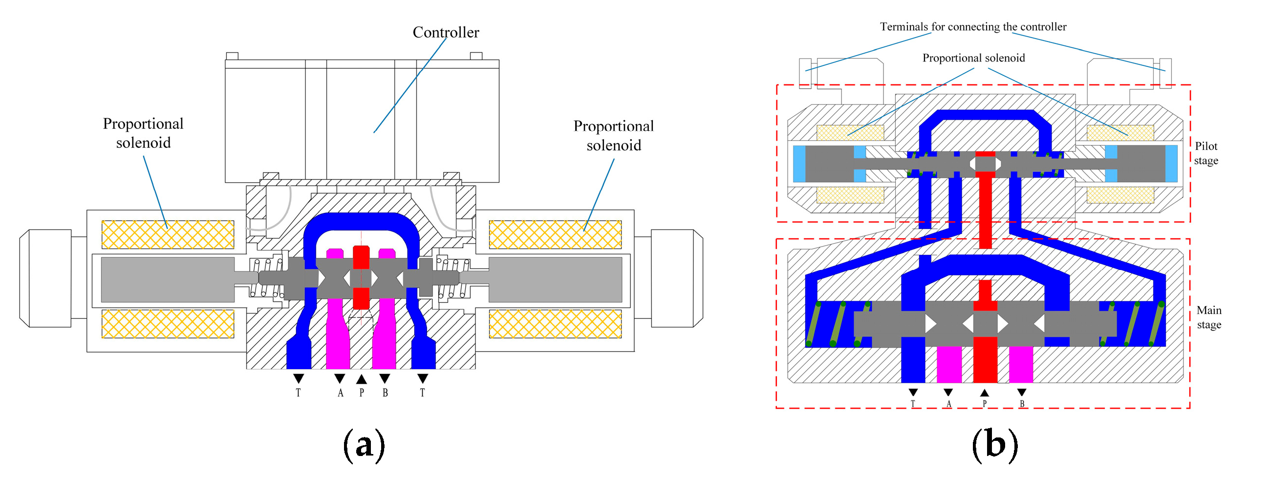
Figure 1. Direct-operated and pilot-operated hydraulic control valves. (a) Direct operated. (b) Pilot operated.
Processes 11 02537 g001
Figure 2. Related contents of the review.
Processes 11 02537 g002
Figure 3. Proportional directional valve driven by a single proportional solenoid [20].
Processes 11 02537 g003
Figure 4. Two pilot-operated proportional valves with the single solenoid drive. (a) Solenoid-driven cone valve [46]. (b) Solenoid-driven proportional valve [52].
Processes 11 02537 g004
Figure 5. 2D electro-hydraulic proportional directional valve with double solenoid drive [77].
Processes 11 02537 g005
Figure 6. Schematic diagram of the piezoelectric stacked actuator push/pull spool. (a) push spool [11]. (b) pull spool [79].
Processes 11 02537 g006
Figure 7. Schematic diagram of the two torque motors driving the spool [102,104].
Processes 11 02537 g007
Figure 8. New hydraulic proportional valve driven by voice coil motor [108].
Processes 11 02537 g008
Figure 9. Servo-motor-driven high-pressure and high-flow proportional valve [118].
Processes 11 02537 g009
Figure 10. Motor drives and their development.
Processes 11 02537 g010
Figure 11. Pilot-operated micro-valve bridge-controlled proportional valve [124].
Processes 11 02537 g011
Figure 12. 2D maglev valve [135].
Processes 11 02537 g012
Figure 13. Double pushrod electro-mechanical converter [136]. 1. Front cover; 2. shell; 3. outer permanent magnet; 4. inner permanent magnet; 5. sleeve; 6. outer coil frame; 7. outer coil; 8. iron core; 9. inner coil; 10. inner coil frame; 11. outer limit block; 12. inner limit block; 13. rear cover; 14. inner rod; 15. outer rod; 16. output unit; 17. output unit.
Processes 11 02537 g013
Table 1. Summary of the solenoid-driven spool.
AuthorsNumber of SolenoidsSolenoid TypeDrive TypeTypes of Controlled ValvesControl Method
Dülk I et al. [13,14,41,42,51,52,53,54,55,65,66]1 or 2Proportional solenoidDirect drive or pilot driveProportional flow valveCurrent or voltage control
Wu W et al. [15,16]1Proportional solenoidDirect driveProportional pressure control valveCurrent control
Chen CP and Chiang MH [17]1Proportional solenoidDirect driveProportional pressure control valveVoltage control
Ferrari A et al. [18,71,72,73,74,75,76]1 or 2Proportional solenoidDirect drive or pilot driveProportional flow directional valvePWM current control or voltage control
Mahajan P et al. [19]1Proportional solenoidDirect driveSwitching solenoid valvePWM voltage control
Ledvon M et al. [20,21,22,23,24,44,57,58,59,60,61,62,63,64]1 or 2Proportional solenoidDirect drive or pilot driveProportional directional valvePWM voltage control
Gamble JB et al. [25,26,27,46,47,48,49,50]1Proportional solenoidDirect drive or pilot-driven cone valveProportional solenoid valvePWM voltage control
Lin YQ et al. [29,67]1 or 2Proportional solenoidDirect driveProportional valvePWM voltage control
Meng F et al. [30,31,32,33]1Proportional solenoidDirect driveBall valvePWM current control
Tian H and Zhao Y [34]1Switching solenoidDirect driveSwitching valveSquare wave voltage control
Hao YX et al. [35]1Bi-directional proportional solenoidDirect driveProportional valveVoltage control
Yuan YF et al. [36,37]1Bi-directional proportional solenoidDirect drivePneumatically controlled hydraulic valveCurrent control
Li QP et al. [38]1Bi-directional proportional solenoidDirect driveElectro-hydraulic proportional and servo valvesCurrent control
Carpenter R et al. [39,40]1Proportional solenoidPilot drivePilot control valveVoltage control
Zuo Q et al. [45,77]1 or 2Proportional solenoidCompression–torsion coupling pilot driveProportional directional valveCurrent control
D’Amore M and Pellegrinetti G [56]1Bi-directional proportional solenoidPilot driveNozzle–flapper servo valveCurrent control
Zavarehi M K et al. [68]2Proportional solenoidPilot driveElectro-hydraulic servo valveVoltage control
Table 2. Summary of the material expansion drive.
AuthorsActuatorTypes of Controlled ValvesDrive TypeNumber of ActuatorsUnidirectional/Bi-directional Drive
Han YM et al. [6,11,78,79]Piezoelectric stacking actuatorProportional valveFlexible beam mechanism drive1Unidirectional drive
Zhang ZM et al. [80]Piezoelectric stacking actuatorThrottle control valveDirect drive1Unidirectional drive
Stefanski F et al. [81]Piezoelectric ring benderPiezoelectric valveDirect drive1Bi-directional drive
Murrenhoff H [82]Piezoelectric stacking actuatorPilot-operated piezoelectric valvePilot drive2Bi-directional drive
Tamburrano P et al. [83]Piezoelectric ring benderNozzle–flapper servo valvePilot drive1Bi-directional drive
Sangiah DK et al. [84]Bimorph actuatorNozzle–flapper servo valvePilot drive1Bi-directional drive
Wang XH et al. [85]Magnetostrictive actuatorNozzle–flapper servo valvePilot drive2Bi-directional drive
Table 3. Summary of hydraulic valve drive.
AuthorsActuatorTypes of Controlled ValvesNumber of ActuatorsUnidirectional/Bi-Directional Drive
Gao Q et al. [121]High-speed switching valveNozzle–flapper valve2Bi-directional drive
Zhong Q et al. [122]High-speed switching valvePilot-operated proportional valve2Bi-directional drive
Zhong Q et al. [123]Digital valveFuel metering valve10Bi-directional drive
Kralev J et al. [124,125]Micro-valveProportional valve4Bi-directional drive
Sitte A et al. [126]Pilot proportional valveSeat type proportional valve1Bi-directional drive
Xiong XY and Huang JH [128]Switching valveTwo-stage proportional flow control valve1Bi-directional drive
Li SM [129]Switching valveBi-directional Valvistor valve2Bi-directional drive
Lin TL et al. [130,131]Proportional pressure reducing valvePilot-operated proportional relief valve1Bi-directional drive
Zhao RH et al. [132]Switching valve and proportional valveProportional directional valve2Bi-directional drive
Salloom MY and Samad Z [133]Magnetorheological valveProportional directional valve4Unidirectional drive
Disclaimer/Publisher’s Note: The statements, opinions and data contained in all publications are solely those of the individual author(s) and contributor(s) and not of MDPI and/or the editor(s). MDPI and/or the editor(s) disclaim responsibility for any injury to people or property resulting from any ideas, methods, instructions or products referred to in the content.