Abstract
Intake quality is crucial to gas turbines’ operation. The cartridge filter in the gas turbine intake system filters the gas and outputs a highly clean gas into the gas turbine, while pulse cleaning technology ensures the continuous and efficient operation of cartridge filters. While the current cylindrical pleated filter cartridge used in pulse cleaning usually suffers from insufficient upper cleaning, the conical pleated filter cartridge can effectively solve this issue by providing a greater upper cleaning area with significant application prospects. Despite the existing potential, research on conical filter cartridge cleaning performance is limited; thus, this paper aims to investigate the advantages of pulse cleaning using a conical filter cartridge via numerical simulation. Results demonstrate that while the conical filter cartridge enhances the cleaning strength, cleaning uniformity decreases slightly. To address this shortcoming, this paper innovatively proposes a combination of scattering nozzles and conical filter cartridges to explore the impact of the installation position of scattering nozzles on the cleaning. The modeling and cleaning performance analysis in our research illustrates that the optimal cleaning effect can be achieved under specific conditions when the scattering nozzle is installed parallel to the conical filter cartridge’s inlet. The research work in this paper provides a solution for optimizing the pulse cleaning performance of conical filter cartridges.
1. Introduction
The 27th United Nations Climate Change Conference (COP27) was held on 6 November 2022, which posed a great challenge towards green technology innovation [1]. As a new complete set of power machinery equipment using clean energy, the gas turbine has been widely adopted in the field of clean energy [2,3,4]. Due to the large amount of air needed by gas turbines during operation [5,6], the intake system plays a critical role in ensuring that clean air is supplied. This system typically includes a rain shield, insect screen, heating device, pre-filter, final filter, silencing device, and so on.
In recent years, a lot of final filter devices used in gas turbines are pleated filter cartridge dust collectors [7]. The pleated structure on the surface increases the filtration area per unit space and significantly improves the dust removal efficiency [8,9,10]; however, there is a poor cleaning effect when cylindrical pleated filter cartridges are used. It manifests as an insufficient cleaning of the upper part of the filter element (the minimum cleaning pressure of 600 Pa cannot be reached [11]) or an excessive cleaning of the lower part. To solve this problem, numerous scholars have conducted research on the pulse cleaning process through numerical simulation [12,13,14] or experiments [15,16,17,18,19]. Signal processing technology [20,21,22,23,24,25,26] and high-speed cameras are required for experimentation purposes, while professional fluid analysis software is needed for numerical simulation [27]. Many researchers have compared experiments with numerical simulations, showing that the pulse cleaning process can be accurately reproduced using computational fluid dynamics (CFD). Ju et al. [28] established a pulse cleaning experimental system. Through experiment and numerical simulation, it is concluded that there is an optimal injection distance for the induction nozzle, which can improve the uneven pressure distribution on the side wall of the filter cartridge. Yan et al. [29] found that increasing the pulse width prolonged the duration of the peak pressure of the filter cartridge and reduced the incidence of incomplete cleaning. Chen et al. [30] discovered that multi-pulse injection technology enhances the cleaning strength. Su et al. [31] conducted experiments and numerical simulations on different combinations of a venturi nozzle, a normal nozzle and an ordinary filter cartridge, and a gold cone filter cartridge. The results show that the combination of the venturi nozzle and gold cone filter cartridge has the highest cleaning efficiency. Gao et al. [32] optimized the cleaning process by orthogonal experimentation and numerical simulation. They found that the diameter of the cone’s bottom had a greater influence on the cleaning performance of the cartridge filter than the cone angle. In most of the above studies, a numerical simulation is the main method, and experiments play a verification role. Because the duration of the pulse cleaning is only about 0.1 s [33], it is impossible to observe the important parameters, such as velocity and pressure, inside the filter cartridge with our eyes. However, the CFD is used to study the pulse cleaning process, which can vividly reproduce the flow condition of the fluid and visualize the airflow and pressure distribution inside the filter cartridge [34]. It can also solve problems that are difficult to measure due to experimental techniques. Establishing multiple numerical models for comparative analysis can also more systematically explore the influence of a certain factor on the effect of pulse cleaning.
Recently, the conical pleated filter cartridge has increased the upper cleaning area and has been gradually applied; however, there are few studies on the cleaning performance both of the conical filter cartridge and the upper opening scattering nozzle. A few scholars have studied some of them, such as Zhu et al. [35], who simulated the process of forward-blowing ash deposition and reverse-blowing ash removal of the combined filter cartridge and denoted that the Laval nozzle without scattering had a better cleaning effect on the combined filter cartridge. Wang et al. [36] studied the influence of the structural factors of the upper opening scattering nozzle on the cleaning performance of the cylindrical filter cartridge. They found that the upper opening scattering nozzle can improve the cleaning uniformity to 0.16. Therefore, this paper studies the conical filter cartridge and the scattering nozzle, mainly using the CFD to study the cleaning performance of the conical filter cartridge. The modeling and cleaning performance analysis in our research illustrate that the optimal cleaning effect can be achieved under specific conditions when the scattering nozzle is installed parallel to the conical filter cartridge’s inlet. The research results provide a reference for further optimizing the working efficiency of the conical cartridge filter in the gas turbine intake system. The innovations and contributions of this paper are summarized as follows:
- (1)
- The issues discussed are novel in view of the fact that the pulse cleaning performance of conical filter cartridges is studied for the first time in this paper, and it is proposed to install scattering nozzles to further optimize the cleaning performance of conical filter cartridges;
- (2)
- The CFD of ICEM and FLUENT were adopted to establish a 2D axisymmetric model of the conical filter cartridge dust collector. The results denote that the conical filter cartridge increases the pressure peak on the upper part of the conical filter cartridge, but the cleaning uniformity needs to be improved;
- (3)
- To improve the uniformity of the conical filter cartridge, a scattering nozzle is proposed to improve the pulse cleaning effect of the dust collector in conjunction with the conical filter cartridge. The numerical simulation results indicate that adding the scattering nozzle improves the cleaning uniformity inside conical filter cartridge by nearly two times;
- (4)
- The influence of the installation position of the scattering nozzle on the cleaning effect was studied. It is found that the cleaning performance of the conical cartridge filter is the best when the scattering nozzle is installed in parallel with the inlet of the conical cartridge filter. The research results serve as a valuable for optimizing the pulse cleaning effect of the conical cartridge filter.
The subsequent parts of this paper are organized as follows: Section 2 introduces the establishment process of the numerical model of the conical filter and the setting of the numerical simulation. Section 3 uses the numerical simulation method to study the cleaning performance of the conical filter cartridge and the way to improve the cleaning effect. Section 4 concludes the whole paper by giving necessary discussions and main conclusions.
2. Model and Methods
2.1. Modeling and Meshing
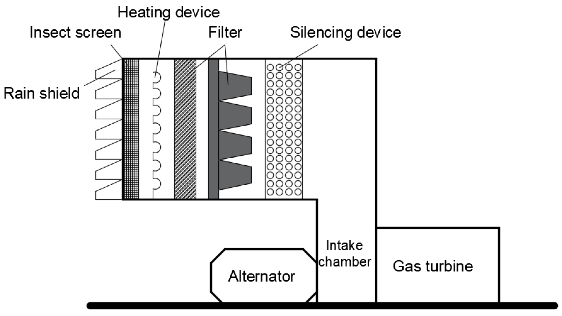
Figure 1 shows the gas turbine inlet filtration system that uses a conical filter. In this paper, the conical cartridge filter in the system is modeled and optimized, so as to improve the working efficiency of the gas turbine inlet filtration system.
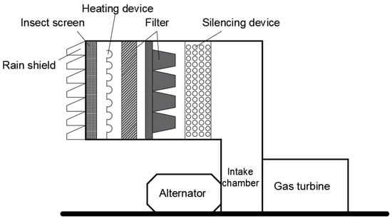
Figure 1.
Gas turbine intake filtration system.
As shown in Figure 2, the conical cartridge filter mainly consists of a filter chamber, a filter cartridge, a dust baffle, a filter cartridge plate, a clean air chamber, a pulse valve, a nozzle, and other parts. The cartridge filter has the following two working states: filtering state and cleaning state. Most of the time, the dust collector is in the state of positive blowing filtration: the filter gas with low wind speed flows out from the filter chamber through the filter cylinder and then through the clean air chamber. When the ash deposition on the side wall of the filter cartridge reaches the critical value, the pulse valve is opened for pulse cleaning. At this time, the filter cartridge is still filtering, but only a very small amount of gas enters the purge chamber through the side wall of the filter cartridge. The high-speed airflow is ejected from the nozzle, inducing a large amount of gas around to enter the filter cartridge together. After entering the interior of the filter cartridge, the dynamic pressure of the airflow is converted into static pressure, the filter cartridge expands and vibrates, and the dust attached to the side wall of the filter cartridge falls into the ash hopper. This is the “self-cleaning” process of the filter cartridge.
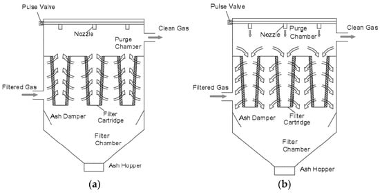
Figure 2.
Working status of filter cartridge dust collector. (a) Positive blowing filtration; (b) blowback cleaning.
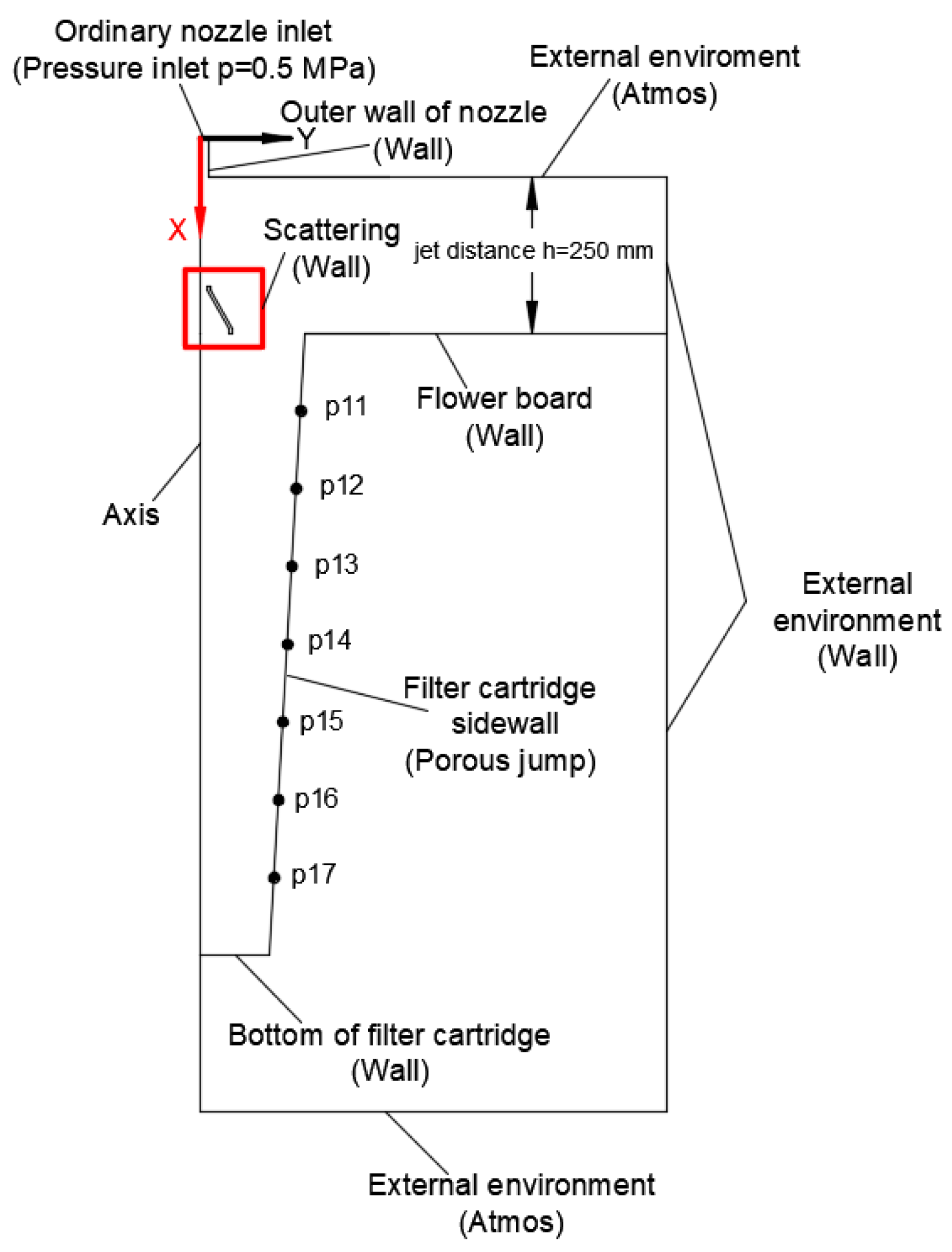
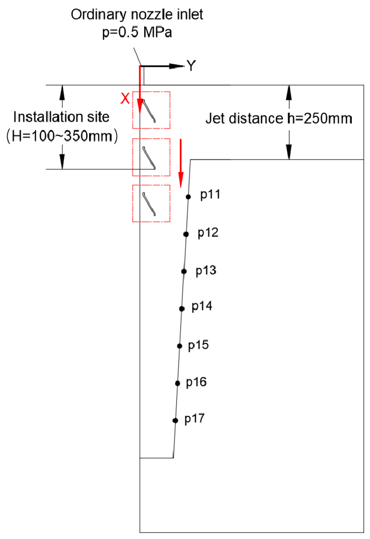
To establish a two-dimensional physical model of a conical filter cartridge dust collector and simplify the model for better application in CFD. The outlet of the pulse valve is simplified as the pressure inlet of the physical model, and only the pulse ash removal process of a group of filter cartridges and nozzles is considered. The ash removal gas is regarded as ideal gas, and the temperature change is not considered. Figure 3 plots a two-dimensional axisymmetric model and monitoring point selection location for the combination of the upper open scattering nozzle (hereinafter referred to as the scattering nozzle) and the conical filter cartridge for ash cleaning. The spraying distance is h = 250 mm (the distance from the normal nozzle outlet to the filter cartridge inlet), and the scattering nozzle outlet is placed on the same horizontal line as the filter cartridge inlet. The spraying time is 100 ms. We selected monitoring points every 100 mm along the side wall of the filter cartridge, which were p11~p17.

Figure 3.
Numerical model and monitoring points.
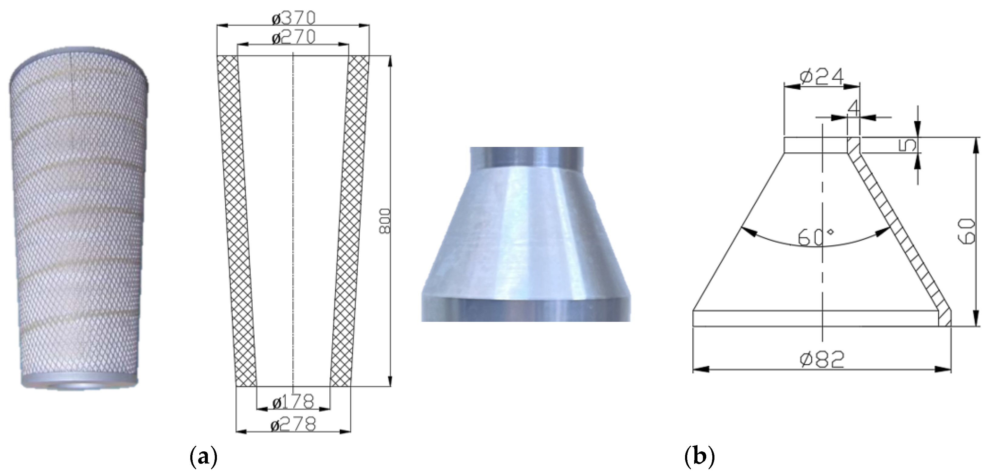
Figure 4 displays the physical appearance and specific dimensions of the conical filter cartridge and scattering nozzle. The inlet inner diameter of the conical filter cartridge is 270 mm, the bottom inner diameter is 178 mm, the thickness is 50 mm, and the length is 800 mm. The upper inlet diameter of the scattering nozzle is 16 mm, the lower outlet diameter is 74 mm, the nozzle height is 60 mm, and the opening taper is 60°.
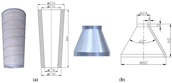
Figure 4.
(a) Size of a conical filter cartridge; (b) Size of a scattering nozzle.
ICEM is used to mesh the 2D structure grid. Inside the cylindrical nozzle, the longitudinal and radial grid size is about 1 mm. Inside the filter cartridge, the longitudinal and radial grid size is about 2 mm. Inside the scattering nozzle, 65 nodes are taken vertically, and 20 nodes are taken radially. The boundary layer is drawn on the side wall of the nozzle, the side wall of the filter cartridge, and the outer wall of the scattering nozzle. The boundary layer is taken as 0.1~0.3 mm, and the growth rate is set to 1.2. The number of grid cells is 149,379. When the grid quality is determined by the Determinant 2 × 2 × 2, the worst grid quality is 0.871. In total, 99% of the mesh quality is between 0.95 and 1, and the mesh quality is good, which meets the requirements of numerical simulation.
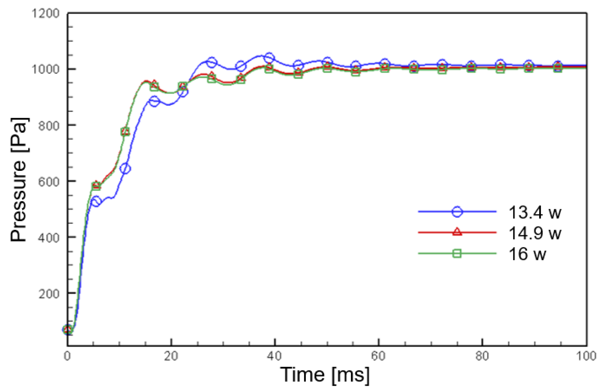
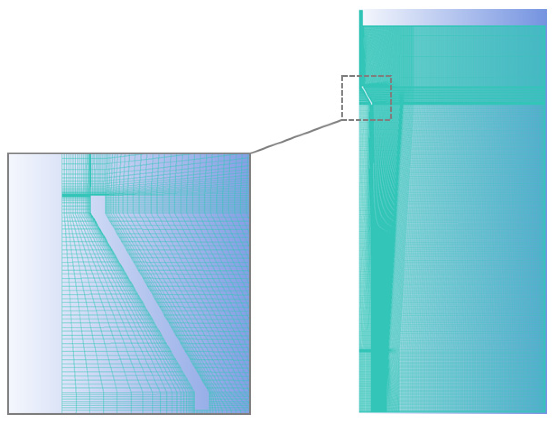
To verify grid independence, the grid is encrypted. As shown in Figure 5, it is the pressure at the p 15 monitoring point of the three models with different numbers of grids. In the case of 14.9 w and 16 w grids, the pressure changes at the same monitoring point are almost coincident. Therefore, it can be considered that the grid of 14.9 w has met the requirement of grid independence and is adopted in this paper. Figure 6 shows the overall effect of meshing and the meshing around the scattering nozzle. Under the conditions of this grid, the peak pressures of the monitoring points p 11, p 14, and p 15 are 769.8 Pa, 922.6 Pa, and 1244.3 Pa. It is basically consistent with the experimental results of Liu et al. [37] using a 59° diffuser and a spraying distance of 210 mm, so it is considered that the grid is realistic.
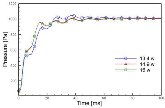
Figure 5.
Pressure curves of p 15 monitoring points in different grids.
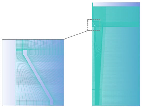
Figure 6.
Mesh division details.
2.2. Solution Method and Boundary Conditions
Pressure-inlet and pressure-outlet boundary conditions are used. The inlet of the normal nozzle is the pressure inlet boundary (p = 0.5 MPa). The external environment at the top and bottom of the model is set as the pressure outlet (p is atmospheric pressure). The turbulence intensity I and the hydraulic diameter DH are used as the transport scalar values, where the nozzle DH = 20 mm. Equation (1) is shown as follows:
where u′ denotes the velocity pulse quantity, uavg is the average velocity, and DH is the hydraulic diameter.
There is no relative motion on the wall in the pulse jet model of the conical filter cartridge. The wall is set as a solid wall and a non-slip boundary condition is adopted. The simplified model of the pulse jet of a conical filter cartridge is rotating geometry. In FLUENT, the axis of rotating geometry can be set as an axis boundary condition, and the two-dimensional simulation of a three-dimensional situation can be used. The side wall of the filter cartridge is set as a porous jump boundary condition, defined by Darcy’s law, and an additional inertia loss, as shown in Equation (2):
where μ denotes laminar viscosity; α is the permeability; v represents normal velocity; ∆m is the thickness of the medium. The filter material used on the surface of the conical filter cartridge in this simulation ∆m = 0.6 mm.
The impulse injection process is a transient, compressible, unsteady in three-dimensions that follows the laws of mass, momentum, and energy conservation as outlined in Equations (3)–(7) [38]. The transient solver is applied in Fluent, and the solution time is 0.1 s, the time step set to 0.0002 s. Coupled algorithm and realizable k-ε model are selected to describe the pulse cleaning process.
Mass-conservation equation:
Momentum conservation equation:
Energy conservation equation:
where ρ denotes density; t is time; is the velocity vector; u, v, and w are the in x, y and z directions. , etc. are the components of the viscous stress acting on the surface of the microelement; CP is the specific heat capacity; T is temperature; K is the heat transfer coefficient of the fluid; ST is the internal heat source of the fluid and the part of the fluid mechanical energy converted into heat energy due to viscous action.

Table 1.
Boundary conditions and parameter settings.
Table 2.
Calculation model and settings.
3. Results and Discussion
3.1. Dynamic Analysis of Pulse Cleaning with Conical Filter Cartridge
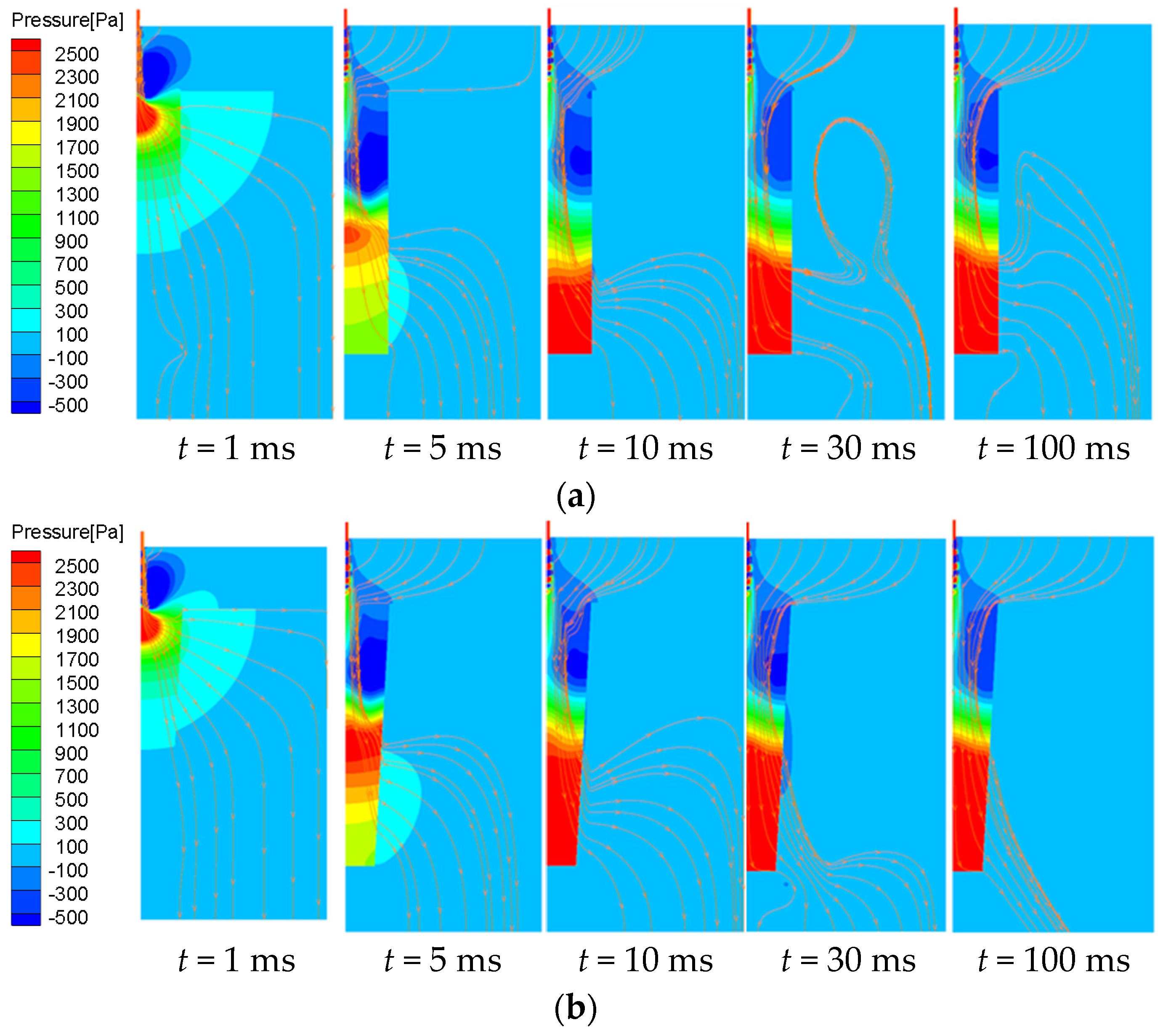
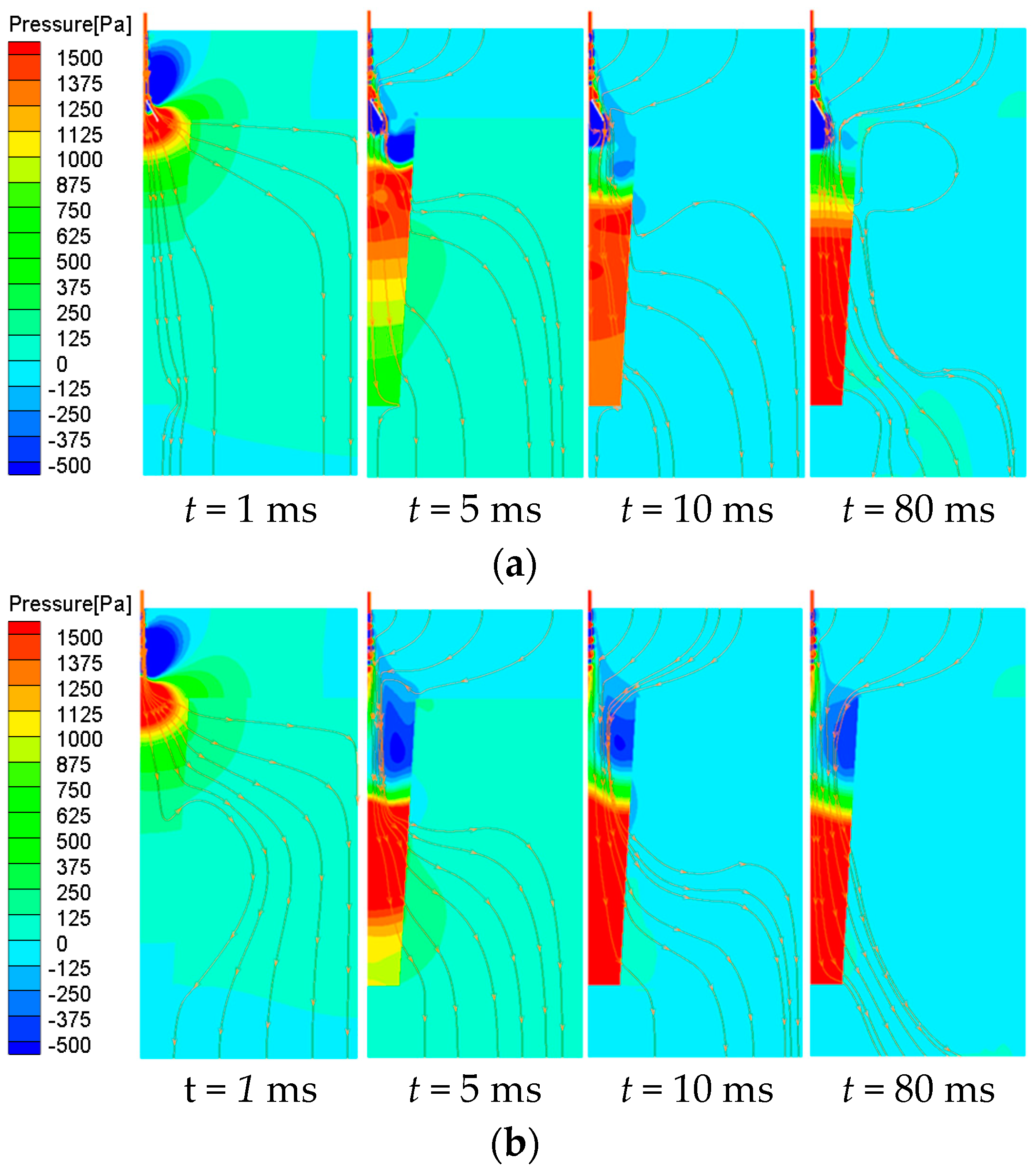
The pressure and streamline distribution of the cylindrical filter cartridge and the conical filter cartridge are shown in Figure 7. In this working condition, normal nozzles are used, the injection pressure is 0.5 MPa, and the injection distance is 200 mm.
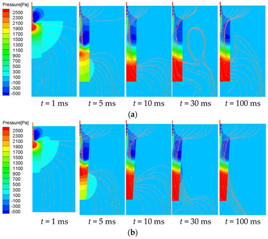
Figure 7.
Pressure and streamline distribution diagram inside the filter cartridge. (a) Pulse cleaning combination of normal nozzle and cylindrical filter; (b) pulse cleaning combination of normal nozzle and conical filter cartridge.
As shown in Figure 7, compared to cylindrical filter cartridges, conical filter cartridges exhibit a higher internal pressure and a more prominent pressure accumulation effect, especially in the middle and lower parts of the filter cartridge. This is due to the smaller space inside the conical filter cartridge (especially in the middle and lower parts). When the air intake in the filter cartridge is similar, the gas is more likely to accumulate upward, and more airflow dynamic pressure is converted into static pressure conducive to ash removal. When the cleaning is in a stable state (t = 100 ms), the airflow in the conical filter cartridge flows out along the middle and lower parts of the filter cartridge, and some airflow in the cylindrical filter cartridge has a tendency to form a vortex outside the filter cartridge. This vortex formation leads to cleaning resistance in localized areas that ultimately affects the pulse cleaning effect.
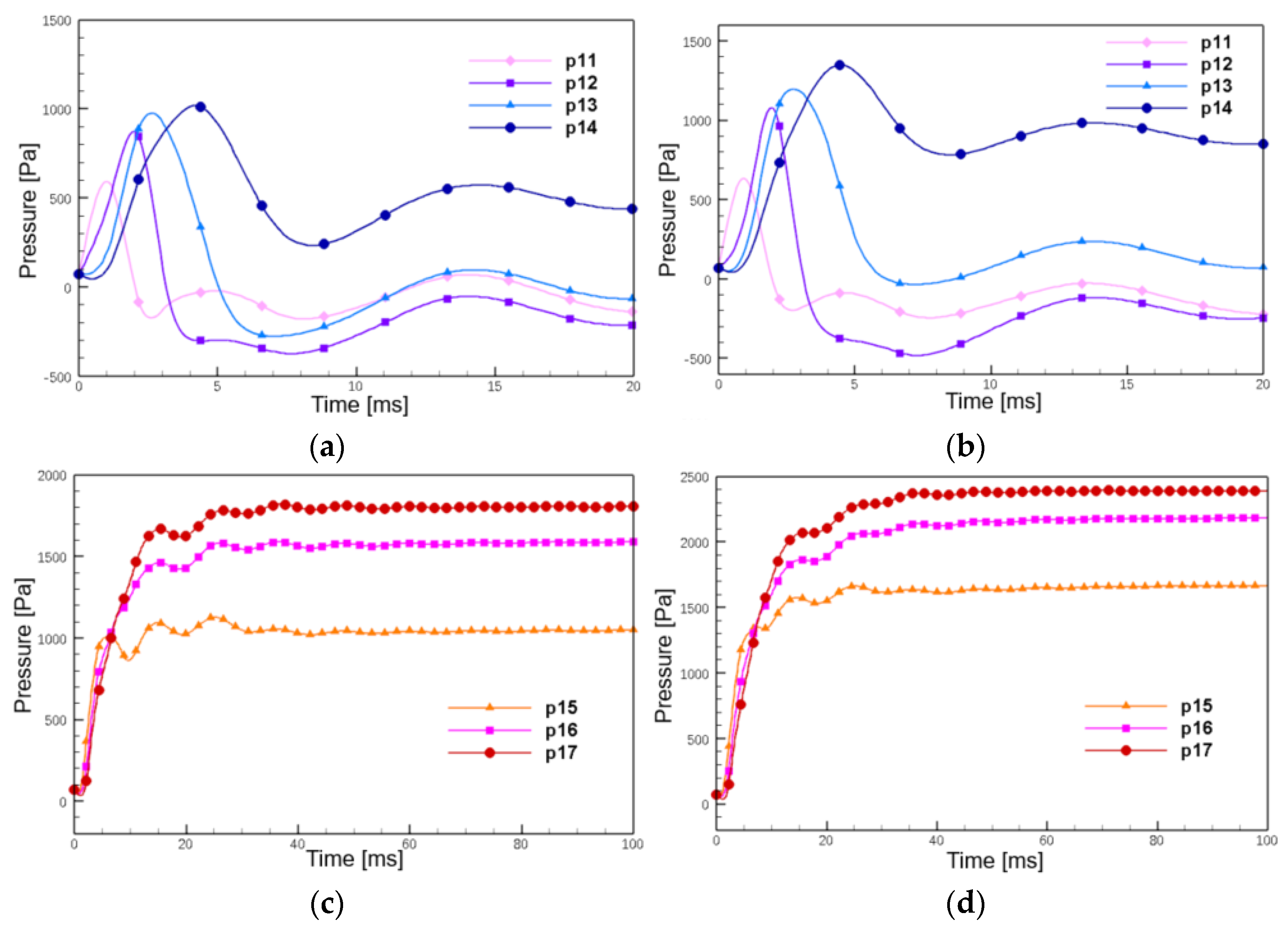
As shown in Figure 8, it is the pressure curve of the side wall of the filter cartridge. It can be seen that the pressure peak in the middle and upper part of the filter cartridge is formed when the pulse airflow reaches the side wall of the filter cartridge for the first time, and the formation period is the initial stage of pulse cleaning. The pressure peak in the lower part of the filter cartridge is formed by pressure accumulation, and the formation period is in the latter part of the pulse cleaning; however, the upper part of the filter cartridge always has insufficient dust removal. In the following research, in order to improve the dust removal strength of the upper part of the filter cartridge, the airflow that reaches the upper part of the filter cartridge for the first time should be larger. And the direction of the airflow should be more vertical on the side wall of the filter cartridge.
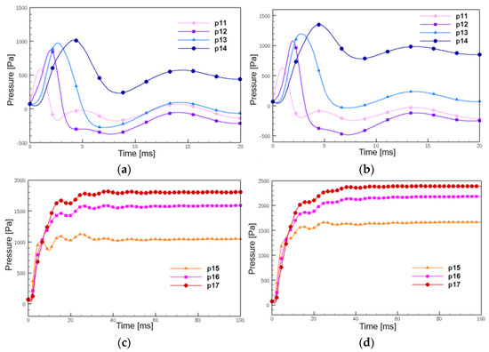
Figure 8.
Side wall pressure curve of filter cartridge. (a,c) Normal nozzle and cylindrical filter cartridge. (b,d) Normal nozzle and conical filter cartridge.
The performance of the pulse injection of the filter cartridge is expressed by the injection intensity and injection uniformity [39], in which the average value of the pressure peak at different monitoring points on the side wall of the filter cartridge is expressed as pulse injection intensity, and the index of injection uniformity is expressed as KP [40]. The smaller the KP, the more uniform the pressure peak distribution on the side wall of the filter cartridge and the better the ash removal performance [41]. Equations (8)–(10):
Table 3 lists the pressure peaks of each monitoring point when the normal nozzle is combined with a cylindrical or conical filter cartridge. It is calculated from Table 3 and Equation (10) that the injection intensity is 1140.7 Pa when the normal nozzle and the cylindrical filter cylinder are combined. The injection intensity is 1499.4 Pa when the normal nozzle and the conical filter cylinder are combined. When the conical filter cartridge is used, the injection intensity is increased by 1.31 times.
Table 3.
The pressure peak of each measuring point of cylindrical filter cylinder and conical filter cylinder.
It is calculated from Table 3 and Equations (9) and (10) that the injection uniformity index KP is 0.31 when the normal nozzle is combined with the cylindrical filter cartridge. When the normal nozzle is combined with the conical filter cartridge, KP is 0.38. When the conical filter cartridge is used, KP is increased by 1.2 times.
In summary, it can be seen that the cleaning intensity can be improved when the conical filter cartridge is used for pulse cleaning, but the cleaning uniformity is reduced.
3.2. Synergistic Effect of Scattering Nozzle and Conical Filter Cartridge
When the conical filter cartridge was combined with the normal nozzle, we changed the injection pressure and injection distance. The best working condition was the following: injection pressure p = 0.5 MPa, injection distance h = 250 mm. For this condition with conical cartridge, we added the diffuser nozzle.
As shown in Figure 9, the pulse cleaning cloud diagram of the conical filter cartridge with and without the scattering nozzle. The negative pressure area in the upper part of combination A is significantly reduced, indicating that the diversion and flow guide of the scattering nozzle can make the pulse gas act more on the upper area of the filter cartridge, and achieve the effect of improving the cleaning performance of the conical filter cartridge.
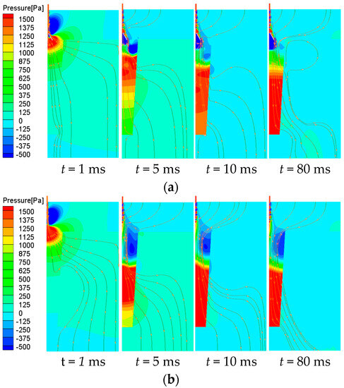
Figure 9.
Dynamic cloud picture of pulse cleaning with conical filter cartridge. (a) Pulse cleaning combination A of the scattering nozzle and conical filter cartridge; (b) pulse cleaning combination B of normal nozzle and conical filter cartridge.
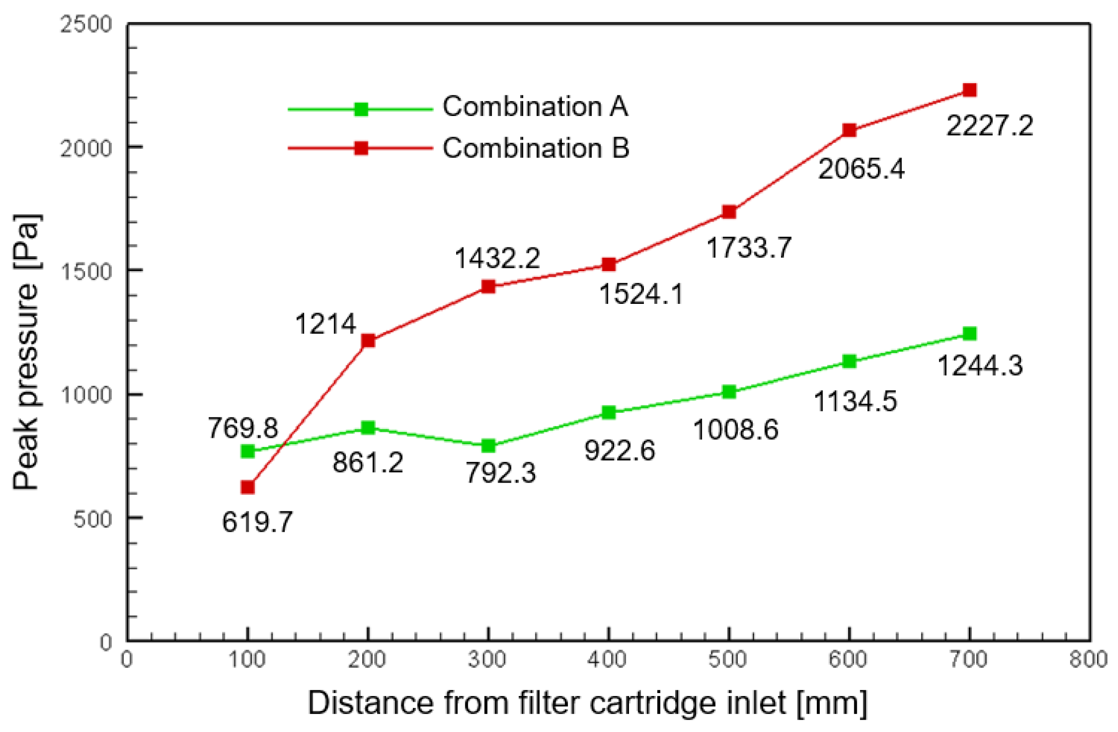
Quantitative analysis of pulse cleaning performance of conical filter cartridges with the scattering nozzle installed from peak pressure. As shown in Figure 10, the pressure peak of the p11 monitoring point of the A combination is 769.8 Pa, and the pressure peak of the B combination is 619.7 Pa. The pressure peak of the upper side wall of the filter cartridge increases by 1.24 times. The pressure peak at the p 17 monitoring point at the lower part of the filter cartridge of the A combination is 1244.3 Pa, and the pressure peak at this point of the B combination is 2227.2 Pa. The pressure peak at the lower part of the filter cartridge is reduced by 1.79 times.
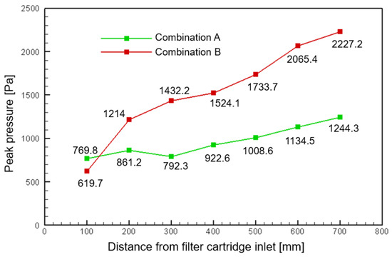
Figure 10.
Axial distribution of sidewall pressure peak under two working conditions.
From the trend of the pressure peak curve, the A combination is relatively flat, and the B combination curve is steep, indicating that the installation of the scattering nozzle under the normal nozzle can effectively improve injection uniformity. It is calculated that the injection uniformity index KP decreases to 0.17 after the installation of the scattering nozzle, while the injection uniformity index KP is 0.32 in the case of only the normal nozzle. The installation of the scattering nozzle increases the uniformity of the cleaning inside the filter cartridge by nearly double.
3.3. Optimum Installation Position of Scattering Nozzle
In order to further explore the influence of the installation position of the scattering nozzle on the pulse cleaning effect of the conical filter cartridge, we established several sets of numerical models for comparison. The parameter selection values are shown in Table 4. As shown in Figure 11, the installation position of the scattering nozzle changes from the outside of the filter cartridge to the inlet of the filter cartridge (H = 250 mm), and finally enters the inside of the filter cartridge.
Table 4.
Parameter selection.
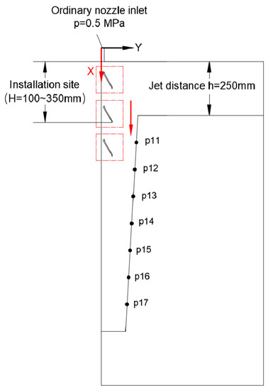
Figure 11.
Variation in the installation position of scattering nozzle.
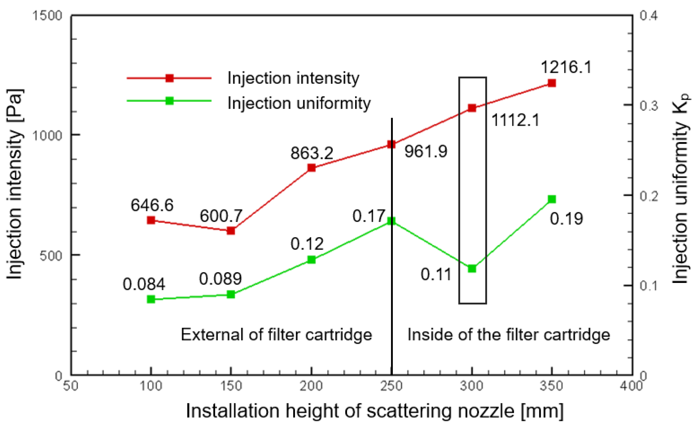
As shown in Figure 12, the overall injection intensity curve shows a trend of rapid rise first and then slow rise. This is because when the distance between the scattering nozzle and the filter cartridge increases, its entrainment effect on the external gas gradually weakens, and the air intake of the filter cartridge no longer increases significantly. In engineering, the overall injection intensity can be improved by adding the scattering nozzle with a higher installation height.

Figure 12.
Pulse cleaning performance of scattering nozzles at different installation heights.
The injection uniformity index KP shows a trend of increasing first, then decreasing, and then continuing to rise, indicating that there is an optimal installation position for injection uniformity. When H = 300 mm, the inlet of the scattering nozzle is just parallel to the inlet of the filter cartridge. Because a greater blowing intensity and a smaller KP mean better cleaning performance, at this time, the injection uniformity is 0.11, and the injection intensity is also at a large value, which can optimize the pulse cleaning performance of the conical filter cartridge to the greatest extent. The peak pressure of each monitoring point is 893.7 Pa, 1151.3 Pa, 1046.1 Pa, 1015.9 Pa, 1125.3 Pa, 1233.1 Pa, and 1319.4 Pa.
4. Conclusions
In this paper, a numerical model of the pulse cleaning of a conical cartridge filter is established, and the pulse cleaning performance of a conical cartridge filter is studied by CFD. Compared to the state-of-art methods, including Zhu et al. [32] and Wang et al. [33], Zhu et al. found that the injection intensity of the upper part of the combined conical filter cartridge was sufficient, but the blowing strength of the lower part was insufficient. Wang et al. installed a scatting nozzle on cylindrical filter cartridges to reduce KP to 0.16. This paper proposes a new strategy to improve the cleaning performance of conical filter cartridges by using the scattering nozzle. And the optimal installation position of the scattering nozzle is studied. The conclusion is drawn as follows:
- (1)
- The numerical simulation reveals that the accumulation of pressure inside the conical filter cartridge is more obvious when applying normal nozzles. Although the injection strength of conical filter cartridge is better than that of the cylindrical filter cartridge, the injection uniformity needs to be improved;
- (2)
- The scattering nozzle is installed under the normal nozzle to improve the cleaning effect with the conical filter cartridge. The results denote that, compared to the pulse cleaning combination lacking a scattering nozzle, the injection uniformity KP decreased from 0.32 to 0.17, the injection uniformity increased by nearly double, and the cleaning intensity satisfied the cleaning demand;
- (3)
- The influence of the installation position of the scattering nozzle on the cleaning effect was studied. The results denote that the cleaning performance of the conical filter can be optimized to the greatest extent when the scattering nozzle is parallel to the inlet of the conical filter. At this time, the injection uniformity is 0.11, and the upper and lower parts of the conical filter can ensure the cleaning power (higher than 600 Pa).
The above conclusions provide a solution for enterprises to optimize the cleaning effect of the conical filter cartridges and improve the work efficiency of gas turbine intake filtration systems.
Finally, here in this paper, numerical simulations were conducted to validate the effectiveness and superiority of the proposed approach, and they achieved pretty good results. But still, the future work of our research will focus on the experimental verification of the proposed combination of the conical filter cartridges and the scattering nozzle approach under practical scenarios.
Author Contributions
Conceptualization, J.D. and W.B.; methodology, J.Y. and J.D.; software, J.D.; formal analysis, R.Y. and J.D.; investigation, J.D. and X.R.; resources, J.Y.; data curation, J.D.; writing—original draft preparation, J.D.; writing—review and editing, J.D. and R.Y.; visualization, J.Y. and J.D.; supervision, J.Y. and R.Y.; funding acquisition, J.Y. All authors have read and agreed to the published version of the manuscript.
Funding
This research work was supported by Natural Science Foundation Innovation Group Program of Hubei Province under Grant No. 2020CFA033, China Postdoctoral Science Foundation under Grant No. 2020M682492, and the 14th Five Year Plan Hubei Provincial Advantaged Characteristic Disciplines (Groups) Project of Wuhan University of Science and Technology under Grant No. 2023B0301, which are greatly appreciated.
Institutional Review Board Statement
Not applicable.
Informed Consent Statement
Not applicable.
Data Availability Statement
The data in the current study are not publicly available for legal/ethical reasons but are available from the corresponding author on reasonable request.
Acknowledgments
The authors also gratefully acknowledge the helpful comments and suggestions of the reviewers, which have improved the presentation.
Conflicts of Interest
The authors declare no conflict of interest.
References
- Naylor, A.W.; Ford, J. Vulnerability and loss and damage following the COP27 of the UN framework convention on climate change. Reg. Environ. Chang. 2023, 23, 38. [Google Scholar] [CrossRef]
- Zeng, L.; Long, W.; Li, Y. A novel method for gas turbine condition monitoringbased on KPCA and analysis of statistics T2 and SPE. Processes 2019, 7, 124. [Google Scholar] [CrossRef]
- Talal, W.; Akroot, A. Exergoeconomic analysis of an integrated solar combined cycle in the Al-Qayara power plant in Iraq. Processes 2023, 11, 656. [Google Scholar] [CrossRef]
- Shu, G.; Yu, C.; Shen, G. Research on development of heavy gas turbines in China in new period. J. Eng. Sci. 2022, 24, 184–192. [Google Scholar]
- Poullikkas, A. An overview of current and future sustainable gas turbine technologies. Renew. Sustain. Energy Rev. 2005, 9, 409–443. [Google Scholar] [CrossRef]
- Walsh, P.P.; Fletcher, P. Gas Turbine Performance; John Wiley & Sons: Hoboken, NJ, USA, 2004. [Google Scholar]
- Wilcox, M.; Kurz, R.; Brun, K. Technology review of modern gas turbine inlet filtration systems. Int. J. Rotating Mach. 2012, 2012, 128134. [Google Scholar] [CrossRef]
- Jeong, K.; Jungho, H.; Hyun, C. Effective filtration area of a pleated filter bag in a pulse-jet bag house. J. Powder Technol. 2017, 31, 522–527. [Google Scholar]
- Ushio, M. Use of a filter cartridge combined with intra-cartridge bead-beating improves detection of microbial DNA from water samples. J. Methods Ecol. Evol. 2019, 10, 1142–1156. [Google Scholar] [CrossRef]
- Wakeman, R.J.; Hanspal, N.S.; Wanghode, A.N.; Nassehi, V. Analysis of pleat crowding and medium compression in pleated cartridge filters. Chem. Eng. Res. Des. 2005, 83, 1246–1255. [Google Scholar] [CrossRef]
- Li, J.; Wang, P.; Wu, D. Numerical study of opposing pulsed-jet cleaning for pleated filter cartridges. J. Sep. Purif. Technol. 2020, 234, 116086. [Google Scholar] [CrossRef]
- Lo, L.; Hu, S.; Chen, D. Numerical study of pleated fabric cartridges during pulse-jet cleaning. J. Powder Technol. 2010, 198, 75–81. [Google Scholar] [CrossRef]
- Li, H.; Choi, J.; Li, B. Numerical analysis on the gas flow dynamics from a rectangular slot-nozzle for pulse cleaning of filter unit. J. Powder Technol. 2016, 297, 330–339. [Google Scholar] [CrossRef]
- Chen, S.; Wang, Q.; Chen, D. Effect of pleat shape on reverse pulsed-jet cleaning of filter cartridges. J. Powder Technol. 2017, 305, 1–11. [Google Scholar] [CrossRef]
- Yan, C.; Liu, G.; Chen, H. Effect of induced airflow on the surface static pressure of pleated fabric filter cartridges during pulse jet cleaning. J. Powder Technol. 2013, 249, 424–430. [Google Scholar] [CrossRef]
- Yuan, N.; Ren, L.; Wang, B. Experimental study on the effects of diversion device on pulse-jet cleaning of horizontal filter cartridge. J. Process Saf. Environ. Prot. 2021, 145, 247–254. [Google Scholar] [CrossRef]
- Li, J.; Wu, D.; Wu, Q. Design and performance evaluation of novel colliding pulse jet for dust filter cleaning. J. Sep. Purif. Technol. 2019, 213, 101–113. [Google Scholar] [CrossRef]
- Li, S.; Zhou, F.; Xie, B. Influence of injection pipe characteristics on pulse-jet cleaning uniformity in a pleated cartridge filter. J. Powder Technol. 2018, 328, 264–274. [Google Scholar] [CrossRef]
- Xie, B.; Pang, J.; Hu, S. A new method to improve the pulse-jet cleaning performance of filter cartridges and its application to dust control in underground coal mines. J. Powder Technol. 2012, 405, 117528. [Google Scholar] [CrossRef]
- Zhang, Q.; Yuan, R.; Lv, Y.; Li, Z.; Wu, H. Multivariate dynamic mode decomposition and its application to bearing fault diagnosis. IEEE Sens. J. 2023, 23, 7514–7524. [Google Scholar] [CrossRef]
- Yuan, R.; Lv, Y.; Xu, S.; Li, L.; Kong, Q.; Song, G. ResNet-integrated very early bolt looseness monitoring based on intrinsic feature extraction of percussion sounds. Smart Mater. Struct. 2023, 32, 034002. [Google Scholar] [CrossRef]
- Lv, Y.; Yuan, R.; Song, G. Multivariate empirical mode decomposition and its application to fault diagnosis of rolling bearing. Mech. Syst. Signal Process. 2016, 81, 219–234. [Google Scholar] [CrossRef]
- Yuan, R.; Lv, Y.; Wang, T.; Li, S.; Li, H. Looseness monitoring of multiple M1 bolt joints using multivariate intrinsic multiscale entropy analysis and Lorentz signal-enhanced piezoelectric active sensing. Struct. Health Monit. 2022, 21, 2851–2873. [Google Scholar] [CrossRef]
- Yuan, R.; Lv, Y.; Lu, Z.; Li, S.; Li, H. Robust fault diagnosis of rolling bearing via phase space reconstruction of intrinsic mode functions and network under various operating conditions. Struct. Health Monit. 2023, 22, 846–864. [Google Scholar] [CrossRef]
- Zhang, A.; Yu, D.; Zhang, Z. TLSCA-SVM fault diagnosis optimization method based on transfer learning. Processes 2022, 10, 362. [Google Scholar] [CrossRef]
- Wang, Y.; Ren, W.; Liu, Z.; Li, J.; Zhang, D. T-S fuzzy model-based fault detection for continuous stirring tank reactor. Processes 2021, 9, 2127. [Google Scholar] [CrossRef]
- Xie, B.; Yan, Z.; Du, Y.; Zhao, Z.; Zhang, X. Determination of holmquist–johnson–cook constitutive parameters of coal: Laboratory study and numerical simulation. Processes 2019, 7, 386. [Google Scholar] [CrossRef]
- Zhang, Q.; Chen, H.; Ju, M.; Chen, J. Experimental study on improving pulse ash cleaning effect of filter cylinder by induced nozzle. J. Environ. Eng. 2012, 30, 62–65+138. [Google Scholar]
- Yan, C.; Zhang, M.; Lin, L.; Chen, H. An analysis of a reverse pulse cleaning process using high-flow pleated fabric filter cartridges. J. Process Saf. Environ. Prot. 2018, 113, 264–274. [Google Scholar]
- Chen, S.; Chen, D. Numerical study of reverse multi-pulsing jet cleaning for pleated cartridge filters. J. Aerosol Air Qual. Res. 2016, 16, 1991–2002. [Google Scholar] [CrossRef]
- Su, Z.; Lin, Z.; Li, J. Numerical simulation of improving the cleaning performance of gold cone filter cylinder by pulse spraying with Venturi nozzle. Chin. J. Environ. Eng. 2022, 16, 220–229. [Google Scholar]
- Gao, D.; Zhou, G.; Yang, Y. Design of pulse cleaning device for single-filter cartridge dust collector by multi-factor orthogonal method based numerical simulation. Powder Technol. 2021, 391, 494–509. [Google Scholar] [CrossRef]
- Wu, Q.; Xie, W.; Chen, J. Effect of annular baffles on the pulsed-jet performance of dust filter cartridge regeneration. Powder Technol. 2023, 421, 118450. [Google Scholar] [CrossRef]
- Wang, B. Application of fluid simulation technology in nozzle flow field analysis. Chin. J. Mach. Ind. Stand. Qual. 2019, 5, 35–39. [Google Scholar]
- Zhu, Y.; Zuo, D.; Yang, X. Numerical simulation study on pulse back-blowing cleaning process of combined filter cartridge. Fluid Mach. 2020, 48, 23–28. [Google Scholar]
- Wang, S.; Liu, D.; Yu, H. Analysis of dynamic characteristics of pulse flow field and cleaning pressure based on scattering structure. Chin. J. Environ. Eng. 2021, 39, 89–95. [Google Scholar]
- Liu, D.; Yu, H.; Wang, L. Experiment on improving pulse injection cleaning performance by upper open diffuser. Chin. J. Environ. Eng. 2019, 37, 138–142. [Google Scholar]
- Zhang, Q.; Liu, D.; Wang, M. Characteristics and evaluation index of pulse-jet dust cleaning of filter cartridge. J. Process Saf. Environ. Prot. 2022, 157, 362–374. [Google Scholar] [CrossRef]
- Li, J.; Chen, Y.; Lin, Z. Research progress and prospect of pulse spray dust cleaning technology of dust removal filter. J. Met. Mine 2022, 51, 23–35. [Google Scholar]
- Li, T.; Qi, S.; Huang, S. Comparison and application of evaluation index of flow field velocity distribution uniformity. J. Therm. Power Gener. 2013, 42, 60–63+92. [Google Scholar]
- Chen, Q.; Lin, Z.; Li, J. Numerical simulation of diffusion nozzles improving the performance of pulse spray cleaning of gold cone filter cartridges. Chin. J. Environ. Eng. 2021, 15, 1634–1644. [Google Scholar]

Disclaimer/Publisher’s Note: The statements, opinions and data contained in all publications are solely those of the individual author(s) and contributor(s) and not of MDPI and/or the editor(s). MDPI and/or the editor(s) disclaim responsibility for any injury to people or property resulting from any ideas, methods, instructions or products referred to in the content. |
© 2023 by the authors. Licensee MDPI, Basel, Switzerland. This article is an open access article distributed under the terms and conditions of the Creative Commons Attribution (CC BY) license (https://creativecommons.org/licenses/by/4.0/).