Article

Research on Classified Treatment of Electrolytic Zn Anode Slime Based on μ-XRF and Cluster Heatmap

1
School of Materials Science and Engineering, Anhui University of Science &Technology, Huainan 232001, China
2
State Key Laboratory of Pollution Control and Resource Reuse, College of Environmental Science and Engineering, Tongji University, Shanghai 200092, China
3
School of Environmental Science & Engineering, Tianjin University, Tianjin 300350, China
*
Author to whom correspondence should be addressed.
Processes 2023, 11(9), 2585; https://doi.org/10.3390/pr11092585
Submission received: 29 July 2023 / Revised: 25 August 2023 / Accepted: 27 August 2023 / Published: 29 August 2023

Abstract

:
The purpose of this research is to have a clearer understanding of the resource value of electrolytic Zn anode slime, explore its fine structure and treat it in a classified manner. In this paper, the composition, content and distribution of Pb, Mn and Zn in electrolytic Zn anode slime during one production cycle were studied under typical working conditions of enterprises, by using the method of μ-XRF combined with mm-XRF. Based on heatmap and cluster analysis, the resource value of anode slime at different points in the electrolytic Zn silting area and the conventional area was evaluated. The research results were as follows: (1) There were two different areas of electrolytic Zn anode slime: the silting area and conventional area. Between these, the silting area accounted for approximately 15% of the total number of anode plates, and there were significant differences between these areas in terms of surface element content, surface morphology, slime thickness and water content. (2) In the silting area, 3.9 mm away from the Pb-based anode plate surface, there were lumps with fluorescence counting intensity that was close to that of pure Pb. (3) Anode slime at a thickness of 0.1 mm in the silting area could be classified as a type of resource. The resource attributes were categorized using a complete-linkage algorithm and the actual demand of Zn hydrometallurgy enterprises for recycling anode slime from the leaching process, for those with ≥45% Mn content and <20% Pb content. High-Pb resources include 0–1.5 mm (CAP), 0–1.4 mm (SAP) and 6.3–7.0 mm (SAP). A low-Pb, high-Mn and high-Zn resource was identified at 2.9–6.0 mm (SAP). Low-Pb, high-Mn and low-Zn resources include 1.6–6.0 (CAP), 1.5–2.8 mm (SAP) and 6.1–6.2 mm (SAP).

1. Introduction

The production of Zinc (Zn), a common non-ferrous metal that is used extensively in anti-corrosion cladding and the smelting of Zn-containing alloys, is enormous, with 85% of that capacity coming from Zn hydrometallurgy [1]. High acidity and strong oxidative electrolyte environment require high demands on the anode material. Lead (Pb) is an irreplaceable anode material in the electrolytic extraction of Zn [2], and a large amount of anode slime (containing PbSO4) is generated by the Pb-based anode in the electrolytic process [3]. Based on an annual production of 6 million tons of Zn, it is estimated that this would result in 110,000 tons of Pb leaching, accompanied by the Please check that the intended meaning is retained.generation of 300,000 tons of anode slime, a hazardous waste which will not only cause waste of raw resources, but also pollute Zn products, thus affecting the production efficiency of enterprises [4,5]. In addition, anode slime contains heavy metal Pb, which can increase the risk of Pb entering the blood cirulatory system and causing damage to the kidney, liver and nerve tissue [6,7,8]. Therefore, electrolytic Zn anode slime with high Pb content is the top priority in the prevention and control of heavy metal pollution, as evidenced by the stricter relevant laws and regulations in recent years [9].
In the process of Zn hydrometallurgy, heavy metal anode slime mainly comes from the oxidation of divalent manganese (Mn) ions on the anode surface of Pb-based alloys, resulting in an anode slime attached to the plate surface. The competitive mechanisms of oxygen evolution reaction and Mn2+ oxidation causes the anode slime to grow and destroy repeatedly [10], which not only makes the physical and chemical morphology of the anode slime on the plate surface complicated, but also forms a large number of suspended substances (SSs) in the electrolyte. Due to its poor conductivity, the accumulation of anode slime on the plate surfaces leads to an increase of bath voltage. This requires regular cleaning of anodes and electrolysis cells, greatly increasing labor intensity and reducing normal production time [11]. In addition, excessive anode slime may cause short-circuit inductance corrosion of cathodes [12], suspended anode slime particles that may also affect the formation of Zn silt on cathodes [13,14] and high-Pb pollution of Zn products. The formation mechanism of high-Pb anode slime is still inconclusive in academic circles because of the differences in experimental conditions. However, it is certain that MnO2, the main component of anode slime, is suspended in the electrolytic bath, and part of the accumulation essence comes from the anode slime on the plate surface and the Pb essence in anode slime comes from the Pb anode plate. At present, while Zn hydrometallurgy enterprises in China annually produce 1 ton of Zn on average, 40–50 kg of anode slime containing about 10% Pb will enter the electrolysis system. Typically, the collected anode slime is reused in the leaching process [15]. Morphology and composition analyses of anode slime on the plate surface are keys for the resource utilization of Pb-containing anode slime.
There is no recognized chemical description in academic circles for the heterogeneous and complex Pb-containing porous layer or the impurities formed on the anode surface [16]. In the process of industrial production, the source of anode slime cannot be accurately classified [17], but in the research of this topic, academic circles believe that the chemical reactions on the anode surface of Zn electrolysis have a defined sequence that can inform classification. At the initial stage of electrolysis, the oxide layer of anode is mainly composed of Pb compounds, and then Mn dioxide is gradually attached to it.The interlayer crack and brittleness of Mn dioxide causes the corrosion of the anode plate surface by electrolytes [18,19]. In the previous research, we found that the anode slime of industrial systems has a boundary inflection point for the content distributions of Pb and Mn, and we proposed a specific location range of the film-slime layer [20]. For the purpose of film preservation and slime removal, most of the elemental Pb can be retained on the original anode plate by using intelligent slime removal equipment according to the inflection point of the membrane slime interface. If there is a need for further evaluation and resource utilization of anode slime, and specifically, the relative elemental contents of Mn, Pb and Zn, the mechanism of anode slime formation on anode plates and the distribution law of elements and thickness should be researched.
For the purposes of facilitating cleaner production, this paper researched the growth of anode slime in one electrolysis cycle of an electrolytic Zn anode plate in the whole electrolysis cell under the factory conditions. Based on the physical and microscopic chemical morphologies, the growth and slime-formation processes of anode slime on the anode plate surface were distinguished. The resource values of both were evaluated, based on comparisons between the contents of Pb, Mn and Zn in anode slime and the slime thickness in both silting area (sedimentation of suspended substance) and conventional area (ion discharge deposition). This article provides a new approach for the efficient classification and reuse of anode slime in the wet-zinc refining process. Based on our reported individual concentrations of Pb, Mn, and Zn at different depths in the silting and conventional areas of the anode slime, these can be selectively scraped and treated separately, providing a basis for improving environmental and economic benefits.

2. Materials and Methods

2.1. The Zinc Production Process Conditions of Sampling Enterprises

In a single electrolysis cell, the cathode current density was 550–600 A/m2, cell voltage was 3.35–3.37 V, current efficiency was 90–92%, space between the electrodes was 75 mm, the electrolyte composition was 55 g/L of Zn2+, 5–8 g/L Mn2+ and 195 g/L of H2SO4 and the temperature in the electrolysis cell was 32 °C (the margin of error is plus or minus 3 °C). An anode plate (Pb/Ag (0.8%) alloy) and aluminum cathode were used. The anode slime removal cycle was 12 days.

2.2. Test Sample Collection and Test Method

2.2.1. Sampling

Electrolysis cells No. 1, 14 and 28 were selected from the liquid supply system of the same chute, with a total of 48 anode plates in each electrolysis cell (Figure 1a). The working conditions of the enterprise required that four pieces of slime be removed each day, i.e., the slime removal cycle was 12 days, and anode plates be electrolyzed for 1–12 days in the same electrolysis cell. Two parallel samples were taken from anode plates for each electrolysis day, and 72 samples were taken from three electrolysis cells. The whole plate was photographed and archived. The characteristic areas were observed microscopically at 160 times magnification, then photographed and archived. The thickness of the anode slime was measured by a vernier caliper. By using the X-MET8000 portable environmental protection heavy metal detector X-ray fluorescence spectrometer (Oxford Instrument Co., Ltd., Abingdon, UK), the contents of Pb, Mn and Zn were measured at five points in the same position on each anode plate (Figure 1b). Caliper (Huoto IP65) was used to measure the anode slime thickness at these five points.

2.2.2. Preparation of Sealant Samples

The preparation of anode slime samples using 32 kg of epoxy resin AB glue is shown in Figure 2. A mud-containing anode plate was obtained with a fully silted morphology from the inlet of Electrolysis cell #14. A proper amount of glue A was weighed with a balance, heated in an oven at 60 °C for about 10 min, and then taken out after bubbles disappeared. Glue B was weighed on the balance, and then mixed with glue A according to the mass ratio of 3:1. A piece of anode plate containing silted anode slime that had been electrolyzed for 12 days at the liquid inlet of the electrolysis cell was selected, lifted from the electrolysis cell to the open space, and suspended for a slime removal time equal to that used in the production process of the enterprise. The prepared epoxy resin was poured on the surface of the anode plate containing slime, wrapped with multi-layer PE plastic film, vacuumed with an air pump to make the anode slime evenly impregnate with the epoxy resin and left to stand for 48 h. It was cut and sampled when it was completely solidified.

2.2.3. μ-XRF and mm-XRF Tests

In this paper, Micro X-ray Fluorescence (μ-XRF) was used to analyze the samples of slime-containing anode wrapped and fixed by epoxy resin in situ in a nondestructive manner, and the micro-distribution of anode slime, based on the contents of Pb, Mn and Zn in silting area was discovered. The μ-XRF test was carried out by using the SSRF (BL15U1) hard X-ray microprobe beamline station.
Small pieces measuring 50 mm long, 20 mm wide and 10 mm thick were cut from the epoxy resin-sealed anode plate, and the corners were polished with sandpaper, which were the rinsed with deionized water for the μ-XRF test. Several groups of anode slime samples collected during the enterprise’s routine working conditions were examined with an X-ray fluorescence analyzer for millimeter-level data (mm-XRF). A large number of targeted data were reviewed for the qualitative conclusions of the μ-XRF test; thus, the three-dimensional spatial distributions of Pb, Mn and Zn elements in anode slime in the silting area of industrial system were completely recorded.
Five groups of parallel samples were taken from the large silting area. The sampling location can be found in Figure 2, and the specific dimensions of the sample are shown in Figure 3. Each sample was fed from the front and outside of the anode slime to polish the anode slime powder layer by layer. The powder from the plate surface was collected at this time until the Pb base was seen. The average number of polishing cycles per sample was 20 times. By using mm-XRF, the measurement method was set to the fundamental parameter (FP) method: the measurement time was 10 s, each sample was tested 3 times, the average value was taken and the relevant chart was drawn.

3. Results and Discussion

3.1. Analysis of Morphology and Element Distribution of Tested Anode Slime

The surface morphology, thickness record and surface Mn, Pb and Zn contents of the anode slime sampled from a production cycle of cathode Zn products in the factory were observed. The test results are shown in Figure 4, Figure 5, Figure 6 and Figure 7.
As can be seen from Figure 4, the thickness of the anode slime in Electrolysis cell No. 1 first increased, then decreased and then increased with increasing number of electrolysis days. It reached 5.67 mm on the 7th day, decreased to 3.79 mm on the 9th day and increased to 5.27 mm on the 12th day. The thickness of anode slime in Electrolysis cell No. 14 first increased along with time, quickly increased to 6.82 mm during the first 8 days and then gradually decreased to 4.05 mm on the 12th day. The trend of anode slime thickness over time in Electrolysis cell No. 28 was similar to that in Electrolysis cell No. 1; it quickly increased to 5.77 mm during the first 7 days, decreased to 2.99 mm on the 9th day and then increased to 4.81 mm on the 12th day. The anode slime of the anode plates of electrolysis cells in different areas of the same chute of the liquid supply system gradually thickened with increasing electrolysis time, and reached stability and its maximum value after 6–8 days. At this point, the relative balance between the self-weight and adhesion of the anode mud is disrupted, resulting in subsequent repeated growth and shedding phenomena.
Figure 5 shows that in Electrolysis cell No. 1, the Pb content in anode slime decreased from 11.1% on the 1st day to 8.17% on the 4th day, gradually increased to 14.56% on the 11th day, and then decreased to 9.07% on the12th day. In Electrolysis cell No. 14, the Pb content in anode slime increased rapidly to 12.75% in the first 3 days, and then it generally remained at 9–10%, except for on the 11th day, when it reached 11.56%. In Electrolysis cell No. 28, the Pb content had no obvious fluctuations with time, and remained at 8–10%.
Figure 6 shows that in Electrolysis cell No. 1, the Mn content in anode slime rapidly increased to 71.39% during the first 5 days, and then fluctuated between 55% and 71%. In Electrolysis cell No. 14, the Mn content in anode slime gradually increased to 70.88% during the first 6 days, and then decreased gradually, except on the 10th day. In Electrolysis cell No. 28, the Pb content was stable at first and then decreased gradually with time, except on the 2nd and 7th days.
Figure 7 shows that in Electrolysis cell No. 1, the Zn content in anode slime reached 60.38% on the 1st day, gradually decreased to 18.32% on the 5th day and then remained at about 18%, except for the 9th and 11th days. In Electrolysis cell No. 14, the Zn content in anode slime gradually decreased to 17.54% during the first 6 days, and then reached 36.54% on the 11th day. In Electrolysis cell No. 28, the Zn content reached 32.78% on the 1st day, and then remained at 17–25% during the 2nd–8th days, and with the further extension of time, its content increased to 47.65% on the 11th day, and then decreased to 30.52% on the 12th day.
Although the surface elemental composition of the anode mud reveals a complex morphology, we observed that the head and tail plates in an electrolysis cell were prone to siltation, and some plates in other areas of the electrolysis cell also had siltation at the bottom of anode plates. In this experiment, six head and tail plates were sampled, and five anode plates were partially silted, about 15% of the total anode plates were silted. Figure 8a shows a head and tail silting plate with a partial enlarged view; Figure 8b is a partially silted plate with a partial enlarged view and Figure 8c is a conventional anode plate with a partial enlarged view. The average slime thickness, surface Pb content and surface Zn content of the head and tail silted plates, other silted plates and the remaining plates are shown in Figure 8d–f. The thickness of anode slime on the head and tail plates at 12 days was close to that of other silted plates, which were all approximately 70 mm, while the average thickness in the conventional area was approx. 50 mm. The micro-morphologies of the head and tail plates and other partially silted anode plates were also very similar. Under the microscope, at 160 times magnification, a large number of sulfate crystals were found on both plates, but the amount of sulfate crystals on plates in conventional areas was far less than on those in the other areas. The surface mm-XRF data showed that the Pb and Zn contents in the head and tail plate and the silting area were higher than those in the conventional area. This was due to the loose and porous α-MnO2, while heavy metal ions were more easily absorbed in SS and slime at the bottom of the electrolysis cell [4]. Under the action of the electrolyte flow field in the electrolysis cell, electrolytes and Pb impacted these areas more frequently, thus making them thicker and the contents of sulfate crystals of Pb and other metals higher. It can be seen that the physical and chemical morphologies of the head and tail plate and the silting area are almost the same; therefore, it is necessary to further analyze their differences from the anode slime in the conventional area, to guide the its treatment.
We sampled the silting area and the conventional area (Figure 9b,c), and compared the weight of anode slime before and after drying. It was found that the liquid content in the silting area was 45%, while that in the conventional area was 38% (Figure 9d,e), which indicated that the anode slime in the silting area was porous and full of electrolytes. Moreover, the liquid temperature within the electrolysis cell was higher than room temperature. During the process of removing the slime-containing plate out of the electrolysis cell, the anode slime in the silting area would contain more electrolyte and sulfate crystals than that on the ordinary anode plate, and the cause of silting phenomenon is shown in Figure 9a. On the surface of the anode, lead dissolution occurs initially and is covered by PbSO4 (Equations (1) and (2)). Then, on the lead anode surface not covered by PbSO4, lead is directly oxidized to PbO2, and upon PbO2 coverage on the anode, an oxygen evolution reaction takes place (Equations (3) and (4)). Mn2+ at the anode is oxidized to form MnO2 (Equation (5)). The process equations are:
Pb − 2e = Pb2+,
Pb + SO42− − 2e = PbSO4,
Pb + 2H2O − 4e→PbO2 + 4H+,
Pb2+ + 2H2O − 2e→PbO2 + 4H+
and
Mn2+ + 2H2O − 2e = MnO2↓ + 4H+.
The competitive mechanism between oxygen evolution and the formation of manganese dioxide leads to a more complex physicochemical anode slime morphology on these plates. This complexity leads to the adhesion between the anode slime and the lead substrate, as well as the stability of the anode slime itself. Therefore, in order to scientifically study the difference in chemical composition between the silting area and the conventional area, it was necessary to seal the whole siltation-characteristic anode plate containing anode slime and the electrolyte that had been electrolyzed for 12 days with epoxy resin. After being completely solidified, small pieces were taken, and comparisons between these and those from the conventional area were analyzed by using μ-XRF.

3.2. Spatial Distribution of Pb, Mn and Zn in Micro-Zone of Anode Slime Detected by μ-XRF

The signal intensity of μ-XRF can reflect the elemental content to some extent [21]. This indicator is widely used to judge and compare the content of micro-elements in animal, plant, soil and ore samples [22,23]. The scanning range of the sample was 5500 μm (ordinate) × 10,000 μm (abscissa). As shown in Figure 10a, the synchrotron radiation mapping started from the bright silver area of the Pb-based interface, and the Pb-based interface was about 180μm. In Figure 10b, it can be observed that the area where the sample has the average value of Pb fluorescence counting points in the area of abscissa (0–4000 μm) and ordinate (0–1600 μm) is equivalent to the average value of Pb fluorescence counting points in the oxide layer of Pb outside the Pb base. The count value of the Mn fluorescence counting point area is close to 0, and there is a high content of Zn fluorescence counting points in the area of abscissa (2000–4000 μm) and ordinate (2000–3000 μm). The above data reflect that the samples have high Pb content and considerable Zn content in this area. Combined with the results of our previous research on film preservation and slime removal in Zn electrowinning [20], there are some differences between the silting area and the conventional area of anode plate in terms of the relationship between Pb content and anode slime thickness. In order to realize stratified treatment and recycling of anode slime, it is necessary to perform cluster analysis of these data.

3.3. mm-XRF Test and Cluster Analysis

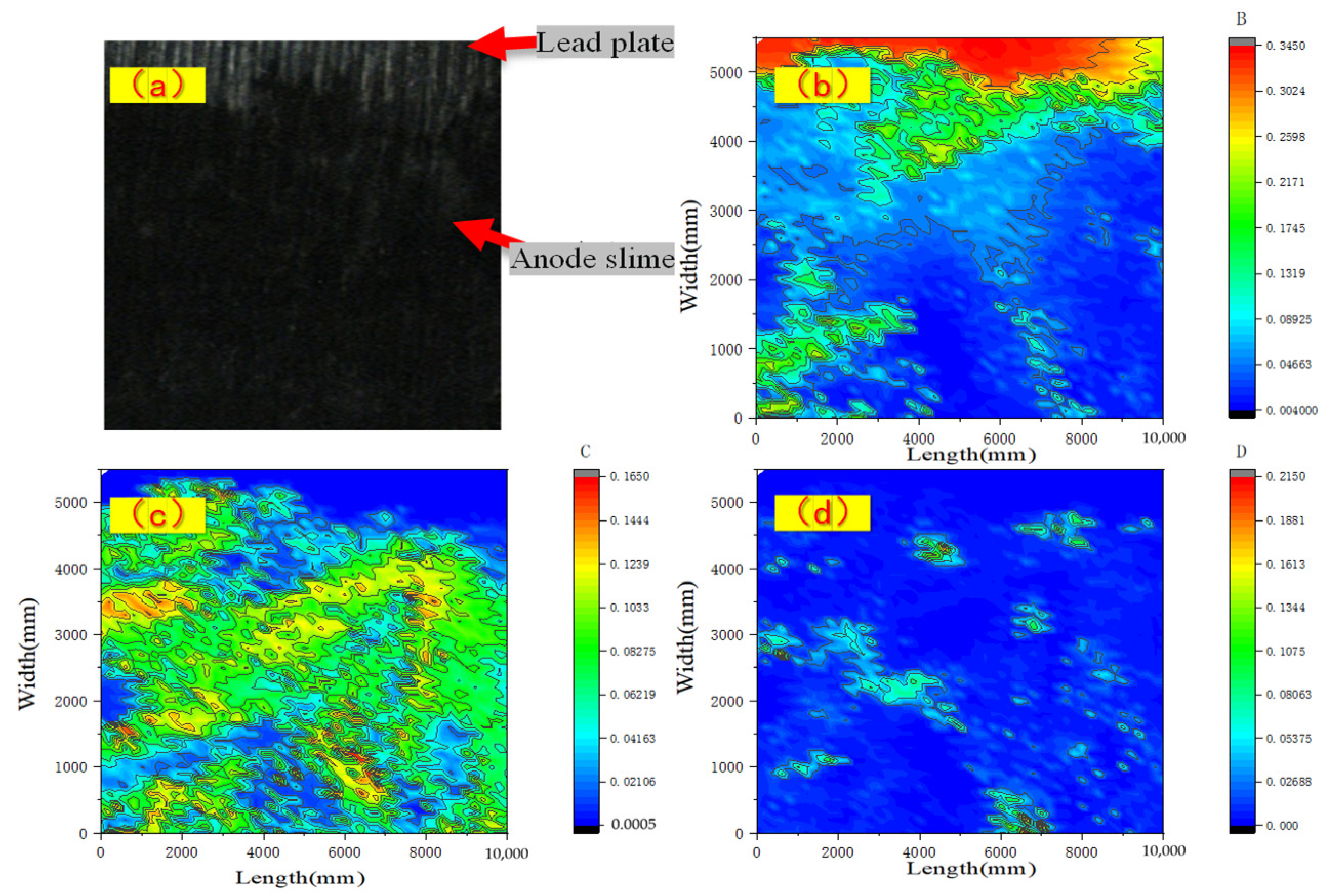
3.3.1. Spatial Distribution of Target Elements in Anode Slime on the Silting Plate and the Conventional Area

The cluster analysis required multiple groups of anode slime data from the silting area and the conventional area from energy dispersive X-ray fluorescence spectrometry (mm-XRF). The relationships between the contents of Pb, Mn and Zn elements of the slime-containing anode plate and the thickness of anode slime were reverted in a three-dimensional format.
As shown in Figure 11, Figure 11a shows the relationship between five groups of Pb content and anode slime thickness in the silting area, Figure 11b shows the relationship between five groups of Mn content and anode slime thickness in the silting area and Figure 11c shows the relationship between five groups of Zn content and anode slime thickness in the silting area. After removing a small amount of data outside 7 mm of the silting area and adding previous research data on conventional anode slime from the same enterprise, the data on Pb, Mn and Zn were fitted to obtain the relationship between the Pb, Mn and Zn contents in anode slime as well as the thickness of anode slime in the silting area and the conventional area, as shown in Figure 11d.
In Figure 11d, we found that the elemental Pb content and trends were similar between the silting area and the conventional area, within the range of 5 mm. The Pb content in the range of 2.5–5 mm was approx. 10%. In the conventional area, within the range of 5–6 mm, the Pb content was consistent with that in the range of 2.5–5 mm, while the Pb content in the silting area in the range of 5–7 mm showed an obvious upward trend, with a peak at 23%. The contents and trends of Mn in the silting area and the conventional area were similar within the range of 4 mm. However, in the range of 4–7 mm, in the silting area, Mn content decreased from 60% to 45%, and it was slightly higher in the conventional area than in the silting area. The contents and trends of Zn in the silting area were similar to those in the conventional area, within the range of 1.7 mm. Beyond the range of 1.7 mm, it was much higher in the silting area than in the conventional area, and the greatest difference in Zn content at the same thickness was approx. 20%. This may be due to the fact that the anode slime in the silting area had suffered more impact damage, thus more pores were formed and attached to more sulfate crystals of Zn.

3.3.2. Cluster Analysis of Elements in Anode Slime Resources on the Silting Plate and in the Conventional Area

The cluster heatmap has become a widely used statistical method in recent years; it can simply and efficiently aggregate a large number of data [24] and display the results intuitively in a gradual color band, so that the density and frequency of data can be visually presented. Anode slime with a thickness of 0.1 mm on the surface of a conventional anode plate (CAP) and a silted anode plate (SAP) can be regarded as a type of resource, and classified by using the complete-linkage algorithm according to the contents of Mn, Pb and Zn (Figure 12).
It can be seen from Figure 12 that anode slime in the silting area and the conventional area can be clustered into 11 categories, according to the corresponding relationship between their Mn, Pb and Zn contents and thickness, as shown in Figure 12a. Based on the demand of enterprises for anode slime recycling following the leaching process, the anode slime can be divided into three categories, with Mn content > 45% and Pb content < 20%, as shown in Figure 12b. High-Pb resources include 0–1.5 mm (CAP), 0–1.4 mm (SAP) and 6.3–7.0 mm (SAP), when Pb content > 20%. Low-Pb, high-Mn and high-Zn resources include 2.9–6.0 mm (SAP), when Pb content < 20%, Mn content > 45% and Zn content > 20%. Low-Pb, high-Mn and low-Zn resources include 1.6–6.0 mm (CAP), 1.5–2.8 mm (SAP) and 6.1–6.2 mm (SAP), with Pb content < 20%, Mn content > 45% and Zn content < 20%.
From the above, it can be seen that the anode slime in the silting area and the conventional area can be accurately categorized and scraped out according to the different relative element contents of Pb, Mn and Zn through real-time detection and cluster analysis of the anode slime thickness and element composition, and the high-Pb film layer can be retained to protect the anode surface. This research provides theoretical basis and key parameter support for realizing the anode slime resource utilization, for the goal of cleaner production in Zn hydrometallurgy.

4. Conclusions

(1)
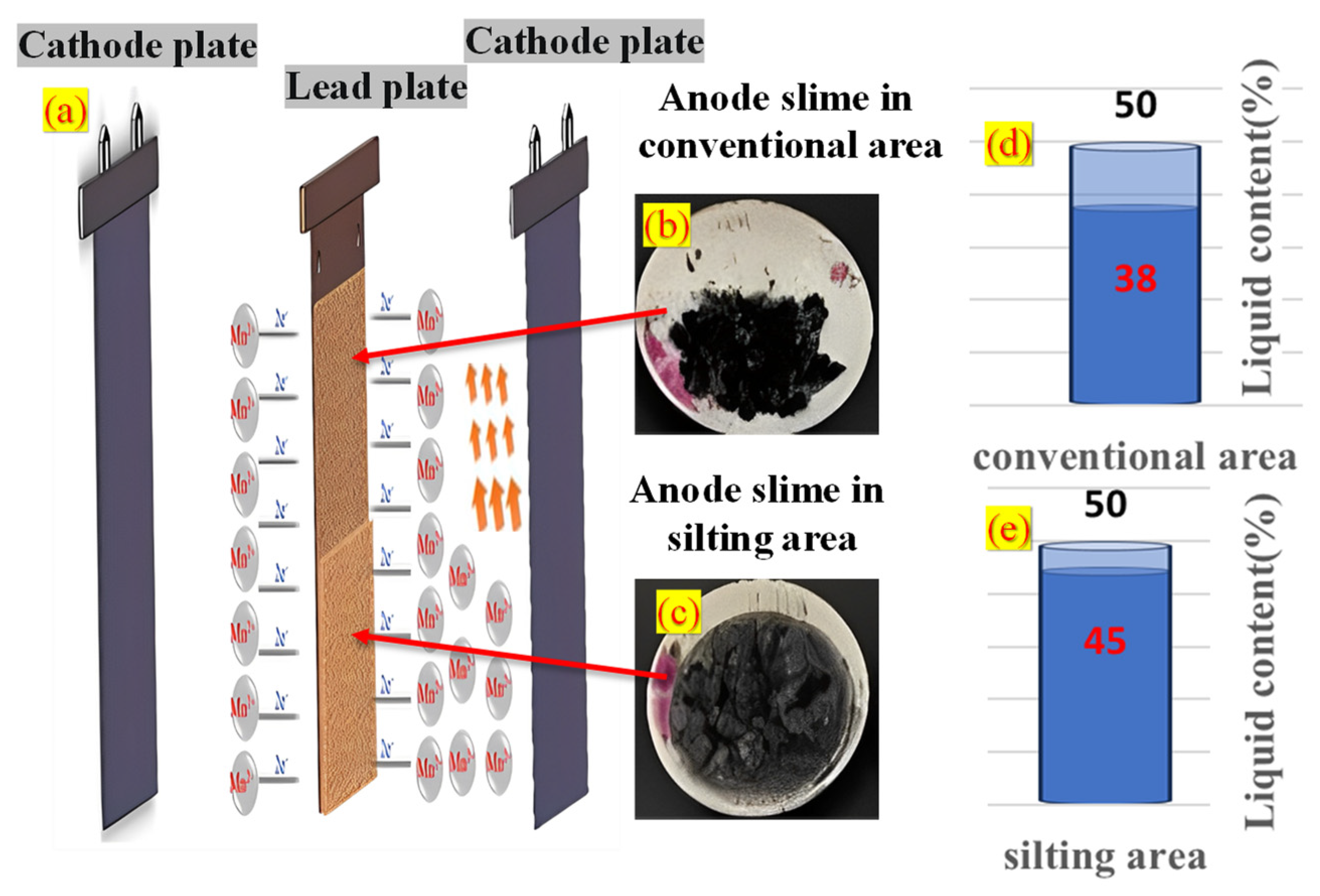
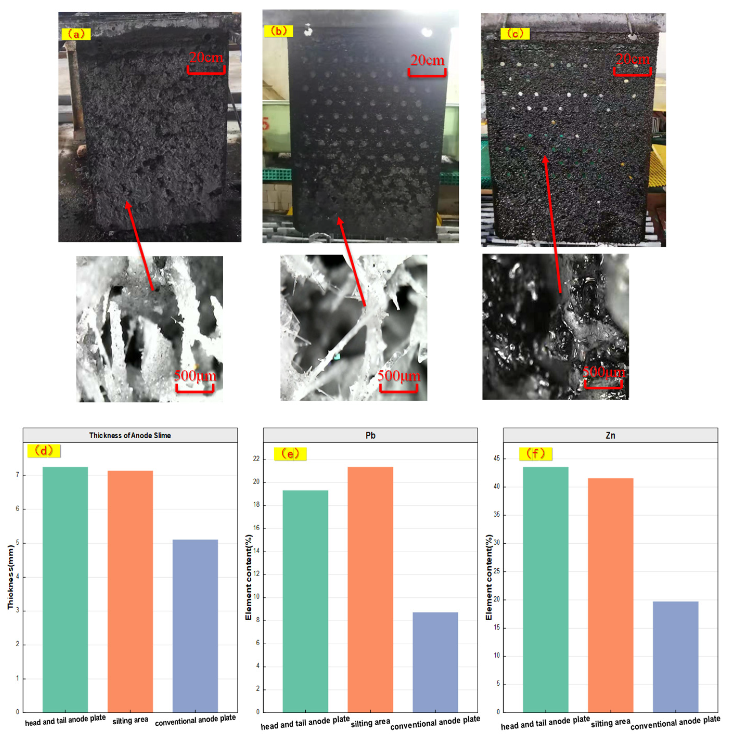
Based on mm-XRF, thickness measurement, morphology observation and liquid content detection, it is preliminarily determined that there were two different forms of electrolytic Zn anode slime, namely, silting area and conventional area, and the silting area accounted for about 15% of the total anode plates. Based on μ-XRF in-situ analysis of micro-area elements, it was found that there were lumps with fluorescence counting intensity that was close to pure Pb in anode slime in the silting area 3.9 mm away from the Pb-based surface.
(2)
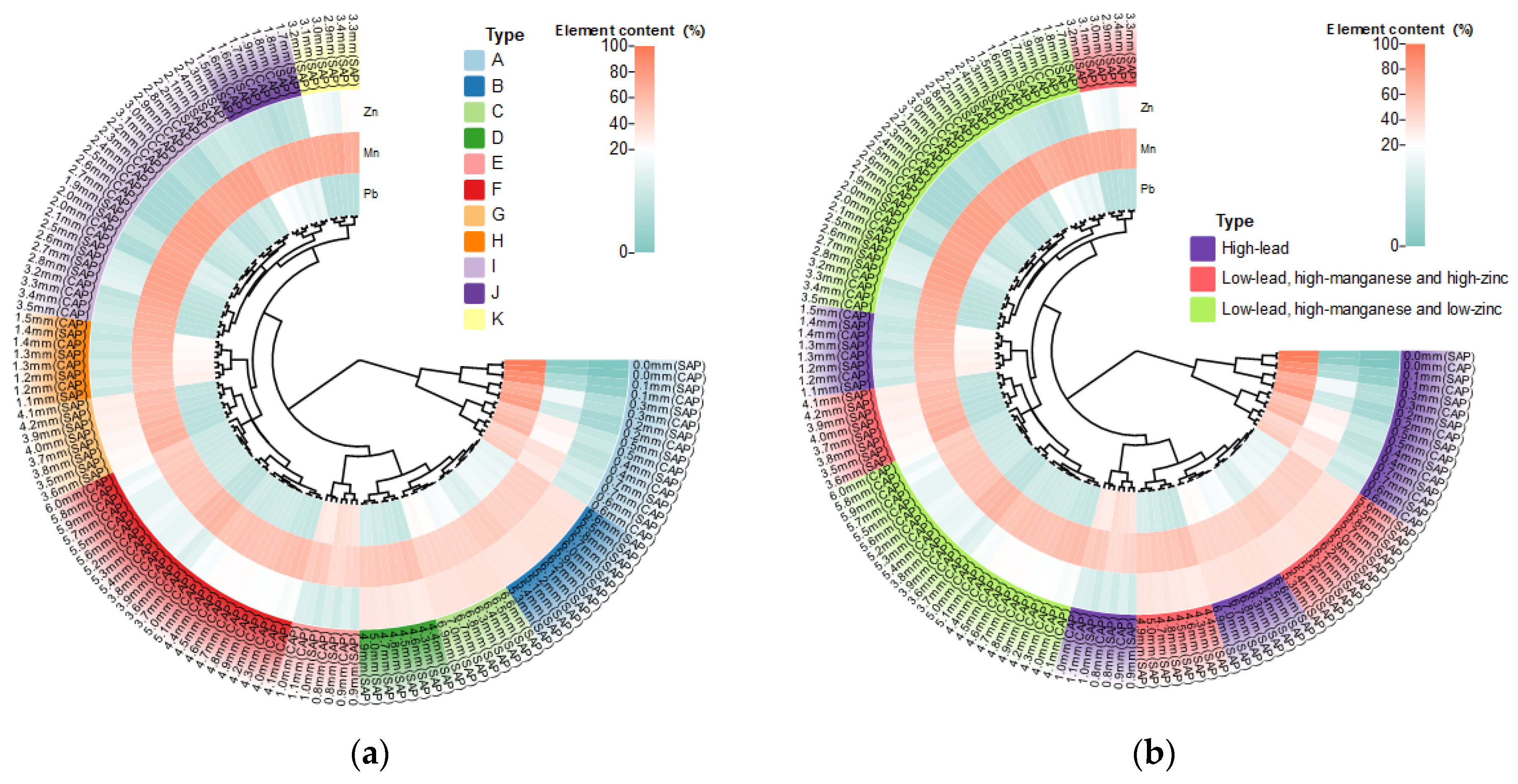
Through mm-XRF analysis of a large number of data on anode slime in the silting area and the conventional area, anode slime with a thickness of 0.1 mm in conventional and silting areas could be regarded as a kind of resource, and we categorized the resource with the use of a complete-linkage algorithm for clustering division (to supplement the conclusion on linear relationship between elements and thickness).
(3)
High-Pb resource at 6.3–7.0 mm (SAP); low-Pb, high-Mn and high-Zn resource at 2.9–6.0 mm (SAP) and low-Pb, high-Mn and low-Zn resources including 1.6–6.0 mm (CAP), 1.5–2.8 mm (SAP) and 6.1–6.2 mm (SAP) were scraped out and collected. High-Pb resources 0–1.5 mm (CAP) and 0–1.4 mm (SAP) were retained on the anode plate surface, to realize the Pb-sealed anode plate surface and to classify the resource recovery of anode slime. This provides a theoretical basis for the efficient resource utilization of anode slime in the Zn hydrometallurgy industry.

Author Contributions

Conceptualization, R.X.; Data curation, R.X.; Funding acquisition, L.J.; Investigation, R.X., G.Z., Y.L., C.Z., W.L. and Z.L.; Methodology, R.X. and L.J.; Project administration, L.J. and N.D.; Resources, L.J. and N.D.; Supervision, L.J. and N.D.; Validation, R.X.; Writing—original draft, R.X.; Writing—review & editing, L.J. and N.D. All authors have read and agreed to the published version of the manuscript.

Funding

This work is supported by the Fundamental Research Funds of the Central Government for Universities, Tongji University (No. 22120230146) and National Natural Science Foundation of China (52174385).

Data Availability Statement

The data presented in this study are available on request from the corresponding authors. The data are not publicly available because of continuous research.

Acknowledgments

This article is supported by Tongji University.

Conflicts of Interest

The authors declare no conflict of interest.

References

  1. Xu, F.Y.; Jiang, L.H.; Li, J.H.; Zou, C.; Wen, Y.C.; Zhang, G.; Li, Z.Q.; Duan, N. Mass balance and quantitative analysis of cleaner production potential in a Zn electrolysis cellhouse. J. Clean. Prod. 2016, 135, 712–720. [Google Scholar] [CrossRef]
  2. Karbasi, M.; Alamdari, E.K. Investigation of Pb base composite anodes produced by accumulative roll bonding. Mater. Des. 2015, 67, 118–129. [Google Scholar] [CrossRef]
  3. Zhang, C.; Jiang, L.; Xu, F.; Duan, N.; Xin, B.; Han, G.; Zhang, G.; Wen, Y. New insight into cleaner control of heavy metal anode slime from aqueous sulfate electrolytes containing Mn (II): Preliminary characterization and mechanism analysis. J. Clean. Prod. 2018, 177, 276–283. [Google Scholar] [CrossRef]
  4. Ye, W.; Xu, F.; Jiang, L.; Duan, N.; Li, J.; Ma, Z.; Zhang, F.; Chen, L. Pb release kinetics and film transformation of Pb-MnO2 pre-coated anode in long-term Zn electrowinning. J. Hazard. Mater. 2021, 408, 124931. [Google Scholar] [CrossRef]
  5. Ye, W.; Xu, F.; Jiang, L.; Duan, N.; Li, J.; Ma, Z.; Zhang, F.; Chen, L. A novel functional Pb-based anode for efficient Pb dissolution inhibition and slime generation reduction in Zn electrowinning. J. Clean. Prod. 2021, 284, 9776. [Google Scholar] [CrossRef]
  6. Jaishankar, M.; Tseten, T.; Anbalagan, N.; Mathew, B.; Beeregowda, B.; Krishnamurthy, N. Toxicity, mechanism and health effects of some heavy metals. Interdiscipl. Toxicol. 2014, 7, 60–72. [Google Scholar] [CrossRef] [PubMed]
  7. Ma, Z.; Jiang, J.; Duan, L.; Li, Z.; Deng, J.; Li, J.; Zhang, R.; Zhou, C.; Xu, F.; Jiang, L.; et al. Ultrasonication to reduce particulate matter generated from bursting bubbles: A case study on Zn electrolysis. J. Clean. Prod. 2021, 272, 122697. [Google Scholar] [CrossRef]
  8. Devoz, P.P.; Reis, M.B.D.; Gomes, W.R.; Maraslis, F.T.; Ribeiro, D.L.; Antunes, L.M.G.; Batista, B.L.; Grotto, D.; Reis, R.M.; Barbosa, F., Jr.; et al. Adaptive epigenetic response of glutathione (GSH)-related genes against Pb (Pb)-induced toxicity, in individuals chronically exposed to the metal. Chemosphere 2021, 269, 128758. [Google Scholar] [CrossRef]
  9. Liu, W.; Cui, Z.J.; Tian, J.P.; Chen, L.J. Dynamic analysis of Pb stocks and flows in China from 1990 to 2015. J. Clean. Prod. 2018, 205, 86–94. [Google Scholar] [CrossRef]
  10. Cao, J.L.; Zhao, H.Y.; Cao, F.H.; Zhang, J.Q. The influence of F−doping on the activity of PbO2 film electrodes in oxygen evolution reaction. Electrochim. Acta 2007, 52, 7870–7876. [Google Scholar] [CrossRef]
  11. Wang, S.; Zhou, X.; Ma, C.; Long, B.; Wang, H.; Tang, J.; Yang, J. Electrochemical properties of Pb-0.6 wt% Ag powder-pressed alloy in sulfuric acid electrolyte containing Cl/Mn2þ ions. Hydrometallurgy 2018, 177, 218–226. [Google Scholar] [CrossRef]
  12. Nijjer, S.; Thonstad, J.; Haarberg, G.M. Oxidation of Mn(II) and reduction of Mn dioxide in sulphuric acid. Electrochim. Acta 2000, 46, 395–399. [Google Scholar] [CrossRef]
  13. Mohammadi, M.; Alfantazi, A. Evaluation of Mn dioxide siltation on Pb-based electrowinning anodes. Hydrometallurgy 2016, 159, 28–39. [Google Scholar] [CrossRef]
  14. Tunnicliffe, M.; Mohammadi, F.; Alfantazi, A. Polarization behavior of Pb-silver anodes in Zn electrowinning electrolytes. J. Electrochem. Soc. 2012, 159, C170–C180. [Google Scholar] [CrossRef]
  15. Ivanov, I.; Stefanov, Y. Electroextraction of Zn from sulphate electrolytes containing antimony ions and hydroxyethylated-butyne-2-diol-1,4: Part 3. The influence of Mn ions and a divided cell. Hydrometallurgy 2015, 6, 181–186. [Google Scholar]
  16. Devilliers, D.; Thi, M.T.D.; Mahe, E.; Daruiac, V.; Lequeux, N. Electroanalytical investigations on electrodeposited Pb dioxide. J. Electroanal. Chem. 2004, 573, 227–239. [Google Scholar] [CrossRef]
  17. Tang, L.; Tang, C.; Xiao, J.; Zeng, P.; Tang, M. A cleaner process for valuable metals recovery from hydrometallurgical Zn residue. J. Clean. Prod. 2018, 201, 764–773. [Google Scholar] [CrossRef]
  18. Yang, H.T.; Liu, H.R.; Guo, Z.C.; Chen, B.M.; Zhang, Y.C.; Huang, H.; Li, X.L.; Fu, R.C.; Xu, R.D. Electrochemical behavior of rolled Pb-0.8% Ag anodes. Hydrometallurgy 2013, 140, 144–150. [Google Scholar] [CrossRef]
  19. Jaimes, R.; Miranda-Hernández, M.; Lartundo-Rojas, L.; González, I. Characterization of anodic deposits formed on Pb-Ag electrodes during electrolysis in mimic Zn electrowinning solutions with different concentrations of Mn(II). Hydrometallurgy 2015, 156, 53–62. [Google Scholar] [CrossRef]
  20. Xu, R.C.; Jiang, L.H.; Duan, N.; Xu, F.Y.; Zhang, F.L.; Zhou, C.; Li, W.D.; Li, Z.Q. Research on microstructure of membrane-slime layer on lead-based anode surface in zinc hydrometallurgy by combining μ-XRF with mm-XRF. J. Clean. Prod. 2022, 379, 1. [Google Scholar] [CrossRef]
  21. Terzano, R.; Al Chami, Z.; Vekemans, B.; Janssens, K.; Miano, T.; Ruggiero, P. Zn distribution and speciation within rocket plants (Eruca vesicaria L. Cavalieri) grown on a polluted soil amended with compost as determined by XRF microtomography and micro-XANES. J. Agric. Food Chem. 2008, 56, 3222–3231. [Google Scholar] [CrossRef]
  22. Peng, C.; Xu, C.; Liu, Q.; Sun, L.; Luo, Y.; Shi, J. Fate and Transformation of CuO Nanoparticles in the Soil–Rice System during the Life Cycle of Rice Plants. Environ. Sci. Technol. 2017, 51, 4907–4917. [Google Scholar] [CrossRef] [PubMed]
  23. Xing, L.D.; O’Connor, J.K.; McKellar, R.C.; Chiappe, L.M.; Bai, M.; Tseng, K.W.; Zhang, J.; Yang, H.D.; Fang, J.; Li, G. A flattened enantiornithine in mid-Cretaceous Burmese amber: Morphology and preservation. Sci. Bull. 2018, 63, 235–243. [Google Scholar] [CrossRef] [PubMed]
  24. Rajabi, A.; Eskandari, M.; Ghadi, M.J.; Li, L.; Zhang, J.F.; Siano, P.A. Comparative study of clustering techniques for electrical load pattern segmentation. Renew. Sust. Energ. Rev. 2020, 120, 109628. [Google Scholar] [CrossRef]
Figure 1. (a) Schematic Diagram of Zn–Electrowinning Electrolysis cell Arrangement and Sampling Positions in the Enterprise. (b) Schematic Diagram of mm-XRF Sampling Positions.
Processes 11 02585 g001
Figure 2. Integral Slime Anode Plate Sealed by Epoxy Resin. The sampling regions of the experimental samples from the silting area for mm-XRF analysis are labeled as 1# to 5#.
Processes 11 02585 g002
Figure 3. Epoxy Resin-Sealed Slime-Containing Anode Plate Samples.
Processes 11 02585 g003
Figure 4. Thickness of Anode Slime on the Anode Plate after Zn Electrowinning for 1–12 Days.
Processes 11 02585 g004
Figure 5. Pb Content in Anode Slime on Anode Plate after 1–12 Days of Zn Electrowinning.
Processes 11 02585 g005
Figure 6. Mn Content in Anode Slime on Anode Plate Surface after 1–12 Days of Zn Electrowinning.
Processes 11 02585 g006
Figure 7. Zn Content in Anode Slime on Anode Plate after 1–12 Days of Zn Electrowinning.
Processes 11 02585 g007
Figure 8. (a) Pictures of the Head and Tail Silted Plate with Local Microscopy at 160 Times Magnification. (b) Pictures of the Partially Silted Plates with Silting Area Microscopy at 160 Times Magnification. (c) Pictures of the Conventional Area with Local Microscopy at 160 Times Magnification. (d) Anode Slime Thickness of the Head and Tail Silting Plate and the Silting Area and Conventional Area. (e) Surface Pb Content of Anode Slime on the Head and Tail Silting Plate and the Silting Area and Conventional Area. and (f) Surface Zn Content of Anode Slime on the Head and Tail Silting Plate and the Silting Area and Conventional Area.
Processes 11 02585 g008
Figure 9. (a) Schematic Diagram of Possibility of Silting Area Formation. (b,c) Anode Slime Powder Samples Taken from the Silting Area and the Conventional Area. (d,e) liquid content of Anode Slime in the Silting Area and the Conventional Area.
Processes 11 02585 g009
Figure 10. (a) Sample Picture of Anode Slime Silting Area of Pb-Containing Plate Sealed by Epoxy Resin. (bd) are the Mapping of Pb, Mn and Zn Contents and Fluorescence Counting Intensity Table of the Sample Synchrotron Radiation respectively. The red area has high value and relatively high element contents, while the blue area has low value and relatively low element contents.
Processes 11 02585 g010
Figure 11. (ac) show the relationship between the Pb, Mn and Zn contents and the thickness of anode slime in the silting area. (d) shows the relationship between the fitted Pb, Mn and Zn contents and the thickness of anode slime in the silting area and the conventional area.
Processes 11 02585 g011
Figure 12. (a) Cluster Heatmap Analysis of Main Element Contents in Anode Slime. (b) Cluster Heatmap Analysis of Main Element Content of Anode Slime Based on Enterprise Demand.
Processes 11 02585 g012
Disclaimer/Publisher’s Note: The statements, opinions and data contained in all publications are solely those of the individual author(s) and contributor(s) and not of MDPI and/or the editor(s). MDPI and/or the editor(s) disclaim responsibility for any injury to people or property resulting from any ideas, methods, instructions or products referred to in the content.

