Article

Design and Study of a Large-Scale Microwave Plasma Torch with Four Ports

1
College of Electronic and Information Engineering, Sichuan University, Chengdu 610065, China
2
School of Electronic and Communication Engineering, Guiyang University, Guiyang 550005, China
*
Author to whom correspondence should be addressed.
Processes 2023, 11(9), 2589; https://doi.org/10.3390/pr11092589
Submission received: 29 July 2023 / Revised: 15 August 2023 / Accepted: 24 August 2023 / Published: 29 August 2023

Abstract

:
The microwave plasma torch (MPT) has gained popularity in industrial applications due to its high energy density, ionization levels, and high temperature. However, the non-uniform and unstable plasma generated by microwave plasma sources has limited the production of large-scale MPTs. This paper proposes a novel MPT device utilizing a four-port microwave source (2.45 GHz, 4 kW) to address these issues. The improved plasma uniformity and stability are achieved through the new structure, and the microwave efficiency is enhanced by introducing the focusing dielectric in the coupled cavity. Using a 3D electromagnetic field model, microwave plasma model and fluid model, the paper optimizes the geometry and inlet mode of the MPT device. Experimental results show that the novel MPT device can generate a plasma torch with a maximum height of 545 mm, a working range of 10–95 L/min, and a microwave efficiency up to 86%. The proposed device not only competently meets industrial requirements, but also provides design ideas and methods for future MPT devices.

1. Introduction

With its advantages of a wide range of working pressure [1,2], high energy conversion rate [3,4,5,6], no electrode pollution [7], high electron density and electron temperature [8], the microwave plasma torch (MPT) has become an attractive plasma source in both scientific research studies and industrial applications [9]. Especially in solid waste treatment, the MPT incineration inhibits NOx SOx generation [10,11,12,13], which is an environmentally friendly treatment [14]. However, most of the current MPT devices have two main problems, small size of the plasma torch and narrow working range [4,15,16,17], which are difficult to meet the requirements of industrialization.
There are two main types of microwave plasma torches (MPTs) used to generate large plasma torch sizes: those based on tapered waveguides and those based on ridged waveguides. The diameter of the plasma generated by these MPTs has reached 30 mm [18]. By optimizing the MPT structures, the size of the plasma torch and microwave efficiency can be increased. Xiao et al. designed an MPT based on a ridged waveguide with an oblique hole, which increased power transfer efficiency from microwave to plasma by 11%. At a microwave power of 1.5 kW, the height of the plasma torch reached 210 mm, and the gas inflow rate ranged from 8.3 to 16.7 L/min [5]. Chen et al. designed an MPT based on a multi-ridge field compressed reactor, which could sustain a long-length plasma, achieved a best transfer efficiency of 95.2%, and a working inflow rate ranging from 6 to 10 L/min [19]. Additionally, D’Isa et al. studied an MPT with swirling gas flow, which achieved a gas inflow rate up to 30 L/min at a microwave power of 6 kW [20]. However, these structures compress the space in the plasma excitation region, and the plasma torches cannot be maintained when increasing the inflow rate. Moreover, the MPT devices, limited by the waveguide structure, make it difficult to increase the diameter of the plasma torch further.
In studies focused on widening the working range of MPTs, researchers have found that enhancing the electric field in the plasma generation region can increase the plasma generation rate and improve the stability of plasma torches. Nowakowska et al. designed a novel microwave plasma source with a unique sheet-shaped plasma that achieved a maximum argon inflow rate of up to 30 L/min [21]. Ouyang et al. developed an atmospheric-pressure helium-MPT device with a gas inflow rate ranging from 20 to 50 L/min [22]. Leins et al. modified the original design of the University of Stuttgart’s microwave plasma torches [23] to generate a plasma torch with a diameter of 8 mm and a height of 100 mm, with a gas inflow rate ranging from 1 to 100 L/min [24]. Hrycak et al. proposed a cylindrical type, no-nozzle microwave plasma source with a gas inflow rate ranging from 25 to 65 L/min [25]. These methods increased the stability of the plasma torch by generating a region with very high electric field intensity, causing the working gas to be rapidly excited. However, compressing the plasma in a small region reduced the size of the plasma torch and decreased the microwave efficiency.
In this paper, a new structure for microwave plasma generators and gas inlet units to overcome deficiencies associated with MPTs in terms of plasma uniformity and stability was proposed. The coupling cavity in the generator creates a quasi-coaxial structure with the plasma, increasing the uniformity of the plasma and the diameter of the plasma torch. Additionally, the focusing dielectric (a dielectric with a ring structure, which can focus the electric field on the target region [26]) increases the microwave efficiency. The gas inlet unit features a porous horizontal inlet that improves the stability of the plasma excitation region.

2. Geometric and Model

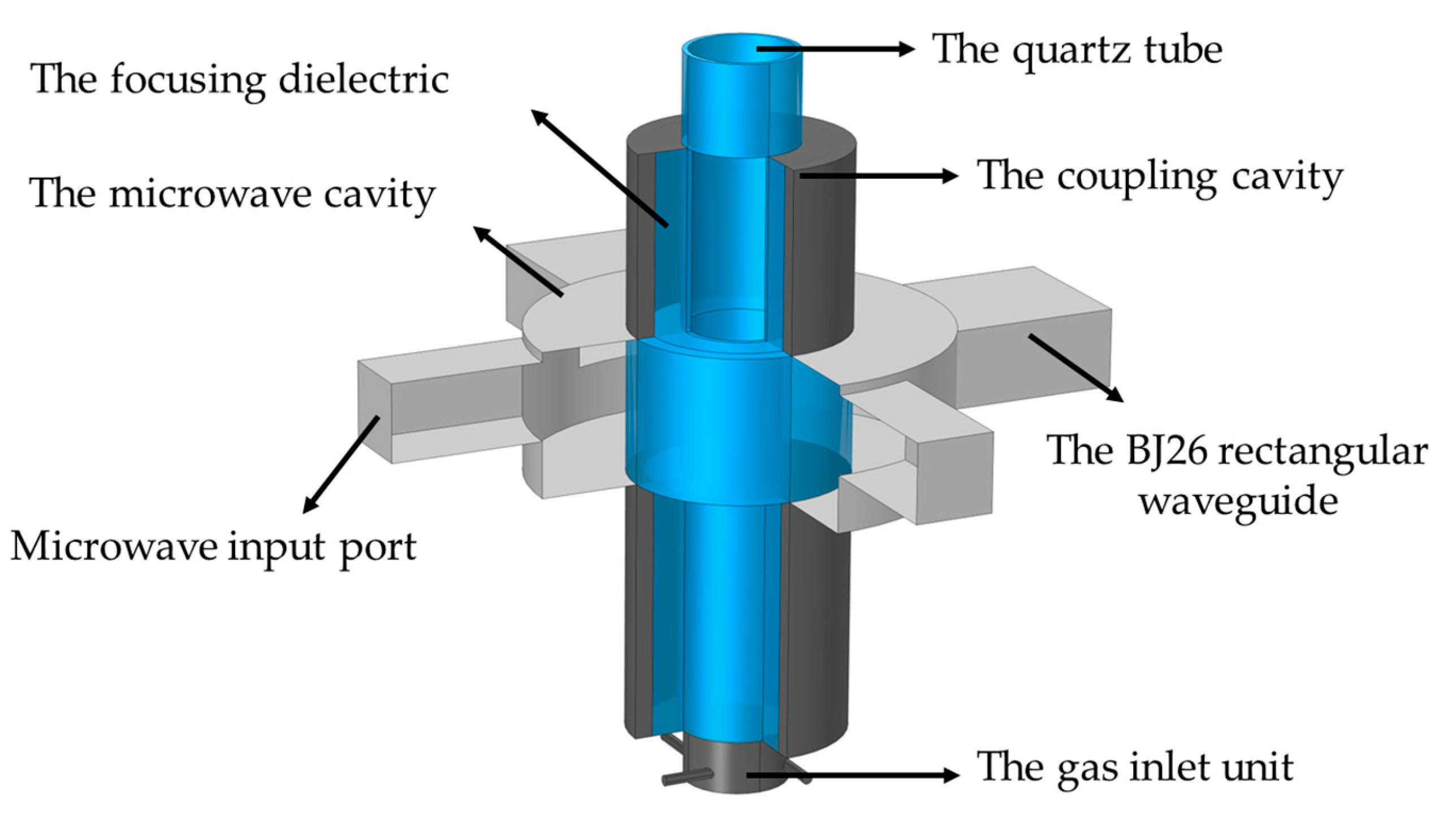
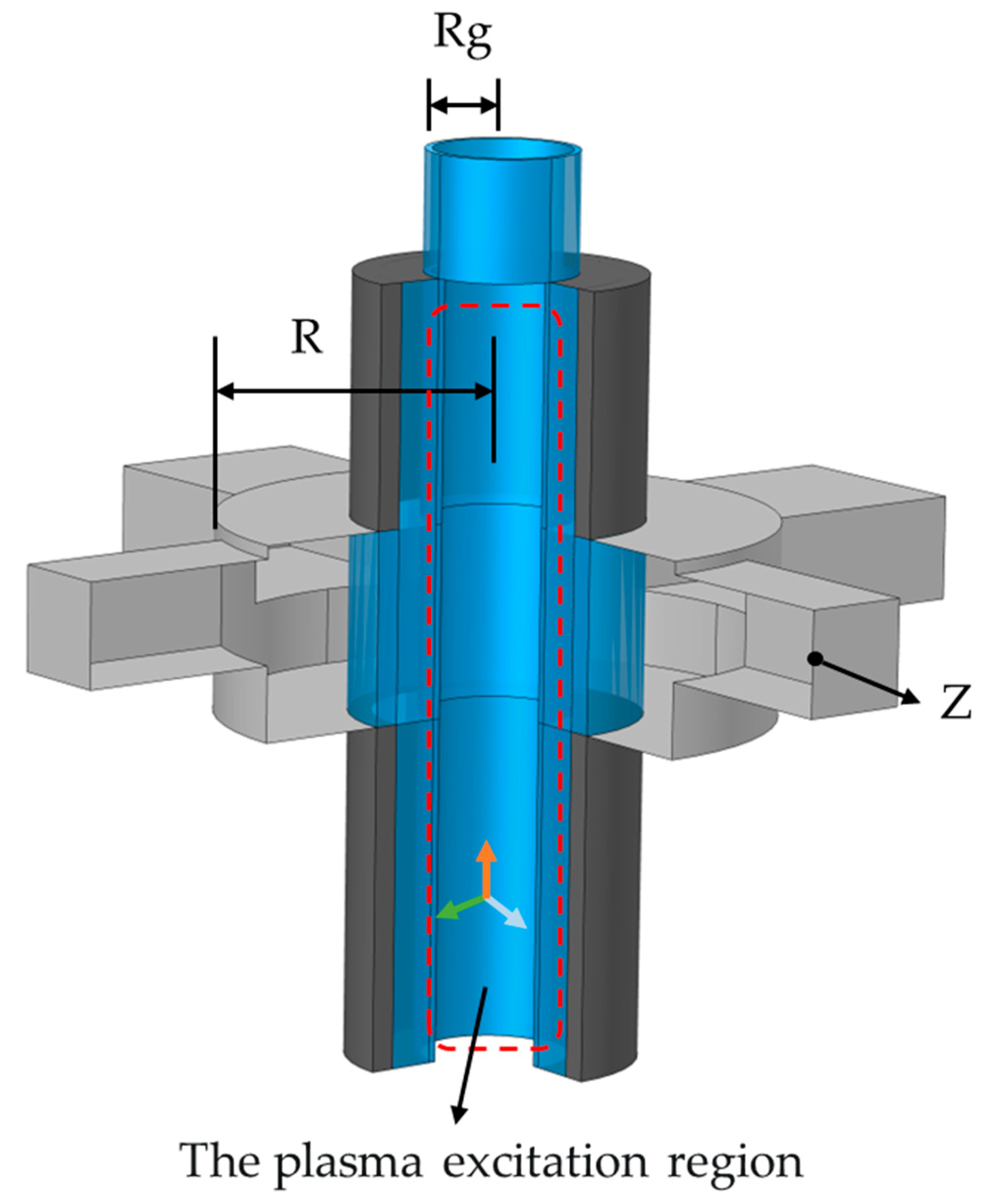
2.1. Geometric of MPT Device

As shown in Figure 1, the MPT device consists of the plasma generator and the gas inlet unit. The plasma generator consists of the microwave cavity, the coupling cavity (electric field coupling forms a coaxial structure to improve energy utilization rate [9]), four BJ26 rectangular waveguides and the quartz tube. The focusing dielectric is made of quartz material, which is filled between the coupling cavity and the quartz tube. The four waveguides are located in the same horizontal plane, with azimuth differences of 90°. The microwave cavity, the coupling cavity, the quartz tube and the gas inlet unit are coaxial. The bottom of the quartz tube is connected to the gas inlet unit.

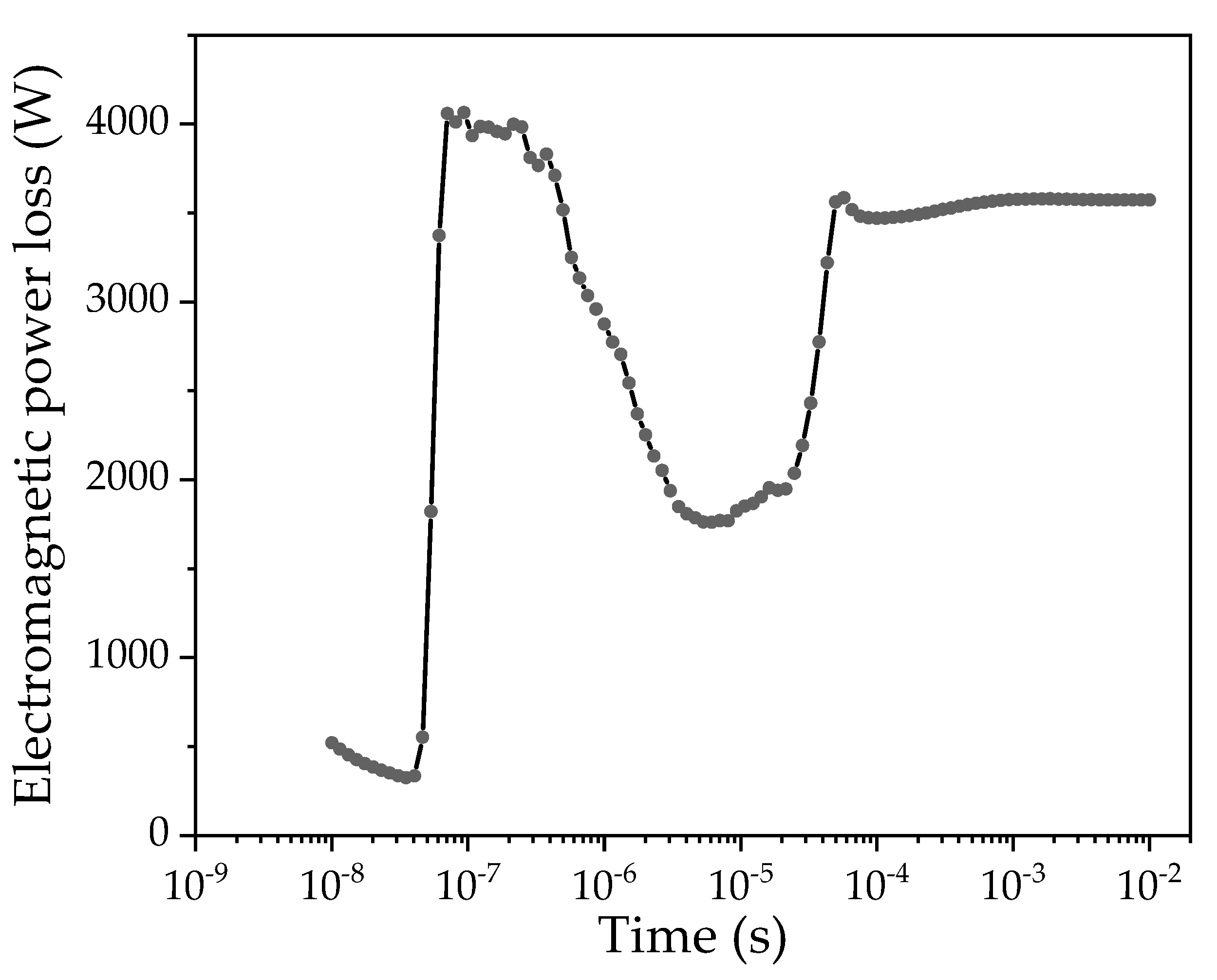
2.2. Electromagnetic Field Model

The microwave plasma is sustained by the electric field, which accelerates the seed electrons to interact with the working gas molecules. Therefore, the microwave plasma state depends on the electric field [27,28]. The microwave electric field in the MPT generator can be modeled by solving the following Maxwell’s equation:
× ( μ r 1 × E ) k 0 2 ( ε r j σ ω ε 0 ) E = 0 ,
where E is the microwave electric field, k0 = 2π/λ0 is the wave number of the microwave in free space, λ0 is the wavelength of the microwave, ε0 is the permittivity, σ is the plasma conductivity, and εr and μr are the relative permittivity and relative permeability. The relative permittivity εr and the plasma conductivity σ should be determined for two kinds of regions:
a. In the region where no plasma exists:
ε r = 1   and   σ = 0 ,
b. In the region where a plasma exists [29]:
ε r = ε p = 1 ,
σ = σ p = n e e 2 / m e ( v m j ω ) ,
where ω is the microwave angular frequency, e is the electron charge, me is the electron mass, and νm = νe = Re/ne is the electron collision frequency for momentum transfer. When the electron density reaches the critical electron density (ne = 7.6 × 10¹⁶ 1/m3), it is difficult for microwaves to propagate in the plasma, and the plasma can be regarded as an electrical conductor [30].

2.3. Plasma Model

The microwave plasma model describes the plasma kinetics, the energy conservation of electrons and heavy particles under the microwave action [31,32,33].
n e t + Γ e + ( u ) n e = R e ,   with   Γ e = ( μ e E ) n e D e n e ,
n ε t + Γ ε + E Γ e + ( u ) n ε = S e n ,   with   Γ ε = ( μ ε E ) n ε D e n n ε ,
E = V ,
( ε 0 ε r E ) = ρ q ,
Equation (5) describes the rate of change of the electron density, where μe = e/meνe is the electron mobility, De = kbTe/meνe is the electron diffusion coefficient. Equation (6) describes the rate of change of the energy density of the electrons, where nε is the mean electron energy, kb is the Boltzmann constant. Then, De = μeTe, με = 5μe/3, Dε = 5μeTe/3. The source term in Equations (5) and (6), Re, describes the production–destruction of electrons, Sen describes the anergy gain or loss elastic and inelastic collisions of electrons with the heavy species in the mixture, as
R e = n e j = 1 M x j N j K j ,
S e n = n e j = 1 P x j N j K j Δ ε j ,
where M is the number of loss/gain electrons for reaction, P is the number of elastic/inelastic collisions of electrons, xj is the mole fraction of the target substance for j, Nj is the number density of target species for reaction j, Kj is the rate coefficient for reaction j, and Δεj is the energy loss/gain from reaction j. The plasma reactions considered in this work shown as Table 1.
Equations (7) and (8) describe the space electrostatic field, ρq, which is the space charge density from the plasma chemistry. The equations of state of ideal gas and Dalton’s law are further used.

2.4. Fluid Model

The fluid field model describes the mass continuity and momentum conservation by the Navier–Stokes equations for laminar flow,
ρ u t + ρ ( u ) u = [ p I ^ + κ ^ ] + F ,   with   ρ u = 0 ,
where ρ is the total gas pressure, κ ^ is the viscous stress tensor for a Newtonian fluid, and I ^ is the identity matrix.

3. Simulation and Optimization

In this paper, the multi-physics simulation software COMSOL 4.3b, based on the finite element method, is utilized to simulate the MPT device. The simulation of the electric field in the plasma generator (as shown in Figure 2) is performed based on the electromagnetic field model. The coordinate axis center is defined as the center of the microwave cavity, with the microwave cavity radius denoted as R, the radius of the quartz tube as Rg, and the vertical coordinate of the center of the rectangular waveguides as Z. The plasma excitation region is located within the interior of the quartz tube. By performing a parameterized scan of the aforementioned variables, the optimal size parameters of the generator are determined.
According to fluid theory, four kinds of gas inlet units (shown as Figure 3) were designed, which could produce spiral fluid (the spiral flow helps stabilize the discharge [36]) in this paper. Based on the fluid field model, the flow field in the quartz tube was simulated.

3.1. The Plasma Generator Optimization

We setting the microwave frequency to 2.45 GHz and the microwave power to 1 kW per port. In order to simplify the calculation, the plasma is set to be evenly distributed in the plasma excitation region to calculate the microwave energy utilization rate [37]. The microwave energy utilization rate (efficiency) as
η = P l / P i × 100 %
where Pl is the electromagnetic power loss and Pi is the input microwave power.
The microwave efficiency corresponding to the radius of the quartz tube (Rg) and the radius of the microwave cavity (R) is shown in Figure 4. When Rg is between 27 mm and 27.5 mm, and R is between 103.5 mm and 112.5 mm, the microwave efficiency is approximately 80%. Moreover, when Rg is between 31 mm and 32.5 mm, and R is between 103 mm and 116 mm, the microwave efficiency exceeds 87.5%. Notably, within this range, the microwave efficiency remains stable, and the fault tolerance is high, which helps to mitigate the influence of plasma torch due to machining errors and device deformation at high temperatures. Consequently, for this study, the geometric dimensions of Rg = 31.5 mm and R = 110 mm were selected for the quartz tube and microwave cavity, respectively.
Based on the above results, the position of the microwave input ports is further optimized. Defining the position of the ports when located in the center of the microwave cavity, Z = 0 mm. The results in Figure 5 show that, as the ports are positioned away from the center of the microwave cavity (Z = 0 mm), the microwave efficiency increases. When Z = −14 mm and Z = 13 mm, the microwave efficiency is close to 90%. In this paper, Z = 13 mm was selected as the position of the ports.

3.2. Plasma Torch Simulation and Analysis

In this study, a steady-state fluid field in the quartz tube was calculated at an inflow rate of 10 L/min to evaluate the performance of four gas inlet units (as shown in Figure 3) designed to produce a spiral flow to stabilize the discharge. The simulation results show that the spiral flow can be generated by those inlet units. For the horizontal inlet mode, the fluid formed by it mainly flows in the radial direction (shown as Figure 6a,c). However, for the oblique inlet mode, the velocity of the fluid axis formed by it increases significantly (shown as Figure 6b,d).
In the case of the same inflow rate, the faster the axial flow rate, the faster the plasma flows out of the generator, and the lower the plasma electron density in the generator, resulting in lower stability [38]. The gas flow generated by the four-hole horizontal inlet unit mainly flows in the radial direction, and the flow rate in the axial direction is low (shown as Figure 6c), so the generated plasma can be more stable. The influence of different inlet units on plasma morphology will be analyzed by experiments in the following sections.
The geometric structure of the plasma generator was determined through simulation and optimization. After analyzing the gas inlet units, the four-port horizontal gas inlet unit was selected. The fluid model and microwave plasma model were combined to simulate the microwave plasma torch. Figure 7 shows the calculation results for an inflow rate of 10 L/min. When t > 0.001 s, the electromagnetic loss stabilizes. Therefore, the plasma torch is considered to have reached a steady state after t > 0.001 s, and the microwave efficiency value at t = 0.01 s is taken as the simulation result.
The electron density distribution and the electric field distribution after the plasma torch is stabilized, as shown in Figure 8. The results show that the device can produce a large size of plasma in the plasma excitation region, with the electron density of the plasma in the central region exceeding 2 × 10²⁰ 1/m3. The coupling cavity and plasma form a quasi-coaxial structure, shown as Figure 8b, so that the surface wave with high electric field intensity is formed on the plasma surface to enhance the stability of the plasma and increase the size of the plasma.

4. Experimental Results and Discussion

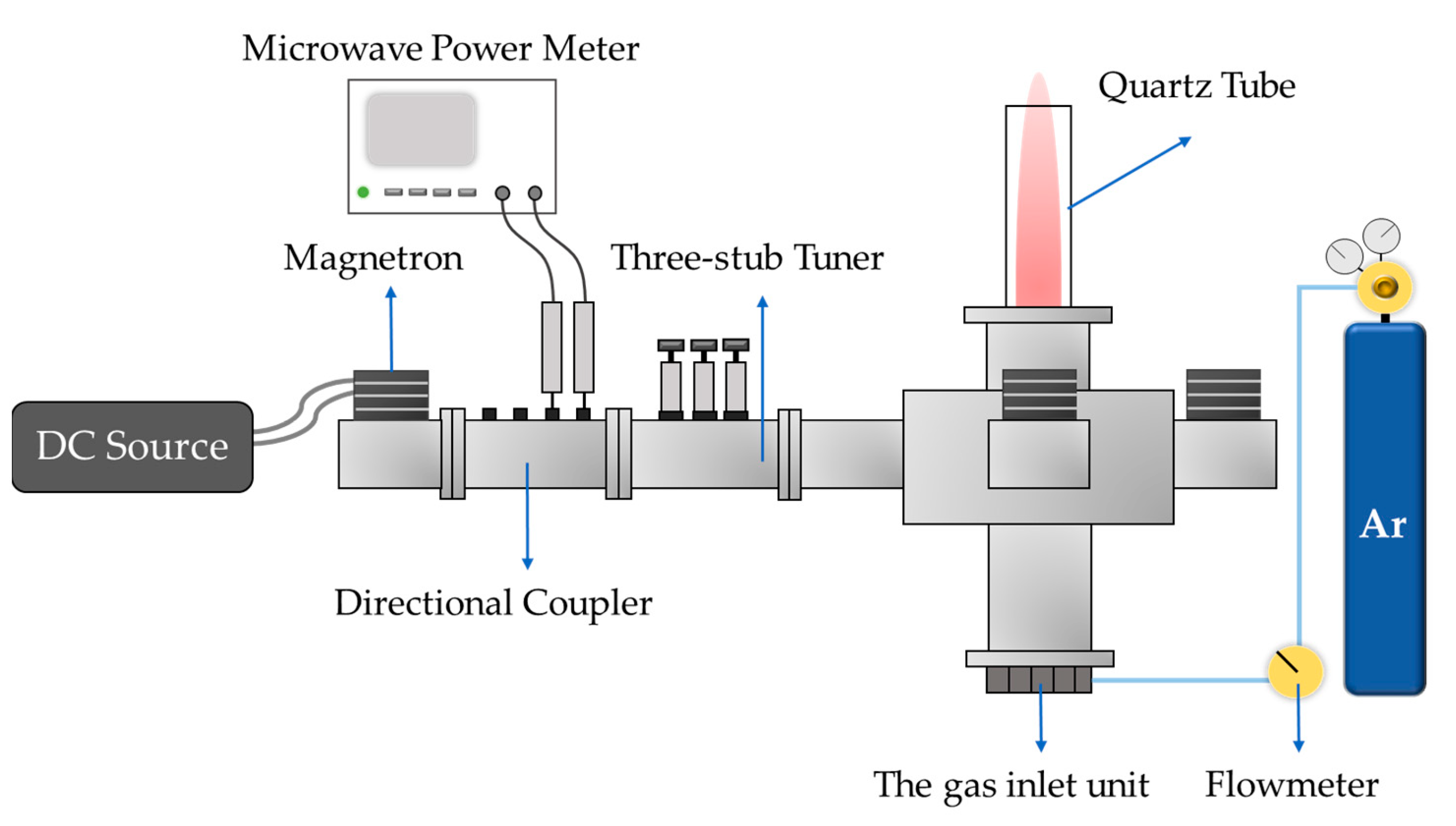
4.1. Experimental System

An MPT experimental system was set up, as shown in Figure 9. The system uses a WEPEX 1280A DC source (MEGMEET, Shenzhen, China) to supply power to a Panasonic 2M244-M1 magnetron. The maximum output power of the magnetron is 1 kW, the magnetron is connected with the double-directional coupler and the rectangular waveguide port of the plasma generator. In the experiment, argon gas with a concentration of 99.99% was used, and the gas entered the reaction chamber from the gas inlet unit at the bottom of the plasma generator. During the experiment, the incident power and reflected power of each port were measured with a Keysight N1912A microwave power meter (KEYSIGHT, Santa Rosa, CA, USA), and the inlet gas flow was measured with a flowmeter. The experimental system is shown in Figure 10.

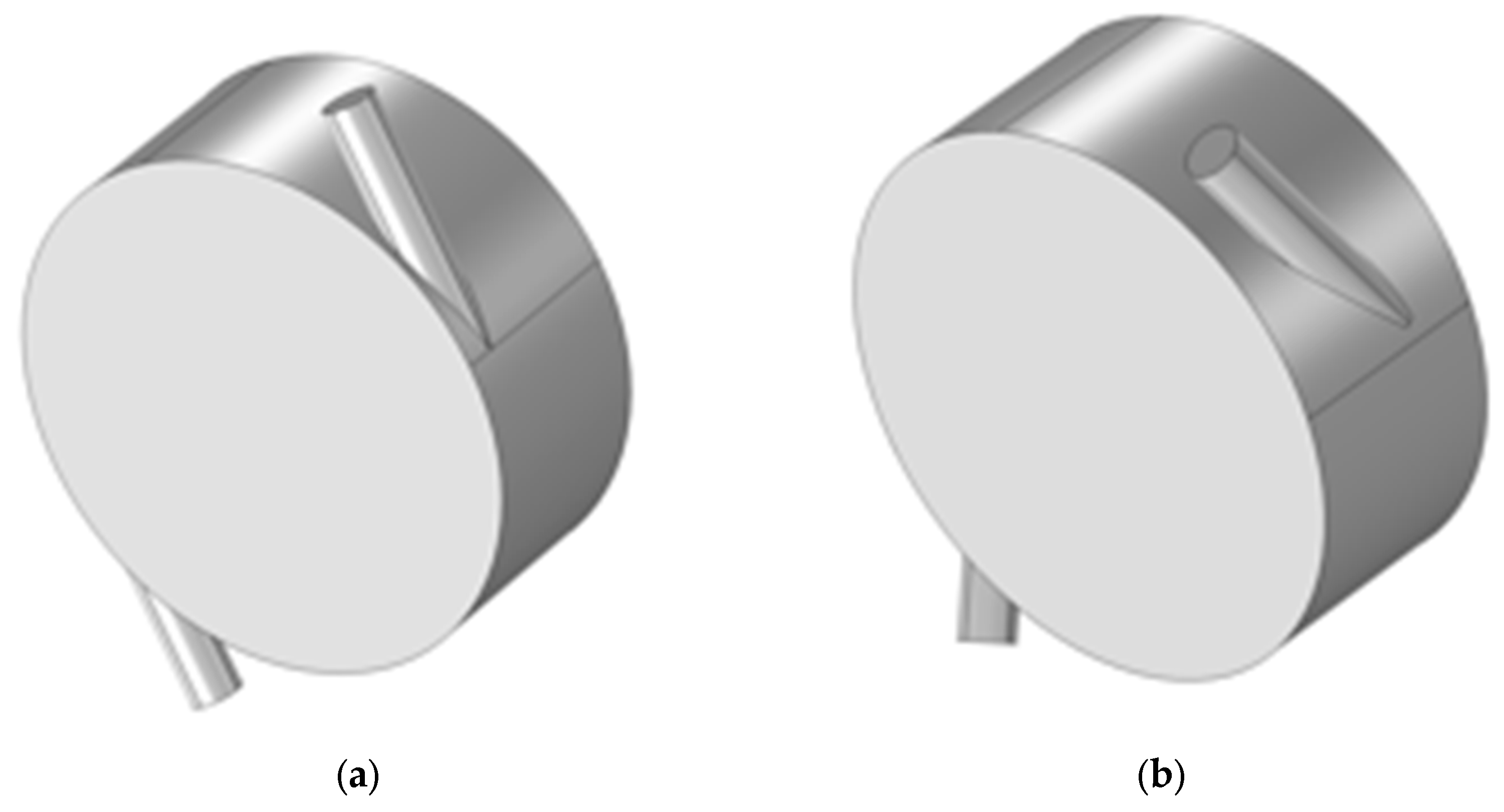
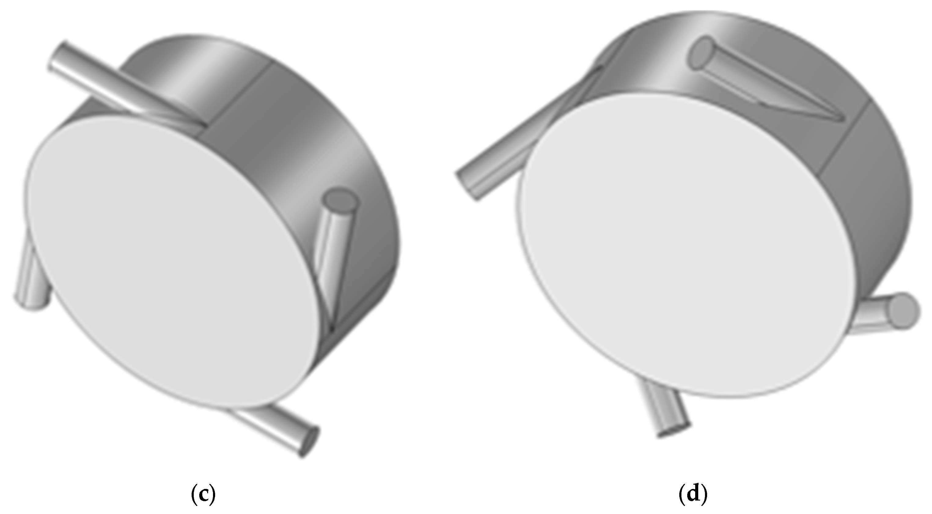
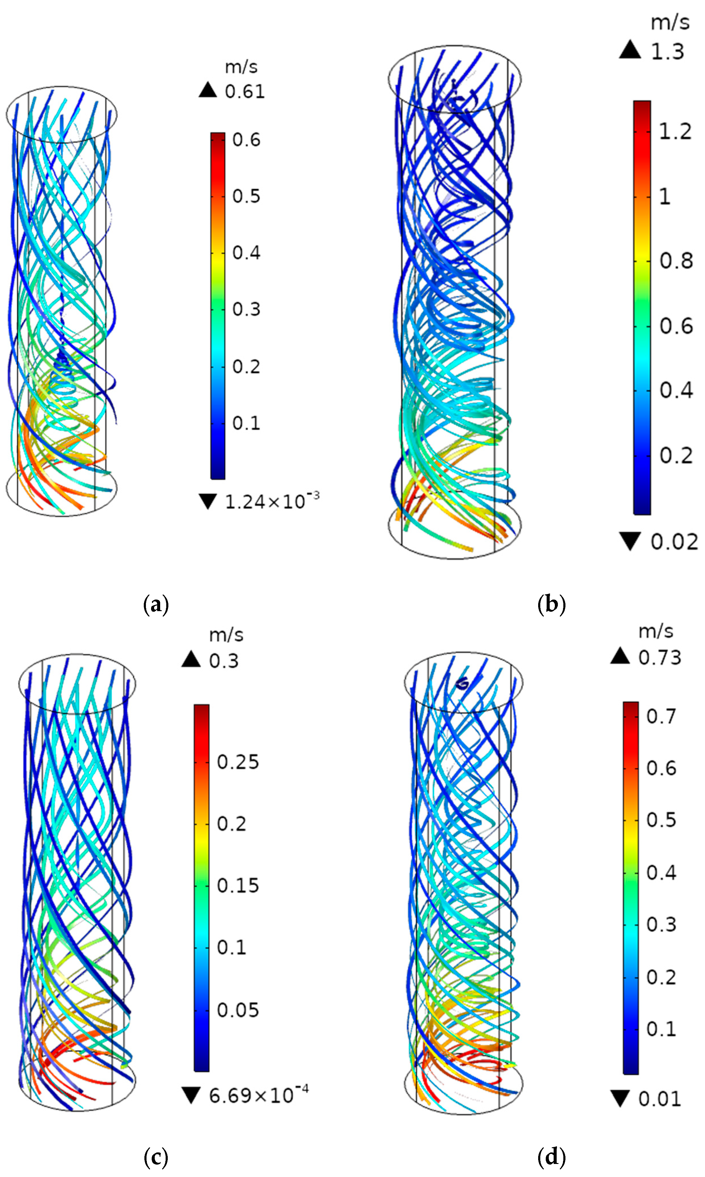
4.2. Influence of Gas Inlet Modes on the Plasma Torch

The height of plasma torches generated by the four inlet units is shown in Figure 11. It reaches its highest point at an inflow rate of 20 L/min, and decreases as the inflow rate increases. When the two-hole and four-hole inclined inlet units are used, the height of the plasma torch first increases and then decreases with increasing inflow rate, followed by a sharp drop. For an inflow rate of 20 L/min, the height of the plasma torch is 470 mm and 520 mm, as shown in Figure 12b,d, respectively, and the threshold inflow rate (at which the plasma torch height is 0 mm) is 70 L/min and 82 L/min, respectively. On the other hand, when two-hole and four-hole horizontal inlet units are employed, the height of the plasma torch also follows a similar pattern of initially increasing and then decreasing with increasing inflow rate, but the change trend is relatively flat. The height of the plasma torch is approximately 490 mm and 545 mm for an inflow rate of 20 L/min, as shown in Figure 12a,c, respectively, and the threshold inflow rate is 89 L/min and 95 L/min, respectively.
Combined with the simulation and experiment results, the analysis reveals the following:
a. Increasing the number of inlet holes results in a more even division of gas flow into multiple gas inlet routes, particularly under low inflow rates. This has a positive impact on the uniformity of gas flow in the plasma excitation region, leading to a more uniform plasma with higher electron density. Consequently, the height of the plasma torch is increased;
b. An increase in the angle of the inlet leads to an increase in the axial velocity in the plasma excitation region. However, at high inflow rates, the plasma accelerates away from the excitation region, resulting in a decrease in electron density and stability of the plasma torch, and consequently narrowing the working range.
Experiments confirmed that the four-port horizontal gas inlet unit is more effective in generating large-scale plasma torches (see Video S1).

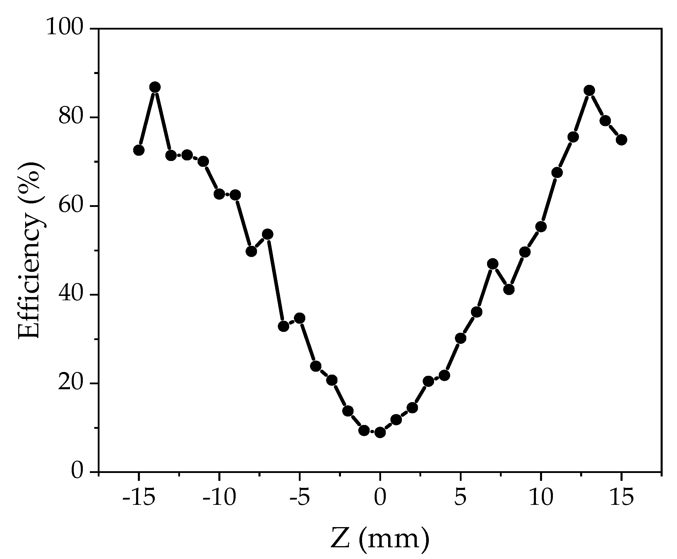
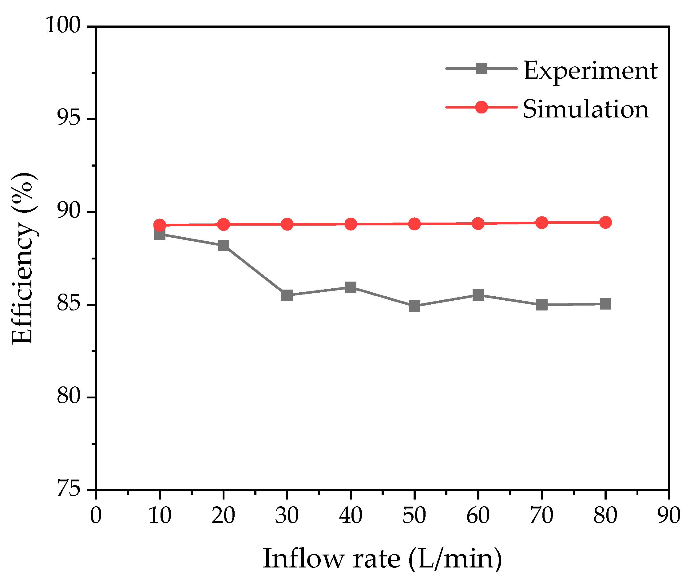
4.3. Microwave Efficiency Analysis

Based on the four-port horizontal gas inlet unit, the influence of inflow rate on microwave efficiency was further investigated. In the experiment, the feed power of each port is 996 W, 999.67 W, 999.3 W and 998.3 W, respectively, and the total feed power is 3993.27 W. The reflected power of each port shown as Figure 13, the microwave efficiency shown as Figure 14.
The experimental results show that with an increase in inflow rate, the microwave efficiency gradually decreases first. When the inflow rate 30 L/min to 80 L/min, the microwave efficiency is maintained at about 85%, the average microwave efficiency of the system is 86%. The simulation results show that the microwave efficiency stays at about 88% with an increase in inflow rate. The error rate between experimental and simulation results is 3.83%.

5. Conclusions

In this paper, a large-scale microwave plasma torch device based on four ports was designed. Based on the conductive properties of plasma, the plasma and coupling cavity can form quasi-coaxial structure. The coupling cavity and quartz tube are filled with focusing dielectric to form surface waves with high electric field intensity on the plasma surface, so as to improve the plasma size and uniformity. Based on electromagnetic field simulation results, the geometric structure of the plasma generator was improved and optimized. Four kinds of gas inlet units were designed, and simulation analysis and experimental verification were carried out. The experimental results show that the maximum height of the plasma torch is 545 mm (for inflow rate 20 L/min), the diameter of the plasma torch reaches to 63 mm, the working range of the device is 10 to 95 L/min, and the average microwave efficiency of the device is 86%. In the future, the large-scale MPT can be more attractive in industrial application, and this device can be applied in solid waste treatment, commercial scale hydrogen production and other fields.

Supplementary Materials

The following supporting information can be downloaded at: https://www.mdpi.com/article/10.3390/pr11092589/s1.

Author Contributions

Y.H. developed the model, finished the experiment, analyzed the data, and wrote the initial draft of the manuscript; W.Z. and J.H. conceived and designed the experiment; H.Z. and Y.Y. reviewed and contributed to the final manuscript. All authors have read and agreed to the published version of the manuscript.

Funding

This work was supported by the National Natural Science Foundation of China under Grant Nos. 61971295 and 62001130, Nature Science Foundation of Sichuan Province 2022NSFSC0562, the Youth Science and Technology Talents Growth Project from Guizhou Provincial Department of Education Grant No. QJHKYZ [2020]087, the Guizhou Science and Technology Plan from Guizhou Provincial Department of Science and Technology Grant No. QKHJC-ZK [2021]297.

Data Availability Statement

All data and models generated or used during the study appear in the submitted article.

Conflicts of Interest

The authors declare no conflict of interest.

References

  1. Al-Shamma’a, A.I.; Wylie, S.R.; Lucas, J.; Pau, C.F. Design and construction of a 2.45 GHz waveguide-based microwave plasma jet at atmospheric pressure for material processing. J. Phys. D Appl. Phys. 2001, 34, 2734–2741. [Google Scholar] [CrossRef]
  2. Wylie, S.R.; Al-Shamma’a, A.I.; Lucas, J. Microwave plasma system for material processing. IEEE Trans. Plasma Sci. 2005, 33, 340–341. [Google Scholar] [CrossRef]
  3. Fleisch, T.; Kabouzi, Y.; Moisan, M.; Pollak, J.; Castaños-Martínez, E.; Nowakowska, H.; Zakrzewski, Z. Designing an efficient microwaveplasma source, independent of operating conditions, at atmospheric pressure. Plasma Sources Sci. Technol. 2006, 16, 173–182. [Google Scholar] [CrossRef]
  4. Wang, Z.; Zhang, G.X.; Jia, Z.D. A large-volume stable atmospheric air microwave plasma based on inductive coupling window—Rectangular resonator. IEEE Trans. Plasma Sci. 2014, 42, 1669–1673. [Google Scholar] [CrossRef]
  5. Xiao, W.; Liao, Y.; Wang, F.; Zhang, Z.; Zhu, H.; Yang, Y.; Huang, K. Determining Electron Density of Atmospheric Microwave Air Plasma Torch by Microwave Power Measurement. IEEE Trans. Plasma Sci. 2022, 50, 1781–1789. [Google Scholar] [CrossRef]
  6. Baeva, M.; Andrasch, M.; Ehlbeck, J.; Weltmann, K.D.; Loffhagen, D. Study of the Spatiotemporal Evolution of Microwave Plasma in Argon. IEEE Trans. Plasma Sci. 2014, 42, 2774–2775. [Google Scholar] [CrossRef]
  7. Tatarova, E.; Dias, F.M.; Felizardo, E.; Henriques, J.; Pinheiro, M.J.; Ferreira, C.M.; Gordiets, B. Microwave air plasma source at atmospheric pressure: Experiment and theory. J. Appl. Phys. 2010, 108, 123305. [Google Scholar] [CrossRef]
  8. Heberlein, J.V.R. Generation of thermal and pseudo-thermal plasmas. Pure Appl. Chem. 1992, 64, 629–636. [Google Scholar] [CrossRef]
  9. Zhang, W.; Tao, J.; Huang, K.; Wu, L. Numerical Investigation of the Surface Wave Formation in a Microwave Plasma Torch. IEEE Trans. Plasma Sci. 2017, 45, 2929–2939. [Google Scholar] [CrossRef]
  10. Shahnazari, A.; Rafiee, M.; Rohani, A.; Nagar, B.B.; Ebrahiminik, M.A.; Aghkhani, M.H. Identification of effective factors to select energy recovery technologies from municipal solid waste using multi-criteria decision making (MCDM): A review of thermochemical technologies. Sustain. Energy Technol. Assess. 2020, 40, 100737. [Google Scholar] [CrossRef]
  11. Yayalık, İ.; Koyun, A.; Akgün, M. Gasification of municipal solid wastes in plasma arc medium. Plasma Chem. Plasma Process. 2020, 40, 1401–1416. [Google Scholar] [CrossRef]
  12. Sanders, N.A.; Pfender, E. Measurement of anode falls and anode heat transfer in atmospheric pressure high intensity arcs. J. Appl. Phys. 1984, 55, 714–722. [Google Scholar] [CrossRef]
  13. Jenista, J.; Heberlein, J.; Pfender, E. Model for Anode Heat Transfer from an Electric Arc. In Proceedings of the 4th International Thermal Plasma Processes Conference, Athens, Greece, 15–18 July 1996. [Google Scholar]
  14. Gabbar, H.A.; Darda, S.A.; Damideh, V.; Hassen, I.; Aboughaly, M.; Lisi, D. Comparative study of atmospheric pressure DC, RF, and microwave thermal plasma torches for waste to energy applications. Sustain. Energy Technol. Assess. 2021, 47, 101447. [Google Scholar] [CrossRef]
  15. Kim, J.H.; Hong, Y.C.; Kim, H.S.; Uhm, H.S. Simple microwave plasma source at atmospheric pressure. J. Korean Phys. Soc. 2003, 42, S876–S879. [Google Scholar]
  16. Kwak, H.S.; Uhm, H.S.; Hong, Y.C.; Choi, E.H. Disintegration of carbon dioxide molecules in a microwave plasma torch. Sci. Rep. 2015, 5, 18436. [Google Scholar] [CrossRef]
  17. Shin, D.H.; Hong, Y.C.; Lee, S.J.; Kim, Y.J.; Cho, C.H.; Ma, S.H.; Chun, S.M.; Lee, B.J.; Uhm, H.S. A pure steam microwave plasma torch: Gasification of powdered coal in the plasma. Surf. Coat. Technol. 2013, 228, S520–S523. [Google Scholar] [CrossRef]
  18. Xiao, W.; Huang, K.; Zhang, W.; Lin, Y. Modeling of Argon Plasma Excited by Microwave at Atmospheric Pressure in Ridged Waveguide. IEEE Trans. Plasma Sci. 2016, 44, 1075–1082. [Google Scholar] [CrossRef]
  19. Chen, W.; Zhang, Y.; Wang, Y.; Zhong, Y.; Huang, K. A novel high-efficiency microwave plasma multi-ridges field compressed reactor. Phys. Plasmas 2023, 30, 023502. [Google Scholar] [CrossRef]
  20. D’Isa, F.A.; Carbone, E.; Hecimovic, A.; Fantz, U. Performance analysis of a 2.45 GHz microwave plasma torch for CO2 decomposition in gas swirl configuration. Plasma Sources Sci. Technol. 2020, 29, 105009. [Google Scholar] [CrossRef]
  21. Nowakowska, H.; Czylkowski, D.; Hrycak, B.; Jasiński, M. Characterization of a novel microwave plasma sheet source operated at atmospheric pressure. Plasma Sources Sci. Technol. 2018, 27, 085008. [Google Scholar] [CrossRef]
  22. Ouyang, Z.; Surla, V.; Cho, T.S.; Ruzic, D.N. Characterization of an atmospheric-pressure helium plasma generated by 2.45-GHz microwave power. IEEE Trans. Plasma Sci. 2012, 40, 3476–3481. [Google Scholar] [CrossRef]
  23. Leins, M.; Kopecki, J.; Gaiser, S.; Schulz, A.; Walker, M.; Schumacher, U.; Stroth, U.; Hirth, T. Microwave plasmas at atmospheric pressure. Contrib. Plasma Phys. 2014, 54, 14–26. [Google Scholar] [CrossRef]
  24. Kabouzi, Y.; Moisan, M.; Rostaing, J.; Trassy, C.; Guerin, D.; Kéroack, D.; Zakrzewski, Z. Abatement of perfluorinated compounds using microwave plasmas at atmospheric pressure. J. Appl. Phys. 2003, 93, 9483–9496. [Google Scholar] [CrossRef]
  25. Hrycak, B.; Czylkowski, D.; Miotk, R.; Dors, M.; Jasinski, M.; Mizeraczyk, J. Application of atmospheric pressure microwave plasma source for hydrogen production from ethanol. Int. J. Hydrogen Energy 2014, 39, 14184–14190. [Google Scholar] [CrossRef]
  26. Darafsheh, A. Optical Super-Resolution and Periodical Focusing Effects by Dielectric Microspheres. Ph.D. Dissertation, University of North Carolina at Charlotte, Charlotte, NC, USA, 2013. [Google Scholar]
  27. Cuenca, J.A.; Mandal, S.; Thomas, E.L.H.; Williams, O.A. Microwave plasma modelling in clamshell chemical vapour deposition diamond reactors. Diam. Relat. Mater. 2022, 124, 108917. [Google Scholar] [CrossRef]
  28. Su, J.J.; Li, Y.F.; Li, X.L.; Yao, P.L.; Liu, Y.Q.; Ding, M.H.; Tang, W.Z. A novel microwave plasma reactor with a unique structure for chemical vapor deposition of diamond films. Diam. Relat. Mater. 2014, 42, 28–32. [Google Scholar] [CrossRef]
  29. Lieberman, M.A.; Lichtenberg, A.J. Principles of Plasma Discharges and Materials Processing, 2nd ed.; Wiley: Hoboken, NJ, USA, 2005; pp. 95–97. [Google Scholar]
  30. Shen, Q.; Huang, R.; Xu, Z.; Hua, W. Numerical 3D Modeling: Microwave Plasma Torch at Intermediate Pressure. Appl. Sci. 2020, 10, 5393. [Google Scholar] [CrossRef]
  31. Baeva, M.; Hempel, F.; Baierl, H.; Trautvetter, T.; Foest, R.; Loffhagen, D. Two- and three-dimensional simulation analysis of microwave excited plasma for deposition applications: Operation with argon at atmospheric pressure. J. Phys. D Appl. Phys. 2018, 51, 385202. [Google Scholar] [CrossRef]
  32. Lazarou, C.; Anastassiou, C.; Topala, I.; Chiper, A.S.; Mihaila, I.; Pohoata, V.; Georghiou, G.E. Numerical simulation of capillary helium and helium-oxygen atmospheric pressure plasma jets: Propagation dynamics and interaction with dielectric. Plasma Sources Sci. Technol. 2018, 27, 105007. [Google Scholar] [CrossRef]
  33. Lazarou, C.; Belmonte, T.; Chiper, A.S.; Georghiou, G.E. Numerical modelling of the effect of dry air traces in a helium parallel plate dielectric barrier discharge. Plasma Sources Sci. Technol. 2016, 25, 055023. [Google Scholar] [CrossRef]
  34. Ashida, S.; Lee, C.; Lieberman, M.A. Spatially averaged (global) model of time modulated high density argon plasmas. J. Vac. Sci. Technol. A Vac. Surf. Films 1995, 13, 2498–2507. [Google Scholar] [CrossRef]
  35. Baeva, M.; Andrasch, M.; Ehlbeck, J.; Loffhagen, D.; Weltmann, K.-D. Temporally and spatially resolved characterization of microwave induced argon plasmas: Experiment and modeling. J. Appl. Phys. 2014, 115, 143301. [Google Scholar] [CrossRef]
  36. Nakajima, J.; Sekiguchi, H. Synthesis of ammonia using microwave discharge at atmospheric pressure. Thin Solid Films 2018, 516, 4446–4451. [Google Scholar] [CrossRef]
  37. Zhong, N.; Chen, W.; Zhang, Y.; Wu, L.; Huang, K. A Novel High Energy Efficiency Dual-Channel Microwave Plasma Jet Using Strip Line. IEEE Trans. Plasma Sci. 2021, 49, 3086–3091. [Google Scholar] [CrossRef]
  38. Zhang, W.; Wu, L.; Tao, J.; Huang, K. Numerical Investigation of the Gas Flow Effects on Surface Wave Propagation and Discharge Properties in a Microwave Plasma Torch. IEEE Trans. Plasma Sci. 2019, 47, 271–277. [Google Scholar] [CrossRef]
Figure 1. Geometry of MPT device.
Processes 11 02589 g001
Figure 2. Geometry of the plasma generator.
Processes 11 02589 g002
Figure 3. Geometry of the gas inlet unit. (a) Two-hole horizontal; (b) two-hole inclined 30°; (c) four-hole horizontal; (d) four-hole inclined 30°.
Processes 11 02589 g003aProcesses 11 02589 g003b
Figure 4. The microwave efficiency at different the radius of the microwave cavity and the quartz tube.
Processes 11 02589 g004
Figure 5. The microwave efficiency at different position of the ports.
Processes 11 02589 g005
Figure 6. The streamline chart for the inflow rate 10 L/min. (a) Two-hole horizontal; (b) two-hole inclined 30°; (c) four-hole horizontal; (d) four-hole inclined 30°.
Processes 11 02589 g006
Figure 7. Electromagnetic loss power.
Processes 11 02589 g007
Figure 8. The simulation results. (a) The electron density distribution; (b) the electric field distribution.
Processes 11 02589 g008
Figure 9. Schematic drawing of the MPT experimental system.
Processes 11 02589 g009
Figure 10. Photograph of the MPT experimental system.
Processes 11 02589 g010
Figure 11. The height of plasma torches in different gas inlet modes.
Processes 11 02589 g011
Figure 12. The plasma torches under the four gas inlet units for inflow rate 20 L/min (a) Two-hole horizontal, (b) two-hole inclined 30°, (c) four-hole horizontal, (d) four-hole inclined 30°.
Processes 11 02589 g012
Figure 13. The reflected power of four ports for different inflow rates.
Processes 11 02589 g013
Figure 14. The microwave efficiency for different inflow rates.
Processes 11 02589 g014
Table 1. Reactions used in the model.
No.ReactionRate Coefficient Kj Δ ε j (eV)Ref.
1 e + A r e + A r ( 4 s ) 5 × 10 15 T e 0.74 exp ( 11.56 / T e ) 11.56[34]
2 e + A r e + A r ( 4 p ) 1.4 × 10 14 T e 0.71 exp ( 13.17 / T e ) 13.17[34]
3 e + A r ( 4 s ) e + A r ( 4 p ) 8.9 × 10 13 T e 0.51 exp ( 1.61 / T e ) 1.61[34]
4 e + A r ( 4 s ) e + A r 4.3 × 10 16 T e 0.74 −11.56[34]
5 e + A r ( 4 p ) e + A r 3.9 × 10 16 T e 0.71 −13.17[34]
6 e + A r ( 4 p ) e + A r ( 4 s ) 3 × 10 13 T e 0.51 −1.61[34]
7 e + A r 2 e + A r + 2.3 × 10 14 T e 0.68 exp ( 15.76 / T e ) 15.76[34]
8 2 e + A r + e + A r 8.75 × 10 39 T e 4.5 −15.76[35]
9 A r ( 4 p ) + A r ( 4 p ) e + A r + A r + 1.625 × 10 16 T 0.5 [35]
10 A r ( 4 p ) + A r A r + A r 3 × 10 21 [35]
Disclaimer/Publisher’s Note: The statements, opinions and data contained in all publications are solely those of the individual author(s) and contributor(s) and not of MDPI and/or the editor(s). MDPI and/or the editor(s) disclaim responsibility for any injury to people or property resulting from any ideas, methods, instructions or products referred to in the content.

